CN112858389B - Imaging dew point meter - Google Patents
Imaging dew point meterDownload PDFInfo
- Publication number
- CN112858389B CN112858389BCN202011620801.XACN202011620801ACN112858389BCN 112858389 BCN112858389 BCN 112858389BCN 202011620801 ACN202011620801 ACN 202011620801ACN 112858389 BCN112858389 BCN 112858389B
- Authority
- CN
- China
- Prior art keywords
- detection
- camera
- dew point
- imaging
- mirror
- Prior art date
- Legal status (The legal status is an assumption and is not a legal conclusion. Google has not performed a legal analysis and makes no representation as to the accuracy of the status listed.)
- Active
Links
Images


Classifications
- G—PHYSICS
- G01—MEASURING; TESTING
- G01N—INVESTIGATING OR ANALYSING MATERIALS BY DETERMINING THEIR CHEMICAL OR PHYSICAL PROPERTIES
- G01N25/00—Investigating or analyzing materials by the use of thermal means
- G01N25/56—Investigating or analyzing materials by the use of thermal means by investigating moisture content
- G01N25/66—Investigating or analyzing materials by the use of thermal means by investigating moisture content by investigating dew-point
- G—PHYSICS
- G01—MEASURING; TESTING
- G01N—INVESTIGATING OR ANALYSING MATERIALS BY DETERMINING THEIR CHEMICAL OR PHYSICAL PROPERTIES
- G01N21/00—Investigating or analysing materials by the use of optical means, i.e. using sub-millimetre waves, infrared, visible or ultraviolet light
- G01N21/01—Arrangements or apparatus for facilitating the optical investigation
- G01N21/15—Preventing contamination of the components of the optical system or obstruction of the light path
- G—PHYSICS
- G01—MEASURING; TESTING
- G01N—INVESTIGATING OR ANALYSING MATERIALS BY DETERMINING THEIR CHEMICAL OR PHYSICAL PROPERTIES
- G01N21/00—Investigating or analysing materials by the use of optical means, i.e. using sub-millimetre waves, infrared, visible or ultraviolet light
- G01N21/84—Systems specially adapted for particular applications
- G—PHYSICS
- G01—MEASURING; TESTING
- G01N—INVESTIGATING OR ANALYSING MATERIALS BY DETERMINING THEIR CHEMICAL OR PHYSICAL PROPERTIES
- G01N21/00—Investigating or analysing materials by the use of optical means, i.e. using sub-millimetre waves, infrared, visible or ultraviolet light
- G01N21/01—Arrangements or apparatus for facilitating the optical investigation
- G01N21/15—Preventing contamination of the components of the optical system or obstruction of the light path
- G01N2021/155—Monitoring cleanness of window, lens, or other parts
Landscapes
- Physics & Mathematics (AREA)
- Health & Medical Sciences (AREA)
- Life Sciences & Earth Sciences (AREA)
- Chemical & Material Sciences (AREA)
- Analytical Chemistry (AREA)
- Biochemistry (AREA)
- General Health & Medical Sciences (AREA)
- General Physics & Mathematics (AREA)
- Immunology (AREA)
- Pathology (AREA)
- Investigating Or Analyzing Materials Using Thermal Means (AREA)
Abstract
Description
Translated fromChinese技术领域technical field
本发明涉及结露测量技术领域,更具体地,涉及一种成像式露点仪。The present invention relates to the technical field of dew condensation measurement, in particular to an imaging dew point meter.
背景技术Background technique
现有的露点仪工作原理是:当被测气体进入结露室,并以一定的流速掠过镜面,镜面温度高于该气体的露点温度,干燥的镜面将光源的入射光近乎于全反射。露点仪进行测量时,首先根据光电检测器检测到的反射光的强度来控制制冷装置,使镜面温度下降,直至镜面结露或结霜,此时入射光在镜面上将会产生漫反射,反射光的强度则会相应改变,光电检测器感应到反射光信号的变化,锁定温度,此时的温度就是该气体的露点值。The working principle of the existing dew point meter is: when the gas to be measured enters the condensation chamber and passes over the mirror at a certain flow rate, the temperature of the mirror is higher than the dew point temperature of the gas, and the dry mirror almost totally reflects the incident light of the light source. When the dew point meter is used for measurement, the refrigeration device is first controlled according to the intensity of the reflected light detected by the photoelectric detector, so that the temperature of the mirror surface drops until the mirror surface condenses or frosts. The intensity of the light will change accordingly, and the photodetector senses the change of the reflected light signal and locks the temperature. The temperature at this time is the dew point value of the gas.
目前大部分露点仪采用的感光器件均采用单一的感光器件如光敏二极管、光敏电阻及光电管等对镜面反射光进行测量,该方法可靠性和抗干扰性较差,精度较低,再者,当镜面上有污物或划痕时,入射光在镜面会提前产生漫反射,导致光电检测器提前锁定温度,而此时的温度实际上并非该气体的露点值。At present, most of the photosensitive devices used in dew point meters use single photosensitive devices such as photodiodes, photoresistors and photoelectric tubes to measure the mirror reflected light. This method has poor reliability, anti-interference and low precision. Furthermore, When there is dirt or scratches on the mirror surface, the incident light will be diffusely reflected on the mirror surface in advance, causing the photodetector to lock the temperature in advance, and the temperature at this time is actually not the dew point value of the gas.
发明内容Contents of the invention
本发明旨在克服上述现有技术的至少一种缺陷(不足),提供一种成像式露点仪,用于解决露点仪可靠性和抗干扰性差的问题,使得露点的测量值更加准确。The present invention aims at overcoming at least one defect (deficiency) of the above-mentioned prior art, and provides an imaging dew point meter, which is used to solve the problem of poor reliability and anti-interference of the dew point meter, so that the measured value of the dew point is more accurate.
本发明采取的技术方案是,提供一种成像式露点仪,包括控制系统、结露系统、散热系统、光电检测系统,所述结露系统、散热系统、光电检测系统分别与所述控制系统连接,所述结露系统包括镜面,所述光电检测系统包括光电成像装置和检测盖体;所述检测盖体包括检测腔和设置于所述检测腔上方的检测上盖,所述光电成像装置设置于检测上盖内;所述光电成像装置包括光源和摄像机,所述摄像机设置有镜头,所述光源设置于检测上盖的一侧,所述摄像机设置于检测上盖的中间;其中,所述控制系统通过控制所述摄像机使所述摄像机以固定时间间隔连续拍摄镜面图像,并将所述摄像机拍摄的图像传输给所述控制系统,所述控制系统对所述摄像机拍摄到的图像进行分析,进而控制所述结露系统,得出露点。The technical solution adopted by the present invention is to provide an imaging dew point meter, including a control system, a dew condensation system, a heat dissipation system, and a photoelectric detection system, and the dew condensation system, heat dissipation system, and photoelectric detection system are respectively connected to the control system , the dew condensation system includes a mirror, the photoelectric detection system includes a photoelectric imaging device and a detection cover; the detection cover includes a detection cavity and a detection upper cover arranged above the detection cavity, and the photoelectric imaging device is set In the detection upper cover; the photoelectric imaging device includes a light source and a camera, the camera is provided with a lens, the light source is arranged on one side of the detection upper cover, and the camera is arranged in the middle of the detection upper cover; wherein, the The control system controls the camera so that the camera continuously captures mirror images at fixed time intervals, and transmits the images captured by the camera to the control system, and the control system analyzes the images captured by the camera, Then control the dew condensation system to obtain the dew point.
本方案中,所述控制系统根据绝对值差分法,将摄像机按时间顺序拍摄的第1张摄像图像中的所有像素的亮度与第2张及以后的各摄像图像中的所有像素的亮度进行顺序比较,比较同一像素中亮度差的绝对值,将每张图像与第1张图像亮度差绝对值分解为256灰度,制作每张图像与第1张图像的灰度直方图,亮度差为0的像素忽略,根据分析灰度直方图的结果,控制系统控制结露系统调整温度,检测出露点值。In this solution, the control system sequentially compares the brightness of all pixels in the first captured image captured by the camera in chronological order with the brightness of all pixels in the second and subsequent captured images according to the absolute value difference method Compare, compare the absolute value of the brightness difference in the same pixel, decompose the absolute value of the brightness difference between each image and the first image into 256 gray levels, and make a gray histogram of each image and the first image, the brightness difference is 0 According to the results of analyzing the gray histogram, the control system controls the condensation system to adjust the temperature and detect the dew point value.
与现有技术相比,通过分析镜面表面的图像,可以提高被测气体中露点的测量精度,并可以在短时间内对被测气体中的露点进行测量,再者,通过差分化处理,除去了镜面由于污垢或划痕而引起的测量误差,从而提高了结露系统的检测灵敏度,从而可以大幅度提高测量精度,同时,对于摄像机镜头上的污垢和划痕而引起的误差,也可以被避免,提高了露点仪的可靠性和抗干扰性。Compared with the existing technology, by analyzing the image of the mirror surface, the measurement accuracy of the dew point in the measured gas can be improved, and the dew point in the measured gas can be measured in a short time. It eliminates the measurement error caused by dirt or scratches on the mirror surface, thereby improving the detection sensitivity of the condensation system, which can greatly improve the measurement accuracy. At the same time, the error caused by dirt and scratches on the camera lens can also be avoided. , Improve the reliability and anti-interference of the dew point meter.
进一步的,所述摄像机外罩有透明罩,所述透明罩连接在检测上盖上。本方案中,通过在摄像机外设置透明罩,使相机与检测环境隔开,保护相机不受到检测气体及水雾等的伤害。Further, the camera is covered with a transparent cover, and the transparent cover is connected to the detection upper cover. In this solution, a transparent cover is set outside the camera to separate the camera from the detection environment and protect the camera from damage by detection gas and water mist.
进一步的,所述透明罩的上表面内侧与所述摄像机的镜头表面密封连接。本方案中,将透明罩上表面与摄像机镜头表面密封连接,防止透明罩与摄像机镜头表面之间的间隙产生水雾。Further, the inner side of the upper surface of the transparent cover is sealingly connected with the lens surface of the camera. In this solution, the upper surface of the transparent cover is sealed and connected to the surface of the camera lens to prevent water mist from being generated in the gap between the transparent cover and the surface of the camera lens.
进一步的,所述透明罩上表面外侧位于摄像机视野范围外的位置设有湿度传感器,用于检测透明罩上表面外侧湿度变化。Further, a humidity sensor is provided outside the upper surface of the transparent cover outside the field of view of the camera to detect changes in humidity outside the upper surface of the transparent cover.
进一步的,所述透明罩的一侧安装有驱动箱,所驱动箱内部安装有驱动件,所述驱动件连接有除雾杆,所述驱动件驱动所述除雾杆在透明罩上表面来回摆动,进行透明罩的除雾工作。Further, a driving box is installed on one side of the transparent cover, and a driving part is installed inside the driving box, and the driving part is connected with a demist rod, and the driving part drives the demist rod back and forth on the upper surface of the transparent cover. Swing to perform the defogging work of the transparent cover.
进一步的,所述除雾杆为L字型;其中,所述除雾杆的一端在所述驱动箱内与所述驱动件连接,另一端伸至所述透明罩上表面外侧。Further, the defogging rod is L-shaped; wherein, one end of the defogging rod is connected to the driving member in the driving box, and the other end extends outside the upper surface of the transparent cover.
进一步的,所述除雾杆非连接于所述驱动件的一端内侧设置有除雾垫,所述除雾杆与所述除雾垫胶接连接。Further, a defogging pad is provided inside the end of the demisting rod that is not connected to the driving member, and the demisting rod is glued to the defogging pad.
本方案中,当湿度传感器检测到透明罩上表面外侧湿度变化时,所述湿度传感器向控制系统发送信号,控制系统控制驱动件驱动除雾杆摆动,带动所述除雾垫擦拭透明罩上表面外侧,除去透明罩上表面外侧的雾气,保证摄像机所拍摄图像的质量。In this solution, when the humidity sensor detects changes in humidity outside the upper surface of the transparent cover, the humidity sensor sends a signal to the control system, and the control system controls the driving part to drive the defogging rod to swing, driving the defogging pad to wipe the upper surface of the transparent cover On the outside, the mist on the outside of the upper surface of the transparent cover is removed to ensure the quality of the image captured by the camera.
进一步的,所述摄像机和驱动箱上设置有散热片,使得摄像机和驱动件散发的热量及时散发出去。Further, the camera and the drive box are provided with cooling fins, so that the heat dissipated by the camera and the drive can be dissipated in time.
进一步的,所述结露系统还包括:测温计,用于检测温度;制冷片,其上表面为制冷面,下表面为散热面;导热结构,其下表面与所述制冷面连接,以将所述制冷面的冷量传递至所述导热结构的上表面,所述导热结构还连接与所述测温计;所述镜面,其下表面与所述导热结构上表面连接,以将所述导热结构上表面的冷量传递至所述镜面的上表面,使作业环境中的水蒸气结露于所述镜面的上表面;其中,所述测温计为铂电阻,且其外表面设有导热硅脂层或导热胶层;所述镜面为硅片,且其外表面设有铂层或金层或铑层。Further, the dew condensation system further includes: a thermometer for detecting temperature; a cooling plate whose upper surface is a cooling surface and whose lower surface is a heat dissipation surface; a heat conduction structure whose lower surface is connected to the cooling surface to Transfer the cold energy of the cooling surface to the upper surface of the heat conduction structure, and the heat conduction structure is also connected to the thermometer; the lower surface of the mirror surface is connected to the upper surface of the heat conduction structure, so that the The cold energy on the upper surface of the heat conduction structure is transferred to the upper surface of the mirror, so that the water vapor in the working environment is condensed on the upper surface of the mirror; wherein, the thermometer is a platinum resistance, and its outer surface is set There is a heat-conducting silicone grease layer or a heat-conducting adhesive layer; the mirror surface is a silicon wafer, and its outer surface is provided with a platinum layer, a gold layer, or a rhodium layer.
本方案中,所述测温计通过检测导热结构的温度,间接测量出镜面的温度,从而测量出水汽的温度。所述制冷片通过热电制冷原理,其制冷面形成冷量作用于导热结构,其散热面形成热量作用于连接该散热面的部件。所述导热结构用于将来自制冷片的冷量传递至所述镜面。所述镜面的上表面为结露的场所。所述镜面设置为硅片,其表面平整光亮且导热效率较高。In this solution, the thermometer indirectly measures the temperature of the mirror surface by detecting the temperature of the heat conducting structure, thereby measuring the temperature of the water vapor. The refrigerating sheet adopts the principle of thermoelectric refrigeration, the cooling surface forms cold energy to act on the heat conduction structure, and the heat dissipation surface forms heat to act on the components connected to the heat dissipation surface. The heat conduction structure is used to transfer the cold energy from the cooling sheet to the mirror surface. The upper surface of the mirror is a place for dew condensation. The mirror surface is set as a silicon wafer, the surface of which is flat and bright and has high heat conduction efficiency.
本方案中,所述制冷片的制冷面所产生的冷量通过所述导热结构传递到所述镜面的上表面,以使作业环境中的水蒸气结露到镜面的上表面,再通过测温计检测出导热结构的温度,从而间接检测出镜面的温度,即检测出气体的露点温度,从而获得气体中的湿度。In this solution, the cold generated by the cooling surface of the cooling sheet is transferred to the upper surface of the mirror through the heat conduction structure, so that the water vapor in the working environment condenses on the upper surface of the mirror, and then the temperature is measured The meter detects the temperature of the heat-conducting structure, thereby indirectly detecting the temperature of the mirror surface, that is, detecting the dew point temperature of the gas, thereby obtaining the humidity in the gas.
本方案中,在镜面的外表面设有铂层或金层或铑层,舍弃了常规的镜面为铜且铜的外表面设有金层的技术,从而使得本方案能够提高镜面的抗污能力,且使得所述镜面不易被划损,避免检测精度受到不利影响。In this solution, a platinum layer, a gold layer, or a rhodium layer is provided on the outer surface of the mirror surface, and the conventional technology that the mirror surface is copper and the copper outer surface is provided with a gold layer is abandoned, so that this solution can improve the anti-pollution ability of the mirror surface , and make the mirror surface not easy to be scratched, so as to prevent the detection accuracy from being adversely affected.
进一步的,所述控制系统包括控制转接板、电气针、远程控制主机;所述散热系统包括散热座,所述散热座设有腔体;其中,所述控制转接板位于所述腔体内并连接于所述远程控制主机;所述电气针插装于所述腔体内且电连接所述控制转接板,所述电气针与所述散热座绝缘连接;其中,所述电气针还电连接于光电检测系统、结露系统;所述制冷片设有的散热面连接于所述散热座。Further, the control system includes a control adapter board, electrical needles, and a remote control host; the heat dissipation system includes a heat sink, and the heat sink is provided with a cavity; wherein, the control adapter plate is located in the cavity and connected to the remote control host; the electrical needle is inserted into the cavity and electrically connected to the control adapter board, and the electrical needle is insulated and connected to the heat sink; wherein, the electrical needle is also electrically It is connected to the photoelectric detection system and the dew condensation system; the heat dissipation surface provided by the cooling plate is connected to the heat dissipation seat.
本方案中,所述散热座用于将所述制冷结构的散热面产生的热量散发出去。所述电气针与所述散热座绝缘连接,避免散热座对露点检测器的正常使用产生影响。所述腔体用于容纳所述控制转接板,且所述电气针插装于所述腔体内且电连接于所述控制转接板,以使得所述露点检测器的线路集中位于所述散热座的腔体内,避免线路露出露点检测器外界,从而影响检测效果并对线路造成损坏。In this solution, the heat dissipation seat is used to dissipate the heat generated by the heat dissipation surface of the refrigeration structure. The electrical needle is insulated and connected to the heat sink to prevent the heat sink from affecting the normal use of the dew point detector. The cavity is used to accommodate the control adapter board, and the electrical needle is inserted into the cavity and electrically connected to the control adapter board, so that the circuit of the dew point detector is concentrated on the In the cavity of the heat sink, prevent the circuit from being exposed to the outside of the dew point detector, thereby affecting the detection effect and causing damage to the circuit.
与现有技术相比,本发明的有益效果为:本发明设置了光电成像装置,通过拍摄、分析结露系统镜面表面的图像,得出露点值,可以提高被测气体中露点的测量精度,并可以在短时间内对被测气体中的露点进行测量,再者,通过差分化处理,除去了镜面由于污垢或划痕而引起的测量误差,从而提高了结露系统的检测灵敏度,从而可以大幅度提高测量精度,同时,对于摄像机镜头上的污垢和划痕而引起的误差,也可以被避免,提高了露点仪的可靠性和抗干扰性,在摄像机外设置透明罩和除雾装置,保护了摄像机的同时,也保证了摄像机所拍摄图像的质量,进而确保了露点的测量精度。Compared with the prior art, the beneficial effects of the present invention are as follows: the present invention is provided with a photoelectric imaging device, and the dew point value can be obtained by taking and analyzing the image of the mirror surface of the dew condensation system, which can improve the measurement accuracy of the dew point in the measured gas, And it can measure the dew point in the measured gas in a short time. Moreover, through differential treatment, the measurement error caused by dirt or scratches on the mirror surface is removed, thereby improving the detection sensitivity of the dew condensation system, which can greatly The range improves the measurement accuracy, and at the same time, the errors caused by dirt and scratches on the camera lens can also be avoided, which improves the reliability and anti-interference performance of the dew point meter. A transparent cover and defogging device are installed outside the camera to protect While improving the camera, it also ensures the quality of the image captured by the camera, thereby ensuring the measurement accuracy of the dew point.
附图说明Description of drawings
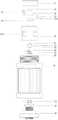
图1为本发明的爆炸图。Figure 1 is an exploded view of the present invention.
图2为本发明的剖面图。Fig. 2 is a sectional view of the present invention.
图3为本发明A部仰视图。Fig. 3 is a bottom view of part A of the present invention.
图4为本发明结露系统爆炸图。Fig. 4 is an exploded view of the dew condensation system of the present invention.
图5为本发明A部放大图。Fig. 5 is an enlarged view of part A of the present invention.
附图标记:检测上盖11、检测腔12、光源13、摄像机14、气孔121、透明罩21、驱动箱22、除雾杆23、除雾垫231、镜面31、密封圈32、导热结构33、测温计34、制冷片35、散热座41、航空接头42、散热尾盖43、腔体411、电气针51、控制转接板52。Reference signs: detection
具体实施方式detailed description
本发明附图仅用于示例性说明,不能理解为对本发明的限制。为了更好说明以下实施例,附图某些部件会有省略、放大或缩小,并不代表实际产品的尺寸;对于本领域技术人员来说,附图中某些公知结构及其说明可能省略是可以理解的。The accompanying drawings of the present invention are only for illustrative purposes, and should not be construed as limiting the present invention. In order to better illustrate the following embodiments, some components in the drawings will be omitted, enlarged or reduced, and do not represent the size of the actual product; for those skilled in the art, some known structures and their descriptions in the drawings may be omitted. understandable.
实施例Example
如图1所示,本实施例提供一种成像式露点仪,包括控制系统、结露系统、散热系统、光电检测系统,所述结露系统、散热系统、光电检测系统分别与所述控制系统连接。As shown in Figure 1, this embodiment provides an imaging dew point meter, including a control system, a dew condensation system, a heat dissipation system, and a photoelectric detection system, and the dew condensation system, heat dissipation system, and photoelectric detection system are respectively connected with the control system connect.
具体地,所述结露系统包括镜面31,所述光电检测系统包括光电成像装置和检测盖体,所述检测盖体包括检测腔12和设置于所述检测腔12上方的检测上盖11,所述光电成像装置设置于检测上盖11内,所述光电成像装置包括光源13和摄像机14,所述摄像机14设有镜头,所述光源13设置于检测上盖11的一侧,所述摄像机14设置于检测上盖11的中间,其中,所述控制系统通过控制所述摄像机14使所述摄像机14以固定时间间隔连续拍摄镜面31图像,并将所述摄像机14拍摄的图像传输给所述控制系统,控制系统接收到图像后根据绝对值差分法,将摄像机14按时间顺序拍摄的第1张摄像图像中的所有像素的亮度与第2张及以后的各摄像图像中的所有像素的亮度进行顺序比较,比较同一像素中亮度差的绝对值,将每张图像与第1张图像亮度差绝对值分解为256灰度,制作每张图像与第1张图像的灰度直方图,亮度差为0的像素忽略,根据分析灰度直方图的结果,控制系统控制结露系统调整温度,检测出露点值。Specifically, the dew condensation system includes a
在本实施例中,所述光源13采用LED发射光源,摄像机14拍摄镜面31照片的时间间隔为1/20秒。In this embodiment, the
如图2、图5所示,所述摄像机14外罩有透明罩21,所述透明罩21连接在检测上盖11上。As shown in FIG. 2 and FIG. 5 , the
为避免摄像机14受到被测气体及水雾的损坏,所述透明罩21的上表面内侧与所述摄像机14的镜头表面密封连接。In order to prevent the
进一步地,所述透明罩21上表面外侧位于摄像机14视野范围外的位置设有湿度传感器,用于检测透明罩21上表面外侧湿度变化。Further, a humidity sensor is provided outside the upper surface of the
如图3所示,所述透明罩21的一侧安装有驱动箱22,所驱动箱22内部安装有驱动件,所述驱动件连接有除雾杆23,所述驱动件驱动所述除雾杆23在透明罩21上表面来回摆动,进行透明罩21的除雾工作。As shown in Figure 3, a
具体地,所述除雾杆23为L字型;其中,所述除雾杆23的一端在所述驱动箱22内与所述驱动件连接,另一端伸至所述透明罩21上表面外侧。Specifically, the
进一步地,所述除雾杆23非连接于所述驱动件的一端内侧设置有除雾垫231,所述除雾杆23与所述除雾垫231胶接连接。Further, a
当湿度传感器检测到透明罩21上表面外侧湿度变化时,所述湿度传感器向控制系统发送信号,控制系统控制驱动件驱动除雾杆23摆动,带动所述除雾垫231擦拭透明罩21上表面外侧,除去透明罩21上表面外侧的雾气,保证了摄像机所拍摄图像的质量。When the humidity sensor detects that the humidity outside the upper surface of the
进一步地,所述摄像机14和驱动箱22上设置有散热片。Further, heat sinks are arranged on the
如图4所示,所述结露系统包括镜面31、密封圈32、导热结构33、测温计34、制冷片35。所述结露系统安装于所述散热系统上。所述结露系统的具体工作过程为:制冷片35通过热电制冷原理产生冷量,制冷片35产生的冷量通过所述导热结构33传递到镜面31的上表面,以使作业环境中的水蒸气结露到镜面31的上表面,形成冷凝物。所述结露系统再通过测温计34检测出导热结构33的温度,从而间接检测出镜面31的温度,由此可间接获得气体的湿度。As shown in FIG. 4 , the dew condensation system includes a
具体地,制冷片35具有制冷面和散热面,制冷片35的上表面为制冷面,其下表面为散热面。详细地,制冷片35可以为具有三层结构,但不仅限于三层结构。Specifically, the cooling
在本实施例中,制冷片35采用具有三层结构的制冷片,制冷片35最上层的结构的横截面积小于其它层的结构的横截面积。In this embodiment, the cooling
具体地,导热结构33用于传递来自于制冷片35的制冷面的冷量。详细地,导热结构33具有上表面和下表面,导热结构33的下表面与所述制冷面连接,以将所述制冷面的冷量传递至所述导热结构33的上表面。详细地,为了减小导热结构33的体积,导热结构33大体呈长方体状。详细地,为了减小所述结露系统的体积,对导热结构105作进一步的改进,导热结构33由侧面、上表面、下表面向内部凹陷以去除部分结构形成开放区域,所述测温计34嵌入所述开放区域中。详细地,所述开放区域大体呈长方体状。详细地,导热结构33可以由导热金属制成,优选为铜。Specifically, the
在本实施例中,所述为了进一步容纳所述测温计34,导热结构33作进一步改进,所述导热结构33由其外壁向内部凹陷形成凹槽,测温计34嵌入于凹槽内并与凹槽匹配。In this embodiment, in order to further accommodate the
具体地,镜面31为所述结露系统的结露场所。镜面31的下表面与所述导热结构33上表面连接,以将所述导热结构33上表面的冷量传递至所述镜面31的上表面,使作业环境中的水蒸气结露于所述镜面31的上表面形成冷凝物。详细地,为了提高导热效率,镜面31为硅片,所述硅片的截面大体上呈正方形状。详细地,为了提高镜面31的抗污能力,且使得所述镜面31不易被划损,在镜面31的外表面上设有铂层或金层或铑层,进一步地,所述铂层或金层或铑层设置于镜面31的上表面,进一步地,所述镜面31上设置有疏水材料层。Specifically, the
具体地,所述测温计34用于测温。详细地,测温计34大体呈长方体状,且测温计34与所述开放区域匹配。详细地,所述测温计34为铂电阻,为了进一步增大热量传导面积,所述铂电阻的外表面设有导热硅脂层或导热胶层,以使测温计34和导热结构33无间隙贴紧。Specifically, the
具体地,为了避免水汽通过结露系统渗入到露点传感器内部,本申请实施例采用了密封圈32进行密封。所述密封圈32具有连通上下表面的容纳腔,详细地,密封圈32大体为梯形台状,所述梯形台侧面沿导热结构33围绕形成一个框架体,并包裹住镜面31的周边。详细地,导热结构33、镜面31、测温计34均围蔽于密封圈32内,即导热结构33、镜面31、测温计34均位于所述容纳腔内。详细地,密封圈32的上表面与其下表面之间具有一定的距离,密封圈32的下端部围蔽于制冷片35的上端部。详细地,密封圈32的下端部包裹于制冷片35最上层结构的外围。详细地,为了将结露于镜面31上表面的水汽位于镜面31的上表面所在区域内,密封圈32的上表面与所述镜面31的上表面具有一定距离,且所述密封圈104的上表面高于所述镜面31的上表面。详细地,为了进一步提高所述结露系统的气密性,所述密封圈32与镜面31紧密连接,密封圈32可以为橡胶密封圈。Specifically, in order to prevent water vapor from infiltrating into the dew point sensor through the dew condensation system, the embodiment of the present application adopts a sealing
具体地,所述检测盖体安装于所述散热系统上后,所述结露系统位于所述检测腔12内。详细地,为了方便将光电成像装置、透明罩21、除雾杆23、驱动箱22安装于检测上盖11上端部,所述检测上盖11可拆卸地与检测腔12连接。具体地,所述结露系统位于所述检测腔12内。所述检测腔12侧壁上设有气孔121。Specifically, after the detection cover is installed on the heat dissipation system, the dew condensation system is located in the
其中,所述控制系统包括电气针51、控制转接板52、航空接头42、远程控制主机。Wherein, the control system includes an
具体地,电气针51用于电传导。详细地,电气针51由导电金属构成,且其设有若干根。电气针51的大小可以设置相同,也可以设置不相同。具体地,航空接头42还连接于远程控制主机,以便于远程控制主机与所述控制转接板52进行信息交互。所述控制转接板52,可通过远程控制主机设有的屏幕对当前检测状态和对应的参数进行观察,并通过远程控制主机对检测参数进行设置。详细地,电气针51可以通过焊接的方式与控制转接板52进行连接。另外,电气针51还可通过电缆电连接于光电检测系统、结露系统。Specifically,
其中,所述散热系统包括散热座41、散热尾盖43。Wherein, the heat dissipation system includes a
具体地,散热座41大体呈圆柱状。散热座41的上表面与所述结露系统的制冷结构107的散热面连接,以便将所述散热面所产生的热量通过散热座41散发出去。具体地,为了便于散热,散热座41可以由金属材料构成。详细地,散热座41下端部设有腔体411。Specifically, the
具体地,所述散热尾盖43上由下往上依次安装有航空接头42、控制转接板52,且航空接头42与控制转接板52连接。详细地,散热尾盖43安装于散热座41的下端部,散热尾盖43可以通过螺纹的方式连接于散热座41。Specifically, an
当散热尾盖43与散热座41完成安装,航空接头42、控制转接板52均位于所述腔体411内。详细地,所述航空接头42还可连接于电气针51。详细地,电气针51插装于所述腔体411内且电连接所述控制转接板52,所述电气针51与所述散热座41绝缘连接。电气针51可以由散热座41上端向下插装至所述腔体411。When the heat
其中,为了防止水蒸气和空气进入对露点检测器内部电路和元器件造成损坏、避免有毒气体通过腔体411泄露到外界、避免电气针51和散热座41导电、避免电气针51和控制转接板52之间连接产生错位,本申请实施例在腔体411内填充有密封剂。所述密封剂可以为胶水,详细地,灌胶于所述腔体411内,胶水密封所述腔体411。Among them, in order to prevent water vapor and air from entering to cause damage to the internal circuit and components of the dew point detector, to avoid the leakage of toxic gas to the outside through the
在本实施例中,为避免电气针51和散热座41导电,可以在所述腔体411内壁设置绝缘垫,所述绝缘垫可以为橡胶垫。In this embodiment, in order to avoid electrical conduction between the
在本实施例中,可以通过玻璃烧结工艺固定电气针51和控制转接板52。In this embodiment, the
在本实施例中,可以通过玻璃烧结工艺实现电气针51和散热座41之间密封耐气体压力。In this embodiment, the sealing and resistance to gas pressure between the
所述露点仪的具体工作过程为:光电成像装置中的摄像机14在露点仪开始工作前,拍下第一张图像,并以1/20秒的时间间隔连续地拍摄镜面31上的图像,每拍摄一张图像立即传至控制系统进行分析,作业环境中的水蒸气通过检测腔12时掠过镜面31的上表面。当镜面31的上表面的温度高于该气体的露点温度时,镜面31的上表面呈干燥状态。此时,在控制系统的控制下,光电成像装置通过转接控制板52和航空接头42发射信号至远程控制主机,并接收来自远程控制主机的反馈信号,所述反馈信号再经控制回路比较、放大后,使驱动制冷片35进行制冷。当镜面31的上表面的温度降至气体的露点温度以下时,镜面31的上表面开始结露,形成冷凝物,这时光电成像装置继续通过转接控制板52和航空接头42发射信号至远程控制主机,并接收来自远程控制主机的反馈信号,根据反馈信号的变化,再将所述反馈信号经控制回路比较、放大后调节制冷片35激励电流,改变制冷片35的制冷功率,使镜面31的上表面的温度与气体的露点温度一致。此时,通过测温计34,可以检测出镜面31的温度,从而获得气体中的露点或霜点。The specific work process of the dew point meter is: the
显然,本发明的上述实施例仅仅是为清楚地说明本发明技术方案所作的举例,而并非是对本发明的具体实施方式的限定。凡在本发明权利要求书的精神和原则之内所作的任何修改、等同替换和改进等,均应包含在本发明权利要求的保护范围之内。Apparently, the above-mentioned embodiments of the present invention are only examples for clearly illustrating the technical solution of the present invention, rather than limiting the specific implementation manner of the present invention. Any modification, equivalent replacement and improvement made within the spirit and principle of the claims of the present invention shall be included in the protection scope of the claims of the present invention.
Claims (9)
Priority Applications (1)
| Application Number | Priority Date | Filing Date | Title |
|---|---|---|---|
| CN202011620801.XACN112858389B (en) | 2020-12-31 | 2020-12-31 | Imaging dew point meter |
Applications Claiming Priority (1)
| Application Number | Priority Date | Filing Date | Title |
|---|---|---|---|
| CN202011620801.XACN112858389B (en) | 2020-12-31 | 2020-12-31 | Imaging dew point meter |
Publications (2)
| Publication Number | Publication Date |
|---|---|
| CN112858389A CN112858389A (en) | 2021-05-28 |
| CN112858389Btrue CN112858389B (en) | 2022-12-23 |
Family
ID=75999066
Family Applications (1)
| Application Number | Title | Priority Date | Filing Date |
|---|---|---|---|
| CN202011620801.XAActiveCN112858389B (en) | 2020-12-31 | 2020-12-31 | Imaging dew point meter |
Country Status (1)
| Country | Link |
|---|---|
| CN (1) | CN112858389B (en) |
Family Cites Families (3)
| Publication number | Priority date | Publication date | Assignee | Title |
|---|---|---|---|---|
| EP1417477A1 (en)* | 2001-08-03 | 2004-05-12 | General Eastern Instruments, Inc. | An image apparatus for gas analysis |
| CN204707185U (en)* | 2015-06-29 | 2015-10-14 | 杭州海康威视数字技术股份有限公司 | The anti-smog device of video camera and video camera |
| CN210690460U (en)* | 2019-10-09 | 2020-06-05 | 广州西森自动化控制设备有限公司 | Dew point instrument |
- 2020
- 2020-12-31CNCN202011620801.XApatent/CN112858389B/enactiveActive
Also Published As
| Publication number | Publication date |
|---|---|
| CN112858389A (en) | 2021-05-28 |
Similar Documents
| Publication | Publication Date | Title |
|---|---|---|
| JP4584347B2 (en) | Test apparatus and method for detecting poor contact of electrically conductive connection | |
| CN1547666A (en) | An Apparatus and Method for Providing Thermal Infrared Imaging Snapshot Actions in Automated Process Control Workpiece Inspection Applications | |
| CN112268930B (en) | Dew point sensor | |
| CN102608448A (en) | Detection machine station with mask | |
| CN1306582C (en) | Ball-grating array semiconductor device quality detecting system based on dual-eye machine vision | |
| WO2023092779A1 (en) | Photoelectric chilled mirror type dew point sensor | |
| CN112858389B (en) | Imaging dew point meter | |
| US7795589B2 (en) | Infrared sensor and method of calibrating the same | |
| CN117309937A (en) | Dew point temperature detection method and device integrating image recognition and reflection detection | |
| CN106885979A (en) | The evaluating apparatus and evaluation method of semiconductor device | |
| US20250261342A1 (en) | Moving Vehicle-Mounted Gimbal Platform Having a Heat Dissipating Columnar Housing | |
| KR20130035061A (en) | Solder Ball Inspection System | |
| CN112858387B (en) | A dew point detection device capable of filtering gas | |
| WO2022141143A1 (en) | Dew point instrument having cleaning device | |
| CN112394086B (en) | A dew condensation system and its dew point meter | |
| JP6888518B2 (en) | Leak measurement method and manufacturing method of light emitting device | |
| CN104580843B (en) | The Si CCD cameras and method of quick obtaining silicon chip luminescence generated by light image | |
| CN112816523B (en) | A dew point meter with cleaning device | |
| TW201839364A (en) | Motherboard analysis device and method | |
| CN216285029U (en) | A New Condensation System and Dew Point Meter | |
| CN216484743U (en) | Take dew condensation system and dew point hygrometer of encapsulation platform | |
| CN207751475U (en) | A kind of wave measurement device based on infrared imaging | |
| JP2007108110A (en) | Substrate inspection method and substrate inspection apparatus | |
| CN112858388B (en) | A Chilled Mirror Dew Point Meter Probe | |
| CN111816621A (en) | Waterproof pressure sensor and packaging method |
Legal Events
| Date | Code | Title | Description |
|---|---|---|---|
| PB01 | Publication | ||
| PB01 | Publication | ||
| SE01 | Entry into force of request for substantive examination | ||
| SE01 | Entry into force of request for substantive examination | ||
| CB02 | Change of applicant information | ||
| CB02 | Change of applicant information | Address after:510336 building 3, No.17 Yunjun Road, Huangpu District, Guangzhou City, Guangdong Province Applicant after:Guangzhou Aosong Electronics Co.,Ltd. Address before:510336 building 3, No.17 Yunjun Road, Huangpu District, Guangzhou City, Guangdong Province Applicant before:AOSONG (GUANGZHOU) ELECTRONICS Co.,Ltd. | |
| GR01 | Patent grant | ||
| GR01 | Patent grant | ||
| PE01 | Entry into force of the registration of the contract for pledge of patent right | ||
| PE01 | Entry into force of the registration of the contract for pledge of patent right | Denomination of invention:An imaging dew point meter Granted publication date:20221223 Pledgee:Agricultural Bank of China Limited Guangzhou Development Zone Branch Pledgor:Guangzhou Aosong Electronics Co.,Ltd. Registration number:Y2024980049153 |