CN112857559B - Self-powered wireless vibration monitoring node based on single-piezoelectric device - Google Patents
Self-powered wireless vibration monitoring node based on single-piezoelectric deviceDownload PDFInfo
- Publication number
- CN112857559B CN112857559BCN202110032826.6ACN202110032826ACN112857559BCN 112857559 BCN112857559 BCN 112857559BCN 202110032826 ACN202110032826 ACN 202110032826ACN 112857559 BCN112857559 BCN 112857559B
- Authority
- CN
- China
- Prior art keywords
- module
- terminal
- vibration
- voltage
- input
- Prior art date
- Legal status (The legal status is an assumption and is not a legal conclusion. Google has not performed a legal analysis and makes no representation as to the accuracy of the status listed.)
- Active
Links
Images


Classifications
- G—PHYSICS
- G01—MEASURING; TESTING
- G01H—MEASUREMENT OF MECHANICAL VIBRATIONS OR ULTRASONIC, SONIC OR INFRASONIC WAVES
- G01H11/00—Measuring mechanical vibrations or ultrasonic, sonic or infrasonic waves by detecting changes in electric or magnetic properties
- G01H11/06—Measuring mechanical vibrations or ultrasonic, sonic or infrasonic waves by detecting changes in electric or magnetic properties by electric means
- G01H11/08—Measuring mechanical vibrations or ultrasonic, sonic or infrasonic waves by detecting changes in electric or magnetic properties by electric means using piezoelectric devices
Landscapes
- Physics & Mathematics (AREA)
- General Physics & Mathematics (AREA)
- Measurement Of Mechanical Vibrations Or Ultrasonic Waves (AREA)
Abstract
Translated fromChinese
Description
Translated fromChinese技术领域technical field
本发明涉及一种自供电无线振动监测节点,尤其是涉及一种基于单压电器件的自供电无线振动监测节点。The invention relates to a self-powered wireless vibration monitoring node, in particular to a self-powered wireless vibration monitoring node based on a single piezoelectric device.
背景技术Background technique
传统的振动监测系统通常基于正压电效应的压电加速度传感器来实现,在监测设备结构振动状态时,压电加速度传感器将振动加速度信号转换成电信号,然后由二次仪表进行采样处理获取振动信号。随着无线传感网络技术的发展,振动监测系统也逐步趋向无线化方向发展,无线振动监测系统应运而生。无线振动监测系统可以实现对被测设备结构振动状态的远程无线实时监测,获得了广泛的应用。The traditional vibration monitoring system is usually implemented based on the piezoelectric acceleration sensor with positive piezoelectric effect. When monitoring the vibration state of the equipment structure, the piezoelectric acceleration sensor converts the vibration acceleration signal into an electrical signal, and then the secondary instrument performs sampling processing to obtain the vibration Signal. With the development of wireless sensor network technology, the vibration monitoring system is gradually developing in the direction of wireless, and the wireless vibration monitoring system came into being. The wireless vibration monitoring system can realize remote wireless real-time monitoring of the structural vibration state of the equipment under test, and has been widely used.
一个无线振动监测系统通常由数目众多的监测节点通过无线组网构成。单个无线振动监测节点主要包括采集元件和监测电路,其中采集元件为压电加速度传感器,监测电路由微控制器和无线发射模块等有源器件构成。压电加速度传感器是一种无源器件,其工作过程不需要依靠外部供电,但是构成监测电路的微控制器和无线发射模块等有源器件,其工作过程需要依靠外部供电。在野外环境下,无线振动监测节点的电能供应主要依赖干电池。由于干电池容量有限,因而需要定期更换。然而,由于监测节点数目众多且部分可能预埋在被测设备结构内部,因此干电池更换成本高昂甚至无法更换。A wireless vibration monitoring system usually consists of a large number of monitoring nodes through wireless networking. A single wireless vibration monitoring node mainly includes an acquisition element and a monitoring circuit, where the acquisition element is a piezoelectric acceleration sensor, and the monitoring circuit is composed of active devices such as a microcontroller and a wireless transmission module. The piezoelectric acceleration sensor is a passive device, and its working process does not need to rely on external power supply, but active devices such as microcontrollers and wireless transmission modules that constitute the monitoring circuit, its working process needs to rely on external power supply. In the field environment, the power supply of wireless vibration monitoring nodes mainly depends on dry batteries. Due to the limited capacity of dry batteries, they need to be replaced periodically. However, due to the large number of monitoring nodes and some of them may be pre-buried inside the structure of the device under test, the cost of dry battery replacement is high or even impossible.
近年来,通过振动能量收集来为无线振动监测节点提供电能得到了广泛研究。申请号为CN202010802294.5的中国专利中公开了一种基于振动能采集器的自供电传感器(即无线振动监测节点),该自供电传感器用于监测振动速度,其振动能采集基于压电换能器实现,振动速度检测采用速度传感器实现,振动能采集器为速度传感器及其信号调理电路提供电能,实现自供电。该方案中,振动能采集器和速度传感器为两个独立的模块,导致方案整体体积较大,且成本较高。In recent years, powering wireless vibration monitoring nodes via vibration energy harvesting has been extensively studied. The Chinese patent with application number CN202010802294.5 discloses a self-powered sensor based on a vibration energy harvester (that is, a wireless vibration monitoring node). The self-powered sensor is used to monitor vibration speed, and its vibration energy collection is based on piezoelectric transducers The vibration speed detection is realized by the speed sensor, and the vibration energy harvester provides electric energy for the speed sensor and its signal conditioning circuit to realize self-power supply. In this solution, the vibration energy harvester and the speed sensor are two independent modules, resulting in a large overall size and high cost of the solution.
发明内容Contents of the invention
本发明所要解决的技术问题是提供一种体积较小,且成本较低的基于单压电器件的自供电无线振动监测节点。The technical problem to be solved by the present invention is to provide a self-powered wireless vibration monitoring node based on a single piezoelectric device with a smaller volume and lower cost.
本发明解决上述技术问题所采用的技术方案为:一种基于单压电器件的自供电无线振动监测节点,包括采集元件和监测电路,所述的采集元件仅采用一个常规悬臂梁式的压电器件实现,所述的监测电路包括振动测量模块、能量收集模块、微控制器模块和无线发射模块,所述的压电器件用于感受环境振动后生成交流电压输出至所述的振动测量模块和所述的能量收集模块中,所述的振动测量模块对输入其内的交流电压进行峰值跟踪并输出与峰值成正比的峰值分压信号分别给所述的能量收集模块和所述的微控制器模块,同时对输入其内的交流电压进行整形触发并输出同频率的方波信号给所述的微控制器模块;所述的能量收集模块对输入其内的交流电压进行同步开关电感整流处理并输出第一直流电压和第二直流电压给所述的微控制器模块,并同时进行电能储存以及为所述的振动测量模块、所述的微控制器模块和所述的无线发射模块提供工作电源电压;所述的微控制器模块基于输入其内的峰值分压信号、同频方波信号、第一直流电压和第二直流电压确定所述的压电器件感受到振动加速度的幅值和频率,并传递给所述的无线发射模块进行无线发射。The technical solution adopted by the present invention to solve the above technical problems is: a self-powered wireless vibration monitoring node based on a single piezoelectric device, including an acquisition element and a monitoring circuit. The acquisition element only uses a conventional cantilever beam piezoelectric Device implementation, the monitoring circuit includes a vibration measurement module, an energy collection module, a microcontroller module and a wireless transmission module, and the piezoelectric device is used to sense the environmental vibration and generate an AC voltage output to the vibration measurement module and In the energy collection module, the vibration measurement module performs peak tracking on the AC voltage input therein and outputs a peak divided voltage signal proportional to the peak value to the energy collection module and the microcontroller respectively. module, and at the same time carry out shaping trigger on the AC voltage input into it and output a square wave signal with the same frequency to the microcontroller module; the energy collection module performs synchronous switch inductance rectification processing on the AC voltage input into it and Outputting the first DC voltage and the second DC voltage to the microcontroller module, and simultaneously storing electric energy and providing working power for the vibration measurement module, the microcontroller module and the wireless transmission module Voltage; the microcontroller module determines the magnitude and frequency of the vibration acceleration felt by the piezoelectric device based on the peak voltage divider signal, the same frequency square wave signal, the first DC voltage and the second DC voltage input therein , and pass it to the wireless transmission module for wireless transmission.
所述的压电器件具有正极性输出端和负极性输出端,所述的能量收集模块具有第一输入端、第二输入端、第三输入端、第四输入端、第一输出端、第二输出端和电源输出端,所述的振动测量模块具有第一输入端、第二输入端、电源输入端、第一输出端和第二输出端,所述的微控制器模块具有第一输入端、第二输入端、第三输入端、第四输入端、电源输入端、第一控制端、第二控制端和输出端,所述的无线发射模块具有电源输入端、信号输入端和输出端,所述的压电器件的正极性输出端、所述的能量收集模块的第一输入端和所述的振动测量模块的第一输入端连接,所述的压电器件的负极性输出端和所述的能量收集模块的第二输入端连接,所述的能量收集模块的第一输出端和所述的微控制器模块的第三输入端连接,所述的能量收集模块的第二输出端和所述的微控制器模块的第四输入端连接,所述的能量收集模块的电源输出端、所述的振动测量模块的电源输入端、所述的微控制器模块的电源输入端和所述的无线发射模块的电源输入端连接,所述的振动测量模块的第一输出端、所述的能量收集模块的第三输入端和所述的微控制器模块的第二输入端连接,所述的振动测量模块的第二输出端和所述的微控制器模块的第一输入端连接,所述的微控制器模块的第一控制端和所述的振动测量模块的第二输入端连接,所述的微控制器模块的第二控制端和所述的能量收集模块的第四输入连接,所述的微控制器模块的输出端和所述的无线发射模块的信号输入端连接,所述的压电器件感受环境振动后产生交流电压,其正极性输出端和负极性输出端之间输出差分交流电压给所述的能量收集模块,其正极性输出端输出单端交流电压给所述的振动测量模块,所述的振动测量模块对输入其内的单端交流电压进行峰值跟踪生成峰值分压信号以及整形触发生成同频方波信号,将峰值分压信号记为Vpeak,同频方波信号记为Vfreq,所述的振动测量模块的第一输出端输出峰值分压信号Vpeak给所述的能量收集模块和所述的微控制器模块,所述的振动测量模块的第二输出端输出同频方波信号Vfreq给所述的微控制器模块,所述的能量收集模块对输入其内的差分交流电压进行同步开关电感整流处理并输出第一直流电压和第二直流电压给所述的微控制器模块,将第一直流电压记为Vdc1,第二直流电压记为Vdc2;所述的微控制器模块基于输入其内的峰值分压信号、第一直流电压和同频方波信号,确定压电器件感受到振动加速度的幅值和频率,并传递给所述的无线发射模块进行无线发射。The piezoelectric device has a positive output terminal and a negative output terminal, and the energy collection module has a first input terminal, a second input terminal, a third input terminal, a fourth input terminal, a first output terminal, a Two output terminals and a power supply output terminal, the vibration measurement module has a first input terminal, a second input terminal, a power input terminal, a first output terminal and a second output terminal, and the microcontroller module has a first input terminal end, the second input end, the third input end, the fourth input end, the power input end, the first control end, the second control end and the output end, the wireless transmission module has a power input end, a signal input end and an output end terminal, the positive output terminal of the piezoelectric device, the first input terminal of the energy collection module and the first input terminal of the vibration measurement module are connected, and the negative output terminal of the piezoelectric device It is connected with the second input terminal of the energy collection module, the first output terminal of the energy collection module is connected with the third input terminal of the microcontroller module, and the second output terminal of the energy collection module is Terminal is connected with the fourth input terminal of the microcontroller module, the power output terminal of the energy harvesting module, the power input terminal of the vibration measurement module, the power input terminal of the microcontroller module and The power supply input terminal of the wireless transmission module is connected, the first output terminal of the vibration measurement module, the third input terminal of the energy collection module are connected with the second input terminal of the microcontroller module, The second output terminal of the vibration measurement module is connected to the first input terminal of the microcontroller module, and the first control terminal of the microcontroller module is connected to the second input terminal of the vibration measurement module connection, the second control terminal of the microcontroller module is connected to the fourth input of the energy collection module, the output terminal of the microcontroller module is connected to the signal input terminal of the wireless transmission module, The piezoelectric device generates an AC voltage after sensing the vibration of the environment, outputs a differential AC voltage between its positive output end and negative output end to the energy harvesting module, and outputs a single-ended AC voltage to the energy harvesting module at its positive output end. The above vibration measurement module, the vibration measurement module performs peak tracking on the input single-ended AC voltage to generate a peak voltage division signal and shaping triggers to generate a square wave signal with the same frequency, and the peak voltage division signal is recorded as Vpeak , and the same The frequency square wave signal is denoted as Vfreq , the first output terminal of the vibration measurement module outputs the peak voltage divided signal Vpeak to the energy collection module and the microcontroller module, and the vibration measurement module The second output terminal outputs the same frequency square wave signal Vfreq to the microcontroller module, and the energy collection module performs synchronous switching inductance rectification on the differential AC voltage input therein and outputs the first DC voltage and the second DC voltage. The DC voltage is given to the microcontroller module, and the first DC voltage is recorded as Vdc1 , and the second DC voltage is recorded as Vdc2 ; the microcontroller module is based on the peak voltage divided signal input therein, the first DC The voltage and the same-frequency square wave signal determine the amplitude and frequency of the vibration acceleration felt by the piezoelectric device, and transmit it to the wireless transmitting module for wireless transmission.
所述的能量收集模块包括第一NPN三极管、第二NPN三极管、第一PNP三极管、第二PNP三极管、第一电感、第一电容、第二电容、第三电容、第一二极管、第二二极管、第三二极管、第四二极管、第一PMOS管、第一电阻、第二电阻、直流变换器、锂电池和线性稳压器;所述的第一电容为无极性电容,所述的第二电容和所述的第三电容均为电解电容,所述的直流变换器具有输入端、输出端、控制端和接地端,所述的线性稳压器具有输入端、输出端和接地端,所述的第一NPN三极管的基极、所述的第二NPN三极管的集电极、所述的第一PNP三极管的基极和所述的第二PNP三极管的集电极连接且其连接端为所述的能量收集模块的第一输入端,所述的第一NPN三极管的集电极和所述的第二PNP三极管的基极连接,所述的第一PNP三极管的集电极和所述的第二NPN三极管的基极连接,所述的第一NPN三极管的发射极、所述的第一PNP三极管的发射极和所述的第一电容的一端连接,所述的第二NPN三极管的发射极、所述的第二PNP三极管的发射极和所述的第一电感的一端连接,所述的第一电感的另一端、所述的第一二极管的正极和所述的第四二极管的负极连接,所述的第一电容的另一端、所述的第二二极管的正极和所述的第三二极管的负极连接且其连接端为所述的能量收集模块的第二输入端,所述的第一二极管的负极、所述的第二二极管的负极、所述的第二电容的正极和所述的第一PMOS管的源极连接其连接端为所述的能量收集模块的第一输出端,所述的第一PMOS管的栅极为所述的能量收集模块的第三输入端,所述的第一PMOS管的漏极、所述的第三电容的正极、所述的第一电阻的一端和所述的直流变换器的输入端连接且其连接端为所述的能量收集模块的第二输出端,所述的第一电阻的另一端、所述的第二电阻的一端和所述的直流变换器的控制端连接且其连接端为所述的能量收集模块的第四输入端,所述的直流变换器的输出端、所述的锂电池的正极和所述的线性稳压器的输入端连接,所述的线性稳压器的输出端为所述的能量收集模块的电源输出端,所述的第三二极管的正极、所述的第四二极管的正极、所述的第二电容的负极、所述的第三电容的负极、所述的第二电阻的另一端、所述的直流变换器的接地端、所述的锂电池的负极和所述的线性稳压器的接地端连接且其连接端为所述的能量收集模块的参考地。该能量收集模块形成一个同步开关电感整流电路,在实现自供电工作的同时,通过对其内第一PMOS管的开关控制,可以实时调整其内第二电容上的第一直流电压,使第一直流电压维持在最大功率点附近,实现压电振动能量的最大功率跟踪提取,增大了能量的供应,同时通过将第三电容作为临时电能储存,可以有效降低内部直流变换器的启动频率,减少了能量的损失,由此在不增加电路复杂度的前提下,进一步提高了能量收集效率。The energy collection module includes a first NPN transistor, a second NPN transistor, a first PNP transistor, a second PNP transistor, a first inductor, a first capacitor, a second capacitor, a third capacitor, a first diode, a second Two diodes, a third diode, a fourth diode, a first PMOS transistor, a first resistor, a second resistor, a DC converter, a lithium battery, and a linear voltage regulator; the first capacitor is infinite The second capacitor and the third capacitor are electrolytic capacitors, the DC converter has an input terminal, an output terminal, a control terminal and a ground terminal, and the linear voltage regulator has an input terminal , output terminal and ground terminal, the base of the first NPN transistor, the collector of the second NPN transistor, the base of the first PNP transistor and the collector of the second PNP transistor connected and its connection terminal is the first input terminal of the energy harvesting module, the collector of the first NPN transistor is connected to the base of the second PNP transistor, and the collector of the first PNP transistor The electrode is connected to the base of the second NPN transistor, the emitter of the first NPN transistor, the emitter of the first PNP transistor are connected to one end of the first capacitor, and the first The emitter of the two NPN transistors, the emitter of the second PNP transistor are connected to one end of the first inductance, the other end of the first inductance, the anode of the first diode and the first inductance The cathode of the fourth diode is connected, the other end of the first capacitor, the anode of the second diode is connected to the cathode of the third diode, and its connection terminal is the The second input terminal of the energy harvesting module, the negative pole of the first diode, the negative pole of the second diode, the positive pole of the second capacitor and the source of the first PMOS transistor Its connecting end is the first output end of the energy collection module, the gate of the first PMOS transistor is the third input end of the energy collection module, and the drain of the first PMOS transistor is , the anode of the third capacitor, one end of the first resistor are connected to the input end of the DC converter and the connection end is the second output end of the energy collection module, the first resistor The other end of a resistor, one end of the second resistor are connected to the control terminal of the DC converter, and the connection terminal is the fourth input terminal of the energy collection module, and the output of the DC converter terminal, the positive pole of the lithium battery is connected to the input terminal of the linear voltage regulator, the output terminal of the linear voltage regulator is the power output terminal of the energy harvesting module, and the third and second The positive pole of the pole tube, the positive pole of the fourth diode, the negative pole of the second capacitor, the negative pole of the third capacitor, the other end of the second resistor, the DC converter The ground terminal of the lithium battery, the negative pole of the lithium battery and the ground terminal of the linear voltage regulator are connected, and the connection terminal is the reference ground of the energy collection module. The energy harvesting module forms a synchronous switching inductance rectification circuit. While realizing self-powered operation, the first DC voltage on the second capacitor inside can be adjusted in real time by controlling the switch of the first PMOS transistor inside, so that the first The DC voltage is maintained near the maximum power point, which realizes the maximum power tracking extraction of piezoelectric vibration energy and increases the energy supply. At the same time, by storing the third capacitor as temporary electric energy, it can effectively reduce the start-up frequency of the internal DC converter and reduce The loss of energy is reduced, thereby further improving the energy harvesting efficiency without increasing the complexity of the circuit.
所述的振动测量模块包括第三电阻、第四电阻、第五电阻、第六电阻、第七电阻、第五二极管、第六二极管、第一运算放大器、第二运算放大器、比较器、第四电容、NMOS管,所述的第一运算放大器和所述的第二运算放大器分别具有同相输入端、反相输入端、输出端、电源端和接地端,所述的比较器具有同相输入端、反相输入端、输出端、电源端和接地端,所述的第三电阻的一端为所述的振动测量模块的第一输入端,所述的第三电阻的另一端、所述的第四电阻的一端、所述的第一运算放大器的同相输入端和所述的比较器的同相输入端连接,所述的第一运算放大器的反相输入端、所述的第五二极管的正极和所述的第七电阻的一端连接,所述的第一运算放大器的输出端、所述的第五二极管的负极和所述的第六二极管的正极连接,所述的第七电阻的另一端、所述的第二运算放大器的反相输入端和所述的第二运算放大器的输出端连接且其连接端为所述的振动测量模块的第一输出端,所述的NMOS管的栅极为所述的振动测量模块的第二输入端,所述的第六二极管的负极、所述的第二运算放大器的同相输入端、所述的第四电容的一端和所述的NMOS管的漏极连接,所述的第五电阻的一端、所述的第六电阻的一端和所述的比较器的反相输入端连接,所述的比较器的输出端为所述的振动测量模块的第二输出端,所述的第一运算放大器的电源端、所述的第二运算放大器的电源端、所述的比较器的电源端和所述的第五电阻的另一端连接且其连接端为所述的振动测量模块的电源输入端,所述的第四电阻的另一端、所述的第六电阻的另一端、所述的第四电容的另一端、所述的NMOS管的源极、所述的第一运算放大器的接地端、所述的第二运算放大器的接地端和所述的比较器的接地端连接且其连接端为所述的振动测量模块的参考地。该振动测量模块实现了对压电峰值电压的高精度实时跟踪,并可输出峰值分压信号给能量收集模块用于最大功率点跟踪,同时通过对压电电压的整形触发生成同频率的方波型号用于计算振动加速度的频率大小,该振动测量模块在保持简单电路结构的同时实现了多种必要的功能操作。The vibration measurement module includes a third resistor, a fourth resistor, a fifth resistor, a sixth resistor, a seventh resistor, a fifth diode, a sixth diode, a first operational amplifier, a second operational amplifier, a comparison device, a fourth capacitor, an NMOS transistor, the first operational amplifier and the second operational amplifier have a non-inverting input terminal, an inverting input terminal, an output terminal, a power supply terminal and a ground terminal respectively, and the comparator has Non-inverting input terminal, inverting input terminal, output terminal, power supply terminal and ground terminal, one end of the third resistor is the first input end of the vibration measurement module, the other end of the third resistor, the One end of the fourth resistor, the non-inverting input of the first operational amplifier and the non-inverting input of the comparator are connected, the inverting input of the first operational amplifier, the fifth and second The anode of the pole tube is connected to one end of the seventh resistor, the output terminal of the first operational amplifier, the cathode of the fifth diode is connected to the anode of the sixth diode, and the The other end of the seventh resistor, the inverting input end of the second operational amplifier and the output end of the second operational amplifier are connected and the connection end is the first output end of the vibration measurement module, The gate of the NMOS transistor is the second input terminal of the vibration measurement module, the negative pole of the sixth diode, the non-inverting input terminal of the second operational amplifier, and the One end is connected to the drain of the NMOS transistor, one end of the fifth resistor and one end of the sixth resistor are connected to the inverting input end of the comparator, and the output end of the comparator is the second output end of the vibration measurement module, the power end of the first operational amplifier, the power end of the second operational amplifier, the power end of the comparator and the fifth resistor The other end of the connection is connected to the power input end of the vibration measurement module, the other end of the fourth resistor, the other end of the sixth resistor, the other end of the fourth capacitor, The source of the NMOS transistor, the ground terminal of the first operational amplifier, the ground terminal of the second operational amplifier and the ground terminal of the comparator are connected, and the connection terminal is the vibration measurement The reference ground of the module. The vibration measurement module realizes the high-precision real-time tracking of the piezoelectric peak voltage, and can output the peak voltage division signal to the energy harvesting module for maximum power point tracking, and at the same time generate a square wave with the same frequency by shaping and triggering the piezoelectric voltage The model is used to calculate the frequency of vibration acceleration. The vibration measurement module realizes a variety of necessary functional operations while maintaining a simple circuit structure.
所述的微控制器模块中预存有所述的压电器件的幅频特性曲线以及计时周期T,所述的微控制器模块基于输入其内的峰值分压信号Vpeak、同频方波信号Vfreq和第一直流电压Vdc1确定所述的压电器件感受到振动加速度的幅值和频率的具体方法为:微控制器模块上电后即启动计时,同时开始对输入其内的同频方波信号Vfreq进行上升沿计数,并对输入其内的峰值分压信号Vpeak和第一直流电压Vdc1进行连续AD采样,当一个计时周期结束时停止计数与采样,并对得到的计数值和采样值进行处理,得到振动加速度的幅值和频率,然后再进入下一个计时周期重新开始计数与采样,周而复始;其中,得到振动加速度的幅值和频率的具体过程为:将一个计时周期内的同频方波信号的上升沿计数值记为N,振动加速度的频率记为f,则f=N/T;将AD采样频率记为Fs,则一个计时周期内可以得到M组采样数据,M=Fs*T,每组采样数据中分别包括一个峰值分压信号采样值和一个第一直流电压采样值,计算M个峰值分压信号采样值的平均值并记为Vpeak_avg,计算M个第一直流电压采样值的平均值并记为Vdc1_avg,基于Vpeak_avg和Vdc1_avg计算压电器件的等效开路电压并记为Vpoc,则Vpoc=k*(1-exp(-π/2Q))/2*Vpeak_avg+(1+exp(-π/2Q))/2*Vdc1_avg,式中π为圆周率,exp表示以自然常数e为底的指数函数,k为所述的振动测量模块中第三电阻和第四电阻构成的一对分压电阻的分压系数,Q为所述的压电器件以及所述的能量收集模块中第一电感和第二电容构成的LC谐振电路的品质因子,k和Q由所用的元器件的参数值唯一确定,最后,基于f和Vpoc在预存的幅频特性曲线上进行搜索查找,得到振动加速度的幅值大小。The amplitude-frequency characteristic curve and timing cycle T of the piezoelectric device are pre-stored in the microcontroller module, and the microcontroller module is based on the peak voltage divider signal Vpeak and the same-frequency square wave signal input therein. Vfreq and the first DC voltage Vdc1 determine that the amplitude and frequency of the vibration acceleration experienced by the piezoelectric device are as follows: the microcontroller module starts timing after power-on, and simultaneously starts to input the same frequency in it. The square wave signal Vfreq performs rising edge counting, and performs continuous AD sampling on the input peak voltage divider signal Vpeak and the first DC voltage Vdc1 , and stops counting and sampling when a timing period ends, and counts the obtained Value and sampled value are processed to obtain the amplitude and frequency of the vibration acceleration, and then enter the next timing cycle to restart counting and sampling, repeating itself; wherein, the specific process of obtaining the amplitude and frequency of the vibration acceleration is: a timing cycle The rising edge count value of the square wave signal with the same frequency is recorded as N, and the frequency of the vibration acceleration is recorded as f, then f=N/T; if the AD sampling frequency is recorded as Fs , then M groups of samples can be obtained in one timing cycle Data, M=Fs *T, each group of sampling data includes a sampled value of the peak voltage divided signal and a sampled value of the first DC voltage, and calculates the average value of the sampled values of the M peak voltage divided signal and records it as Vpeak_avg , Calculate the average value of the M first DC voltage sampling values and record it as Vdc1_avg , calculate the equivalent open circuit voltage of the piezoelectric device based on Vpeak_avg and Vdc1_avg and record it as Vpoc , then Vpoc =k*(1-exp( -π/2Q))/2*Vpeak_avg +(1+exp(-π/2Q))/2*Vdc1_avg , where π is the circumference ratio, exp means the exponential function based on the natural constant e, and k is the The voltage division coefficient of a pair of voltage dividing resistors formed by the third resistance and the fourth resistance in the vibration measurement module mentioned above, Q is the first inductor and the second capacitor formed by the piezoelectric device and the energy collection module The quality factor of the LC resonant circuit, k and Q, are uniquely determined by the parameter values of the components used. Finally, based on f and Vpoc , a search is performed on the pre-stored amplitude-frequency characteristic curve to obtain the amplitude of the vibration acceleration.
与现有技术相比,本发明的优点在于通过振动测量模块、能量收集模块、微控制器模块和无线发射模块构建监测电路,压电器件用于感受环境振动后生成交流电压输出至振动测量模块和能量收集模块中,振动测量模块对输入其内的交流电压进行峰值跟踪并输出与峰值成正比的峰值分压信号分别给能量收集模块和微控制器模块,同时对输入其内的交流电压进行整形触发并输出同频率的方波信号给微控制器模块;能量收集模块对输入其内的交流电压进行同步开关电感整流处理并输出第一直流电压和第二直流电压给微控制器模块,并同时进行电能储存以及为振动测量模块、微控制器模块和无线发射模块提供工作电源电压,微控制器模块基于输入其内的峰值分压信号、同频方波信号和第一直流电压确定压电器件感受到振动加速度的幅值和频率,并传递给无线发射模块进行无线发射,本发明中,仅需要设置一个常规的常规悬臂梁式的压电器件,监测电路基于压电器件的输出信号即可同时实现内部有源器件的自供电和振动加速度的幅值和频率的获取,不需要额外再设置加速度传感器来采集振动加速度,整体体积较小,且成本较低。Compared with the prior art, the present invention has the advantage of constructing a monitoring circuit through a vibration measurement module, an energy collection module, a microcontroller module and a wireless transmission module, and the piezoelectric device is used to sense the environmental vibration to generate an AC voltage output to the vibration measurement module And in the energy harvesting module, the vibration measurement module tracks the peak value of the AC voltage input into it and outputs a peak voltage divider signal proportional to the peak value to the energy harvesting module and the microcontroller module respectively, and at the same time conducts peak tracking on the AC voltage input into it Shaping triggers and outputs a square wave signal of the same frequency to the microcontroller module; the energy harvesting module performs synchronous switch inductance rectification on the input AC voltage and outputs the first DC voltage and the second DC voltage to the microcontroller module, and Simultaneously store electric energy and provide working power supply voltage for the vibration measurement module, microcontroller module and wireless transmission module. The microcontroller module determines the piezoelectric The device feels the amplitude and frequency of the vibration acceleration, and transmits it to the wireless transmitting module for wireless transmission. In the present invention, only a conventional conventional cantilever beam piezoelectric device needs to be set, and the monitoring circuit is based on the output signal of the piezoelectric device. The self-power supply of internal active devices and the acquisition of the amplitude and frequency of vibration acceleration can be realized at the same time, and no additional acceleration sensor is required to collect vibration acceleration. The overall volume is small and the cost is low.
附图说明Description of drawings
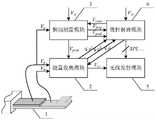
图1为本发明的基于单压电器件的自供电无线振动监测节点的结构框图;Fig. 1 is the structural block diagram of the self-powered wireless vibration monitoring node based on the single piezoelectric device of the present invention;
图2为本发明的基于单压电器件的自供电无线振动监测节点的能量收集模块的电路图;Fig. 2 is the circuit diagram of the energy harvesting module of the self-powered wireless vibration monitoring node based on the single piezoelectric device of the present invention;
图3为本发明的基于单压电器件的自供电无线振动监测节点的振动测量模块的电路图;Fig. 3 is the circuit diagram of the vibration measurement module of the self-powered wireless vibration monitoring node based on the single piezoelectric device of the present invention;
图4为本发明的基于单压电器件的自供电无线振动监测节点计算振动加速度的具体流程图。Fig. 4 is a specific flow chart of the calculation of vibration acceleration by the self-powered wireless vibration monitoring node based on the single piezoelectric device of the present invention.
具体实施方式Detailed ways
以下结合附图实施例对本发明作进一步详细描述。The present invention will be further described in detail below in conjunction with the accompanying drawings and embodiments.
实施例:如图1所示,一种基于单压电器件1的自供电无线振动监测节点,包括采集元件和监测电路,采集元件仅采用一个常规悬臂梁式的压电器件1实现,监测电路包括能量收集模块2、振动测量模块3、微控制器模块4和无线发射模块5,压电器件1用于感受环境振动后生成交流电压输出至振动测量模块3和能量收集模块2中,振动测量模块3对输入其内的交流电压进行峰值跟踪并输出与峰值成正比的峰值分压信号分别给能量收集模块2和微控制器模块4,同时对输入其内的交流电压进行整形触发并输出同频率的方波信号给微控制器模块4;能量收集模块2对输入其内的交流电压进行同步开关电感整流处理并输出第一直流电压和第二直流电压给微控制器模块4,并同时进行电能储存以及为振动测量模块3、微控制器模块4和无线发射模块5提供工作电源电压;微控制器模块4基于输入其内的峰值分压信号、同频方波信号和第一直流电压确定压电器件1感受到振动加速度的幅值和频率,并通过数据总线传递给无线发射模块5进行无线发射。Embodiment: As shown in Figure 1, a self-powered wireless vibration monitoring node based on a single
本实施例中,压电器件1具有正极性输出端和负极性输出端,能量收集模块2具有第一输入端、第二输入端、第三输入端、第四输入端、第一输出端、第二输出端和电源输出端,振动测量模块3具有第一输入端、第二输入端、电源输入端、第一输出端和第二输出端,微控制器模块4具有第一输入端、第二输入端、第三输入端、第四输入端、电源输入端、第一控制端、第二控制端和输出端,无线发射模块5具有电源输入端、信号输入端和输出端,压电器件1的正极性输出端、能量收集模块2的第一输入端和振动测量模块3的第一输入端连接,压电器件1的负极性输出端和能量收集模块2的第二输入端连接,能量收集模块2的第一输出端和微控制器模块4的第三输入端连接,能量收集模块2的第二输出端和微控制器模块4的第四输入端连接,能量收集模块2的电源输出端、振动测量模块3的电源输入端、微控制器模块4的电源输入端和无线发射模块5的电源输入端连接,振动测量模块3的第一输出端、能量收集模块2的第三输入端和微控制器模块4的第二输入端连接,振动测量模块3的第二输出端和微控制器模块4的第一输入端连接,微控制器模块4的第一控制端和振动测量模块3的第二输入端连接,微控制器模块4的第二控制端和能量收集模块2的第四输入连接,微控制器模块4的输出端和无线发射模块5的信号输入端连接,压电器件1感受环境振动后产生交流电压,其正极性输出端和负极性输出端之间输出差分交流电压给能量收集模块2,其正极性输出端输出单端交流电压给振动测量模块3,振动测量模块3对输入其内的单端交流电压进行峰值跟踪生成峰值分压信号以及整形触发生成同频方波信号,将峰值分压信号记为Vpeak,同频方波信号记为Vfreq,振动测量模块3的第一输出端输出峰值分压信号Vpeak给能量收集模块2和微控制器模块4,振动测量模块3的第二输出端输出同频方波信号Vfreq给微控制器模块4,能量收集模块2对输入其内的差分交流电压进行同步开关电感整流处理并输出第一直流电压和第二直流电压给微控制器模块4,将第一直流电压记为Vdc1,第二直流电压记为Vdc2;微控制器模块4基于输入其内的峰值分压信号、第一直流电压和同频方波信号,确定压电器件1感受到振动加速度的幅值和频率,并传递给无线发射模块5进行无线发射。In this embodiment, the
如图2所示,本实施例中,能量收集模块2包括第一NPN三极管NQ1、第二NPN三极管NQ2、第一PNP三极管PQ1、第二PNP三极管PQ2、第一电感L1、第一电容C1、第二电容C2、第三电容C3、第一二极管D1、第二二极管D2、第三二极管D3、第四二极管D4、第一PMOS管PM1、第一电阻R1、第二电阻R2、直流变换器U1、锂电池BAT1和线性稳压器U2;第一电容C1为无极性电容,第二电容C2和第三电容C3均为电解电容,直流变换器U1具有输入端、输出端、控制端和接地端,线性稳压器U2具有输入端、输出端和接地端,第一NPN三极管NQ1的基极、第二NPN三极管NQ2的集电极、第一PNP三极管PQ1的基极和第二PNP三极管PQ2的集电极连接且其连接端为能量收集模块2的第一输入端,第一NPN三极管NQ1的集电极和第二PNP三极管PQ2的基极连接,第一PNP三极管PQ1的集电极和第二NPN三极管NQ2的基极连接,第一NPN三极管NQ1的发射极、第一PNP三极管PQ1的发射极和第一电容C1的一端连接,第二NPN三极管NQ2的发射极、第二PNP三极管PQ2的发射极和第一电感L1的一端连接,第一电感L1的另一端、第一二极管D1的正极和第四二极管D4的负极连接,第一电容C1的另一端、第二二极管D2的正极和第三二极管D3的负极连接且其连接端为能量收集模块2的第二输入端,第一二极管D1的负极、第二二极管D2的负极、第二电容C2的正极和第一PMOS管PM1的源极连接其连接端为能量收集模块2的第一输出端,第一PMOS管PM1的栅极为能量收集模块2的第三输入端,第一PMOS管PM1的漏极、第三电容C3的正极、第一电阻R1的一端和直流变换器U1的输入端连接且其连接端为能量收集模块2的第二输出端,第一电阻R1的另一端、第二电阻R2的一端和直流变换器U1的控制端连接且其连接端为能量收集模块2的第四输入端,直流变换器U1的输出端、锂电池BAT1的正极和线性稳压器U2的输入端连接,线性稳压器U2的输出端为能量收集模块2的电源输出端,第三二极管D3的正极、第四二极管D4的正极、第二电容C2的负极、第三电容C3的负极、第二电阻R2的另一端、直流变换器U1的接地端、锂电池BAT1的负极和线性稳压器U2的接地端连接且其连接端为能量收集模块2的参考地。As shown in Figure 2, in this embodiment, the
如图3所示,本实施例中,振动测量模块3包括第三电阻R3、第四电阻R4、第五电阻R5、第六电阻R6、第七电阻R7、第五二极管D5、第六二极管D6、第一运算放大器U3、第二运算放大器U4、比较器U5、第四电容C4、NMOS管NM1,第一运算放大器U3和第二运算放大器U4分别具有同相输入端、反相输入端、输出端、电源端和接地端,比较器U5具有同相输入端、反相输入端、输出端、电源端和接地端,第三电阻R3的一端为振动测量模块3的第一输入端,第三电阻R3的另一端、第四电阻R4的一端、第一运算放大器U3的同相输入端和比较器U5的同相输入端连接,第一运算放大器U3的反相输入端、第五二极管D5的正极和第七电阻R7的一端连接,第一运算放大器U3的输出端、第五二极管D5的负极和第六二极管D6的正极连接,第七电阻R7的另一端、第二运算放大器U4的反相输入端和第二运算放大器U4的输出端连接且其连接端为振动测量模块3的第一输出端,NMOS管NM1的栅极为振动测量模块3的第二输入端,第六二极管D6的负极、第二运算放大器U4的同相输入端、第四电容C4的一端和NMOS管NM1的漏极连接,第五电阻R5的一端、第六电阻R6的一端和比较器U5的反相输入端连接,比较器U5的输出端为振动测量模块3的第二输出端,第一运算放大器U3的电源端、第二运算放大器U4的电源端、比较器U5的电源端和第五电阻R5的另一端连接且其连接端为振动测量模块3的电源输入端,第四电阻R4的另一端、第六电阻R6的另一端、第四电容C4的另一端、NMOS管NM1的源极、第一运算放大器U3的接地端、第二运算放大器U4的接地端和比较器U5的接地端连接且其连接端为振动测量模块3的参考地。As shown in Figure 3, in this embodiment, the
本实施例中,压电器件1感受环境振动后产生交流电压,其正极性输出端和负极性输出端输出差分交流电压给能量收集模块2,其正极性输出端输出单端交流电压给振动测量模块3,振动测量模块3对输入其内的单端交流电压进行峰值跟踪生成峰值分压信号Vpeak和整形触发生成同频方波信号Vfreq,振动测量模块3的第一输出端输出峰值分压信号Vpeak给能量收集模块2和微控制器模块4,振动测量模块3的第二输出端输出同频方波信号Vfreq给微控制器模块4,能量收集模块2对输入其内的差分交流电压进行同步开关电感整流处理并输出第一直流电压Vdc1和第二直流电压Vdc2给微控制器模块4,与此同时,第一直流电压为Vdc1输出至第二电容C2,当Vdc1大于Vpeak时,第一PMOS管PM1自动导通,此时第二电容C2开始向第三电容C3放电,使得Vdc1开始下降,当Vdc1小于等于Vpeak时,第一PMOS管PM1自动关断,第二电容C2停止向第三电容C3放电,此时第三电容C3上的第二直流电压电压Vdc2经过第一电阻R1和第二电阻R2分压后输出给直流变换器U1的使能端,同时来自微控制器模块4的第二控制端的控制信号也连接到直流变换器U1的使能端,将直流变换器U1的使能端电压记为Ven;当Ven大于其内的直流变换器U1的使能阈值电压时(该使能阈值电压由直流变换器U1自身决定),直流变换器U1启动工作,此时第三电容C3通过直流变换器U1向锂电池BAT1充电;当Ven小于该使能阈值电压时,直流变换器U1停止工作,第三电容C3停止向锂电池BAT1充电;锂电池BAT1经由线性稳压器U2输出工作电源电压给振动测量模块3、微控制器模块4和无线发射模块5,实现自供电。In this embodiment, the
本实施例中,微控制器模块4中预存有压电器件1的幅频特性曲线以及计时周期T(T为1s),微控制器模块4基于输入其内的峰值分压信号Vpeak、同频方波信号Vfreq和第一直流电压Vdc1确定压电器件1感受到振动加速度的幅值和频率的具体方法为:微控制器模块4上电后即启动计时,同时开始对输入其内的同频方波信号Vfreq进行上升沿计数(计数初始值为0),并对输入其内的峰值分压信号Vpeak和第一直流电压Vdc1进行连续AD采样,当一个计时周期结束时停止计数与采样,并对得到的计数值和采样值进行处理,得到振动加速度的幅值和频率,然后再进入下一个计时周期重新开始计数与采样,周而复始;其中,得到振动加速度的幅值和频率的具体过程为:将一个计时周期内的同频方波信号的上升沿计数值记为N,振动加速度的频率记为f,则f=N/T;将AD采样频率记为Fs,采样频率Fs为200Hz,则一个计时周期内可以得到M组采样数据,M=Fs*T=200,每组采样数据中分别包括一个峰值分压信号采样值和一个第一直流电压采样值,计算M个峰值分压信号采样值的平均值并记为Vpeak_avg,计算M个第一直流电压采样值的平均值并记为Vdc1_avg,基于Vpeak_avg和Vdc1_avg计算压电器件1的等效开路电压并记为Vpoc,则Vpoc=k*(1-exp(-π/2Q))/2*Vpeak_avg+(1+exp(-π/2Q))/2*Vdc1_avg,式中π为圆周率,exp表示以自然常数e为底的指数函数,k为第三电阻R3和第四电阻R4构成的一对分压电阻的分压系数,Q为压电器件1以及第一电感L1和第二电容C2构成的LC谐振电路的品质因子,k和Q由所用的元器件的参数值唯一确定,最后,基于f和Vpoc在预存的幅频特性曲线上进行搜索查找,得到振动加速度的幅值大小。In this embodiment, the amplitude-frequency characteristic curve of the
Claims (5)
Priority Applications (1)
| Application Number | Priority Date | Filing Date | Title |
|---|---|---|---|
| CN202110032826.6ACN112857559B (en) | 2021-01-11 | 2021-01-11 | Self-powered wireless vibration monitoring node based on single-piezoelectric device |
Applications Claiming Priority (1)
| Application Number | Priority Date | Filing Date | Title |
|---|---|---|---|
| CN202110032826.6ACN112857559B (en) | 2021-01-11 | 2021-01-11 | Self-powered wireless vibration monitoring node based on single-piezoelectric device |
Publications (2)
| Publication Number | Publication Date |
|---|---|
| CN112857559A CN112857559A (en) | 2021-05-28 |
| CN112857559Btrue CN112857559B (en) | 2023-02-21 |
Family
ID=76002542
Family Applications (1)
| Application Number | Title | Priority Date | Filing Date |
|---|---|---|---|
| CN202110032826.6AActiveCN112857559B (en) | 2021-01-11 | 2021-01-11 | Self-powered wireless vibration monitoring node based on single-piezoelectric device |
Country Status (1)
| Country | Link |
|---|---|
| CN (1) | CN112857559B (en) |
Families Citing this family (5)
| Publication number | Priority date | Publication date | Assignee | Title |
|---|---|---|---|---|
| CN113890413B (en)* | 2021-12-02 | 2022-03-15 | 四川易尚天交实业有限公司 | Vibration energy collecting and sensing integrated system of stretch reducing mill and manufacturing method |
| CN114977883B (en)* | 2022-05-25 | 2025-08-05 | 宁波大学 | An omnidirectional piezoelectric energy capture and vibration monitoring system |
| CN115018037B (en)* | 2022-07-21 | 2024-12-31 | 云涌电子科技(成都)有限公司 | A passive impact counter integrating power generation and sensing |
| CN115406567B (en)* | 2022-08-04 | 2024-09-17 | 同济大学 | Self-powered stress monitoring system |
| CN118466677B (en)* | 2024-07-11 | 2024-09-24 | 强华时代(成都)科技有限公司 | Wide input range power supply module and its application |
Citations (10)
| Publication number | Priority date | Publication date | Assignee | Title |
|---|---|---|---|---|
| CN101839684A (en)* | 2010-03-09 | 2010-09-22 | 南京航空航天大学 | Piezoelectric transducer and intelligent wireless sensing network node based on piezoelectric energy recovery |
| CN101902832A (en)* | 2010-08-10 | 2010-12-01 | 中南大学 | Low-power wireless sensor network node device for continuous vibration monitoring |
| CN103036475A (en)* | 2012-11-30 | 2013-04-10 | 南京航空航天大学 | Self-powered vibrational energy extraction circuit based on piezoelectric materials |
| CN103607138A (en)* | 2013-11-01 | 2014-02-26 | 南京航空航天大学 | Self-powered type nonlinear piezoelectric vibration energy extraction circuit |
| WO2016137394A1 (en)* | 2015-02-26 | 2016-09-01 | Agency For Science, Technology And Research | A self-powered acceleration sensing device |
| CN107612421A (en)* | 2017-09-21 | 2018-01-19 | 宁波大学 | A kind of piezoelectric type vibration energy acquisition circuit |
| CN110233585A (en)* | 2019-05-21 | 2019-09-13 | 宁波大学 | A kind of piezoelectric vibration energy collection system that can track maximum power point |
| CN111064388A (en)* | 2020-01-07 | 2020-04-24 | 宁波大学 | Multi-piezoelectric combined energy acquisition circuit |
| CN111435103A (en)* | 2019-01-15 | 2020-07-21 | 哈尔滨工业大学 | A self-sufficient monitoring system for bolt loosening based on piezoelectric vibrating sheet |
| CN111854927A (en)* | 2020-07-27 | 2020-10-30 | 国网河南省电力公司电力科学研究院 | Design, fabrication and application optimization method of miniaturized self-powered acoustic and vibration sensor devices |
Family Cites Families (1)
| Publication number | Priority date | Publication date | Assignee | Title |
|---|---|---|---|---|
| WO2017117247A1 (en)* | 2015-12-28 | 2017-07-06 | Case Western Reserve University | Energy-harvesting sensor system and method therefor |
- 2021
- 2021-01-11CNCN202110032826.6Apatent/CN112857559B/enactiveActive
Patent Citations (10)
| Publication number | Priority date | Publication date | Assignee | Title |
|---|---|---|---|---|
| CN101839684A (en)* | 2010-03-09 | 2010-09-22 | 南京航空航天大学 | Piezoelectric transducer and intelligent wireless sensing network node based on piezoelectric energy recovery |
| CN101902832A (en)* | 2010-08-10 | 2010-12-01 | 中南大学 | Low-power wireless sensor network node device for continuous vibration monitoring |
| CN103036475A (en)* | 2012-11-30 | 2013-04-10 | 南京航空航天大学 | Self-powered vibrational energy extraction circuit based on piezoelectric materials |
| CN103607138A (en)* | 2013-11-01 | 2014-02-26 | 南京航空航天大学 | Self-powered type nonlinear piezoelectric vibration energy extraction circuit |
| WO2016137394A1 (en)* | 2015-02-26 | 2016-09-01 | Agency For Science, Technology And Research | A self-powered acceleration sensing device |
| CN107612421A (en)* | 2017-09-21 | 2018-01-19 | 宁波大学 | A kind of piezoelectric type vibration energy acquisition circuit |
| CN111435103A (en)* | 2019-01-15 | 2020-07-21 | 哈尔滨工业大学 | A self-sufficient monitoring system for bolt loosening based on piezoelectric vibrating sheet |
| CN110233585A (en)* | 2019-05-21 | 2019-09-13 | 宁波大学 | A kind of piezoelectric vibration energy collection system that can track maximum power point |
| CN111064388A (en)* | 2020-01-07 | 2020-04-24 | 宁波大学 | Multi-piezoelectric combined energy acquisition circuit |
| CN111854927A (en)* | 2020-07-27 | 2020-10-30 | 国网河南省电力公司电力科学研究院 | Design, fabrication and application optimization method of miniaturized self-powered acoustic and vibration sensor devices |
Non-Patent Citations (2)
| Title |
|---|
| 基于自适应并联电感同步开关控制的压电能量俘获电路设计;周兴 等;《传感技术学报》;20181231;第31卷(第12期);第1815-1821页* |
| 自供电的压电振动能与温差热电能融合采集电路设计;王修登 等;《传感技术学报》;20190430;第32卷(第4期);第520-526页* |
Also Published As
| Publication number | Publication date |
|---|---|
| CN112857559A (en) | 2021-05-28 |
Similar Documents
| Publication | Publication Date | Title |
|---|---|---|
| CN112857559B (en) | Self-powered wireless vibration monitoring node based on single-piezoelectric device | |
| CN112865341B (en) | Foreign matter detection method of LC series topology wireless charging system | |
| JPWO2009123022A1 (en) | Acceleration sensor device and sensor network system | |
| CN105676141B (en) | A kind of battery capacity on-line measurement system and its measuring method based on damped oscillation | |
| CN113432805B (en) | Wireless monitoring method applied to water supply pipeline leakage wireless monitoring device | |
| CN110824389A (en) | An IFRA-based synchronous generator winding short-circuit fault detection method | |
| CN209198531U (en) | Discharge counting circuit and discharge counter | |
| CN113162456A (en) | Friction nanometer generator, vibration frequency monitoring system and vibration frequency monitoring method | |
| CN108444588A (en) | The noise high precision measuring device of high rotation speed servo motor | |
| CN108169545A (en) | Discharge counting circuit and discharge counter | |
| CN108801443A (en) | The noise high precision measuring device and measurement method of high rotation speed servo motor | |
| CN206132911U (en) | Overhead distributing net travelling wave positioning system based on signal injection device | |
| CN114977883A (en) | Omnidirectional piezoelectric energy capture and vibration monitoring system | |
| CN208383293U (en) | A kind of noise high precision measuring device of high rotation speed servo motor | |
| CN108512460A (en) | A kind of ambient vibration energy-recuperation system | |
| CN108548601B (en) | Noise self-driven power generation and noise measurement and data transmission method and device for high-speed train | |
| CN213879671U (en) | Piezoelectric energy collection circuit based on maximum power point tracking | |
| CN110161384A (en) | The Partial discharge signal extraction element and method in instruction circuit are charged with LC parallel resonance | |
| CN112291733B (en) | Intelligent cloud vibration monitoring system and method based on Bluetooth and NBIOT dual wireless technology | |
| CN212134821U (en) | A Microresonator Natural Frequency and Quality Factor Synchronous Measurement System | |
| CN120090495B (en) | Magnetoelectric vibration energy harvesting system capable of tracking maximum power point | |
| CN114062758A (en) | Electric signal detection method, circuit and switching power supply | |
| CN213985360U (en) | Vibration sensing acquisition device and system | |
| CN222321203U (en) | Wireless charging device capable of automatically identifying unspecified wireless power receiving load | |
| CN214667241U (en) | An energy collection circuit and a miniature acoustic vibration sensor |
Legal Events
| Date | Code | Title | Description |
|---|---|---|---|
| PB01 | Publication | ||
| PB01 | Publication | ||
| SE01 | Entry into force of request for substantive examination | ||
| SE01 | Entry into force of request for substantive examination | ||
| GR01 | Patent grant | ||
| GR01 | Patent grant |