CN112847341A - Industrial robot step-by-step calibration system and method - Google Patents
Industrial robot step-by-step calibration system and methodDownload PDFInfo
- Publication number
- CN112847341A CN112847341ACN202011573381.4ACN202011573381ACN112847341ACN 112847341 ACN112847341 ACN 112847341ACN 202011573381 ACN202011573381 ACN 202011573381ACN 112847341 ACN112847341 ACN 112847341A
- Authority
- CN
- China
- Prior art keywords
- robot
- error
- calibration
- ball
- coordinate system
- Prior art date
- Legal status (The legal status is an assumption and is not a legal conclusion. Google has not performed a legal analysis and makes no representation as to the accuracy of the status listed.)
- Granted
Links
Images


Classifications
- B—PERFORMING OPERATIONS; TRANSPORTING
- B25—HAND TOOLS; PORTABLE POWER-DRIVEN TOOLS; MANIPULATORS
- B25J—MANIPULATORS; CHAMBERS PROVIDED WITH MANIPULATION DEVICES
- B25J9/00—Programme-controlled manipulators
- B25J9/16—Programme controls
- B25J9/1679—Programme controls characterised by the tasks executed
- B25J9/1692—Calibration of manipulator
- B—PERFORMING OPERATIONS; TRANSPORTING
- B25—HAND TOOLS; PORTABLE POWER-DRIVEN TOOLS; MANIPULATORS
- B25J—MANIPULATORS; CHAMBERS PROVIDED WITH MANIPULATION DEVICES
- B25J9/00—Programme-controlled manipulators
- B25J9/16—Programme controls
- B25J9/1602—Programme controls characterised by the control system, structure, architecture
- B25J9/161—Hardware, e.g. neural networks, fuzzy logic, interfaces, processor
- B—PERFORMING OPERATIONS; TRANSPORTING
- B25—HAND TOOLS; PORTABLE POWER-DRIVEN TOOLS; MANIPULATORS
- B25J—MANIPULATORS; CHAMBERS PROVIDED WITH MANIPULATION DEVICES
- B25J9/00—Programme-controlled manipulators
- B25J9/16—Programme controls
- B25J9/1628—Programme controls characterised by the control loop
- B25J9/1653—Programme controls characterised by the control loop parameters identification, estimation, stiffness, accuracy, error analysis
- Y—GENERAL TAGGING OF NEW TECHNOLOGICAL DEVELOPMENTS; GENERAL TAGGING OF CROSS-SECTIONAL TECHNOLOGIES SPANNING OVER SEVERAL SECTIONS OF THE IPC; TECHNICAL SUBJECTS COVERED BY FORMER USPC CROSS-REFERENCE ART COLLECTIONS [XRACs] AND DIGESTS
- Y02—TECHNOLOGIES OR APPLICATIONS FOR MITIGATION OR ADAPTATION AGAINST CLIMATE CHANGE
- Y02P—CLIMATE CHANGE MITIGATION TECHNOLOGIES IN THE PRODUCTION OR PROCESSING OF GOODS
- Y02P90/00—Enabling technologies with a potential contribution to greenhouse gas [GHG] emissions mitigation
- Y02P90/02—Total factory control, e.g. smart factories, flexible manufacturing systems [FMS] or integrated manufacturing systems [IMS]
Landscapes
- Engineering & Computer Science (AREA)
- Robotics (AREA)
- Mechanical Engineering (AREA)
- Automation & Control Theory (AREA)
- Physics & Mathematics (AREA)
- Artificial Intelligence (AREA)
- Evolutionary Computation (AREA)
- Fuzzy Systems (AREA)
- Mathematical Physics (AREA)
- Software Systems (AREA)
- Manipulator (AREA)
- Numerical Control (AREA)
Abstract
Translated fromChinese
Description
Translated fromChinese技术领域technical field
本发明涉及一种机器人标定方法,特别涉及一种工业机器人分步式标定系统及方法,至少用于实现对机器人本体运动学参数的广域标定及机器人基坐标位姿的标定,属于机器人运动学标定领域。The invention relates to a robot calibration method, in particular to a step-by-step calibration system and method for an industrial robot, which is at least used to realize the wide-area calibration of the kinematic parameters of the robot body and the calibration of the robot base coordinate pose, which belongs to the robot kinematics Calibration field.
背景技术Background technique
目前,工业机器人通常具有较高重复定位精度,但其绝对定位精度偏低,这制约了机器人在精密制造等领域中的应用。这主要由工业机器人的制造、安装及磨损误差引起,导致机器人实际运动学参数偏离机器人控制器中预设的理论值,从而造成机器人绝对定位精度的降低。机器人运动学标定是提高机器人绝对定位精度的有效方法。At present, industrial robots usually have high repetitive positioning accuracy, but their absolute positioning accuracy is low, which restricts the application of robots in precision manufacturing and other fields. This is mainly caused by the manufacturing, installation and wear errors of the industrial robot, which causes the actual kinematic parameters of the robot to deviate from the theoretical values preset in the robot controller, thereby reducing the absolute positioning accuracy of the robot. Robot kinematics calibration is an effective method to improve the absolute positioning accuracy of robots.
此外,机器人基坐标系(机器人原点)是描述机器人末端位姿的基准。准确标定基坐标系与外界物理环境、工件以及其他机器人之间的位置关系是实现机器人精确位置控制的重要条件,进而保证机器人离线编程等应用的可靠性和精度。In addition, the robot base coordinate system (robot origin) is the reference for describing the pose of the robot end. Accurately calibrating the positional relationship between the base coordinate system and the external physical environment, workpiece and other robots is an important condition to achieve precise robot position control, thereby ensuring the reliability and accuracy of applications such as robot offline programming.
机器人标定通常分为四步:建模、位姿测量、参数辨识和补偿。传统机器人标定方法通常借助外部测量设备获取机器人位姿误差,如激光跟踪仪等,存在成本高、设备笨重及操作复杂的缺点。因此,新型低成本机器人标定方法被广泛研究。这些标定方法大多利用传感器或物理约束获取机器人末端位姿误差信息,实现机器人运动学参数标定。然而,现有的新型机器人标定方法大多针对机器人本体运动学参数的标定,故无法对机器人基坐标系进行准确标定;部分可实现机器人基坐标系标定的新型标定方法,其标定装置仅能采集机器人局部工作空间内的位姿误差信息,因此难以保证标定结果在整个工作空间内的可靠性,误差参数辨识的鲁棒性和精度受限,而良好的标定方法应具备机器人位姿测量范围大以及测量精度高的优点。Robot calibration is usually divided into four steps: modeling, pose measurement, parameter identification and compensation. Traditional robot calibration methods usually use external measurement equipment to obtain robot pose errors, such as laser trackers, etc., which have the disadvantages of high cost, heavy equipment and complicated operation. Therefore, novel low-cost robot calibration methods have been extensively studied. Most of these calibration methods use sensors or physical constraints to obtain the robot end pose error information to realize the robot kinematic parameter calibration. However, most of the existing new robot calibration methods are aimed at the calibration of the kinematic parameters of the robot body, so the robot base coordinate system cannot be accurately calibrated; some of the new calibration methods that can realize the robot base coordinate system calibration, the calibration device can only collect the robot's base coordinate system. The pose error information in the local workspace, so it is difficult to ensure the reliability of the calibration results in the entire workspace, and the robustness and accuracy of error parameter identification are limited. A good calibration method should have a large range of robot pose measurement and The advantage of high measurement accuracy.
在机器人运动学标定研究领域,CN107042528A公开了一种工业机器人标定系统及方法,标定系统主要包括一种设于机器人上的末端执行器和球心距固定的两个可移动目标球体,利用两球体之间的名义距离与实际距离之间的误差建立标定算法,实现对机器人本体运动学参数的标定,但其标定算法仅利用距离精度衡量标定效果,无法标定出机器人基坐标系的准确位置,且装置的设计精度难于在实际应用中保证,标定结果的可靠性受限。In the field of robot kinematics calibration research, CN107042528A discloses an industrial robot calibration system and method. The calibration system mainly includes an end effector set on the robot and two movable target spheres with a fixed ball center distance. The error between the nominal distance and the actual distance establishes a calibration algorithm to realize the calibration of the kinematic parameters of the robot body, but the calibration algorithm only uses the distance accuracy to measure the calibration effect, and cannot calibrate the accurate position of the robot base coordinate system, and The design accuracy of the device is difficult to guarantee in practical applications, and the reliability of the calibration results is limited.
发明内容SUMMARY OF THE INVENTION
本发明的主要目的在于提供一种工业机器人分步式标定系统及方法,以克服现有技术的不足。The main purpose of the present invention is to provide a step-by-step calibration system and method for an industrial robot to overcome the deficiencies of the prior art.
为实现上述目的,本发明提供如下技术方案:To achieve the above object, the present invention provides the following technical solutions:
本发明实施例提供了一种工业机器人分步式标定系统,其包括:双球装置、三球座装置、末端测量装置、计数器和数据处理单元;其中,所述双球装置相对于机器人的基座可移动设置,所述三球座装置相对于机器人的基座固定设置,所述末端测量装置通过机器人法兰与机器人连接,所述末端测量装置经计数器与数据处理单元连接,所述数据处理单元与机器人连接。The embodiment of the present invention provides a step-by-step calibration system for an industrial robot, which includes: a double-ball device, a three-ball seat device, an end measurement device, a counter, and a data processing unit; wherein, the double-ball device is relative to the base of the robot. The seat is movable, the three-ball seat device is fixed relative to the base of the robot, the end measuring device is connected with the robot through the robot flange, the end measuring device is connected with the data processing unit through the counter, the data processing The cell is connected to the robot.
在一些实施方式中,所述三球座装置及机器人的基座均固定设置在一工作台面上,所述双球装置设置在所述工作台面上,并能够活动于机器人工作空间内的不同位置。In some embodiments, both the three-ball seat device and the base of the robot are fixedly disposed on a work surface, and the double-ball device is disposed on the work surface and can move at different positions in the robot work space .
在一些实施方式中,所述双球装置在磁力作用下吸附在所述工作台面上。In some embodiments, the double ball device is magnetically attached to the work surface.
在一些实施方式中,所述工作台面上可移动地设置有能够提供所述磁力作用的磁性表座。In some embodiments, a magnetic surface seat capable of providing the magnetic force is movably disposed on the work surface.
在一些实施方式中,所述磁性表座提供的磁力作用是可以开关的,即,所述磁性表座的磁力可以在需要时开启,而在其它时间被关闭。通过所述磁性表座与工作台之间的磁吸力的开关,可以将所述双球装置移动并安装至全局机器人工作空间内的不同位置。In some embodiments, the magnetic force provided by the magnetic watch base is switchable, that is, the magnetic force of the magnetic watch base can be turned on when needed and turned off at other times. Through the switch of the magnetic attraction force between the magnetic table base and the worktable, the double-ball device can be moved and installed to different positions in the global robot working space.
在一些实施方式中,所述双球装置包括间隔设置的两个精密钢球,并且所述两颗精密钢球的球心距为定值。该球心距可以表示为||P11P12||=la。In some embodiments, the double-ball device includes two precision steel balls arranged at intervals, and the center-to-center distance of the two precision steel balls is a fixed value. The centroid distance can be expressed as ||P11 P12 ||=la .
在一些实施方式中,所述三球座装置包括三个精密钢球,每一精密钢球分别安装在一锥形球座上,且所述三个精密钢球分别分布于一三角形的三个顶角处。所述三角形可以是任何合适形状的三角形。In some embodiments, the three-ball seat device includes three precision steel balls, each precision steel ball is respectively mounted on a conical ball seat, and the three precision steel balls are respectively distributed in three parts of a triangle top corner. The triangles may be any suitable shaped triangles.
在一些实施方式中,所述三球座装置还包括永磁体,所述精密钢球通过永磁体的磁力作用安装在相应锥形球座上。In some embodiments, the three-ball seat device further includes a permanent magnet, and the precision steel ball is mounted on the corresponding conical ball seat by the magnetic force of the permanent magnet.
在一些实施方式中,所述精密钢球的精度均在G5级别以上。In some embodiments, the precision of the precision steel balls is above the G5 level.
在一些实施方式中,所述末端测量装置包括三个相隔120°均匀分布的位移传感器,每一位移传感器的测量端安装具有球形测头的测针,当所述测针的球形测头接触所述双球装置或三球座装置中的待测精密钢球时,所述球形测头的球心会产生轴向位移。In some embodiments, the end measurement device includes three displacement sensors evenly distributed at 120° intervals, and the measuring end of each displacement sensor is mounted with a stylus with a spherical probe. When the spherical probe of the stylus contacts the When the precision steel ball to be measured in the double-ball device or the three-ball seat device is used, the spherical center of the spherical probe will have an axial displacement.
在一些实施方式中,所述三球座装置中三个精密钢球的球心位置分布定义了世界坐标系{w},所述世界坐标系{w}与机器人的基坐标系{0}之间的初始位姿变换矩阵是根据所述三球座装置与所述机器人的位置安装关系得到,在所述世界坐标系{w}下,所述三个精密钢球的实际球心坐标分别表示为P1、P2、P3。In some embodiments, the position distribution of the ball centers of the three precision steel balls in the three-ball seat device defines a world coordinate system {w}, which is between the world coordinate system {w} and the robot's base coordinate system {0} The initial pose transformation matrix is obtained according to the positional installation relationship between the three-ball seat device and the robot. In the world coordinate system {w}, the actual spherical center coordinates of the three precision steel balls respectively represent are P1 , P2 , and P3 .
在一些实施方式中,所述计数器至少用于获取所述末端测量装置中位移传感器输出的信号(例如电压信号等),继而输送给计算机。In some embodiments, the counter is at least used to acquire the signal (eg, voltage signal, etc.) output by the displacement sensor in the end measurement device, and then send it to the computer.
在一些实施方式中,所述数据处理单元采用计算机。进一步的,所述计算机至少用于根据所述末端测量装置中位移传感器的测量信息及机器人关节角信息,计算所述双球装置中两个精密钢球的理论球心坐标及所述三球座装置中各精密钢球的理论球心坐标,再根据计算得到的所述双球装置、三球座装置中各精密钢球的理论球心坐标分别计算机器人末端在机器人广域工作空间中两点的距离误差及机器人末端的位置误差,并将所述机器人末端在机器人广域工作空间中两点的距离误差及机器人末端的位置误差代入分步式标定算法,求解机器人运动学误差参数。其中,所述分步式标定算法主要是基于最小二乘法和循环迭代流程建立的。In some embodiments, the data processing unit employs a computer. Further, the computer is at least used to calculate the theoretical spherical center coordinates of the two precision steel balls in the double-ball device and the three-ball seat according to the measurement information of the displacement sensor in the end measurement device and the robot joint angle information. The theoretical spherical center coordinates of each precision steel ball in the device, and then according to the calculated theoretical spherical center coordinates of each precision steel ball in the double-ball device and the three-ball seat device, the two points of the robot end in the robot's wide-area workspace are calculated respectively. The distance error of the robot end and the position error of the robot end are substituted into the step-by-step calibration algorithm to solve the robot kinematic error parameters. Wherein, the step-by-step calibration algorithm is mainly established based on the least squares method and the loop iteration process.
本发明实施例还提供了一种工业机器人分步式标定方法,所述标定方法是基于所述的工业机器人分步式标定系统实施。进一步的,所述标定方法包括:The embodiment of the present invention also provides a step-by-step calibration method for an industrial robot, where the calibration method is implemented based on the industrial robot step-by-step calibration system. Further, the calibration method includes:
使机器人、末端测量装置分别将机器人的关节角信息、位移传感器的测量信息发送至数据处理单元;Make the robot and the end measurement device send the joint angle information of the robot and the measurement information of the displacement sensor to the data processing unit respectively;
使所述数据处理单元根据所述位移传感器的测量信息及机器人关节角信息计算双球装置中两个精密钢球的理论球心坐标及所述三球座装置中三个精密钢球的理论球心坐标;Make the data processing unit calculate the theoretical spherical center coordinates of the two precision steel balls in the double-ball device and the theoretical balls of the three precision steel balls in the three-ball seat device according to the measurement information of the displacement sensor and the robot joint angle information center coordinates;
使所述数据处理单元依据所述双球装置及三球座装置中各精密钢球的理论球心坐标分别计算机器人末端在机器人广域工作空间中两点的距离误差及机器人末端的位置误差,并将所述机器人末端在机器人广域工作空间中两点的距离误差及机器人末端的位置误差代入分步式标定算法,求解机器人运动学误差参数。Make the data processing unit calculate the distance error of the robot end at two points in the robot's wide-area working space and the position error of the robot end according to the theoretical spherical center coordinates of each precision steel ball in the double-ball device and the three-ball seat device, respectively, The distance error between the two points of the robot end in the robot's wide-area workspace and the position error of the robot end are substituted into the step-by-step calibration algorithm to solve the robot kinematic error parameters.
本发明实施例还提供了一种工业机器人分步式标定方法,包括:The embodiment of the present invention also provides a step-by-step calibration method for an industrial robot, including:
提供所述的工业机器人分步式标定系统;Provide the described industrial robot step-by-step calibration system;
进行一次标定,包括:利用机器人广域工作空间内的距离误差对机器人自身运动学参数进行标定;Perform a calibration, including: calibrating the kinematic parameters of the robot itself by using the distance error in the robot's wide-area workspace;
进行二次标定,包括:利用机器人的位置误差对一次标定后的机器人的基坐标系{0}的位姿进行标定。The second calibration includes: using the position error of the robot to calibrate the pose of the base coordinate system {0} of the robot after the first calibration.
在一些实施方式中,所述标定方法还包括:提供所述的工业机器人分步式标定系统,并依据三球座装置中三个精密钢球的球心位置分布定义世界坐标系{w},在所述世界坐标系{w}中,所述三个精密钢球的实际球心坐标分别表示为P1、P2、P3,以及,依据所述世界坐标系{w}与机器人的基坐标系{0}的位置安装关系获得所述世界坐标系{w}与基坐标系{0}之间的初始位姿变换矩阵。In some embodiments, the calibration method further includes: providing the industrial robot step-by-step calibration system, and defining a world coordinate system {w} according to the distribution of the center positions of the three precision steel balls in the three-ball seat device, In the world coordinate system {w}, the actual spherical center coordinates of the three precision steel balls are respectively represented as P1 , P2 , P3 , and, according to the world coordinate system {w} and the base of the robot The positional installation relationship of the coordinate system {0} obtains the initial pose transformation matrix between the world coordinate system {w} and the base coordinate system {0}.
在一些实施方式中,所述标定方法还包括:In some embodiments, the calibration method further includes:
一次标定,包括:利用机器人广域工作空间内的距离误差标定机器人自身连杆运动学参数ti;A calibration, including: using the distance error in the robot's wide-area workspace to calibrate the kinematic parameter ti of the robot's own link;
二次标定,包括:利用位置误差标定,基于一次标定的结果,对机器人基座标系位姿参数tw进行标定。The secondary calibration includes: using the position error calibration to calibrate the pose parameter tw of the robot base frame based on the result of the primary calibration.
在一些实施方式中,所述一次标定包括:In some embodiments, the one-time calibration includes:
S1:采用局部指数积(Local POE)公式建立在机器人的基坐标系{0}下描述的正向运动学模型,得到包含理论运动学参数的位姿变换矩阵T0,n+1;S1: use the local exponential product (Local POE) formula to establish the forward kinematics model described in the base coordinate system {0} of the robot, and obtain a pose transformation matrix T0,n+1 containing theoretical kinematic parameters;
S2:根据步骤S1建立的机器人的正向运动学模型,建立机器人的末端距离误差模型,即机器人末端距离误差δl与机器人初始位姿误差δt之间的映射关系,表示为δl=G(δt1,δt2...,δtn,δtn+1)或δP=J1[δt1,δt2...,δtn,δtn+1]T,其中误差雅可比矩阵J1是机器人自身运动学误差δt与机器人末端距离误差δl之间的误差传递矩阵;S2: According to the forward kinematics model of the robot established in step S1, establish the end distance error model of the robot, that is, the mapping relationship between the robot end distance error δl and the robot initial pose error δt, expressed as δl=G(δt1 , δt2 . . . , δtn , δtn+1) or δP= J1 [δt1 , δt2. Error transfer matrix between kinematic error δt and robot end distance error δl;
S3:控制机器人移动至指定位置,使末端测量装置的三个测针同时接触双球装置中的各个精密钢球,且使得所述三个测针的球形测头均产生轴向位移,采集此时末端测量装置的三个位移传感器的测量信息K与机器人关节角信息q;S3: Control the robot to move to a specified position, make the three stylus of the end measuring device contact each precision steel ball in the double-ball device at the same time, and make the spherical probe of the three stylus all produce axial displacement, and collect this The measurement information K of the three displacement sensors of the terminal measuring device and the joint angle information q of the robot;
S4:根据步骤S3采集的所述测量信息K计算出所述双球装置中两个精密钢球的球心相对于机器人法兰坐标系{F}的位置坐标,再根据所述位姿变换矩阵T0,n+1与步骤S3采集的所述关节角信息q,计算出所述双球装置中两个精密钢球的理论球心距ln,与所述双球装置中两个精密钢球的实际球心距la作差,得到机器人末端误差δl;S4: Calculate the position coordinates of the ball centers of the two precision steel balls in the double ball device relative to the robot flange coordinate system {F} according to the measurement information K collected in step S3, and then according to the pose transformation matrix T0, n+1 and the joint angle information q collected in step S3, calculate the theoretical ball center distance ln of the two precision steel balls in the double ball device, which is the same as the two precision steel balls in the double ball device. The difference between the actual center distance of the ball,la , can get the robot end error δl;
S5:将所述双球装置安装于大范围机器人工作空间内的不同位置,并重复步骤S3、S4的操作,采集足够、广域的机器人距离误差信息;S5: Install the double-ball device at different positions in the large-scale robot workspace, and repeat the operations of steps S3 and S4 to collect sufficient and wide-area robot distance error information;
S6:根据所述机器人的末端距离误差模型,利用最小二乘法和循环迭代的流程建立第一步标定算法,并将步骤S5采集的机器人距离误差信息代入所述第一步标定算法,对机器人自身运动学参数ti(i=1,2,..,n,n+1)进行标定,得到准确的机器人运动学参数。S6: According to the end distance error model of the robot, the first step calibration algorithm is established by using the least squares method and the cyclic iteration process, and the robot distance error information collected in step S5 is substituted into the first step calibration algorithm, and the robot itself is The kinematic parameters ti (i=1, 2, .., n, n+1) are calibrated to obtain accurate robot kinematic parameters.
在一些实施方式中,所述二次标定包括:In some embodiments, the secondary calibration includes:
S7:延长机器人运动链至所述世界坐标系{w},采用局部指数积公式建立描述于世界坐标系{w}下的正向运动学模型,得到从所述世界坐标系{w}到机器人工具坐标系{n+1}的位姿变换矩阵Tw,n+1,机器人自身运动学参数ti采用一次标定后得到的结果;S7: Extend the kinematic chain of the robot to the world coordinate system {w}, use the local exponential product formula to establish a forward kinematics model described in the world coordinate system {w}, and obtain from the world coordinate system {w} to the robot The pose transformation matrixTw,n+1 of the tool coordinate system {n+1}, the kinematic parameter ti of the robot itself is the result obtained after one calibration;
S8:根据机器人的一次标定后运动学模型,建立描述于所述世界坐标系{w}下的机器人位置误差模型,即机器人末端位置误差δP与机器人基坐标系{0}位姿误差δtw之间的映射关系,表示为δP=F(δtw)或δP=J2δtw,其中误差雅可比矩阵J2是所述基坐标系位姿误差δtw与机器人末端位置误差δP之间的传递矩阵;S8: According to the kinematics model of the robot after a calibration, establish the robot position error model described in the world coordinate system {w}, that is, the robot end position error δP and the robot base coordinate system {0} pose error δtw The mapping relationship between δP=F(δtw ) or δP=J2 δtw , where the error Jacobian matrix J2 is the transfer between the base coordinate system pose error δtw and the robot end position error δP matrix;
S9:控制机器人移动至指定位置,使末端测量装置的三个测针同时接触三球座装置中的各个精密钢球,采集此时末端测量装置的三个位移传感器的测量信息K与机器人关节角信息q;S9: Control the robot to move to a designated position, so that the three stylus of the end measuring device contact each precision steel ball in the three-ball seat device at the same time, and collect the measurement information K of the three displacement sensors of the end measuring device and the robot joint angle at this time. information q;
S10:根据步骤S9采集的所述测量信息K计算出所述三球座装置中三个精密钢球的球心相对于机器人法兰坐标系{F}的位置坐标,再根据所述位姿变换矩阵Tw,n+1与步骤S9采集的所述关节角信息q,计算出所述三球座装置中三个精密钢球的理论球心坐标
S11:根据步骤S8建立的所述机器人位置误差模型,利用最小二乘法和循环迭代的流程建立第二步标定算法,并将步骤S10采集的所述机器人末端位置误差信息代入第二步标定算法,对机器人基坐标系位姿参数tw进行二次标定,实现机器人原点的准确定位,进而得到描述于世界坐标系{w}下的精确运动学模型。S11: According to the robot position error model established in step S8, a second-step calibration algorithm is established by using the least square method and cyclic iteration process, and the robot end position error information collected in step S10 is substituted into the second-step calibration algorithm, The pose parameter tw of the robot base coordinate system is calibrated twice to realize the accurate positioning of the robot origin, and then the accurate kinematics model described in the world coordinate system {w} is obtained.
在一些实施方式中,所述的工业机器人分步式标定方法还包括:In some embodiments, the step-by-step calibration method for an industrial robot further includes:
S12:将一次标定和二次标定计算得到的机器人运动学参数补偿到实际机器人系统,提高机器人系统的绝对定位精度。S12: Compensate the robot kinematic parameters calculated by the primary calibration and the secondary calibration to the actual robot system to improve the absolute positioning accuracy of the robot system.
在一些实施方式中,步骤S1具体包括:In some embodiments, step S1 specifically includes:
采用局部指数积公式建立机器人在所述基坐标系{0}下描述的运动学模型,表示为:The local exponential product formula is used to establish the kinematic model of the robot described in the base coordinate system {0}, which is expressed as:

其中,0P、FP分别是所述双球装置中两个精密钢球的球心坐标在所述世界坐标系{0}与法兰坐标系{F}下的表示,


在一些实施方式中,步骤S7具体包括:In some embodiments, step S7 specifically includes:
采用局部指数积公式建立机器人在所述世界坐标系{w}下描述的运动学模型,表示为:The kinematic model of the robot described in the world coordinate system {w} is established by using the local exponential product formula, which is expressed as:

其中,wP是所述三球装置中三个精密钢球的球心坐标在所述世界坐标系{w}下的表示,
在一些实施方式中,在所述步骤S5中,将所述双球装置均匀地安装于全局机器人工作空间内的多个不同位置,以采集机器人广域工作空间内的距离误差。其中,通过尽量将双球装置均匀地安装于全局机器人工作空间内不同位置,以采集机器人广域工作空间内的距离误差,可以进一步提高误差参数求解的精度和可靠性。In some embodiments, in the step S5, the double-ball device is evenly installed in a plurality of different positions in the global robot workspace to collect distance errors in the robot's wide-area workspace. Among them, the accuracy and reliability of the error parameter solution can be further improved by installing the double-ball device evenly at different positions in the global robot workspace to collect the distance error in the robot's wide-area workspace.
在所述步骤S5中,将所述双球装置(3)均匀地安装于机器人全局工作空间内的多个不同位置,以采集机器人广域工作空间内的距离误差。In the step S5, the double-ball device (3) is evenly installed in a plurality of different positions in the robot's global workspace to collect distance errors in the robot's wide-area workspace.
在一些实施方式中,在所述步骤S4、S9中,使所述末端测量装置以多个不同位姿测量所述双球装置、三球座装置中的各个精密钢球,并使所述多个不同位姿均匀分布于机器人工作空间。其中,通过使机器人测量各个精密钢球时的位姿尽量不同且均匀分布于机器人工作空间,可以进一步提高测量结构多样性。In some embodiments, in the steps S4 and S9, the end measuring device is made to measure each precision steel ball in the double-ball device and the three-ball seat device in multiple different poses, and the multiple The different poses are evenly distributed in the robot workspace. Among them, by making the poses of the robot to measure each precision steel ball as different as possible and evenly distributed in the robot workspace, the diversity of the measurement structure can be further improved.
在一些实施方式中,在所述步骤S5、S10中,应选取数值相对较大的测量结果,保证末端测量装置测量得到的机器人距离误差的绝对值和位置误差向量的模长大于待标定机器人自身重复定位精度的大小,进一步提高机器人误差信号的信噪比。In some embodiments, in the steps S5 and S10, a measurement result with a relatively large value should be selected to ensure that the absolute value of the robot distance error and the modulus length of the position error vector measured by the end measuring device are greater than the robot to be calibrated itself. The size of the repeated positioning accuracy further improves the signal-to-noise ratio of the robot error signal.
在一些实施方式中,在所述步骤S6、S11中,检查误差雅可比矩阵J1、J2是否奇异,若出现奇异,则需要重新选择机器人位姿进行误差测量,以提高标定算法的收敛性。In some embodiments, in the steps S6 and S11, it is checked whether the error Jacobian matrices J1 , J2 are singular. If there is a singularity, the robot pose needs to be re-selected for error measurement to improve the convergence of the calibration algorithm. .
在一些实施方式中,所述标定方法还包括:在进行所述一次标定和二次标定之前,特别是所述双球装置、三球座装置在初次正式投入使用之前,以光学三坐标测量仪等精密测量设备测量双球装置中各精密钢球的实际球心距及球心坐标的精确值以及三球座装置中各精密钢球的实际球心距及球心坐标的精确值,以进一步提高步骤S4、S10中的距离误差及位置误差的测量精度。In some embodiments, the calibration method further includes: before performing the primary calibration and the secondary calibration, especially before the double-ball device and the three-ball seat device are officially put into use for the first time, using an optical three-coordinate measuring instrument The precise values of the actual center-to-center distance and center-to-center coordinates of each precision steel ball in the double-ball device and the precise values of the actual center-to-center distance and center coordinates of each precision steel ball in the three-ball seat device are measured by other precision measuring equipment, so as to further The measurement accuracy of the distance error and the position error in steps S4 and S10 is improved.
在一些实施方式中,所述标定方法还包括:在进行所述一次标定和二次标定之前,先对末端测量装置进行标定。In some embodiments, the calibration method further includes: before performing the primary calibration and the secondary calibration, firstly calibrating the end measurement device.
具体的,所述对末端测量装置进行标定的方法包括:在初次使用所述工业机器人分步式标定系统对机器人进行分步式标定时,对所述末端测量装置自身的几何参数进行标定,以补偿末端测量装置对待测钢球的球心坐标的测量误差,进而进一步提高所述工业机器人分步式标定方法的精度。Specifically, the method for calibrating the terminal measuring device includes: when the industrial robot step-by-step calibration system is used to perform the step-by-step calibration of the robot for the first time, calibrating the geometric parameters of the terminal measuring device itself, to The measurement error of the spherical center coordinate of the steel ball to be measured by the end measurement device is compensated, and the precision of the step-by-step calibration method of the industrial robot is further improved.
进一步的,对所述末端测量装置自身的几何参数进行标定的方法包括:建立所述末端测量装置的误差模型及其标定算法,实现对末端测量装置几何参数δp0i的标定,进而提高其对所述双球装置、三球座装置中各精密钢球球心的测量精度。Further, the method for calibrating the geometric parameters of the terminal measuring device itself includes: establishing an error model of the terminal measuring device and a calibration algorithm thereof, realizing the calibration of the geometric parameters δp0i of the terminal measuring device, and further improving its accuracy to all The measurement accuracy of the center of each precision steel ball in the double-ball device and the three-ball seat device.
在一些实施方式中,所述对末端测量装置进行标定的方法具体包括:In some embodiments, the method for calibrating an end measurement device specifically includes:
S13:在初次使用所述标定系统对机器人进行标定时,利用微分法建立末端测量装置的误差模型,即末端测量装置对所述双球装置或三球座装置中各精密钢球球心的坐标测量误差δFP与末端测量装置几何参数误差δp0i之间的映射关系,表示为δFP=M(δp0i)或δFP=J3δp0i,其中误差雅可比矩阵J3是所述末端测量装置几何参数误差与各精密钢球球心坐标测量误差δFP之间的传递矩阵,末端测量装置几何参数误差δp0i=[δai,δbi,δci],(i=1,2,3)代表末端测量装置中3个球形测头的球心坐标在法兰坐标系{F}下初始坐标的误差;S13: When the robot is calibrated using the calibration system for the first time, the differential method is used to establish an error model of the end measuring device, that is, the coordinates of the center of each precision steel ball in the double-ball device or the three-ball seat device by the end measuring device The mapping relationship between the measurement error δF P and the geometric parameter error δp0i of the end measurement device is expressed as δF P=M(δp0i ) or δFP =J3 δp0i , where the error Jacobian matrix J3 is the The transfer matrix between the geometric parameter error of the end measurement device and the measurement errorδF P of the spherical center coordinates of each precision steel ball, the geometric parameter error of the end measurement device δp0i = [δai , δbi , δci ], (i=1 , 2, 3) represent the error of the initial coordinates of the spherical center coordinates of the three spherical probes in the end measuring device in the flange coordinate system {F};
S14:在末端测量装置处于未安装于机器人法兰状态下,操纵末端测量装置使其三个测针同时接触三球座装置中选定的一个精密钢球,采集此时末端测量装置的三个位移传感器的测量信息K与机器人关节角信息q,同时使用外部的非接触式精密测量设备测量此时所述选定的精密钢球球心相对于末端测量装置的法兰坐标系{F}的实际位置坐标FPa;S14: When the end measuring device is not installed on the robot flange, operate the end measuring device to make the three stylus of the end measuring device contact a selected precision steel ball in the three-ball seat device at the same time, and collect the three stylus of the end measuring device. The measurement information K of the displacement sensor and the robot joint angle information q, and the external non-contact precision measurement equipment is used to measure the position of the selected precision steel ball center relative to the flange coordinate system{F}of the end measurement device. actual position coordinateF Pa ;
S15:根据步骤S14采集的信息K和q,计算出所述选定的精密钢球的球心相对于法兰坐标系{F}的位置坐标理论位置坐标FPn,与步骤S14采集的实际位置坐标FPa作差,得到末端测量装置对所述选定的精密钢球球心坐标的测量误差δFP。S15: According to the information K and q collected in step S14, calculate the theoretical position coordinateF Pn of the position coordinate of the selected precision steel ball relative to the flange coordinate system {F}, which is consistent with the actual position collected in step S14 The position coordinateF Pa is made difference to obtain the measurement error δF P of the end measuring device for the spherical center coordinate of the selected precision steel ball.
S16:根据步骤S13建立的末端测量装置的误差模型,利用最小二乘法和循环迭代的流程构建末端测量装置几何参数的标定算法,并代入步骤S15获得的测量误差δFP,实现对所述末端测量装置几何参数δp0i的标定,从而提高末端测量装置对各精密钢球球心位置坐标的测量精度,进而提高前述两次机器人参数标定方法的精度。S16: According to the error model of the terminal measuring device established in step S13, a calibration algorithm for the geometric parameters of the terminal measuring device is constructed by using the least square method and cyclic iteration process, and the measurement error δF P obtained in step S15 is substituted to realize the calibration of the terminal The calibration of the geometric parameter δp0i of the measuring device improves the measurement accuracy of the position coordinates of each precision steel ball by the end measuring device, thereby improving the accuracy of the two robot parameter calibration methods described above.
在一些实施方式中,所述步骤S15中,使所述末端测量装置以多个不同姿态测量所述选定的精密钢球的球心,并使3个位移位移传感器在不同姿态下采集的数据的数值大小尽可能不同。In some embodiments, in the step S15, the end measurement device is used to measure the center of the selected precision steel ball in a plurality of different attitudes, and the data collected by the three displacement sensors in different attitudes are used are as different as possible.
与现有技术相比,本发明以上实施例提供的技术方案至少有以下优点:Compared with the prior art, the technical solutions provided by the above embodiments of the present invention have at least the following advantages:
(1)提供的工业机器人分步式标定系统具有便携、低成本、测量范围大、精度可靠、操作方便等优点,其中采用的关键部件如精密钢球、测针及高精度位移传感器等均可从现有成熟商业产品中选择,在实际中具有良好的可行性;(1) The provided industrial robot step-by-step calibration system has the advantages of portability, low cost, large measurement range, reliable accuracy, and convenient operation. The key components used in it, such as precision steel balls, stylus and high-precision displacement sensors, can be Choose from existing mature commercial products, which have good feasibility in practice;
(2)提供的工业机器人分步式标定方法中,通过采用可移动的双球装置,使其可以方便移动并安装至大范围机器人工作空间内不同位置,可采集机器人广域工作空间的内的机器人末端距离误差信息,进而有利于提高机器人自身运动学参数求解的精度和可靠性,以及,通过利用三球座装置建立外部世界坐标系{w},可用于描述机器人基坐标系{0}及机器人工作单元内的其他坐标系,还有利于提高机器人系统中各坐标系之间的转换精度;(2) In the step-by-step calibration method of the industrial robot provided, by using a movable double ball device, it can be easily moved and installed to different positions in the large-scale robot workspace, and the data in the robot's wide-area workspace can be collected. The distance error information of the robot end is beneficial to improve the accuracy and reliability of the robot's own kinematic parameter solution, and by using the three-ball seat device to establish the external world coordinate system {w}, which can be used to describe the robot base coordinate system {0} and Other coordinate systems in the robot work cell are also beneficial to improve the conversion accuracy between the coordinate systems in the robot system;
(3)提供的工业机器人分步式标定方法中,通过对末端测量装置进行误差建模,并建立标定算法,可有效地补偿末端测量装置自身的测量误差,显著提高其对机器人误差的测量精度,进一步提升该分步式机器人运动学误差标定方法的精度;(3) In the step-by-step calibration method of the industrial robot provided, by modeling the error of the end measurement device and establishing a calibration algorithm, the measurement error of the end measurement device itself can be effectively compensated, and the measurement accuracy of the robot error can be significantly improved. , to further improve the accuracy of the step-by-step robot kinematic error calibration method;
(4)提供的工业机器人分步式标定方法中,采用的末端测量装置标定方法可以有效降低实际装置设计与制造过程中的精度要求,有利于降低装置的制造成本,同时也提高了本发明标定系统的可行性;(4) In the step-by-step calibration method of the industrial robot provided, the end measurement device calibration method adopted can effectively reduce the accuracy requirements in the actual device design and manufacturing process, which is beneficial to reduce the manufacturing cost of the device, and also improves the calibration of the present invention. the feasibility of the system;
(5)提供的工业机器人分步式标定方法不但利用广域距离误差对机器人运动学参数误差进行标定,提高了标定结果的可靠性,同时可实现机器人基坐标系位姿的准确标定,进而有效地提高了机器人的绝对定位精度。(5) The provided step-by-step calibration method for industrial robots not only uses the wide-area distance error to calibrate the robot kinematic parameter errors, but also improves the reliability of the calibration results. The absolute positioning accuracy of the robot is greatly improved.
附图说明Description of drawings
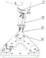
图1a是本发明一实施例中一种工业机器人分步式标定系统的结构示意图;1a is a schematic structural diagram of a step-by-step calibration system for an industrial robot according to an embodiment of the present invention;
图1b是图1a中A区域的局部放大示意图;Fig. 1b is a partial enlarged schematic diagram of area A in Fig. 1a;
图2是本发明一实施例中一种工业机器人分步式标定方法的第一步标定示意图;2 is a schematic diagram of the first step calibration of a step-by-step calibration method for an industrial robot in an embodiment of the present invention;
图3a、图3b分别是本发明一实施例中一种工业机器人分步式标定方法中距离误差(第一步标定)、位置误差(第二步标定)测量的原理示意图;Fig. 3a, Fig. 3b are respectively the principle schematic diagram of the distance error (the first step of calibration) and the position error (the second step of the calibration) measurement in a step-by-step calibration method for an industrial robot in an embodiment of the present invention;
图4是本发明一实施例中双球装置中精密钢球与锥形球座的安装示意图;Fig. 4 is the installation schematic diagram of the precision steel ball and the conical ball seat in the double ball device in one embodiment of the present invention;
图5是本发明一实施例中末端测量装置的精密钢球球心坐标的测量算法流程图;5 is a flow chart of the measurement algorithm of the precision steel ball spherical center coordinates of the end measurement device in an embodiment of the present invention;
图6、图7分别是本发明一实施例中一种工业机器人分步式标定方法中一次标定、二次标定的流程图;FIG. 6 and FIG. 7 are respectively the flowcharts of primary calibration and secondary calibration in a step-by-step calibration method for an industrial robot according to an embodiment of the present invention;
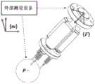
图8是本发明一实施例中末端测量装置的一种几何参数标定方法中测量原理的示意图;8 is a schematic diagram of a measurement principle in a geometric parameter calibration method of an end measurement device in an embodiment of the present invention;
图9是本发明一实施例中末端测量装置的一种几何参数标定方法的流程图;9 is a flow chart of a method for calibrating geometric parameters of an end measurement device in an embodiment of the present invention;
附图标记说明:末端测量装置1、机器人2、双球装置3、磁性表座4、精密钢球5、工作台6、三球座装置7、通讯线缆8、通讯线缆9、计数器10、通讯线缆11、计算机12、底板13、精密钢球14、测针15、位移传感器16、机器人法兰17、永磁体18、锥形球座19。Description of reference numerals: end
具体实施方式Detailed ways
以下结合实施例与附图对本发明作进一步详细描述,需要指出的是,以下实施例旨在便于对本发明的理解,而对其不起任何限定作用。The present invention will be further described in detail below with reference to the embodiments and the accompanying drawings. It should be noted that the following embodiments are intended to facilitate the understanding of the present invention, but do not have any limiting effect on it.
本发明实施例的一个方面提供了一种工业机器人分步式标定系统,其可以参阅图1a-图1b所示,其包括可移动的双球装置3、固定的三球座装置7、末端测量装置1、计算机12、计数器10等。One aspect of the embodiments of the present invention provides a step-by-step calibration system for an industrial robot, which can be referred to as shown in FIGS. 1 a to 1 b , which includes a movable
进一步的,所述双球装置3、三球座装置7和机器人2的基座均设置在一工作台6的台面上。并且,所述双球装置3可以相对于机器人2基座移动并被锁止在机器人2工作空间内的任意指定位置,而所述三球座装置7与机器人2基座相对固定设置。Further, the bases of the double-
进一步的,所述双球装置3可以通过磁性表座4的磁吸力安装于工作台6的台面上,方便于移动并安装至机器人工作空间内的不同位置。Further, the
进一步的,所述三球座装置7固定于工作台6,其位置相对于机器人基座标系固定不变。Further, the three-
进一步的,所述末端测量装置1安装于机器人法兰16上。Further, the
进一步的,所述末端测量装置1、计算机12、计数器10、机器人2之间可以通过有线或无线方式连接,例如可以采用图1a所示方式,分别通过通讯线缆8、9、11相互连接。Further, the
请继续参阅图1a、图1b、图3b,所述三球座装置7包括三个精密钢球14、三个锥形球座19;各精密钢球14是通过永磁体18的磁吸力安装于锥形球座19。所述三个锥形球座19安装在三角形底板上,该底板可以通过紧固螺钉等与前述工作台6固定连接。Please continue to refer to FIGS. 1 a , 1 b and 3 b , the three-
请继续图1a、图2、图3a及图4,所述双球装置3包括两个精密钢球5和两个锥形球座;各精密钢球5也可以是通过永磁体的磁吸力安装于相应锥形球座。所述两个锥形球座安装在条形底板上,该底板可以通过紧固螺钉等与一磁性表座4固定连接,并通过所述磁性表座4的磁力作用吸附在前述工作台6上。Please continue to Fig. 1a, Fig. 2, Fig. 3a and Fig. 4, the
进一步的,所述精密钢球5、14的精度为G5级别以上。Further, the precision of the
进一步的,所述末端测量装置1包括三个相隔120°均匀分布的位移传感器16和三个具有球形测头的测针15;每一测针安装于相应位移传感器16的测量端;当测针15接触双球装置3及三球座装置7中的待测精密钢球时,测针15的球形测头的球心可产生轴向位移。Further, the
进一步的,请参阅图2及图4,所述双球装置3的两颗精密钢球5的球心P11、P12的球心距||P11P12||=la为定值。通过所述磁性表座4与工作台6之间的磁吸力的开关,双球装置3可移动并安装至全局机器人工作空间内的不同位置,例如图2所示的位置1、位置2,但不限于此。Further, please refer to FIG. 2 and FIG. 4 , the center-to-center distance ||P11 P12 ||=la of the two
进一步的,所述三球座装置7的3颗精密钢球14的球心位置分布定义了世界坐标系{w};该世界坐标系{w}与基坐标系{0}之间的初始位姿变换矩阵可以根据两者的位置安装关系得到;在世界坐标系{w}下,3颗精密钢球14的实际球心坐标分别表示为P1、P2、P3。Further, the position distribution of the ball centers of the three
进一步的,所述的末端测量装置1将位移传感器15的测量信息通过计数器10发送至计算机12,以及,所述计算机12采集机器人的关节角信息;Further, the
所述计算机12根据采集的位移传感器的测量信息及机器人关节角信息,计算所述双球装置中两个精密钢球5的理论球心坐标及所述三球座装置中各个精密钢球14的理论球心坐标;The
继而,所述计算机12根据得到的所述双球装置3、三球座装置7中各精密钢球的理论球心坐标分别计算机器人末端在机器人广域工作空间中两点的距离误差及机器人末端的位置误差,并将其代入分步式标定算法,求解机器人运动学误差参数。Then, the
进一步的,在所述计算机12可以设置多个功能模块,例如第一模块、第二模块、第三模块、第四模块。其中,第一模块用于获取机器人的关节角信息。第二模块用于获取计数器发送的位移测量信息。第三模块则用于根据采集的位移传感器的测量信息及机器人关节角信息,计算所述双球装置中两个精密钢球的理论球心坐标及所述三球座装置中各个精密钢球的理论球心坐标。第四模块用于根据得到的所述双球装置、三球座装置中各精密钢球的理论球心坐标分别计算机器人末端在机器人广域工作空间中两点的距离误差及机器人末端的位置误差,并将其代入分步式标定算法,求解机器人运动学误差参数。Further, a plurality of functional modules may be set in the
其中,所述分步式标定算法可以主要基于最小二乘法和循环迭代流程建立。Wherein, the step-by-step calibration algorithm can be established mainly based on the least squares method and the loop iteration process.
相应地,本实施例的另一个方面还提供了基于前述工业机器人分步式标定系统的一种工业机器人分步式标定方法,其可以包括两次标定流程,即:Correspondingly, another aspect of this embodiment also provides a step-by-step calibration method for an industrial robot based on the aforementioned industrial robot step-by-step calibration system, which may include two calibration processes, namely:
第一步标定(亦称一次标定):利用机器人广域工作空间内的距离误差对机器人自身运动学参数标定;The first step of calibration (also known as one-time calibration): use the distance error in the robot's wide-area workspace to calibrate the kinematic parameters of the robot itself;
第二步标定(亦称二次标定):利用机器人的位置误差对一次标定后的机器人的基坐标系的位姿进行标定。The second step of calibration (also known as secondary calibration): use the position error of the robot to calibrate the pose of the base coordinate system of the robot after the first calibration.
进一步的,所述标定方法还可以包括:在进行所述一次标定和二次标定之前,先对末端测量装置进行标定。具体的,可以在初次使用所述工业机器人分步式标定系统对机器人进行分步式标定时,对所述末端测量装置自身的几何参数进行标定,以补偿末端测量装置对待测钢球的球心坐标的测量误差,进而进一步提高所述工业机器人分步式标定方法的精度。Further, the calibration method may further include: before performing the primary calibration and the secondary calibration, calibrating the end measurement device. Specifically, when the industrial robot step-by-step calibration system is used to perform step-by-step calibration of the robot for the first time, the geometric parameters of the end measuring device itself can be calibrated to compensate the center of the steel ball to be measured by the end measuring device. The measurement error of the coordinates is further improved, and the accuracy of the step-by-step calibration method of the industrial robot is further improved.
进一步的,参阅图6、图7、图8、图9,所述工业机器人分步式标定方法具体包括:Further, referring to Fig. 6, Fig. 7, Fig. 8, Fig. 9, the step-by-step calibration method of the industrial robot specifically includes:
参阅图6所示是第一步标定方法流程,包括:Refer to Figure 6 for the first step of calibration method flow, including:
S1:采用局部指数积(Local POE)公式建立在机器人2的基坐标系{0}下描述的正向运动学模型,得到包含理论运动学参数的位姿变换矩阵T0,n+1。S1: The forward kinematics model described in the base coordinate system {0} of the
S2:根据步骤S1建立的机器人2的正向运动学模型,建立机器人2的末端距离误差模型,即末端距离误差δl与机器人初始位姿误差δt之间的映射关系:δl=G(δt1,δt2...,δtn,δtn+1),可进一步写作一种线性的形式:δP=J1[δt1,δt2...,δtn,δtn+1]T,其中,误差雅可比矩阵J1是机器人自身运动学误差δt与机器人末端距离误差δl之间的误差传递矩阵。S2: According to the forward kinematics model of the
S3:控制机器人移动至指定位置,使末端测量装置的三个测针15同时接触双球装置3两端的精密钢球5,确保末端测量装置中位移传感器上的三个测针的球形测头均产生位移,采集此时位移传感器的测量信息K与机器人关节角信息q。S3: Control the robot to move to the designated position, so that the three
S4:根据步骤S3采集的位移传感器的测量信息K计算出前述精密钢球5的球心相对于机器人法兰坐标系{F}的位置坐标,再根据步骤S1建立的位姿变换矩阵T0,n+1与步骤S3采集的关节角信息q,计算出双球装置3中各精密钢球5的理论球心距ln,与这些精密钢球5的实际球心距la作差,得到机器人末端误差δl。S4: Calculate the position coordinates of the center of the
参阅图5所示是前述精密钢球5、14的球心坐标测量算法流程。例如,步骤S4中利用前述测量信息K计算精密钢球5、14的球心相对于机器人法兰坐标系{F}的位置坐标的方法如下:Referring to FIG. 5 , the algorithm flow of the spherical center coordinate measurement of the aforementioned
设定末端测量装置1中三个测针的球形测头的球心相对于机器人法兰坐标系{F}的初始坐标为p0i=[ai,bi,ci],i=1,2,3;Set the initial coordinates of the ball centers of the spherical probes of the three styluses in the
设定前述三个测针接触精密钢球5、14时位移传感器的测量值为K=[k1,k2,k3],则此时三个球形测头的球心坐标可以分别写作pi=[ai,bi,ci-ki],i=1,2,3;因此,三球座装置中待测精密钢球14的球心坐标pT=[x,y,z]可以通过求解如下三元二次方程组得到Assuming that the measurement value of the displacement sensor when the aforementioned three styluses contact the
(ai-x)2+(bi-y)2+(ci-ki-z)2=(r+R)2,i=1,2,3 (1)其中,R为精密钢球14的半径;r为测针15的球形测头的半径。对式(1)进行求解,可得到pT的2组解:pT1=[x1,y1,z1]、pT2=[x2,y2,z2],最后再根据三个球形测头的球心坐标s1、s2、s3,可建立三个球形测头球心点所在的平面的方程:(ai -x)2 +(bi -y)2 +(ci -k i-z )2 =(r+R)2 , i=1, 2, 3 (1) Wherein, R is precision steel The radius of the
Ax+By+Cz+D=0 (2)Ax+By+Cz+D=0 (2)
其中,根据三点确定平面的准则,可得Among them, according to the criterion of three points to determine the plane, we can get

将求得的2组解pT1、pT2分别代入式(3),选择其中Ax+By+Cz+D>0的1组解,该解即代表精密钢球5、14的球心在机器人法兰坐标系{F}下的准确坐标。Substitute the obtained two sets of solutions pT1 and pT2 into formula (3) respectively, and select one set of solutions in which Ax+By+Cz+D>0, which means that the centers of the
S5:利用磁性表座4的可开关磁吸力,将双球装置安装于大范围机器人工作空间内的不同位置,并重复步骤S3、S4的操作,采集足够、广域的机器人距离误差信息。S5: Using the switchable magnetic attraction of the magnetic table base 4, install the double-ball device at different positions in the large-scale robot workspace, and repeat the operations of steps S3 and S4 to collect enough and wide-area robot distance error information.
S6:根据步骤S2建立的所述机器人2的末端距离误差模型,利用最小二乘法


参阅图7所示是第二步标定方法流程,包括:Referring to Figure 7, it is the second step of the calibration method flow, including:
S7:延长机器人运动链至世界坐标系{w},采用局部指数积(Local POE)公式建立描述于所述世界坐标系{w}下的机器人的正向运动学模型,得到从所述世界坐标系{w}到机器人工具坐标系{n+1}位姿变换矩阵Tw,n+1,机器人自身运动学参数ti采用一次标定后得到的结果。S7: Extend the kinematic chain of the robot to the world coordinate system {w}, use the local exponential product (Local POE) formula to establish the forward kinematics model of the robot described in the world coordinate system {w}, and obtain from the world coordinate system system {w} to the robot tool coordinate system {n+1} pose transformation matrix Tw, n+1 , the kinematic parameter ti of the robot itself is the result obtained after one calibration.
S8:根据机器人2的一次标定后运动学模型(即步骤S7建立的机器人正向运动学模型),建立描述于所述世界坐标系{w}下的机器人位置误差模型,即末端位置误差δP与机器人基坐标系{0}位姿误差δtw之间的映射关系:δP=F(δtw),可进一步写作:δP=J2δtw。其中,误差雅可比矩阵J2是基坐标系位姿误差δtw与机器人末端位置误差之间的传递矩阵。S8: According to the post-calibration kinematics model of the robot 2 (that is, the forward kinematics model of the robot established in step S7), establish a robot position error model described in the world coordinate system {w}, that is, the end position error δP and The mapping relationship between the robot base coordinate system {0} pose errors δtw : δP=F(δtw ), which can be further written as: δP=J2 δtw . Among them, the error Jacobian matrix J2 is the transfer matrix between the base coordinate system pose error δtw and the robot end position error.
S9:控制机器人移动至指定位置,使末端测量装置的三个测针15同时接触三球座装置7的各个精密钢球14,采集此时的位移传感器的测量信息K与机器人关节角信息q。S9: control the robot to move to a specified position, make the three
S10:根据步骤S9中采集的位移传感器的测量信息K计算出各精密钢球14的球心相对于机器人法兰坐标系{F}的位置坐标,计算流程同步骤S4,再根据建立的前述标定后运动学模型Tw,n+1与步骤S9中采集的关节角信息q,计算出三球座装置中各精密钢球14的理论球心坐标
S11:根据步骤S8建立的所述机器人位置误差模型,利用最小二乘法


进一步的,所述标定方法还可以包括:Further, the calibration method can also include:
S12:将前述两步标定(步骤S1-步骤S11)计算得到的运动学参数补偿到实际机器人系统,提高其绝对定位精度。S12: Compensate the kinematic parameters calculated by the foregoing two-step calibration (step S1-step S11) to the actual robot system to improve its absolute positioning accuracy.
进一步的,在前述步骤S1中,采用局部指数积公式建立机器人(2)在基坐标系{0}下描述的运动学模型,表示为:Further, in the aforementioned step S1, the local exponential product formula is used to establish the kinematic model of the robot (2) described in the base coordinate system {0}, which is expressed as:

其中,0P与FP分别代表球心坐标在世界坐标系{0}与法兰坐标系{F}下的表示,


进一步的,在前述步骤S2中,建立的所述机器人末端距离误差模型的误差参数为机器人本体的连杆初始位姿误差δti,误差雅克比矩阵如下所示:Further, in the aforementioned step S2, the error parameter of the established robot end distance error model is the initial pose error δti of the connecting rod of the robot body, and the error Jacobian matrix is as follows:

其中,R0,i代表坐标系{i}相对于坐标系{0}的姿态,
进一步的,在前述步骤S2中,建立的所述机器人末端距离误差模型可以写作y=J1x的形式,为了获取足够的信息,以辨识所有运动学误差参数ti,可以对双球装置的精密钢球5进行m(m>6n+6)次测量实验,当测得m组数据时,得到扩展后的误差模型
进一步的,在前述步骤S7中,采用局部指数积公式建立机器人(2)在世界坐标系{w}下描述的运动学模型,表示为:Further, in the aforementioned step S7, the local exponential product formula is used to establish the kinematic model of the robot (2) described in the world coordinate system {w}, which is expressed as:

其中,wP是三球装置中三个精密钢球的球心坐标在所述世界坐标系{w}下的表示,
进一步的,在前述步骤S8中,建立的描述于世界坐标系{w}下的机器人位置误差模型的误差参数为机器人基坐标系的转换误差δtw;误差雅克比矩阵如下所示:Further, in the aforementioned step S8, the established error parameter of the robot position error model described in the world coordinate system {w} is the transformation error δtw of the robot base coordinate system; the error Jacobian matrix is as follows:

其中,R0,i代表坐标系{0}相对于坐标系{w}的姿态。Among them, R0,i represents the pose of coordinate system {0} relative to coordinate system {w}.
进一步的,在前述步骤S8中,建立的描述于世界坐标系{w}下的机器人位置误差模型可以写作y=J2x的形式,为了获取足够的信息,以准确辨识机器人基坐标系位姿参数tw,可以对三个精密钢球14进行m(m>2)次测量实验,当测得m组数据时,得到扩展后的误差模型
概括的讲,在前述标定方法中,是基于前述的整套标定系统,在第一步标定中利用机器人广域工作空间内的距离误差标定机器人自身连杆运动学参数ti,在第二步标定中利用位置误差标定,基于第一步标定的结果,对机器人基座标系位姿参数tw进行标定。Generally speaking, in the aforementioned calibration method, based on the aforementioned whole set of calibration system, in the first step of calibration, the distance error in the robot's wide-area workspace is used to calibrate the kinematic parameter ti of the robot's own linkage, and in the second step of calibration. The position error calibration is used in , and based on the result of the first step calibration, the pose parameter tw of the robot base frame is calibrated.
进一步的,在前述步骤S5中,应尽量将双球装置3在不同位置移动,使其均匀地安装于全局机器人工作空间内不同位置,以采集机器人广域工作空间内的距离误差,进而提高误差参数求解的精度和可靠性。Further, in the aforementioned step S5, the double-
进一步的,在前述步骤S4、S9中,机器人测量钢球5、14时的位姿应尽量不同,均匀分布于机器人的位型空间,提高测量结构多样性,进而提高标定结果的可靠性。Further, in the aforementioned steps S4 and S9, the poses of the robot when measuring the
进一步的,在前述步骤S5、S10中,应选取数值相对较大的测量结果,保证末端测量装置测量得到的机器人距离误差的绝对值和位置误差的模长大于待标定机器人自身重复定位精度的大小,进一步提高机器人误差信号的信噪比。Further, in the aforementioned steps S5 and S10, a measurement result with a relatively large value should be selected to ensure that the absolute value of the distance error of the robot and the modulus length of the position error measured by the terminal measuring device are greater than the size of the repetitive positioning accuracy of the robot to be calibrated itself. , to further improve the signal-to-noise ratio of the robot error signal.
进一步的,在前述步骤S6、S11中,检查误差雅可比矩阵J1、J2是否奇异,若出现奇异,则需要重新选择机器人位姿进行误差测量,以提高标定算法的收敛性。Further, in the aforementioned steps S6 and S11, it is checked whether the error Jacobian matrices J1 , J2 are singular. If singular, the robot pose needs to be reselected for error measurement to improve the convergence of the calibration algorithm.
为了进一步提高步骤S4、S10中的距离误差及位置误差的测量精度,可以在进行所述一次标定和二次标定之前,特别是所述双球装置、三球座装置在初次正式投入使用之前,以光学三坐标测量仪等精密测量设备测量双球装置中各精密钢球的实际球心距及球心坐标的精确值以及三球座装置中各精密钢球的实际球心距及球心坐标的精确值。In order to further improve the measurement accuracy of the distance error and position error in steps S4 and S10, before the primary calibration and the secondary calibration are performed, especially before the double-ball device and the three-ball seat device are officially put into use for the first time, Measure the actual center-to-center distance and the exact value of the center-to-center coordinates of each precision steel ball in the double-ball device, and the actual center-to-center distance and center coordinates of each precision steel ball in the three-ball seat device with precision measuring equipment such as an optical three-coordinate measuring instrument exact value.
为进一步提升前述标定方法的实际应用精度,还可以在初次使用所述标定系统对机器人进行标定时,先利用光学三坐标测量仪、激光扫描仪等外部的非接触式精密测量设备获取末端测量装置的测量误差,对所述末端测量装置自身的几何参数进行标定,其过程包括:建立所述末端测量装置的误差模型及其标定算法,实现对末端测量装置几何参数δp0i的标定,进而提高其对所述双球装置、三球座装置中各精密钢球球心的测量精度。In order to further improve the practical application accuracy of the aforementioned calibration method, when the robot is calibrated using the calibration system for the first time, an external non-contact precision measuring device such as an optical three-coordinate measuring instrument and a laser scanner can be used to obtain the end measuring device. The measurement error of the terminal measurement device itself is calibrated, and the process includes: establishing an error model of the terminal measurement device and its calibration algorithm, realizing the calibration of the geometric parameters of the terminal measurement device δp0i , and then improving its The measurement accuracy of the center of each precision steel ball in the double-ball device and the three-ball seat device.
参阅图9所示,对末端测量装置几何参数标定的流程可以包括:Referring to Figure 9, the process of calibrating the geometric parameters of the end measurement device may include:
S13:利用微分法,对步骤S4中的三元二次方程组(1)的等式两边进行微分,建立一种末端测量装置的误差模型,即末端测量装置对各精密钢球球心的坐标测量误差δFP与末端测量装置几何参数误差δp0i之间的映射关系,可以表示为δFP=M(δp0i)或δFP=J3δp0i,其中,误差雅可比矩阵J3是所述末端测量装置几何参数误差与球心坐标测量误差δFP之间的传递矩阵。末端测量装置几何参数误差δp0i=[δai,δbi,δci],(i=1,2,3),代表所述测量装置的3个球形测头的球心坐标在法兰坐标系{F}下初始坐标的误差。S13: Differentiate both sides of the equation of the quadratic equation (1) in step S4 by using the differential method to establish an error model of the end measuring device, that is, the coordinates of the center of each precision steel ball by the end measuring device The mapping relationship between the measurement error δF P and the geometric parameter error δp0i of the end measurement device can be expressed as δF P=M(δp0i ) or δFP =J3 δp0i , where the error Jacobian matrix J3 is the transfer matrix between the geometric parameter error of the end measurement device and the spherical center coordinate measurement error δF P. The geometric parameter error of the end measuring device δp0i = [δai , δbi , δci ], (i =1, 2, 3), representing the spherical center coordinates of the three spherical probes of the measuring device in the flange coordinate system Error in initial coordinates under {F}.
S14:参阅图8所示是末端测量装置的一种几何参数标定方法中的测量原理。在末端测量装置处于未安装于机器人法兰状态下,操纵末端测量装置使其三个测针同时接触三球座装置中的某一精密钢球,采集此时末端测量装置的三个位移传感器的测量信息K与机器人关节角信息q。同时,使用非接触式外部精密测量设备(如光学三坐标测量仪、激光扫描仪等)测量此时该精密钢球球心相对于末端测量装置的法兰坐标系{F}的实际位置坐标FPa。S14: Referring to Fig. 8, the measurement principle is shown in a geometric parameter calibration method of the end measurement device. When the end measuring device is not installed on the robot flange, manipulate the end measuring device to make the three stylus contact a certain precision steel ball in the three-ball seat device at the same time, and collect the three displacement sensors of the end measuring device at this time. Measurement information K and robot joint angle information q. At the same time, use non-contact external precision measuring equipment (such as optical three-coordinate measuring instrument, laser scanner, etc.) to measure the actual position coordinateF of the center of the precision steel ball relative to the flange coordinate system{F}of the end measuring device.Pa .
S15:根据步骤S14采集的信息K和q,计算出该精密钢球的球心相对于法兰坐标系{F}的位置坐标理论位置坐标FPn,与步骤S14采集的实际位置坐标FPa作差,可以得到测量装置的对该精密钢球球心坐标的测量误差δFP。S15: According to the information K and q collected in step S14, calculate the position coordinate theoretical position coordinateF Pn of the center of the precision steel ball relative to the flange coordinate system {F}, which is the same as the actual position coordinateF P collected in step S14 By making the difference ofa , the measurement error δF P of the spherical center coordinate of the precision steel ball of the measuring device can be obtained.
S16:根据步骤S13建立的所述测量装置的误差模型,利用最小二乘法和循环迭代的流程构建测量装置几何参数的标定算法,将步骤S15获得的该精密钢球球心坐标的测量误差δFP代入该算法,利用最小二乘法解算末端测量装置几何参数误差δp0i,再利用式p0inew=p0iold+δp0i更新末端测量装置的几何参数,重复迭代,直至球心坐标测量误差向量δFP的模长
进一步的,在前述步骤S13中,建立的末端测量装置误差模型的误差参数为该末端测量装置的3个球形测头的球心坐标在法兰坐标系{F}下初始坐标的误差δp0i=[δai,δbi,δci],(i=1,2,3);误差雅克比矩阵如下所示:Further, in the aforementioned step S13, the error parameter of the established end measurement device error model is the error δp0i = the initial coordinates of the spherical center coordinates of the three spherical probes of the end measurement device in the flange coordinate system {F}. [δai , δbi , δci ], (i=1, 2, 3); the error Jacobian matrix is as follows:

其中,矩阵A和B均为与末端测量装置几何参数相关的系数矩阵,Among them, matrices A and B are both coefficient matrices related to the geometric parameters of the end measurement device,

进一步的,在前述步骤S13中,建立的描述于法兰坐标系{F}下的末端测量装置的误差模型可以写作y=J3x的形式,为了获取足够的信息,以准确辨识末端测量装置的几何参数p0i,可以对所述标定系统中的一个精密钢球进行m(m>3)次测量实验,当测得m组数据时,得到扩展后的误差模型
进一步的,在前述步骤S15中,优选使所述末端测量装置以多个不同姿态测量某一精密钢球的球心,并使所述3个位移位移传感器之间采集的数据的数值大小尽可能不同。Further, in the aforementioned step S15, it is preferable to make the end measurement device measure the center of a precision steel ball with a plurality of different attitudes, and to make the numerical value of the data collected between the three displacement sensors as large as possible. different.
本发明以上实施例提供的标定系统具有便携、成本低等优点,提供的标定方法通过分步式标定,提高了机器人运动学误差标定的精度和可靠性,同时实现机器人基座坐标系的标定,进而提高了机器人的绝对定位精度,可以极大地拓宽机器人在精密制造领域的应用。The calibration system provided by the above embodiments of the present invention has the advantages of portability, low cost, etc. The provided calibration method improves the accuracy and reliability of the robot kinematic error calibration through step-by-step calibration, and simultaneously realizes the calibration of the robot base coordinate system. In turn, the absolute positioning accuracy of the robot is improved, and the application of the robot in the field of precision manufacturing can be greatly expanded.
应当理解,本发明的技术方案不限于上述具体实施案例的限制,凡是在不脱离本发明宗旨和权利要求所保护的范围情况下,根据本发明的技术方案做出的技术变形,均落于本发明的保护范围之内。It should be understood that the technical solutions of the present invention are not limited to the limitations of the above-mentioned specific implementation cases, and all technical deformations made according to the technical solutions of the present invention without departing from the scope of the invention and the scope of protection of the claims fall within the scope of the present invention. within the scope of protection of the invention.
Claims (10)
Translated fromChinese


Priority Applications (1)
| Application Number | Priority Date | Filing Date | Title |
|---|---|---|---|
| CN202011573381.4ACN112847341B (en) | 2020-12-25 | 2020-12-25 | Industrial robot step-by-step calibration system and method |
Applications Claiming Priority (1)
| Application Number | Priority Date | Filing Date | Title |
|---|---|---|---|
| CN202011573381.4ACN112847341B (en) | 2020-12-25 | 2020-12-25 | Industrial robot step-by-step calibration system and method |
Publications (2)
| Publication Number | Publication Date |
|---|---|
| CN112847341Atrue CN112847341A (en) | 2021-05-28 |
| CN112847341B CN112847341B (en) | 2024-02-02 |
Family
ID=75997493
Family Applications (1)
| Application Number | Title | Priority Date | Filing Date |
|---|---|---|---|
| CN202011573381.4AActiveCN112847341B (en) | 2020-12-25 | 2020-12-25 | Industrial robot step-by-step calibration system and method |
Country Status (1)
| Country | Link |
|---|---|
| CN (1) | CN112847341B (en) |
Cited By (12)
| Publication number | Priority date | Publication date | Assignee | Title |
|---|---|---|---|---|
| CN113618738A (en)* | 2021-08-23 | 2021-11-09 | 上海大学 | Mechanical arm kinematic parameter calibration method and system |
| CN113733102A (en)* | 2021-10-08 | 2021-12-03 | 厦门大学 | Error calibration device and method for industrial robot |
| CN113878586A (en)* | 2021-11-04 | 2022-01-04 | 上海景吾智能科技有限公司 | Robot kinematics calibration device, method and system |
| CN113894791A (en)* | 2021-11-05 | 2022-01-07 | 佛山非夕机器人科技有限公司 | Kinematics calibration method and system of multi-degree-of-freedom robot |
| CN114012719A (en)* | 2021-10-22 | 2022-02-08 | 上海发那科机器人有限公司 | Zero calibration method and system for six-axis robot |
| CN114524028A (en)* | 2022-02-18 | 2022-05-24 | 中国航空制造技术研究院 | Crawling robot motion parameter calibration and posture adjustment method |
| CN115319726A (en)* | 2022-08-15 | 2022-11-11 | 中国科学院宁波材料技术与工程研究所 | A Robot Calibration Method Based on Position and Distance Constraints |
| WO2023040095A1 (en)* | 2021-09-16 | 2023-03-23 | 梅卡曼德(北京)机器人科技有限公司 | Camera calibration method and apparatus, electronic device, and storage medium |
| WO2024037174A1 (en)* | 2022-08-15 | 2024-02-22 | 中国科学院宁波材料技术与工程研究所 | Robot calibration method based on pose constraint and force sensing |
| CN117663989A (en)* | 2024-01-29 | 2024-03-08 | 湖南盛势通科技有限公司 | A scanning ranging positioning system and method |
| CN117718800A (en)* | 2024-01-18 | 2024-03-19 | 西北工业大学 | Standard device and calibration method for calibrating multisource integrated errors of on-machine measurement system |
| US12194642B2 (en) | 2021-11-05 | 2025-01-14 | Foshan Flexiv Robotics Technology Co, . Ltd. | Kinematics calibration method and calibration system for robot with multiple degrees of freedom |
Citations (6)
| Publication number | Priority date | Publication date | Assignee | Title |
|---|---|---|---|---|
| KR20120018933A (en)* | 2010-08-24 | 2012-03-06 | 한국과학기술원 | Estimation system for kinetic parameter of robot manipulator and method therefor |
| CN104858870A (en)* | 2015-05-15 | 2015-08-26 | 江南大学 | Industrial robot measurement method based on tail end numbered tool |
| WO2017033100A1 (en)* | 2015-08-26 | 2017-03-02 | Tyco Electronics (Shanghai) Co. Ltd | Automatic calibration method for robot system |
| CN107042528A (en)* | 2017-06-01 | 2017-08-15 | 中国科学院宁波材料技术与工程研究所 | A kind of Kinematic Calibration system and method for industrial robot |
| CN111660295A (en)* | 2020-05-28 | 2020-09-15 | 中国科学院宁波材料技术与工程研究所 | Industrial robot absolute precision calibration system and calibration method |
| CN112091971A (en)* | 2020-08-21 | 2020-12-18 | 季华实验室 | Robot eye calibration method and device, electronic equipment and system |
- 2020
- 2020-12-25CNCN202011573381.4Apatent/CN112847341B/enactiveActive
Patent Citations (6)
| Publication number | Priority date | Publication date | Assignee | Title |
|---|---|---|---|---|
| KR20120018933A (en)* | 2010-08-24 | 2012-03-06 | 한국과학기술원 | Estimation system for kinetic parameter of robot manipulator and method therefor |
| CN104858870A (en)* | 2015-05-15 | 2015-08-26 | 江南大学 | Industrial robot measurement method based on tail end numbered tool |
| WO2017033100A1 (en)* | 2015-08-26 | 2017-03-02 | Tyco Electronics (Shanghai) Co. Ltd | Automatic calibration method for robot system |
| CN107042528A (en)* | 2017-06-01 | 2017-08-15 | 中国科学院宁波材料技术与工程研究所 | A kind of Kinematic Calibration system and method for industrial robot |
| CN111660295A (en)* | 2020-05-28 | 2020-09-15 | 中国科学院宁波材料技术与工程研究所 | Industrial robot absolute precision calibration system and calibration method |
| CN112091971A (en)* | 2020-08-21 | 2020-12-18 | 季华实验室 | Robot eye calibration method and device, electronic equipment and system |
Non-Patent Citations (1)
| Title |
|---|
| GU L: "A Two-Step Self-calibration Method with Portable Measurement Devices for Industrial Robots Based on POE Formula", INTERNATIONAL CONFERENCE ON INTELLIGENT ROBOTICS AND APPLICATIONS. SPRINGER, CHAM, 2019, pages 715 - 726* |
Cited By (17)
| Publication number | Priority date | Publication date | Assignee | Title |
|---|---|---|---|---|
| CN113618738B (en)* | 2021-08-23 | 2024-04-19 | 上海大学 | Mechanical arm kinematics parameter calibration method and system |
| CN113618738A (en)* | 2021-08-23 | 2021-11-09 | 上海大学 | Mechanical arm kinematic parameter calibration method and system |
| WO2023040095A1 (en)* | 2021-09-16 | 2023-03-23 | 梅卡曼德(北京)机器人科技有限公司 | Camera calibration method and apparatus, electronic device, and storage medium |
| CN113733102A (en)* | 2021-10-08 | 2021-12-03 | 厦门大学 | Error calibration device and method for industrial robot |
| CN113733102B (en)* | 2021-10-08 | 2022-12-16 | 厦门大学 | Error calibration device for industrial robot |
| CN114012719B (en)* | 2021-10-22 | 2024-04-16 | 上海发那科机器人有限公司 | Zero calibration method and system for six-axis robot |
| CN114012719A (en)* | 2021-10-22 | 2022-02-08 | 上海发那科机器人有限公司 | Zero calibration method and system for six-axis robot |
| CN113878586A (en)* | 2021-11-04 | 2022-01-04 | 上海景吾智能科技有限公司 | Robot kinematics calibration device, method and system |
| CN113894791A (en)* | 2021-11-05 | 2022-01-07 | 佛山非夕机器人科技有限公司 | Kinematics calibration method and system of multi-degree-of-freedom robot |
| US12194642B2 (en) | 2021-11-05 | 2025-01-14 | Foshan Flexiv Robotics Technology Co, . Ltd. | Kinematics calibration method and calibration system for robot with multiple degrees of freedom |
| CN114524028B (en)* | 2022-02-18 | 2023-02-28 | 中国航空制造技术研究院 | Motion parameter calibration and posture adjustment method for crawling robot |
| CN114524028A (en)* | 2022-02-18 | 2022-05-24 | 中国航空制造技术研究院 | Crawling robot motion parameter calibration and posture adjustment method |
| WO2024037174A1 (en)* | 2022-08-15 | 2024-02-22 | 中国科学院宁波材料技术与工程研究所 | Robot calibration method based on pose constraint and force sensing |
| CN115319726A (en)* | 2022-08-15 | 2022-11-11 | 中国科学院宁波材料技术与工程研究所 | A Robot Calibration Method Based on Position and Distance Constraints |
| US12263602B1 (en) | 2022-08-15 | 2025-04-01 | Ningbo Institute Of Materials Technology And Engineering, Chinese Academy Of Sciences | Robot calibration method based on pose constraint and force sensing |
| CN117718800A (en)* | 2024-01-18 | 2024-03-19 | 西北工业大学 | Standard device and calibration method for calibrating multisource integrated errors of on-machine measurement system |
| CN117663989A (en)* | 2024-01-29 | 2024-03-08 | 湖南盛势通科技有限公司 | A scanning ranging positioning system and method |
Also Published As
| Publication number | Publication date |
|---|---|
| CN112847341B (en) | 2024-02-02 |
Similar Documents
| Publication | Publication Date | Title |
|---|---|---|
| CN112847341B (en) | Industrial robot step-by-step calibration system and method | |
| CN111660295B (en) | Industrial robot absolute precision calibration system and calibration method | |
| CN109304730B (en) | Robot kinematic parameter calibration method based on laser range finder | |
| CN107042528B (en) | Kinematics calibration system and method for industrial robot | |
| CN110978059B (en) | A portable six-axis manipulator calibration device and calibration method thereof | |
| WO2021179460A1 (en) | Laser light exit direction calibration method employing standard ball | |
| CN109676636A (en) | A kind of industrial robot kinematics calibration system and scaling method | |
| CN102706277B (en) | Industrial robot online zero position calibration device based on all-dimensional point constraint and method | |
| CN106393174B (en) | A method of demarcating robot architecture's parameter using ball bar | |
| CN109822574A (en) | A method for calibrating a six-dimensional force sensor at the end of an industrial robot | |
| CN102654387B (en) | Online industrial robot calibration device based on spatial curved surface restraint | |
| CN105058387A (en) | Industrial robot base coordinate system calibration method based on laser tracker | |
| CN115284079B (en) | Magnetorheological polishing calibration method | |
| CN112277002B (en) | Robot kinematics calibration device and calibration method based on incomplete pose information | |
| CN113618738B (en) | Mechanical arm kinematics parameter calibration method and system | |
| CN113146613A (en) | Three-dimensional self-calibration device and method for D-H parameters of industrial robot | |
| CN114571436B (en) | Robot external parameter calibration method independent of ground rail absolute precision | |
| CN115371564B (en) | Method and system for calibrating relative pose between line laser sensor and robot flange | |
| Fares et al. | Tool center point calibration method for an industrial robots based on spheres fitting method | |
| CN113878586B (en) | Robot kinematics calibration device, method and system | |
| Zhao et al. | Robust geometry self-calibration based on differential kinematics for a redundant robotic inspection system | |
| CN115503022A (en) | Robot measurement configuration determining method based on multi-station measurement | |
| CN108344382B (en) | Digitlization snap-gauge and its measurement method with positioning compensation function | |
| TW202112514A (en) | Method and device and system for calibrating position and orientation of a motion manipulator | |
| CN212445322U (en) | Industrial Robot Accuracy Calibration Device |
Legal Events
| Date | Code | Title | Description |
|---|---|---|---|
| PB01 | Publication | ||
| PB01 | Publication | ||
| SE01 | Entry into force of request for substantive examination | ||
| SE01 | Entry into force of request for substantive examination | ||
| GR01 | Patent grant | ||
| GR01 | Patent grant |