CN112842270B - A focal depth extension probe based on high-order mode energy control - Google Patents
A focal depth extension probe based on high-order mode energy controlDownload PDFInfo
- Publication number
- CN112842270B CN112842270BCN202110013245.8ACN202110013245ACN112842270BCN 112842270 BCN112842270 BCN 112842270BCN 202110013245 ACN202110013245 ACN 202110013245ACN 112842270 BCN112842270 BCN 112842270B
- Authority
- CN
- China
- Prior art keywords
- mode
- fiber
- simmf
- length
- gif1
- Prior art date
- Legal status (The legal status is an assumption and is not a legal conclusion. Google has not performed a legal analysis and makes no representation as to the accuracy of the status listed.)
- Active
Links
- 239000000523sampleSubstances0.000titleclaimsabstractdescription49
- 239000000835fiberSubstances0.000claimsabstractdescription35
- 239000013307optical fiberSubstances0.000claimsabstractdescription11
- 230000033228biological regulationEffects0.000claimsabstractdescription4
- 230000001105regulatory effectEffects0.000claimsabstractdescription4
- 101150020075GIF1 geneProteins0.000claimsabstract7
- 101100286982Oryza sativa subsp. japonica CIN2 geneProteins0.000claimsabstract7
- 101100121774Arabidopsis thaliana GIF2 geneProteins0.000claimsabstract5
- 101100175606Oryza sativa subsp. japonica AGPL2 geneProteins0.000claimsabstract5
- 230000005284excitationEffects0.000claimsdescription6
- 239000006185dispersionSubstances0.000claimsdescription4
- 238000004519manufacturing processMethods0.000abstractdescription7
- 230000001629suppressionEffects0.000abstractdescription4
- 238000005286illuminationMethods0.000abstractdescription3
- 238000001514detection methodMethods0.000abstractdescription2
- 230000002349favourable effectEffects0.000abstract2
- 230000008878couplingEffects0.000abstract1
- 238000010168coupling processMethods0.000abstract1
- 238000005859coupling reactionMethods0.000abstract1
- 238000012014optical coherence tomographyMethods0.000description10
- 238000009826distributionMethods0.000description9
- 238000004088simulationMethods0.000description6
- 101001112229Homo sapiens Neutrophil cytosol factor 1Proteins0.000description4
- 102100023620Neutrophil cytosol factor 1Human genes0.000description4
- 230000005540biological transmissionEffects0.000description4
- 238000010586diagramMethods0.000description4
- 238000000034methodMethods0.000description4
- 230000009286beneficial effectEffects0.000description3
- 230000003287optical effectEffects0.000description3
- 230000000694effectsEffects0.000description2
- 238000005516engineering processMethods0.000description2
- 238000003384imaging methodMethods0.000description2
- 238000004364calculation methodMethods0.000description1
- 238000003486chemical etchingMethods0.000description1
- 239000012792core layerSubstances0.000description1
- 230000007812deficiencyEffects0.000description1
- 238000005459micromachiningMethods0.000description1
- 238000005457optimizationMethods0.000description1
- 210000000056organAnatomy0.000description1
- 238000000926separation methodMethods0.000description1
- 238000002174soft lithographyMethods0.000description1
Images


Classifications
- A—HUMAN NECESSITIES
- A61—MEDICAL OR VETERINARY SCIENCE; HYGIENE
- A61B—DIAGNOSIS; SURGERY; IDENTIFICATION
- A61B5/00—Measuring for diagnostic purposes; Identification of persons
- A61B5/0059—Measuring for diagnostic purposes; Identification of persons using light, e.g. diagnosis by transillumination, diascopy, fluorescence
- A61B5/0073—Measuring for diagnostic purposes; Identification of persons using light, e.g. diagnosis by transillumination, diascopy, fluorescence by tomography, i.e. reconstruction of 3D images from 2D projections
- A—HUMAN NECESSITIES
- A61—MEDICAL OR VETERINARY SCIENCE; HYGIENE
- A61B—DIAGNOSIS; SURGERY; IDENTIFICATION
- A61B5/00—Measuring for diagnostic purposes; Identification of persons
- A61B5/0059—Measuring for diagnostic purposes; Identification of persons using light, e.g. diagnosis by transillumination, diascopy, fluorescence
- A61B5/0062—Arrangements for scanning
- A61B5/0066—Optical coherence imaging
- G—PHYSICS
- G02—OPTICS
- G02B—OPTICAL ELEMENTS, SYSTEMS OR APPARATUS
- G02B6/00—Light guides; Structural details of arrangements comprising light guides and other optical elements, e.g. couplings
- G02B6/24—Coupling light guides
- G02B6/26—Optical coupling means
Landscapes
- Health & Medical Sciences (AREA)
- Life Sciences & Earth Sciences (AREA)
- Physics & Mathematics (AREA)
- Biomedical Technology (AREA)
- Medical Informatics (AREA)
- Radiology & Medical Imaging (AREA)
- Veterinary Medicine (AREA)
- Biophysics (AREA)
- Pathology (AREA)
- Engineering & Computer Science (AREA)
- Public Health (AREA)
- Heart & Thoracic Surgery (AREA)
- Nuclear Medicine, Radiotherapy & Molecular Imaging (AREA)
- Molecular Biology (AREA)
- Surgery (AREA)
- Animal Behavior & Ethology (AREA)
- General Health & Medical Sciences (AREA)
- General Physics & Mathematics (AREA)
- Optics & Photonics (AREA)
- Investigating Or Analysing Materials By Optical Means (AREA)
Abstract
Translated fromChinese
Description
Translated fromChinese技术领域technical field
本发明属于光学相干层析成像(OCT,Optical coherence tomography)领域,具体涉及一种基于高阶模式能量调控的焦深拓展探头。The invention belongs to the field of optical coherence tomography (OCT, Optical coherence tomography), in particular to a focal depth expansion probe based on high-order mode energy regulation.
背景技术Background technique
OCT能借助细小的探头获得活体生物器官内部的高分辨率的结构和功能信息,因此是种很有吸引力的成像手段。使用最先进的宽带光源,OCT的分辨率的轴向分辨率能达到几个微米。但是,在避免严重牺牲有效成像范围的前提下把OCT的横向分辨率提高到同等的量级仍是不小的挑战。OCT is an attractive imaging method because it can obtain high-resolution structural and functional information inside living biological organs with the help of tiny probes. Using state-of-the-art broadband light sources, the resolution of OCT can reach axial resolutions of several micrometers. However, it is still a challenge to improve the lateral resolution of OCT to the same order without seriously sacrificing the effective imaging range.
为了解决焦深与横向分辨率的矛盾,各种焦深拓展手段被提出来并成功地应用于台式OCT系统中,使焦深提高了一个数量级。比如数字聚焦、动态聚焦或焦点跟踪、准光学针聚焦。但是,这些技术手段有的要求系统相位稳定,有的需要机械扫描或者独立于照明光路的收集光路,以致于它们难以在空间紧凑的内窥探头中实现。为了开发适用于探头的焦深拓展技术,人们研究各种微加工技术,包括利用化学腐蚀法制作微型轴锥镜、利用软光刻法制作微型二元相位板。但与常规尺寸的轴锥镜或相位板相比,这些微型光学元件的焦深拓展倍数十分有限。因此,有研究团队提出与其简单模仿和缩小传统的焦深拓展器件,不如在原有探头的基础增加一段短的自聚焦光纤(GIF),直接实现双焦点和焦深拓展。由于这种全光纤探头除了将各段光纤依次熔接外无需其它制作工序,与前述方案相比具有易于制造的优点。但这种基于双焦点的方案对GIF的长度有严格的公差要求,因此难以保证所制造的探头的成品率。已有相关报道通过调制多模干涉场用于扩展光纤探头的焦深,丁志华团队在传统探头的基础上,报道了使用GIF调控大纤芯光纤中的激发模式实现焦深的扩展,但该方案仅使用了LP01模和LP02,扩展的焦深倍数有限,仅为高斯光束的2倍左右;Tearney团队使用共轴聚焦多模(CAFM)光束方案实现了5倍的焦深扩展(相较于高斯光束),但由于该方案的聚焦光束存在焦点分离的现象,其轴上光强的均匀性不好。In order to solve the contradiction between focal depth and lateral resolution, various focal depth expansion methods have been proposed and successfully applied to the desktop OCT system, which has improved the focal depth by an order of magnitude. Such as digital focus, dynamic focus or focus tracking, quasi-optical needle focus. However, some of these technical means require system phase stability, and some require mechanical scanning or a collection optical path independent of the illumination optical path, so that they are difficult to implement in a compact endoscopic probe. In order to develop the focal depth extension technology suitable for the probe, various micromachining techniques have been studied, including the fabrication of micro axicons by chemical etching and the fabrication of micro binary phase plates by soft lithography. However, the depth of focus extension of these miniature optics is very limited compared to conventional sized axicons or phase plates. Therefore, some research teams proposed that instead of simply imitating and reducing the traditional focal depth extension device, it is better to add a short self-focusing fiber (GIF) to the original probe to directly realize bifocal and focal depth extension. Since this all-fiber probe does not require any other manufacturing process except for sequentially splicing each segment of optical fiber, it has the advantage of being easy to manufacture compared with the aforementioned solution. However, this bifocal-based scheme has strict tolerance requirements on the length of the GIF, so it is difficult to guarantee the yield of the fabricated probe. It has been reported that the multimode interference field is used to expand the focal depth of fiber probes. On the basis of traditional probes, Ding Zhihua's team reported the use of GIF to control the excitation mode in large-core fibers to achieve focal depth expansion, but this scheme Only the LP01 mode and LP02 are used, and the extended focal depth is limited, which is only about 2 times that of the Gaussian beam; the Tearney team used the coaxial focusing multi-mode (CAFM) beam scheme to achieve a 5-fold focal depth expansion (compared to However, due to the phenomenon of focus separation in the focused beam of this scheme, the uniformity of the light intensity on the axis is not good.
发明内容SUMMARY OF THE INVENTION
本发明针对现有技术的不足,提出了一种具有优化的焦深、抑制旁瓣的探头。该探头通过将能量转移到高阶模式实现焦深扩展、旁瓣抑制。Aiming at the deficiencies of the prior art, the present invention proposes a probe with optimized focal depth and suppressed side lobes. The probe achieves depth of focus expansion and sidelobe suppression by transferring energy to higher-order modes.
本发明采用以下技术方案实现:The present invention adopts the following technical solutions to realize:
一种基于高阶模式能量调控的焦深拓展探头,包括单模光纤SMF,无芯光纤NCF,一号梯度折射率光纤GIF1,阶跃折射率多模光纤SIMMF,二号梯度折射率光纤GIF2;上述光纤段依次熔接;A focal depth expansion probe based on high-order mode energy regulation, comprising a single-mode fiber SMF, a coreless fiber NCF, a No. 1 gradient index fiber GIF1, a step index multimode fiber SIMMF, and a No. 2 gradient index fiber GIF2; The above-mentioned optical fiber segments are spliced in sequence;
所述的单模光纤SMF用于导光;SMF的输出光束经NCF放大后被GIF1聚焦至更小的尺寸,并在SIMMF中对模式能量进行调控,将能量耦合至高阶模式中;所述GIF2用于将SIMMF的干涉模场聚焦至待测样本。The single-mode fiber SMF is used to guide light; the output beam of SMF is amplified by NCF and then focused to a smaller size by GIF1, and the mode energy is regulated in SIMMF to couple the energy into higher-order modes; the GIF2 It is used to focus the interference mode field of SIMMF to the sample under test.
上述技术方案中,进一步地,所述的NCF的最大长度为SMF的光束被放大至刚好充满GIF1的芯层大小时的长度。In the above technical solution, further, the maximum length of the NCF is the length when the light beam of the SMF is amplified to just fill the size of the core layer of the GIF1.
进一步地,所述的GIF1的长度为光束刚好被聚焦至GIF1的末端时的长度。Further, the length of the GIF1 is the length when the light beam is just focused to the end of the GIF1.
进一步地,所述的SIMMF的最大长度为SIMMF中主要激发模式(能量大于峰值模式能量的50%)的最大模间色散等于OCT系统的轴向分辨单元时的长度;SIMMF允许三个或以上的模式传输。Further, the maximum length of the SIMMF is the length when the maximum intermodal dispersion of the main excitation mode (energy greater than 50% of the peak mode energy) in the SIMMF is equal to the axial resolution unit of the OCT system; SIMMF allows three or more mode transmission.
进一步地,所述的GIF2的长度为刚好满足OCT系统的横向分辨率要求时的长度。Further, the length of the GIF2 is the length that just meets the lateral resolution requirement of the OCT system.
与背景技术相比,本发明的有益效果为:Compared with the background technology, the beneficial effects of the present invention are:
1.本发明使用同一条光路照明和探测,有利于探头的小型化设计;1. The present invention uses the same optical path for illumination and detection, which is beneficial to the miniaturized design of the probe;
2.本发明在制作上仅需要对光纤进行熔接,无需其他工艺,结构可靠,应用场景灵活;2. The present invention only needs to splicing optical fibers in production, no other processes are required, the structure is reliable, and the application scenarios are flexible;
3.相较于传统多模探头,本发明在结构上增加了无芯光纤NCF,无芯光纤NCF和一号梯度折射率光纤GIF1相结合可以在SIMMF中激发更高阶的模式,进一步拓展焦深,并抑制了旁瓣效应;3. Compared with the traditional multimode probe, the present invention adds a coreless fiber NCF in structure, and the combination of the coreless fiber NCF and the No. 1 graded index fiber GIF1 can excite higher-order modes in SIMMF, and further expand the focus. deep, and suppress the side lobe effect;
4.相较于CAFM光束方案,本发明的出射光束具有更好的轴向光强均匀性。4. Compared with the CAFM beam scheme, the outgoing beam of the present invention has better axial light intensity uniformity.
附图说明Description of drawings
图1(a)是一种传统多模探头的结构示意图。SMF,单模光纤;GIF/GIF2,梯度折射率光纤;SIMMF,阶跃折射率多模光纤。Figure 1(a) is a schematic structural diagram of a conventional multimode probe. SMF, single-mode fiber; GIF/GIF2, gradient-index fiber; SIMMF, step-index multimode fiber.
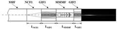
图1(b)是本发明提出的探头的结构示意图。SMF,单模光纤;NCF,无芯光纤;GIF1,一号梯度折射率光纤;SIMMF,阶跃折射率多模光纤;GIF2,二号梯度折射率光纤。Figure 1(b) is a schematic structural diagram of the probe proposed by the present invention. SMF, single-mode fiber; NCF, coreless fiber; GIF1, graded-index fiber No. 1; SIMMF, step-index multimode fiber; GIF2, graded-index fiber No. 2.
图2传统探头(Probe a)与本发明提出的探头(Probe b)模式能量分布情况,1-9分别表示LP0n(n=1,2,…9)等不同的模式。Fig. 2 mode energy distribution of the traditional probe (Probe a) and the probe (Probe b) proposed by the present invention, 1-9 respectively represent different modes such as LP0n (n=1, 2, . . . 9).
图3为传统探头的典型模拟结果。Figure 3 shows typical simulation results for a conventional probe.
图3(a)是传统探头输出光束二维强度分布图。Figure 3(a) is a two-dimensional intensity distribution diagram of the output beam of a conventional probe.
图3(b)是传统探头的轴上强度分布(与高斯光束情况对比)。Figure 3(b) is the on-axis intensity distribution of a conventional probe (compared to the Gaussian beam case).
图3(c)是传统探头输出光束直径随传输距离变化的关系(与高斯光束情况对比)。Figure 3(c) is the relationship between the diameter of the output beam of the conventional probe and the transmission distance (compared with the case of the Gaussian beam).
图3(d)是传统探头工作距离附近垂轴方向归一化强度分布情况(与高斯光束情况对比)。Figure 3(d) shows the normalized intensity distribution in the vertical axis direction near the working distance of the traditional probe (compared with the Gaussian beam).
图4为本发明的典型模拟结果。Figure 4 is a typical simulation result of the present invention.
图4(a)是本发明提出的探头输出光束二维强度分布图。Fig. 4(a) is a two-dimensional intensity distribution diagram of the output beam of the probe proposed by the present invention.
图4(b)是本发明提出的探头的轴上强度分布(与高斯光束情况对比)。Fig. 4(b) is the on-axis intensity distribution of the probe proposed by the present invention (compared with the case of Gaussian beam).
图4(c)是本发明提出的探头输出光束直径随传输距离变化的关系(与高斯光束情况对比)。Fig. 4(c) is the relationship between the diameter of the output beam of the probe proposed by the present invention and the transmission distance (compared with the case of the Gaussian beam).
图4(d)是本发明提出的探头工作距离附近垂轴方向归一化强度分布情况(与高斯光束情况对比)。Figure 4(d) is the normalized intensity distribution in the vertical axis direction near the working distance of the probe proposed by the present invention (compared with the Gaussian beam).
具体实施方式Detailed ways
下面结合附图和示例来详细说明本发明,但本发明不仅限于此。The present invention will be described in detail below with reference to the accompanying drawings and examples, but the present invention is not limited thereto.
激发更多的模式有利于获得更大的焦深拓展倍数。一种显而易见的技术方案是采用具有更大纤芯直径的SIMMF,利用高阶模式增加焦深的方案如图1(a)所示,该光纤探头由一段单模光纤(SMF)及一系列光纤段GIF-SIMMF-GIF2组成,其中GIF用于操控SIMMF中的激发模式,GIF2用于调控输出光束。由于更高阶的模场更接近贝塞尔场,为了进一步扩展焦深,需要激发更高阶的LP0n模式,因此,本发明通过将一段NCF1光纤插入到SMF和GIF1之间,如图1(b)所示。来自SMF的光束首先在NCF1中扩展,然后由GIF1聚焦。聚焦光束的发散角随着NCF1长度的增加而增加。通过确定GIF1的长度,使光束仅聚焦在GIF1和SIMMF的交界面上,使得光束在SIMMF内激发更高阶的模式。由图2可知,相较于现有方案,本发明提出的探头将能量耦合进了更高阶模式,模式数目更多。Exciting more modes is beneficial to obtain a larger magnification of the depth of focus. An obvious technical solution is to use a SIMMF with a larger core diameter to increase the depth of focus using higher-order modes, as shown in Figure 1(a). The fiber probe consists of a single-mode fiber (SMF) and a series of fibers. The segment GIF-SIMMF-GIF2 consists of GIF for manipulating the excitation mode in SIMMF and GIF2 for manipulating the output beam. Since the higher-order mode field is closer to the Bessel field, in order to further expand the depth of focus, the higher-order LP0n mode needs to be excited. Therefore, in the present invention, a section of NCF1 fiber is inserted between the SMF and GIF1, as shown in Figure 1 ( b) shown. The beam from SMF is first expanded in NCF1 and then focused by GIF1. The divergence angle of the focused beam increases with the length of NCF1. By determining the length of GIF1 so that the beam is focused only on the interface of GIF1 and SIMMF, the beam excites higher-order modes within SIMMF. It can be seen from FIG. 2 that, compared with the existing solution, the probe proposed by the present invention couples energy into higher-order modes, and the number of modes is larger.
对上述两种探头结构进行仿真,可得到不同方案下的系统结构参数及输出结果,进而比较两种方案的性能差异。设定输出光束在工作距离内平均光束直径为5μm左右,探头的模间色散小于2.5μm,模拟所用光纤参数如表1所示。By simulating the above two probe structures, the system structure parameters and output results under different schemes can be obtained, and then the performance differences of the two schemes can be compared. The average beam diameter of the output beam within the working distance is set to be about 5 μm, and the intermodal dispersion of the probe is less than 2.5 μm. The fiber parameters used for the simulation are shown in Table 1.
表1探头所使用的光纤参数Table 1 Optical fiber parameters used by the probe


对于上述现有的探头方案,经过仿真计算,可得到该结构的一组优化参数为:GIF的长度为160μm,SIMMF的长度为730μm,GIF2的长度为66.8μm,相较于高斯光束情况,对应焦深增益达到最大值3.4,对应工作距离比为1.4。其输出光束在空气中的强度分布如图3(a)所示,输出光束强度、光斑直径以及工作距离处垂轴方向能量分布如图3(b-d)所示。结果表明,该方案焦深范围为高斯光束的3.4倍,工作距离处旁瓣强度为主瓣强度的40-50%。For the above existing probe scheme, through simulation calculation, a set of optimized parameters for the structure can be obtained: the length of GIF is 160 μm, the length of SIMMF is 730 μm, and the length of GIF2 is 66.8 μm. Compared with the Gaussian beam, the corresponding The focal depth gain reaches a maximum value of 3.4, corresponding to a working distance ratio of 1.4. The intensity distribution of the output beam in the air is shown in Figure 3(a), and the output beam intensity, spot diameter and energy distribution along the vertical axis at the working distance are shown in Figure 3(b-d). The results show that the focal depth range of this scheme is 3.4 times that of the Gaussian beam, and the sidelobe intensity at the working distance is 40-50% of the mainlobe intensity.
由于随着高阶模式阶数的提高,模间最大群速度折射率之差会迅速提高,因此本发明提出的探头将模间色散约束在5-10μm。一组该方案优化的结构参数为:NCF1的长度为215μm,GIF1的长度为362.3μm,SIMMF的长度为470μm,GIF2的长度为497.6μm,相较于高斯光束的情况,对应焦深扩展倍数为3.8,工作距离比为2.1。输出光束强度、直径等信息如图4(a-d)所示。仿真结果表明,本发明提出的方案输出光束轴上光强均匀性较好,光束直径随传输距离的增加变化得更为缓慢,工作距离附近旁瓣强度仅为主瓣强度的30%左右。通过与传统探头的结果对比可知,本发明的探头在焦深优化及旁瓣抑制方面优于上述现有方案的探头。Since the maximum group velocity refractive index difference between modes increases rapidly with the increase of the order of higher-order modes, the probe proposed in the present invention constrains the inter-mode dispersion to 5-10 μm. A set of structural parameters optimized by this scheme are: the length of NCF1 is 215 μm, the length of GIF1 is 362.3 μm, the length of SIMMF is 470 μm, and the length of GIF2 is 497.6 μm. Compared with the case of Gaussian beam, the corresponding focal depth expansion factor is 3.8, and the working distance ratio is 2.1. The output beam intensity, diameter and other information are shown in Fig. 4(a-d). The simulation results show that the proposed scheme has good uniformity of light intensity on the output beam axis, the beam diameter changes more slowly with the increase of transmission distance, and the side lobe intensity near the working distance is only about 30% of the main lobe intensity. It can be seen from the comparison with the results of the traditional probe that the probe of the present invention is superior to the probe of the above-mentioned existing solution in terms of focal depth optimization and side lobe suppression.
本发明提出的一种新的光纤探头结构,通过激发更高阶模式的光束实现焦深扩展和旁瓣抑制,适用于OCT。通过仿真与传统多模探头进行对比,可知本发明所提出的探头具有更长的焦深和更弱的旁瓣效应,整体结构简单、易于制造,应用场景灵活,因此在重要领域中具有较大应用潜力。A novel optical fiber probe structure proposed by the present invention realizes focal depth expansion and side lobe suppression by exciting a higher-order mode beam, and is suitable for OCT. By comparing the simulation with the traditional multimode probe, it can be seen that the probe proposed by the present invention has a longer focal depth and weaker side lobe effect, has a simple overall structure, is easy to manufacture, and has flexible application scenarios. application potential.
Claims (1)
Translated fromChinesePriority Applications (1)
| Application Number | Priority Date | Filing Date | Title |
|---|---|---|---|
| CN202110013245.8ACN112842270B (en) | 2021-01-06 | 2021-01-06 | A focal depth extension probe based on high-order mode energy control |
Applications Claiming Priority (1)
| Application Number | Priority Date | Filing Date | Title |
|---|---|---|---|
| CN202110013245.8ACN112842270B (en) | 2021-01-06 | 2021-01-06 | A focal depth extension probe based on high-order mode energy control |
Publications (2)
| Publication Number | Publication Date |
|---|---|
| CN112842270A CN112842270A (en) | 2021-05-28 |
| CN112842270Btrue CN112842270B (en) | 2022-05-17 |
Family
ID=76004192
Family Applications (1)
| Application Number | Title | Priority Date | Filing Date |
|---|---|---|---|
| CN202110013245.8AActiveCN112842270B (en) | 2021-01-06 | 2021-01-06 | A focal depth extension probe based on high-order mode energy control |
Country Status (1)
| Country | Link |
|---|---|
| CN (1) | CN112842270B (en) |
Citations (7)
| Publication number | Priority date | Publication date | Assignee | Title |
|---|---|---|---|---|
| JP2015006326A (en)* | 2013-05-29 | 2015-01-15 | 住友電気工業株式会社 | Method for manufacturing catheter for optical coherence tomography apparatus, and catheter for optical coherence tomography apparatus |
| CN105103019A (en)* | 2013-02-01 | 2015-11-25 | 波利瓦勒有限合伙公司 | Asymmetric optical fiber coupler |
| CN105193379A (en)* | 2015-07-31 | 2015-12-30 | 浙江大学 | All-fiber endoscopic OCT probe based on tapered structure |
| CN107515446A (en)* | 2017-09-14 | 2017-12-26 | 浙江大学 | Method and Probe for Expanding Focal Depth Based on Fiber-type Pupil Filter |
| CN207366785U (en)* | 2017-09-14 | 2018-05-15 | 浙江大学 | Probe based on optical-fiber type iris filter extended focal depth |
| EP3378430A1 (en)* | 2013-10-15 | 2018-09-26 | Nipro Corporation | Ablation system and ablation device |
| CN110764248A (en)* | 2019-09-26 | 2020-02-07 | 浙江大学 | Probe with optimized focal depth, working distance and axial light intensity uniformity |
Family Cites Families (7)
| Publication number | Priority date | Publication date | Assignee | Title |
|---|---|---|---|---|
| US6891984B2 (en)* | 2002-07-25 | 2005-05-10 | Lightlab Imaging, Llc | Scanning miniature optical probes with optical distortion correction and rotational control |
| CN102499619A (en)* | 2011-10-13 | 2012-06-20 | 上海大学 | GRIN (Gradient-Index Fiber Probe) optical fiber probe and manufacturing method, focusing performance detection device and detection method thereof |
| CN202489922U (en)* | 2012-01-18 | 2012-10-17 | 广州宝胆医疗器械科技有限公司 | Capsule enteroscopy system with optical coherence tomography function |
| US8964806B2 (en)* | 2012-01-19 | 2015-02-24 | Insight Photonic Solutions, Inc. | System and method for generating an optimum side-mode suppression ratio continuous tuning path for a semiconductor tunable laser |
| CN103211567B (en)* | 2013-05-07 | 2015-02-11 | 深圳市中科微光医疗器械技术有限公司 | Integrated super-miniature optical coherence tomography probe |
| KR20150035320A (en)* | 2013-09-27 | 2015-04-06 | 삼성전자주식회사 | Varifocal lens, optical scanning probe including the same, and medical apparatus employing the optical scanning probe |
| CN106691373A (en)* | 2016-09-28 | 2017-05-24 | 天津恒宇医疗科技有限公司 | OCT (optical coherence tomography) probe for small cavity and blood vessel endoscope imaging |
- 2021
- 2021-01-06CNCN202110013245.8Apatent/CN112842270B/enactiveActive
Patent Citations (8)
| Publication number | Priority date | Publication date | Assignee | Title |
|---|---|---|---|---|
| CN105103019A (en)* | 2013-02-01 | 2015-11-25 | 波利瓦勒有限合伙公司 | Asymmetric optical fiber coupler |
| JP2015006326A (en)* | 2013-05-29 | 2015-01-15 | 住友電気工業株式会社 | Method for manufacturing catheter for optical coherence tomography apparatus, and catheter for optical coherence tomography apparatus |
| EP3378430A1 (en)* | 2013-10-15 | 2018-09-26 | Nipro Corporation | Ablation system and ablation device |
| CN105193379A (en)* | 2015-07-31 | 2015-12-30 | 浙江大学 | All-fiber endoscopic OCT probe based on tapered structure |
| CN106913309A (en)* | 2015-07-31 | 2017-07-04 | 浙江大学 | All -fiber endoscopic OCT probe based on unit wimble structure |
| CN107515446A (en)* | 2017-09-14 | 2017-12-26 | 浙江大学 | Method and Probe for Expanding Focal Depth Based on Fiber-type Pupil Filter |
| CN207366785U (en)* | 2017-09-14 | 2018-05-15 | 浙江大学 | Probe based on optical-fiber type iris filter extended focal depth |
| CN110764248A (en)* | 2019-09-26 | 2020-02-07 | 浙江大学 | Probe with optimized focal depth, working distance and axial light intensity uniformity |
Non-Patent Citations (3)
| Title |
|---|
| OCT光纤探头的研制与成像应用;邱建榕;《中国博士学位论文全文数据库》;20201231;第1-80页* |
| Ultrathin lensed fiber-optic probe for optical coherence tomography;Qiu, Y;《BIOMEDICAL OPTICS EXPRESS 》;20161231;第1-3页* |
| 侧视型内窥OCT光纤探头研究;潘瑞斌;《中国博士学位论文全文数据库》;20201231;第1-69页* |
Also Published As
| Publication number | Publication date |
|---|---|
| CN112842270A (en) | 2021-05-28 |
Similar Documents
| Publication | Publication Date | Title |
|---|---|---|
| JP6804636B2 (en) | Optical imaging system using vortex fibers for multimode lighting | |
| CN107515446B (en) | Method and probe for extending focal depth based on fiber-type pupil filter | |
| Lorenser et al. | Ultrathin fiber probes with extended depth of focus<? A3B2 show [pmg: line-break justify=" yes"/]?> for optical coherence tomography | |
| Tan et al. | In-fiber common-path optical coherence tomography using a conical-tip fiber | |
| Mao et al. | Graded-index fiber lens proposed for ultrasmall probes used in biomedical imaging | |
| Yablon et al. | Low-loss high-strength microstructured fiber fusion splices using GRIN fiber lenses | |
| JP6549106B2 (en) | Optical scanner and scan lens optical probe | |
| CN108873171B (en) | A multi-core fiber-like Bessel beam array optical tweezers | |
| US20220082368A1 (en) | Probe with optimized focal depth, working distance and axial light intensity uniformity | |
| CN109752830B (en) | An all-fiber STED super-resolution microscope illumination device | |
| JP2006512616A (en) | Optical fiber lens and manufacturing method | |
| CN111653378B (en) | STED super-resolution microscopic imaging device based on multi-fiber optical tweezers | |
| Lee et al. | Ultra-thin and flexible endoscopy probe for optical coherence tomography based on stepwise transitional core fiber | |
| CN103996423A (en) | Single-optical-fiber optical tweezers adjustable in transverse capture position | |
| CN119395875A (en) | An all-fiber beam modulation and collection system based on double superlenses and its design method | |
| CN105241842A (en) | Small optical fiber refractive index sensor based on single mode-multimode-single mode optical fiber taper head (SMST) | |
| CN116774426A (en) | Pupil mask for generating quasi-diffraction-free light sheet and optimal design method thereof | |
| Moon et al. | Lens-free endoscopy probe for optical coherence tomography | |
| Wang et al. | Two-photon endomicroscopy with microsphere-spliced double-cladding antiresonant fiber for resolution enhancement | |
| CN112842270B (en) | A focal depth extension probe based on high-order mode energy control | |
| Thomas et al. | Metaoptics for aberration correction in microendoscopy | |
| CN207366785U (en) | Probe based on optical-fiber type iris filter extended focal depth | |
| Duan et al. | Probe alignment and design issues of microelectromechanical system based optical coherence tomography endoscopic imaging | |
| Lee et al. | Common-path all-fiber optical coherence tomography probe based on high-index elliptical epoxy-lensed fiber | |
| Wang et al. | Measurement of the focusing constant of gradient-index fiber lens and its application in developing GRIN fiber probes |
Legal Events
| Date | Code | Title | Description |
|---|---|---|---|
| PB01 | Publication | ||
| PB01 | Publication | ||
| SE01 | Entry into force of request for substantive examination | ||
| SE01 | Entry into force of request for substantive examination | ||
| GR01 | Patent grant | ||
| GR01 | Patent grant |