CN112839472B - Interval heat dissipation formula regulator cubicle - Google Patents
Interval heat dissipation formula regulator cubicleDownload PDFInfo
- Publication number
- CN112839472B CN112839472BCN202011608320.7ACN202011608320ACN112839472BCN 112839472 BCN112839472 BCN 112839472BCN 202011608320 ACN202011608320 ACN 202011608320ACN 112839472 BCN112839472 BCN 112839472B
- Authority
- CN
- China
- Prior art keywords
- heat
- vertical
- cabinet
- frame
- mounting frame
- Prior art date
- Legal status (The legal status is an assumption and is not a legal conclusion. Google has not performed a legal analysis and makes no representation as to the accuracy of the status listed.)
- Active
Links
Images


Classifications
- H—ELECTRICITY
- H05—ELECTRIC TECHNIQUES NOT OTHERWISE PROVIDED FOR
- H05K—PRINTED CIRCUITS; CASINGS OR CONSTRUCTIONAL DETAILS OF ELECTRIC APPARATUS; MANUFACTURE OF ASSEMBLAGES OF ELECTRICAL COMPONENTS
- H05K7/00—Constructional details common to different types of electric apparatus
- H05K7/14—Mounting supporting structure in casing or on frame or rack
- H—ELECTRICITY
- H05—ELECTRIC TECHNIQUES NOT OTHERWISE PROVIDED FOR
- H05K—PRINTED CIRCUITS; CASINGS OR CONSTRUCTIONAL DETAILS OF ELECTRIC APPARATUS; MANUFACTURE OF ASSEMBLAGES OF ELECTRICAL COMPONENTS
- H05K7/00—Constructional details common to different types of electric apparatus
- H05K7/20—Modifications to facilitate cooling, ventilating, or heating
- H05K7/20009—Modifications to facilitate cooling, ventilating, or heating using a gaseous coolant in electronic enclosures
- H05K7/20136—Forced ventilation, e.g. by fans
- H05K7/20172—Fan mounting or fan specifications
- H—ELECTRICITY
- H05—ELECTRIC TECHNIQUES NOT OTHERWISE PROVIDED FOR
- H05K—PRINTED CIRCUITS; CASINGS OR CONSTRUCTIONAL DETAILS OF ELECTRIC APPARATUS; MANUFACTURE OF ASSEMBLAGES OF ELECTRICAL COMPONENTS
- H05K7/00—Constructional details common to different types of electric apparatus
- H05K7/20—Modifications to facilitate cooling, ventilating, or heating
- H05K7/2039—Modifications to facilitate cooling, ventilating, or heating characterised by the heat transfer by conduction from the heat generating element to a dissipating body
- H05K7/20409—Outer radiating structures on heat dissipating housings, e.g. fins integrated with the housing
- H05K7/20418—Outer radiating structures on heat dissipating housings, e.g. fins integrated with the housing the radiating structures being additional and fastened onto the housing
- Y—GENERAL TAGGING OF NEW TECHNOLOGICAL DEVELOPMENTS; GENERAL TAGGING OF CROSS-SECTIONAL TECHNOLOGIES SPANNING OVER SEVERAL SECTIONS OF THE IPC; TECHNICAL SUBJECTS COVERED BY FORMER USPC CROSS-REFERENCE ART COLLECTIONS [XRACs] AND DIGESTS
- Y02—TECHNOLOGIES OR APPLICATIONS FOR MITIGATION OR ADAPTATION AGAINST CLIMATE CHANGE
- Y02D—CLIMATE CHANGE MITIGATION TECHNOLOGIES IN INFORMATION AND COMMUNICATION TECHNOLOGIES [ICT], I.E. INFORMATION AND COMMUNICATION TECHNOLOGIES AIMING AT THE REDUCTION OF THEIR OWN ENERGY USE
- Y02D10/00—Energy efficient computing, e.g. low power processors, power management or thermal management
Landscapes
- Engineering & Computer Science (AREA)
- Microelectronics & Electronic Packaging (AREA)
- Physics & Mathematics (AREA)
- Thermal Sciences (AREA)
- Cooling Or The Like Of Electrical Apparatus (AREA)
Abstract
Translated fromChinese
Description
Translated fromChinese技术领域technical field
本说明书一个或多个实施例涉及电气柜技术领域,尤其涉及一种间隔散热式电气柜。One or more embodiments of this specification relate to the technical field of electric cabinets, and in particular, to a partitioned heat dissipation electric cabinet.
背景技术Background technique
电气柜是由钢材质加工而成用来保护元器件正常工作的柜子,电气柜制作材料一般分为热轧钢板和冷轧钢板两种,冷轧钢板相对热轧钢板更材质柔软,更适合电气柜的制作,电气柜用途广泛主要用于化工行业,环保行业,电力系统,冶金系统,工业,核电行业,消防安全监控,交通行业等等。The electrical cabinet is made of steel to protect the normal operation of the components. The materials for the electrical cabinet are generally divided into two types: hot-rolled steel plate and cold-rolled steel plate. Compared with hot-rolled steel plate, cold-rolled steel plate is softer and more suitable for electrical appliances. The production of cabinets, electrical cabinets are widely used mainly in chemical industry, environmental protection industry, power system, metallurgical system, industry, nuclear power industry, fire safety monitoring, transportation industry and so on.
本申请人发现在目前的电气柜往往采用内外空气交换以带走内部电气器件产生的热量,以进行散热,而内外空气直接流通容易导致外界的水汽灰尘等进入电气柜内部,容易导致内部电气器件损坏,并且电气柜内部的散热机构往往为固定结构,总体散热的效率一定,难以根据具体电气器件安装数量位置和所需的散热功率以灵活调节其具体散热结构,使用灵活性较低。The applicant found that the current electrical cabinets often use internal and external air exchange to take away the heat generated by the internal electrical components for heat dissipation, and the direct circulation of internal and external air may easily cause external water vapor and dust to enter the electrical cabinet, which may easily lead to internal electrical components. Damage, and the heat dissipation mechanism inside the electrical cabinet is often a fixed structure, the overall heat dissipation efficiency is certain, it is difficult to flexibly adjust the specific heat dissipation structure according to the specific installation quantity and position of the specific electrical components and the required heat dissipation power, and the use flexibility is low.
发明内容Contents of the invention
有鉴于此,本说明书一个或多个实施例的目的在于提出一种间隔散热式电气柜,以解决的问题。In view of this, the purpose of one or more embodiments of this specification is to propose a partitioned heat dissipation electrical cabinet to solve the problem.
基于上述目的,本说明书一个或多个实施例提供了一种间隔散热式电气柜,包括:Based on the above purpose, one or more embodiments of this specification provide a partitioned heat dissipation electrical cabinet, including:
柜体,所述柜体的正面设置有柜门,所述柜体的左右两侧均设置有侧挡板,所述侧挡板的中间设置有中空夹层,所述侧挡板的内侧上方设置有上侧开口,所述侧挡板的内侧下方设置有下侧开口;Cabinet body, the front of the cabinet body is provided with a cabinet door, the left and right sides of the cabinet body are provided with side baffles, the middle of the side baffles is provided with a hollow interlayer, and the inner side and upper side of the side baffles are arranged There is an upper side opening, and a lower side opening is arranged under the inner side of the side baffle;
悬吊安装架,设置于所述侧挡板的内侧面,所述悬吊安装架的外侧设置有橡胶连接块,所述悬吊安装架的中间设置有连接卡槽;The suspension mounting frame is arranged on the inner surface of the side baffle, the outer side of the suspension mounting frame is provided with a rubber connection block, and the middle of the suspension mounting frame is provided with a connecting card slot;
器件安装框架,设置于所述柜体的内部中间,所述器件安装框架的左右两侧均设置有竖向安装架,所述竖向安装架的中间设置有安装螺孔,所述器件安装框架的外侧设置有悬吊卡块;The device installation frame is arranged in the middle of the interior of the cabinet, the left and right sides of the device installation frame are provided with vertical installation frames, the middle of the vertical installation frame is provided with mounting screw holes, and the device installation frame Suspension blocks are provided on the outside;
导向安装架,设置于所述竖向安装架的内侧,所述导向安装架的内侧设置有导向滑轨,所述导向安装架的中间设置有连接螺孔,所述导向安装架的前端设置有水平锁定套筒,所述水平锁定套筒的内侧嵌合设置有锁定卡笋,所述锁定卡笋的后侧设置有锁定弹簧,所述锁定卡笋的前端设置有导向斜面,所述锁定卡笋的中间设置有解锁拨钮;The guide mounting frame is arranged on the inner side of the vertical mounting frame, the guide slide rail is arranged on the inside of the guide mounting frame, the connecting screw hole is arranged in the middle of the guiding mounting frame, and the front end of the guiding mounting frame is provided with A horizontal locking sleeve, the inner side of the horizontal locking sleeve is fitted with a locking latch, the rear side of the locking latch is provided with a locking spring, the front end of the locking latch is provided with a guide slope, and the locking latch There is an unlock button in the middle of the bamboo shoots;
单元散热架,设置于所述导向滑轨的内侧,所述单元散热架的前端设置有锁定卡槽,所述单元散热架的中间设置有导向滑槽,所述单元散热架的内侧平行设置有多个吸热鳍片,所述吸热鳍片的中间设置有导热管,所述导热管的后端设置有导热接触板,所述导热接触板的后侧面均匀设置有嵌合凸块;The unit cooling frame is arranged on the inner side of the guide slide rail, the front end of the unit cooling frame is provided with a locking slot, the middle of the unit cooling frame is provided with a guide chute, and the inner side of the unit cooling frame is arranged in parallel. A plurality of heat-absorbing fins, a heat-conducting pipe is arranged in the middle of the heat-absorbing fin, a heat-conducting contact plate is provided at the rear end of the heat-conducting pipe, and a fitting protrusion is evenly provided on the rear side of the heat-conducting contact plate;
竖向导热板,设置于所述柜体的内部后侧,所述竖向导热板的正面均匀设置有嵌合凹槽,所述竖向导热板的中间设置有散热连接管,所述散热连接管的外端平行设置有多个散热鳍片,所述散热鳍片的外侧设置有散热风扇;The vertical heat conduction plate is arranged on the inner rear side of the cabinet, and the front of the vertical heat conduction plate is evenly provided with fitting grooves, and the middle of the vertical heat conduction plate is provided with a heat dissipation connecting pipe, and the heat dissipation connection The outer end of the tube is provided with a plurality of cooling fins in parallel, and the outer side of the cooling fins is provided with a cooling fan;
所述上侧开口内侧靠近侧挡板水平中心线的一侧和所述下侧开口内侧靠近侧挡板水平中心线的一侧均设置有流通风扇,所述流通风扇的竖直中心线与所述柜体的竖直中心线之间相互垂直。The inner side of the upper opening near the horizontal centerline of the side baffle and the side of the lower opening near the horizontal centerline of the side baffle are provided with circulation fans, and the vertical centerline of the circulation fan is in line with the horizontal centerline of the side baffle. The vertical centerlines of the cabinets are perpendicular to each other.
在一些可选实施例中,所述悬吊安装架通过所述橡胶连接块与所述侧挡板相连接,所述器件安装框架通过所述悬吊卡块和所述连接卡槽与所述悬吊安装架相连接,所述悬吊卡块与所述连接卡槽之间尺寸相互配合。In some optional embodiments, the suspension installation frame is connected to the side fence through the rubber connection block, and the device installation frame is connected to the side panel through the suspension block and the connection slot. The suspension mounting brackets are connected, and the dimensions of the suspension block and the connection slot match each other.
在一些可选实施例中,所述竖向安装架的中间均匀间隔设置有多个安装螺孔,所述竖向安装架的竖直中心线与所述柜体的竖直中心线之间相互垂直。In some optional embodiments, a plurality of mounting screw holes are evenly spaced in the middle of the vertical installation frame, and the vertical centerline of the vertical installation frame and the vertical centerline of the cabinet body are mutually connected. vertical.
在一些可选实施例中,所述单元散热架通过所述导向滑槽与所述导向滑轨滑动连接,所述导向滑轨的水平中心线与所述柜体的竖直中心线之间相互垂直。In some optional embodiments, the unit cooling rack is slidably connected to the guide rail through the guide chute, and the horizontal centerline of the guide rail and the vertical centerline of the cabinet body are mutually connected. vertical.
在一些可选实施例中,所述吸热鳍片通过所述导热管与所述导热接触板相连接,所述吸热鳍片的外侧面与所述柜体的竖直中心线之间相互平行。In some optional embodiments, the heat-absorbing fins are connected to the heat-conducting contact plate through the heat-conducting pipes, and the outer surface of the heat-absorbing fins and the vertical centerline of the cabinet body are connected to each other. parallel.
在一些可选实施例中,所述锁定卡槽与所述锁定卡笋之间尺寸相互配合。In some optional embodiments, the dimensions of the locking slot and the locking shoot match each other.
在一些可选实施例中,所述导热接触板通过所述嵌合凸块和所述嵌合凹槽与所述竖向导热板相互贴合连接,所述嵌合凸块和所述嵌合凹槽之间尺寸相互配合。In some optional embodiments, the thermal conduction contact plate is fitted and connected to the vertical heat conducting plate through the fitting protrusion and the fitting groove, and the fitting protrusion and the fitting The dimensions of the grooves match each other.
在一些可选实施例中,所述嵌合凹槽的竖直中心线与所述柜体的竖直中心线之间相互平行。In some optional embodiments, the vertical centerline of the fitting groove and the vertical centerline of the cabinet body are parallel to each other.
在一些可选实施例中,所述散热鳍片位于所述柜体的后侧,所述散热鳍片与所述竖向导热板之间通过所述散热连接管进行连接。In some optional embodiments, the heat dissipation fins are located at the rear side of the cabinet, and the heat dissipation fins are connected to the vertical heat conducting plates through the heat dissipation connecting pipes.
从上面所述可以看出,本说明书一个或多个实施例提供的间隔散热式电气柜,通过柜体内部设置的器件安装框架可以安装相应的电气器件,而器件安装框架整体通过悬吊安装架悬挂在柜体的侧挡板上,通过橡胶连接块进行间隔连接,以为器件安装框架整体提供减震,避免外部震动直接传递到器件安装框架上安装的电气器件上,提高电气柜整体的可靠性,而柜体内部还设置有一个整体的竖向导热板,竖向导热板可以吸收柜体内部热量,并通过散热连接管将热量传递到柜体外部进行散热,同时电气柜设置有多个单元散热架,每个单元散热架都可以快速安装到器件安装框架上,并与竖向导热板相互贴附,从而提高竖向导热板整体的吸热效率,进而提高电气柜整体的散热效率,同时便于根据内部器件安装需求调节单元散热架的位置和数量,使用更加方便灵活。From the above, it can be seen that in the partitioned heat dissipation electrical cabinet provided by one or more embodiments of this specification, the corresponding electrical devices can be installed through the device installation frame installed inside the cabinet, and the device installation frame as a whole can be installed through the suspension installation frame. Suspended on the side baffle of the cabinet body, and connected at intervals through rubber connecting blocks, to provide shock absorption for the device installation frame as a whole, to prevent external vibration from being directly transmitted to the electrical devices installed on the device installation frame, and to improve the overall reliability of the electrical cabinet , and there is an integral vertical heat conduction plate inside the cabinet, the vertical heat conduction plate can absorb the heat inside the cabinet, and transfer the heat to the outside of the cabinet through the heat dissipation connecting pipe for heat dissipation, and the electrical cabinet is equipped with multiple units Heat dissipation frame, each unit heat dissipation frame can be quickly installed on the device installation frame, and attached to each other with the vertical heat conduction plate, thereby improving the overall heat absorption efficiency of the vertical heat conduction plate, thereby improving the overall heat dissipation efficiency of the electrical cabinet, and at the same time It is convenient to adjust the position and quantity of the cooling rack of the unit according to the installation requirements of the internal components, and it is more convenient and flexible to use.
附图说明Description of drawings
为了更清楚地说明本说明书一个或多个实施例或现有技术中的技术方案,下面将对实施例或现有技术描述中所需要使用的附图作简单地介绍,显而易见地,下面描述中的附图仅仅是本说明书一个或多个实施例,对于本领域普通技术人员来讲,在不付出创造性劳动的前提下,还可以根据这些附图获得其他的附图。In order to more clearly illustrate one or more embodiments of this specification or the technical solutions in the prior art, the following will briefly introduce the drawings that need to be used in the description of the embodiments or prior art. Obviously, in the following description The accompanying drawings are only one or more embodiments of this specification, and those of ordinary skill in the art can also obtain other drawings according to these drawings without creative work.
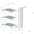
图1为本说明书一个或多个实施例的内部结构示意图;Figure 1 is a schematic diagram of the internal structure of one or more embodiments of this specification;
图2为本说明书一个或多个实施例的正面结构示意图;Fig. 2 is a schematic diagram of the front structure of one or more embodiments of this specification;
图3为本说明书一个或多个实施例的背面结构示意图;Fig. 3 is a schematic diagram of the rear structure of one or more embodiments of this specification;
图4为本说明书一个或多个实施例的纵向剖面结构示意图;Fig. 4 is a schematic longitudinal sectional structure diagram of one or more embodiments of the present specification;
图5为本说明书一个或多个实施例的分解结构示意图;Fig. 5 is a schematic diagram of an exploded structure of one or more embodiments of the present specification;
图6为本说明书一个或多个实施例的侧挡板的结构示意图;Fig. 6 is a schematic structural view of side baffles in one or more embodiments of the present specification;
图7为本说明书一个或多个实施例的器件安装框架的结构示意图;FIG. 7 is a schematic structural diagram of a device mounting frame according to one or more embodiments of the present specification;
图8为本说明书一个或多个实施例的导向安装架的结构示意图;Fig. 8 is a schematic structural diagram of a guide installation frame according to one or more embodiments of the present specification;
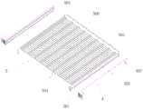
图9为本说明书一个或多个实施例的单元散热架的结构示意图;FIG. 9 is a schematic structural diagram of a unit cooling rack in one or more embodiments of the present specification;
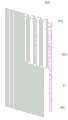
图10为本说明书一个或多个实施例的竖向导热板的结构示意图;Fig. 10 is a schematic structural diagram of a vertical heat conducting plate according to one or more embodiments of the present specification;
图中:1柜体、101柜门、102侧挡板、103中空夹层、104上侧开口、105下侧开口、106流通风扇、2悬吊安装架、201橡胶连接块、202连接卡槽、3器件安装框架、301竖向安装架、302安装螺孔、303悬吊卡块、4导向安装架、401导向滑轨、402连接螺孔、403水平锁定套筒、404锁定卡笋、405锁定弹簧、406导向斜面、407解锁拨钮、5单元散热架、501锁定卡槽、502导向滑槽、503吸热鳍片、504导热管、505导热接触板、506嵌合凸块、6竖向导热板、601嵌合凹槽、602散热连接管、603散热鳍片、604散热风扇。In the figure: 1 cabinet body, 101 cabinet door, 102 side baffle, 103 hollow interlayer, 104 upper opening, 105 lower opening, 106 circulation fan, 2 suspension mounting frame, 201 rubber connection block, 202 connection card slot, 3 device mounting frame, 301 vertical mounting frame, 302 mounting screw hole, 303 suspension block, 4 guiding mounting frame, 401 guiding slide rail, 402 connecting screw hole, 403 horizontal locking sleeve, 404 locking card shoot, 405 locking Spring, 406 guiding slope, 407 unlocking dial, 5 unit heat sink, 501 locking card slot, 502 guiding chute, 503 heat absorbing fin, 504 heat pipe, 505 heat conducting contact plate, 506 fitting bump, 6 vertical guide Hot plate, 601 fitting groove, 602 heat dissipation connecting pipe, 603 heat dissipation fin, 604 heat dissipation fan.
具体实施方式Detailed ways
为使本公开的目的、技术方案和优点更加清楚明白,以下结合具体实施例,对本公开进一步详细说明。In order to make the purpose, technical solutions and advantages of the present disclosure clearer, the present disclosure will be further described in detail below in conjunction with specific embodiments.
需要说明的是,除非另外定义,本说明书一个或多个实施例使用的技术术语或者科学术语应当为本公开所属领域内具有一般技能的人士所理解的通常意义。本说明书一个或多个实施例中使用的“第一”、“第二”以及类似的词语并不表示任何顺序、数量或者重要性,而只是用来区分不同的组成部分。“包括”或者“包含”等类似的词语意指出现该词前面的元件或者物件涵盖出现在该词后面列举的元件或者物件及其等同,而不排除其他元件或者物件。“连接”或者“相连”等类似的词语并非限定于物理的或者机械的连接,而是可以包括电性的连接,不管是直接的还是间接的。“上”、“下”、“左”、“右”等仅用于表示相对位置关系,当被描述对象的绝对位置改变后,则该相对位置关系也可能相应地改变。It should be noted that, unless otherwise defined, the technical terms or scientific terms used in one or more embodiments of the present specification shall have ordinary meanings understood by those skilled in the art to which the present disclosure belongs. "First", "second" and similar words used in one or more embodiments of the present specification do not indicate any order, quantity or importance, but are only used to distinguish different components. "Comprising" or "comprising" and similar words mean that the elements or items appearing before the word include the elements or items listed after the word and their equivalents, without excluding other elements or items. Words such as "connected" or "connected" are not limited to physical or mechanical connections, but may include electrical connections, whether direct or indirect. "Up", "Down", "Left", "Right" and so on are only used to indicate the relative positional relationship. When the absolute position of the described object changes, the relative positional relationship may also change accordingly.
本说明书一个或多个实施例,一种间隔散热式电气柜,包括:One or more embodiments of this specification, a partition heat dissipation electrical cabinet, comprising:
柜体1,柜体1的正面设置有柜门101,柜体1的左右两侧均设置有侧挡板102,侧挡板102的中间设置有中空夹层103,侧挡板102的内侧上方设置有上侧开口104,侧挡板102的内侧下方设置有下侧开口105;
悬吊安装架2,设置于侧挡板102的内侧面,悬吊安装架2的外侧设置有橡胶连接块201,悬吊安装架2的中间设置有连接卡槽202;The
器件安装框架3,设置于柜体1的内部中间,器件安装框架3的左右两侧均设置有竖向安装架301,竖向安装架301的中间设置有安装螺孔302,器件安装框架3的外侧设置有悬吊卡块303;The
导向安装架4,设置于竖向安装架301的内侧,导向安装架4的内侧设置有导向滑轨401,导向安装架4的中间设置有连接螺孔402,导向安装架4的前端设置有水平锁定套筒403,水平锁定套筒403的内侧嵌合设置有锁定卡笋404,锁定卡笋404的后侧设置有锁定弹簧405,锁定卡笋404的前端设置有导向斜面406,锁定卡笋404的中间设置有解锁拨钮407;The
单元散热架5,设置于导向滑轨401的内侧,单元散热架5的前端设置有锁定卡槽501,单元散热架5的中间设置有导向滑槽502,单元散热架5的内侧平行设置有多个吸热鳍片503,吸热鳍片503的中间设置有导热管504,导热管504的后端设置有导热接触板505,导热接触板505的后侧面均匀设置有嵌合凸块506;The
竖向导热板6,设置于柜体1的内部后侧,竖向导热板6的正面均匀设置有嵌合凹槽601,竖向导热板6的中间设置有散热连接管602,散热连接管602的外端平行设置有多个散热鳍片603,散热鳍片603的外侧设置有散热风扇604。The vertical
请参阅图1至图10,作为本发明的一个实施例,一种间隔散热式电气柜,包括:柜体1,柜体1的正面设置有柜门101,柜体1的左右两侧均设置有侧挡板102,侧挡板102的中间设置有中空夹层103,侧挡板102的内侧上方设置有上侧开口104,侧挡板102的内侧下方设置有下侧开口105;悬吊安装架2,设置于侧挡板102的内侧面,悬吊安装架2的外侧设置有橡胶连接块201,悬吊安装架2的中间设置有连接卡槽202;器件安装框架3,设置于柜体1的内部中间,器件安装框架3的左右两侧均设置有竖向安装架301,竖向安装架301的中间设置有安装螺孔302,器件安装框架3的外侧设置有悬吊卡块303;导向安装架4,设置于竖向安装架301的内侧,导向安装架4的内侧设置有导向滑轨401,导向安装架4的中间设置有连接螺孔402,导向安装架4的前端设置有水平锁定套筒403,水平锁定套筒403的内侧嵌合设置有锁定卡笋404,锁定卡笋404的后侧设置有锁定弹簧405,锁定卡笋404的前端设置有导向斜面406,锁定卡笋404的中间设置有解锁拨钮407;单元散热架5,设置于导向滑轨401的内侧,单元散热架5的前端设置有锁定卡槽501,单元散热架5的中间设置有导向滑槽502,单元散热架5的内侧平行设置有多个吸热鳍片503,吸热鳍片503的中间设置有导热管504,导热管504的后端设置有导热接触板505,导热接触板505的后侧面均匀设置有嵌合凸块506;竖向导热板6,设置于柜体1的内部后侧,竖向导热板6的正面均匀设置有嵌合凹槽601,竖向导热板6的中间设置有散热连接管602,散热连接管602的外端平行设置有多个散热鳍片603,散热鳍片603的外侧设置有散热风扇604。Please refer to Fig. 1 to Fig. 10, as an embodiment of the present invention, a kind of interval cooling type electric cabinet comprises:
请参阅图2至图8,可选的,电气柜的柜体1正面设置有柜门101,用以开启柜体1,而柜体1内部空间则用以安装相应的电气器件,柜体1左右两侧设置有侧挡板102,而侧挡板102中间设置有中空夹层103,中空夹层103可以作为隔热保温层,提高侧挡板102的隔热效率,进而提高柜体1整体的隔热保温效率,避免外界温度对柜体1内部造成影响,提高柜体1内部环境的稳定性,以保护其内部安装的电气器件,同时侧挡板102的内侧设置有上侧开口104和下侧开口105,上侧开口104和下侧开口105通过中空夹层103连通,以构成一条空气流通风道,并且上侧开口104内侧靠近侧挡板102水平中心线的一侧和下侧开口105内侧靠近侧挡板102水平中心线的一侧均设置有流通风扇106,流通风扇106的竖直中心线与柜体1的竖直中心线之间相互垂直,而上下两个流通风扇106的风向同向,从而两个流通风扇106可以通过柜体1内部空间和中空夹层103使柜体1内部的空气竖向循环流通,以配合其中的散热机构提高扇热效率。Please refer to Fig. 2 to Fig. 8, optional, the
请参阅图2至图8,可选的,在一些可选实施例中,电气柜通过柜体1容纳相应的电气器件,而柜体1内部安装有器件安装框架3,竖向安装架301的中间均匀间隔设置有多个安装螺孔302,竖向安装架301的竖直中心线与柜体1的竖直中心线之间相互垂直,所以相应的电气器件均可以通过竖向安装架301上设置的安装螺孔302横向平行安装在器件安装框架3上,而悬吊安装架2通过橡胶连接块201与侧挡板102相连接,器件安装框架3通过悬吊卡块303和连接卡槽202与悬吊安装架2相连接,从而悬吊安装架2整体通过悬吊安装架2悬挂在柜体1的侧挡板102上,通过橡胶连接块201进行间隔连接,以为器件安装框架3整体提供减震,避免外部震动直接传递到器件安装框架3上安装的电气器件上,提高电气柜整体的可靠性,并且可以避免电气器件直接接触柜体1,对其进行绝缘,防止产生短路漏电,同时悬吊卡块303与连接卡槽202之间尺寸相互配合,以便于通过滑动安装拆卸更换器件安装框架3,更换维修师更加方便。Please refer to FIGS. 2 to 8. Optionally, in some optional embodiments, the electrical cabinet accommodates corresponding electrical devices through the
请参阅图2至图8,可选的,电气柜设置有多个单元散热架5,而单元散热架5可以通过导向安装架4安装固定到器件安装框架3上,导向安装架4可以通过连接螺孔402和安装螺孔302水平固定安装在竖向安装架301上的任意高度,而导向安装架4上设置有导向滑轨401,两个对称设置安装的导向安装架4便可以为单元散热架5提供安装固定位置,而单元散热架5通过导向滑槽502与导向滑轨401滑动连接,导向滑轨401的水平中心线与柜体1的竖直中心线之间相互垂直,从而单元散热架5可以通过水平滑动安装到导向安装架4上,或由上平移拆卸,而锁定卡槽501与锁定卡笋404之间尺寸相互配合,以便于通过锁定卡笋404自动锁定固定单元散热架5,而单元散热架5中竖向平行设置有多个吸热鳍片503,吸热鳍片503通过导热管504与导热接触板505相连接,吸热鳍片503的外侧面与柜体1的竖直中心线之间相互平行,从而配合柜体1内部设置的流通风扇106,可以通过吸热鳍片503吸收内部热量,并通过导热管504传递到导热接触板505上,以进行散热,可以根据柜体1内部器件安装需求调节单元散热架5的位置和数量,使用更加灵活。Referring to Fig. 2 to Fig. 8, optionally, the electric cabinet is provided with a plurality of unit cooling racks 5, and the unit cooling racks 5 can be installed and fixed on the device installation frame 3 through the guide mounting frame 4, and the guide mounting rack 4 can be connected by connecting The screw holes 402 and the mounting screw holes 302 are horizontally and fixedly installed at any height on the vertical mounting frame 301, and the guiding mounting frame 4 is provided with a guiding slide rail 401, and the two symmetrically installed guiding mounting frames 4 can dissipate heat for the unit The frame 5 provides a fixed position for installation, and the unit cooling frame 5 is slidably connected with the guide rail 401 through the guide chute 502, and the horizontal centerline of the guide rail 401 is perpendicular to the vertical centerline of the cabinet body 1, so that the unit dissipates heat The frame 5 can be installed on the guide mounting frame 4 by sliding horizontally, or disassembled by moving upward, and the locking slot 501 and the locking snap 404 are matched with each other in size, so that the cooling rack 5 of the fixed unit can be automatically locked by the locking snap 404 , and a plurality of heat-absorbing fins 503 are vertically arranged in parallel in the unit cooling frame 5 , and the heat-absorbing fins 503 are connected with the heat-conducting contact plate 505 through the heat-conducting pipe 504 , and the outer surfaces of the heat-absorbing fins 503 and the cabinet body 1 The vertical centerlines are parallel to each other, so that the circulation fan 106 provided inside the cabinet body 1 can absorb internal heat through the heat-absorbing fins 503, and transfer it to the heat-conducting contact plate 505 through the heat-conducting pipe 504 to dissipate heat. Adjust the position and quantity of the
请参阅图2至图10,可选的,电气柜通过可以灵活设置安装位置和数量的单元散热架5以吸收传导柜体1内部的热量,而柜体1的内侧后部还设置有竖向导热板6,竖向导热板6上竖向均匀平行设置有多个嵌合凹槽601,而导热接触板505通过嵌合凸块506和嵌合凹槽601与竖向导热板6相互贴合连接,嵌合凸块506和嵌合凹槽601之间尺寸相互配合吗,嵌合凹槽601的竖直中心线与柜体1的竖直中心线之间相互平行,所以单元散热架5在滑动安装到导向安装架4上,其上的导热接触板505便可以通过嵌合凸块506和嵌合凹槽601与竖向导热板6相互贴合连接,进而使吸热鳍片503吸收并通过导热管504传递到导热接触板505上的热量传导至竖向导热板6上,同时散热鳍片603与竖向导热板6之间通过散热连接管602进行连接,散热鳍片603位于柜体1的后侧,所以传导至竖向导热板6上的热量便可以通过散热连接管602传递至柜体1外侧的散热鳍片603上,并通过散热风扇604对散热鳍片603进行散热,以将柜体1内部的热量传导至外侧完成散热工作,实现间隔时散热,防止避免柜体1内部空气与外界直接接触导致水汽灰尘侵入,整体使用更加可靠。Please refer to Fig. 2 to Fig. 10. Optionally, the electrical cabinet can absorb and conduct the heat inside the
使用时,首先将电气柜整体设置于所需位置,然后将所需的电气器件通过安装螺孔302通过安装固定在器件安装框架3的竖向安装架301上,然后将相应管线进行连接,而后可以在未安装电气器件的竖向安装架301位置处安装所需数量的单元散热架5,安装时先将导向安装架4通过连接螺孔402和安装螺孔302水平固定安装在竖向安装架301上,然后便可以将单元散热架5可以通过导向滑槽502和导向滑轨401水平滑动安装到导向安装架4上,同时锁定卡笋404嵌入锁定卡槽501对其进行锁定,而单元散热架5上的导热接触板505便可以通过嵌合凸块506和嵌合凹槽601与竖向导热板6相互贴合连接,便完成对柜体1内部器件的案子工作,而后便可以正常进行使用,使用时柜体1内部的两个流通风扇106启动,两个流通风扇106通过柜体1内部空间和中空夹层103使柜体1内部的空气竖向循环流通,进而使空气流通过单元散热架5上的吸热鳍片503,而吸热鳍片503吸收内部热量,并通过导热管504传递到导热接触板505上,进而导热接触板505上的热量传导至相互贴合的竖向导热板6上,而传导至竖向导热板6上的热量便通过散热连接管602传递至柜体1外侧的散热鳍片603上,并通过散热风扇604对散热鳍片603进行散热,以将柜体1内部的热量传导至外侧完成散热工作。When in use, first set the electrical cabinet as a whole at the desired position, then install and fix the required electrical components on the
本发明提供的间隔散热式电气柜,通过柜体1内部设置的器件安装框架3可以安装相应的电气器件,而器件安装框架3整体通过悬吊安装架2悬挂在柜体1的侧挡板102上,通过橡胶连接块201进行间隔连接,以为器件安装框架3整体提供减震,避免外部震动直接传递到器件安装框架3上安装的电气器件上,提高电气柜整体的可靠性,而柜体1内部还设置有一个整体的竖向导热板6,竖向导热板6可以吸收柜体1内部热量,并通过散热连接管602将热量传递到柜体1外部进行散热,同时电气柜设置有多个单元散热架5,每个单元散热架5都可以快速安装到器件安装框架3上,并与竖向导热板6相互贴附,从而提高竖向导热板6整体的吸热效率,进而提高电气柜整体的散热效率,同时便于根据内部器件安装需求调节单元散热架5的位置和数量,使用更加方便灵活。In the interval heat dissipation electrical cabinet provided by the present invention, corresponding electrical components can be installed through the
所属领域的普通技术人员应当理解:以上任何实施例的讨论仅为示例性的,并非旨在暗示本公开的范围(包括权利要求)被限于这些例子;在本公开的思路下,以上实施例或者不同实施例中的技术特征之间也可以进行组合,步骤可以以任意顺序实现,并存在如上所述的本说明书一个或多个实施例的不同方面的许多其它变化,为了简明它们没有在细节中提供。Those of ordinary skill in the art should understand that: the discussion of any of the above embodiments is exemplary only, and is not intended to imply that the scope of the present disclosure (including claims) is limited to these examples; under the idea of the present disclosure, the above embodiments or Combinations can also be made between technical features in different embodiments, steps can be implemented in any order, and there are many other variations of the different aspects of one or more embodiments of this specification as described above, which are not included in the details for the sake of brevity. supply.
本说明书一个或多个实施例旨在涵盖落入所附权利要求的宽泛范围之内的所有这样的替换、修改和变型。因此,凡在本说明书一个或多个实施例的精神和原则之内,所做的任何省略、修改、等同替换、改进等,均应包含在本公开的保护范围之内。The description of one or more embodiments is intended to embrace all such alterations, modifications and variations that fall within the broad scope of the appended claims. Therefore, any omission, modification, equivalent replacement, improvement, etc. made within the spirit and principles of one or more embodiments of this specification shall fall within the protection scope of the present disclosure.
Claims (9)
Translated fromChinesePriority Applications (1)
| Application Number | Priority Date | Filing Date | Title |
|---|---|---|---|
| CN202011608320.7ACN112839472B (en) | 2020-12-30 | 2020-12-30 | Interval heat dissipation formula regulator cubicle |
Applications Claiming Priority (1)
| Application Number | Priority Date | Filing Date | Title |
|---|---|---|---|
| CN202011608320.7ACN112839472B (en) | 2020-12-30 | 2020-12-30 | Interval heat dissipation formula regulator cubicle |
Publications (2)
| Publication Number | Publication Date |
|---|---|
| CN112839472A CN112839472A (en) | 2021-05-25 |
| CN112839472Btrue CN112839472B (en) | 2023-04-18 |
Family
ID=75923867
Family Applications (1)
| Application Number | Title | Priority Date | Filing Date |
|---|---|---|---|
| CN202011608320.7AActiveCN112839472B (en) | 2020-12-30 | 2020-12-30 | Interval heat dissipation formula regulator cubicle |
Country Status (1)
| Country | Link |
|---|---|
| CN (1) | CN112839472B (en) |
Families Citing this family (1)
| Publication number | Priority date | Publication date | Assignee | Title |
|---|---|---|---|---|
| CN114269097B (en)* | 2021-12-14 | 2022-10-28 | 龙腾照明集团股份有限公司 | A knapsack formula electrical apparatus storehouse for wisdom street lamp for installing internet of things smart machine |
Citations (1)
| Publication number | Priority date | Publication date | Assignee | Title |
|---|---|---|---|---|
| CN111817150A (en)* | 2020-06-11 | 2020-10-23 | 阜阳腾冠电力科技有限公司 | Switch board convenient to maintain and overhaul |
Family Cites Families (11)
| Publication number | Priority date | Publication date | Assignee | Title |
|---|---|---|---|---|
| JP3907580B2 (en)* | 2002-12-11 | 2007-04-18 | 富士通株式会社 | Communication device |
| US9532485B2 (en)* | 2014-02-21 | 2016-12-27 | Lenovo (Beijing) Co., Ltd. | Heat dissipating device and electronic apparatus |
| CN207691217U (en)* | 2017-11-20 | 2018-08-03 | 李育鑫 | A kind of electrical cabinet equipment of high ferro communication |
| CN207706542U (en)* | 2018-01-12 | 2018-08-07 | 深圳市联上机电设备有限公司 | A kind of cabinet convenient for assembling |
| CN108448474B (en)* | 2018-03-30 | 2020-07-28 | 山东恒东实业集团有限公司 | Automatic interlocking pressure release looped netowrk cabinet of control |
| CN108697020A (en)* | 2018-07-14 | 2018-10-23 | 安徽工程大学 | A kind of outdoor thermal insulation, sun-shade cabinet |
| CN210053673U (en)* | 2019-06-04 | 2020-02-11 | 合肥锐联传热技术有限公司 | Liquid cold source rack |
| CN111049051B (en)* | 2019-12-18 | 2021-06-22 | 芜湖伊莱特电气有限公司 | A liquid immersion type high heat dissipation insulation ring network cabinet outdoor shell |
| CN111106543B (en)* | 2020-01-14 | 2021-02-09 | 安徽明远电力设备制造有限公司 | Thermosiphon heat dissipation combined switch cabinet |
| CN111817179B (en)* | 2020-06-11 | 2022-07-26 | 阜阳腾冠电力科技有限公司 | Prevent burning multiple pressure release formula switch board of arc |
| CN212258208U (en)* | 2020-06-28 | 2020-12-29 | 黄汉棉 | Ventilation safety explosion-proof power distribution cabinet |
- 2020
- 2020-12-30CNCN202011608320.7Apatent/CN112839472B/enactiveActive
Patent Citations (1)
| Publication number | Priority date | Publication date | Assignee | Title |
|---|---|---|---|---|
| CN111817150A (en)* | 2020-06-11 | 2020-10-23 | 阜阳腾冠电力科技有限公司 | Switch board convenient to maintain and overhaul |
Non-Patent Citations (2)
| Title |
|---|
| FANUC 0i-C系统的数控机床电气柜散热分析;朱强等;《现代制造工程》;20110518(第05期);正文全文* |
| 一种具有干燥除湿功能的电气自动化柜;李正伟等;《南方农机》;20200328(第06期);正文全文* |
Also Published As
| Publication number | Publication date |
|---|---|
| CN112839472A (en) | 2021-05-25 |
Similar Documents
| Publication | Publication Date | Title |
|---|---|---|
| US10743438B2 (en) | Liquid cooling device, liquid cooling system, and control method of liquid cooling device | |
| US8427831B2 (en) | Server system with heat dissipation apparatus | |
| US9848516B2 (en) | Liquid-assisted bottom air cooling of electronic racks in data centers | |
| TWI598561B (en) | Liquid cooling module and electronic device using the same | |
| US9042098B2 (en) | Air-cooling and vapor-condensing door assembly | |
| US8605437B2 (en) | Cooling apparatus and electronic equipment | |
| CN203120357U (en) | Liquid cooling heat dissipation cabinet | |
| JP6337547B2 (en) | Electronic equipment housing | |
| WO2016068552A2 (en) | Rackmount server system and method for controlling same | |
| CN112839472B (en) | Interval heat dissipation formula regulator cubicle | |
| CN103209553A (en) | Novel high-efficiency cooling machine case and radiating method thereof | |
| JP2019521435A (en) | Working medium contact cooling system for heat dissipation in computers and data centers | |
| CN218514728U (en) | Cooling Integrated System | |
| CN109496107B (en) | An efficient heat dissipation cabinet structure | |
| CN201341277Y (en) | Closed-type heat radiation chassis | |
| CN213715871U (en) | Big data server that radiating effect is good | |
| US9516782B2 (en) | Arrangement for cooling electronic components and/or assemblies | |
| JP7298216B2 (en) | Server cooling device, server system, and server cooling method | |
| KR100622547B1 (en) | Repeater enclosure | |
| CN107223009A (en) | A kind of power module and its cooling system | |
| KR102871974B1 (en) | Heat pipe and non power cooling rack system using stack structure of heat pipe | |
| CN211579338U (en) | Vibration absorption and heat dissipation matched electrical cabinet device | |
| CN215547212U (en) | Noise-reduction heat dissipation device of machining center | |
| CN214540758U (en) | High-efficient radiating distributed server | |
| TWI715074B (en) | Direct liquid cooling system for cooling of electronic components |
Legal Events
| Date | Code | Title | Description |
|---|---|---|---|
| PB01 | Publication | ||
| PB01 | Publication | ||
| SE01 | Entry into force of request for substantive examination | ||
| SE01 | Entry into force of request for substantive examination | ||
| GR01 | Patent grant | ||
| GR01 | Patent grant | ||
| TR01 | Transfer of patent right | Effective date of registration:20250123 Address after:No. 704, 7th Floor, Unit 1, Building 5, No. 388 Xishun Street, Huazhaobi, Jinniu District, Chengdu City, Sichuan Province, China 610036 Patentee after:Chengdu Mingyue Information Technology Co.,Ltd. Country or region after:China Address before:236000 No.3 Changchun Road, Lixin Industrial Park, Bozhou City, Anhui Province Patentee before:ANHUI TIANYING ELECTRIC TRANSMISSION CO.,LTD. Country or region before:China | |
| TR01 | Transfer of patent right | ||
| TR01 | Transfer of patent right | Effective date of registration:20250630 Address after:No. 1123 and 1124 commercial office rooms of Baoli Feng Building, No. 21 Chuangye New Street, Daqing High tech Zone, Daqing City, Heilongjiang Province, 163000 yuan Patentee after:Daqing Hongming Technology Co.,Ltd. Country or region after:China Address before:No. 704, 7th Floor, Unit 1, Building 5, No. 388 Xishun Street, Huazhaobi, Jinniu District, Chengdu City, Sichuan Province, China 610036 Patentee before:Chengdu Mingyue Information Technology Co.,Ltd. Country or region before:China | |
| TR01 | Transfer of patent right |