CN112839169B - Driving support device and imaging device - Google Patents
Driving support device and imaging deviceDownload PDFInfo
- Publication number
- CN112839169B CN112839169BCN202011621613.9ACN202011621613ACN112839169BCN 112839169 BCN112839169 BCN 112839169BCN 202011621613 ACN202011621613 ACN 202011621613ACN 112839169 BCN112839169 BCN 112839169B
- Authority
- CN
- China
- Prior art keywords
- imaging
- vehicle
- sound
- unit
- area
- Prior art date
- Legal status (The legal status is an assumption and is not a legal conclusion. Google has not performed a legal analysis and makes no representation as to the accuracy of the status listed.)
- Active
Links
Images


Classifications
- G—PHYSICS
- G06—COMPUTING OR CALCULATING; COUNTING
- G06V—IMAGE OR VIDEO RECOGNITION OR UNDERSTANDING
- G06V20/00—Scenes; Scene-specific elements
- G06V20/50—Context or environment of the image
- G06V20/56—Context or environment of the image exterior to a vehicle by using sensors mounted on the vehicle
- G06V20/58—Recognition of moving objects or obstacles, e.g. vehicles or pedestrians; Recognition of traffic objects, e.g. traffic signs, traffic lights or roads
- B—PERFORMING OPERATIONS; TRANSPORTING
- B60—VEHICLES IN GENERAL
- B60K—ARRANGEMENT OR MOUNTING OF PROPULSION UNITS OR OF TRANSMISSIONS IN VEHICLES; ARRANGEMENT OR MOUNTING OF PLURAL DIVERSE PRIME-MOVERS IN VEHICLES; AUXILIARY DRIVES FOR VEHICLES; INSTRUMENTATION OR DASHBOARDS FOR VEHICLES; ARRANGEMENTS IN CONNECTION WITH COOLING, AIR INTAKE, GAS EXHAUST OR FUEL SUPPLY OF PROPULSION UNITS IN VEHICLES
- B60K35/00—Instruments specially adapted for vehicles; Arrangement of instruments in or on vehicles
- B60K35/10—Input arrangements, i.e. from user to vehicle, associated with vehicle functions or specially adapted therefor
- B—PERFORMING OPERATIONS; TRANSPORTING
- B60—VEHICLES IN GENERAL
- B60K—ARRANGEMENT OR MOUNTING OF PROPULSION UNITS OR OF TRANSMISSIONS IN VEHICLES; ARRANGEMENT OR MOUNTING OF PLURAL DIVERSE PRIME-MOVERS IN VEHICLES; AUXILIARY DRIVES FOR VEHICLES; INSTRUMENTATION OR DASHBOARDS FOR VEHICLES; ARRANGEMENTS IN CONNECTION WITH COOLING, AIR INTAKE, GAS EXHAUST OR FUEL SUPPLY OF PROPULSION UNITS IN VEHICLES
- B60K35/00—Instruments specially adapted for vehicles; Arrangement of instruments in or on vehicles
- B60K35/20—Output arrangements, i.e. from vehicle to user, associated with vehicle functions or specially adapted therefor
- B60K35/29—Instruments characterised by the way in which information is handled, e.g. showing information on plural displays or prioritising information according to driving conditions
- B—PERFORMING OPERATIONS; TRANSPORTING
- B60—VEHICLES IN GENERAL
- B60K—ARRANGEMENT OR MOUNTING OF PROPULSION UNITS OR OF TRANSMISSIONS IN VEHICLES; ARRANGEMENT OR MOUNTING OF PLURAL DIVERSE PRIME-MOVERS IN VEHICLES; AUXILIARY DRIVES FOR VEHICLES; INSTRUMENTATION OR DASHBOARDS FOR VEHICLES; ARRANGEMENTS IN CONNECTION WITH COOLING, AIR INTAKE, GAS EXHAUST OR FUEL SUPPLY OF PROPULSION UNITS IN VEHICLES
- B60K35/00—Instruments specially adapted for vehicles; Arrangement of instruments in or on vehicles
- B60K35/50—Instruments characterised by their means of attachment to or integration in the vehicle
- B—PERFORMING OPERATIONS; TRANSPORTING
- B60—VEHICLES IN GENERAL
- B60K—ARRANGEMENT OR MOUNTING OF PROPULSION UNITS OR OF TRANSMISSIONS IN VEHICLES; ARRANGEMENT OR MOUNTING OF PLURAL DIVERSE PRIME-MOVERS IN VEHICLES; AUXILIARY DRIVES FOR VEHICLES; INSTRUMENTATION OR DASHBOARDS FOR VEHICLES; ARRANGEMENTS IN CONNECTION WITH COOLING, AIR INTAKE, GAS EXHAUST OR FUEL SUPPLY OF PROPULSION UNITS IN VEHICLES
- B60K35/00—Instruments specially adapted for vehicles; Arrangement of instruments in or on vehicles
- B60K35/80—Arrangements for controlling instruments
- B60K35/81—Arrangements for controlling instruments for controlling displays
- B—PERFORMING OPERATIONS; TRANSPORTING
- B60—VEHICLES IN GENERAL
- B60R—VEHICLES, VEHICLE FITTINGS, OR VEHICLE PARTS, NOT OTHERWISE PROVIDED FOR
- B60R11/00—Arrangements for holding or mounting articles, not otherwise provided for
- B60R11/02—Arrangements for holding or mounting articles, not otherwise provided for for radio sets, television sets, telephones, or the like; Arrangement of controls thereof
- G—PHYSICS
- G01—MEASURING; TESTING
- G01C—MEASURING DISTANCES, LEVELS OR BEARINGS; SURVEYING; NAVIGATION; GYROSCOPIC INSTRUMENTS; PHOTOGRAMMETRY OR VIDEOGRAMMETRY
- G01C21/00—Navigation; Navigational instruments not provided for in groups G01C1/00 - G01C19/00
- G01C21/26—Navigation; Navigational instruments not provided for in groups G01C1/00 - G01C19/00 specially adapted for navigation in a road network
- G01C21/34—Route searching; Route guidance
- G—PHYSICS
- G06—COMPUTING OR CALCULATING; COUNTING
- G06V—IMAGE OR VIDEO RECOGNITION OR UNDERSTANDING
- G06V10/00—Arrangements for image or video recognition or understanding
- G06V10/10—Image acquisition
- G06V10/12—Details of acquisition arrangements; Constructional details thereof
- G06V10/14—Optical characteristics of the device performing the acquisition or on the illumination arrangements
- G06V10/147—Details of sensors, e.g. sensor lenses
- G—PHYSICS
- G06—COMPUTING OR CALCULATING; COUNTING
- G06V—IMAGE OR VIDEO RECOGNITION OR UNDERSTANDING
- G06V20/00—Scenes; Scene-specific elements
- G06V20/50—Context or environment of the image
- G06V20/56—Context or environment of the image exterior to a vehicle by using sensors mounted on the vehicle
- G06V20/588—Recognition of the road, e.g. of lane markings; Recognition of the vehicle driving pattern in relation to the road
- H—ELECTRICITY
- H04—ELECTRIC COMMUNICATION TECHNIQUE
- H04N—PICTORIAL COMMUNICATION, e.g. TELEVISION
- H04N23/00—Cameras or camera modules comprising electronic image sensors; Control thereof
- H04N23/60—Control of cameras or camera modules
- H—ELECTRICITY
- H04—ELECTRIC COMMUNICATION TECHNIQUE
- H04N—PICTORIAL COMMUNICATION, e.g. TELEVISION
- H04N23/00—Cameras or camera modules comprising electronic image sensors; Control thereof
- H04N23/60—Control of cameras or camera modules
- H04N23/69—Control of means for changing angle of the field of view, e.g. optical zoom objectives or electronic zooming
- H—ELECTRICITY
- H04—ELECTRIC COMMUNICATION TECHNIQUE
- H04N—PICTORIAL COMMUNICATION, e.g. TELEVISION
- H04N25/00—Circuitry of solid-state image sensors [SSIS]; Control thereof
- H04N25/10—Circuitry of solid-state image sensors [SSIS]; Control thereof for transforming different wavelengths into image signals
- H04N25/11—Arrangement of colour filter arrays [CFA]; Filter mosaics
- H04N25/13—Arrangement of colour filter arrays [CFA]; Filter mosaics characterised by the spectral characteristics of the filter elements
- H04N25/134—Arrangement of colour filter arrays [CFA]; Filter mosaics characterised by the spectral characteristics of the filter elements based on three different wavelength filter elements
- H—ELECTRICITY
- H04—ELECTRIC COMMUNICATION TECHNIQUE
- H04N—PICTORIAL COMMUNICATION, e.g. TELEVISION
- H04N25/00—Circuitry of solid-state image sensors [SSIS]; Control thereof
- H04N25/40—Extracting pixel data from image sensors by controlling scanning circuits, e.g. by modifying the number of pixels sampled or to be sampled
- H04N25/44—Extracting pixel data from image sensors by controlling scanning circuits, e.g. by modifying the number of pixels sampled or to be sampled by partially reading an SSIS array
- H04N25/443—Extracting pixel data from image sensors by controlling scanning circuits, e.g. by modifying the number of pixels sampled or to be sampled by partially reading an SSIS array by reading pixels from selected 2D regions of the array, e.g. for windowing or digital zooming
- H—ELECTRICITY
- H04—ELECTRIC COMMUNICATION TECHNIQUE
- H04N—PICTORIAL COMMUNICATION, e.g. TELEVISION
- H04N25/00—Circuitry of solid-state image sensors [SSIS]; Control thereof
- H04N25/70—SSIS architectures; Circuits associated therewith
- H04N25/703—SSIS architectures incorporating pixels for producing signals other than image signals
- H04N25/704—Pixels specially adapted for focusing, e.g. phase difference pixel sets
- H—ELECTRICITY
- H04—ELECTRIC COMMUNICATION TECHNIQUE
- H04N—PICTORIAL COMMUNICATION, e.g. TELEVISION
- H04N7/00—Television systems
- H04N7/18—Closed-circuit television [CCTV] systems, i.e. systems in which the video signal is not broadcast
- H04N7/183—Closed-circuit television [CCTV] systems, i.e. systems in which the video signal is not broadcast for receiving images from a single remote source
- H—ELECTRICITY
- H10—SEMICONDUCTOR DEVICES; ELECTRIC SOLID-STATE DEVICES NOT OTHERWISE PROVIDED FOR
- H10F—INORGANIC SEMICONDUCTOR DEVICES SENSITIVE TO INFRARED RADIATION, LIGHT, ELECTROMAGNETIC RADIATION OF SHORTER WAVELENGTH OR CORPUSCULAR RADIATION
- H10F39/00—Integrated devices, or assemblies of multiple devices, comprising at least one element covered by group H10F30/00, e.g. radiation detectors comprising photodiode arrays
- H10F39/10—Integrated devices
- H10F39/12—Image sensors
- H10F39/18—Complementary metal-oxide-semiconductor [CMOS] image sensors; Photodiode array image sensors
- H10F39/182—Colour image sensors
- H—ELECTRICITY
- H10—SEMICONDUCTOR DEVICES; ELECTRIC SOLID-STATE DEVICES NOT OTHERWISE PROVIDED FOR
- H10F—INORGANIC SEMICONDUCTOR DEVICES SENSITIVE TO INFRARED RADIATION, LIGHT, ELECTROMAGNETIC RADIATION OF SHORTER WAVELENGTH OR CORPUSCULAR RADIATION
- H10F39/00—Integrated devices, or assemblies of multiple devices, comprising at least one element covered by group H10F30/00, e.g. radiation detectors comprising photodiode arrays
- H10F39/10—Integrated devices
- H10F39/12—Image sensors
- H10F39/199—Back-illuminated image sensors
- H—ELECTRICITY
- H10—SEMICONDUCTOR DEVICES; ELECTRIC SOLID-STATE DEVICES NOT OTHERWISE PROVIDED FOR
- H10F—INORGANIC SEMICONDUCTOR DEVICES SENSITIVE TO INFRARED RADIATION, LIGHT, ELECTROMAGNETIC RADIATION OF SHORTER WAVELENGTH OR CORPUSCULAR RADIATION
- H10F39/00—Integrated devices, or assemblies of multiple devices, comprising at least one element covered by group H10F30/00, e.g. radiation detectors comprising photodiode arrays
- H10F39/80—Constructional details of image sensors
- H10F39/805—Coatings
- H10F39/8053—Colour filters
- H—ELECTRICITY
- H10—SEMICONDUCTOR DEVICES; ELECTRIC SOLID-STATE DEVICES NOT OTHERWISE PROVIDED FOR
- H10F—INORGANIC SEMICONDUCTOR DEVICES SENSITIVE TO INFRARED RADIATION, LIGHT, ELECTROMAGNETIC RADIATION OF SHORTER WAVELENGTH OR CORPUSCULAR RADIATION
- H10F39/00—Integrated devices, or assemblies of multiple devices, comprising at least one element covered by group H10F30/00, e.g. radiation detectors comprising photodiode arrays
- H10F39/80—Constructional details of image sensors
- H10F39/806—Optical elements or arrangements associated with the image sensors
- H10F39/8063—Microlenses
- H—ELECTRICITY
- H10—SEMICONDUCTOR DEVICES; ELECTRIC SOLID-STATE DEVICES NOT OTHERWISE PROVIDED FOR
- H10F—INORGANIC SEMICONDUCTOR DEVICES SENSITIVE TO INFRARED RADIATION, LIGHT, ELECTROMAGNETIC RADIATION OF SHORTER WAVELENGTH OR CORPUSCULAR RADIATION
- H10F39/00—Integrated devices, or assemblies of multiple devices, comprising at least one element covered by group H10F30/00, e.g. radiation detectors comprising photodiode arrays
- H10F39/80—Constructional details of image sensors
- H10F39/811—Interconnections
- B—PERFORMING OPERATIONS; TRANSPORTING
- B60—VEHICLES IN GENERAL
- B60K—ARRANGEMENT OR MOUNTING OF PROPULSION UNITS OR OF TRANSMISSIONS IN VEHICLES; ARRANGEMENT OR MOUNTING OF PLURAL DIVERSE PRIME-MOVERS IN VEHICLES; AUXILIARY DRIVES FOR VEHICLES; INSTRUMENTATION OR DASHBOARDS FOR VEHICLES; ARRANGEMENTS IN CONNECTION WITH COOLING, AIR INTAKE, GAS EXHAUST OR FUEL SUPPLY OF PROPULSION UNITS IN VEHICLES
- B60K2360/00—Indexing scheme associated with groups B60K35/00 or B60K37/00 relating to details of instruments or dashboards
- B60K2360/18—Information management
- B—PERFORMING OPERATIONS; TRANSPORTING
- B60—VEHICLES IN GENERAL
- B60K—ARRANGEMENT OR MOUNTING OF PROPULSION UNITS OR OF TRANSMISSIONS IN VEHICLES; ARRANGEMENT OR MOUNTING OF PLURAL DIVERSE PRIME-MOVERS IN VEHICLES; AUXILIARY DRIVES FOR VEHICLES; INSTRUMENTATION OR DASHBOARDS FOR VEHICLES; ARRANGEMENTS IN CONNECTION WITH COOLING, AIR INTAKE, GAS EXHAUST OR FUEL SUPPLY OF PROPULSION UNITS IN VEHICLES
- B60K2360/00—Indexing scheme associated with groups B60K35/00 or B60K37/00 relating to details of instruments or dashboards
- B60K2360/20—Optical features of instruments
- B60K2360/21—Optical features of instruments using cameras
- B—PERFORMING OPERATIONS; TRANSPORTING
- B60—VEHICLES IN GENERAL
- B60K—ARRANGEMENT OR MOUNTING OF PROPULSION UNITS OR OF TRANSMISSIONS IN VEHICLES; ARRANGEMENT OR MOUNTING OF PLURAL DIVERSE PRIME-MOVERS IN VEHICLES; AUXILIARY DRIVES FOR VEHICLES; INSTRUMENTATION OR DASHBOARDS FOR VEHICLES; ARRANGEMENTS IN CONNECTION WITH COOLING, AIR INTAKE, GAS EXHAUST OR FUEL SUPPLY OF PROPULSION UNITS IN VEHICLES
- B60K35/00—Instruments specially adapted for vehicles; Arrangement of instruments in or on vehicles
- B60K35/20—Output arrangements, i.e. from vehicle to user, associated with vehicle functions or specially adapted therefor
- B60K35/26—Output arrangements, i.e. from vehicle to user, associated with vehicle functions or specially adapted therefor using acoustic output
- B—PERFORMING OPERATIONS; TRANSPORTING
- B60—VEHICLES IN GENERAL
- B60R—VEHICLES, VEHICLE FITTINGS, OR VEHICLE PARTS, NOT OTHERWISE PROVIDED FOR
- B60R2300/00—Details of viewing arrangements using cameras and displays, specially adapted for use in a vehicle
- B60R2300/30—Details of viewing arrangements using cameras and displays, specially adapted for use in a vehicle characterised by the type of image processing
- H—ELECTRICITY
- H04—ELECTRIC COMMUNICATION TECHNIQUE
- H04N—PICTORIAL COMMUNICATION, e.g. TELEVISION
- H04N25/00—Circuitry of solid-state image sensors [SSIS]; Control thereof
- H04N25/50—Control of the SSIS exposure
- H04N25/53—Control of the integration time
- H04N25/533—Control of the integration time by using differing integration times for different sensor regions
- H04N25/535—Control of the integration time by using differing integration times for different sensor regions by dynamic region selection
Landscapes
- Engineering & Computer Science (AREA)
- Multimedia (AREA)
- Signal Processing (AREA)
- Mechanical Engineering (AREA)
- Physics & Mathematics (AREA)
- Combustion & Propulsion (AREA)
- Transportation (AREA)
- Chemical & Material Sciences (AREA)
- General Physics & Mathematics (AREA)
- Theoretical Computer Science (AREA)
- Remote Sensing (AREA)
- Radar, Positioning & Navigation (AREA)
- Vascular Medicine (AREA)
- General Health & Medical Sciences (AREA)
- Health & Medical Sciences (AREA)
- Spectroscopy & Molecular Physics (AREA)
- Automation & Control Theory (AREA)
- Traffic Control Systems (AREA)
- Image Analysis (AREA)
- Image Processing (AREA)
- Studio Devices (AREA)
Abstract
Translated fromChinese
Description
Translated fromChinese本发明申请是国际申请日为2015年5月29日、国际申请号为PCT/JP2015/065593、进入中国国家阶段的国家申请号为201580041612.8、发明名称为“摄像装置及车辆”的发明专利申请的分案申请。The application for this invention is an application for an invention patent with an international application date of May 29, 2015, an international application number of PCT/JP2015/065593, a national application number of 201580041612.8 that has entered the Chinese national phase, and an invention title of "camera device and vehicle". Divisional application.
技术领域technical field
本发明涉及摄像装置及车辆。The present invention relates to an imaging device and a vehicle.
背景技术Background technique
正在开发如下技术:基于由搭载在车辆上的摄像头获取的图像来检测车辆的行驶环境,并基于检测到的行驶环境数据来进行对前行车辆的跟随行驶等的自动行驶控制、和警报、制动、操舵辅助等的驾驶辅助(参照专利文献1)。Technology is being developed that detects the driving environment of the vehicle based on images acquired by a camera mounted on the vehicle, and performs automatic driving control such as follow-up of the preceding vehicle based on the detected driving environment data, as well as alarms and brakes. Driving assistance such as steering assistance and steering assistance (refer to Patent Document 1).
现有技术文献prior art literature
专利文献patent documents
专利文献1:日本特开2010-79424号公报Patent Document 1: Japanese Unexamined Patent Publication No. 2010-79424
发明内容Contents of the invention
在现有技术中,对车载摄像头使用了CCD等固态成像元件。能持续获得道路等的图像的车载摄像头在自动行驶控制和驾驶辅助等中发挥着重要的作用,对以搭载于车辆为前提的摄像头的提案变多,但仍不能说摄像头的使用便利性已足够好。Conventionally, a solid-state imaging element such as a CCD is used for a vehicle-mounted camera. In-vehicle cameras that can continuously acquire images of roads, etc. play an important role in automatic driving control and driver assistance, etc. There are many proposals for cameras that are premised on being mounted on vehicles, but the usability of cameras cannot be said to be sufficient good.
在现有技术中,使用摄像头来检测道路上的标线,但在例如隧道内和降雨时等的行驶环境下,存在难以检测标线的情况。Conventionally, a camera is used to detect the markings on the road. However, it may be difficult to detect the markings in driving environments such as in tunnels or when it rains.
可以预想到今后进行自动行驶控制的汽车和通过由驾驶员进行的手动驾驶而行驶的汽车会同时存在,关于该点的提案也变多。In the future, it is expected that automobiles under automatic driving control and automobiles driven by manual driving by drivers will co-exist, and there are many proposals for this point.
根据本发明的第1方式,摄像装置搭载在车辆上。摄像装置具备摄像部和设定部,该设定部根据所述车辆的外部的状态和所述车辆的状态中的至少一方而按所述摄像部的具有多个像素的每个区域或按每个像素设定摄像条件。According to the first aspect of the present invention, the imaging device is mounted on the vehicle. The imaging device includes an imaging unit and a setting unit configured to set an image for each region having a plurality of pixels of the imaging unit or for each area of the imaging unit based on at least one of an external state of the vehicle and a state of the vehicle. pixels to set the imaging conditions.
根据第2方式,在第1方式的摄像装置中,可以是,所述车辆的状态是所述车辆的行驶状态。According to a second aspect, in the imaging device of the first aspect, the state of the vehicle may be a running state of the vehicle.
根据第3方式,在第2方式的摄像装置中,可以是,所述车辆的行驶状态是所述车辆的行进方向和速度中的至少一个。According to a third aspect, in the imaging device of the second aspect, the traveling state of the vehicle may be at least one of a traveling direction and a speed of the vehicle.
根据第4方式,在第3方式的摄像装置中,优选的是,所述车辆的行进方向和速度中的至少一个由所述车辆的控制部控制。According to a fourth aspect, in the imaging device of the third aspect, preferably, at least one of a traveling direction and a speed of the vehicle is controlled by a control unit of the vehicle.
根据第5方式,在第3方式的摄像装置中,优选的是,所述车辆的行进方向和速度中的至少一个通过向所述车辆的操作部进行的操作而被设定。According to a fifth aspect, in the imaging device of the third aspect, preferably, at least one of a traveling direction and a speed of the vehicle is set by an operation performed on an operation unit of the vehicle.
根据第6方式,在第5方式的摄像装置中,优选的是,所述操作部是转向手柄、方向指示器的开关、加速踏板、制动踏板中的至少一个。According to a sixth aspect, in the imaging device of the fifth aspect, preferably, the operation unit is at least one of a steering handle, a switch for a direction indicator, an accelerator pedal, and a brake pedal.
根据第7方式,在第4~6方式的摄像装置中,优选的是,所述车辆的行进方向和速度中的至少一个由所述车辆的检测部检测。According to a seventh aspect, in the imaging devices of the fourth to sixth aspects, preferably, at least one of a traveling direction and a speed of the vehicle is detected by a detection unit of the vehicle.
根据第8方式,在第2~7方式的摄像装置中,优选的是,所述设定部根据所述车辆的行驶状态而对所述摄像部设定摄像区域,并对所设定的所述摄像区域的摄像条件进行设定。According to an eighth aspect, in the imaging devices of the second to seventh aspects, it is preferable that the setting unit sets an imaging area for the imaging unit according to the running state of the vehicle, and sets Set the imaging conditions for the imaging area described above.
根据第9方式,在第8方式的摄像装置中,优选的是,所述设定部使所述摄像区域的作为摄像条件的帧率高于其他区域的帧率。According to a ninth aspect, in the imaging device of the eighth aspect, preferably, the setting unit sets a frame rate as an imaging condition of the imaging area higher than a frame rate of other areas.
根据第10方式,在第8或9方式的摄像装置中,优选的是,所述设定部使所述摄像区域的作为摄像条件的像素的间除率低于其他区域的间除率。According to a tenth aspect, in the imaging device according to the eighth or ninth aspect, preferably, the setting unit sets a thinning-out rate of pixels serving as imaging conditions in the imaging region to be lower than thinning-out rates of other regions.
根据第11方式,在第2方式的摄像装置中,也可以是,所述车辆的行驶状态是从所述车辆到行驶于所述车辆的前方的车辆的距离。According to an eleventh aspect, in the imaging device of the second aspect, the traveling state of the vehicle may be a distance from the vehicle to a vehicle traveling in front of the vehicle.
根据第12方式,在第11方式的摄像装置中,优选的是,所述设定部根据从所述车辆到行驶于所述车辆的前方的车辆的距离而对所述摄像部设定摄像区域,并设定所述摄像区域的摄像条件。According to a twelfth aspect, in the imaging device according to the eleventh aspect, it is preferable that the setting unit sets an imaging area for the imaging unit based on a distance from the vehicle to a vehicle traveling in front of the vehicle. , and set the imaging conditions of the imaging area.
根据第13方式,在第12方式的摄像装置中,优选的是,所述设定部使所述摄像区域的作为摄像条件的像素的间除率低于其他区域的间除率。According to a thirteenth aspect, in the imaging device according to the twelfth aspect, preferably, the setting unit sets a thinning-out rate of pixels serving as an imaging condition in the imaging region to be lower than thinning-out rates of other regions.
根据第14方式,在第12或13方式的摄像装置中,优选的是,所述设定部使所述摄像区域的作为摄像条件的帧率高于其他区域的帧率。According to a fourteenth aspect, in the imaging device of the twelfth or thirteenth aspect, preferably, the setting unit sets a frame rate as an imaging condition of the imaging area higher than a frame rate of other areas.
根据第15方式,在第14方式的摄像装置中,优选的是,所述设定部在从所述车辆到行驶于所述车辆的前方的车辆的距离变短时使所述摄像区域的帧率增加。According to a fifteenth aspect, in the imaging device of the fourteenth aspect, it is preferable that the setting unit sets the frame of the imaging area to rate increase.
根据第16方式,在第12~15方式的摄像装置中,优选的是,所述设定部在从所述车辆到行驶于所述车辆的前方的车辆的距离变短时增大所述摄像区域的大小。According to a sixteenth aspect, in the imaging devices of the twelfth to fifteenth aspects, it is preferable that the setting unit increases the imaging speed when the distance from the vehicle to a vehicle running in front of the vehicle becomes shorter. The size of the region.
根据第17方式,在第1方式的摄像装置中,也可以是,所述车辆的外部的状态是所述车辆以外的车辆的状态。According to a seventeenth aspect, in the imaging device of the first aspect, the state outside the vehicle may be a state of a vehicle other than the vehicle.
根据第18方式,在第17方式的摄像装置中,优选的是,所述车辆以外的车辆的状态是所述车辆以外的车辆的驾驶方式。According to an eighteenth aspect, in the imaging device of the seventeenth aspect, preferably, the state of the vehicle other than the vehicle is a driving style of the vehicle other than the vehicle.
根据第19方式,在第18方式的摄像装置中,优选的是,所述车辆的驾驶方式是通过车辆的控制部来控制驾驶的自动驾驶方式、和通过向车辆的操作部进行的操作而驾驶的手动驾驶方式。According to a 19th aspect, in the imaging device of the 18th aspect, it is preferable that the driving method of the vehicle is an automatic driving method in which driving is controlled by a control unit of the vehicle, and driving is performed by operating an operation unit of the vehicle. manual driving mode.
根据第20方式,在第19方式的摄像装置中,优选的是,所述设定部对所述摄像部设定对所述手动驾驶方式的车辆进行拍摄的区域和对所述自动驾驶方式的车辆进行拍摄的区域,并使对所述手动驾驶方式的车辆进行拍摄的区域的摄像条件和对所述自动驾驶方式的车辆进行拍摄的区域的摄像条件不同。According to a twentieth aspect, in the imaging device of the nineteenth aspect, it is preferable that the setting unit sets, for the imaging unit, an area for imaging the vehicle in the manual driving mode and an area for imaging the vehicle in the automatic driving mode. The area where the vehicle is photographed, and the imaging conditions of the area where the vehicle in the manual driving mode is photographed are different from the imaging conditions in the area where the vehicle in the automatic driving mode is photographed.
根据第21方式,在第20方式的摄像装置中,优选的是,所述设定部使对所述手动驾驶方式的车辆进行拍摄的区域的作为摄像条件的帧率高于对所述自动驾驶方式的车辆进行拍摄的区域的帧率。According to a 21st aspect, in the imaging device according to the 20th aspect, it is preferable that the setting unit sets a frame rate as an imaging condition of an area for imaging the manually driven vehicle to be higher than that for the automatically driven vehicle. The frame rate of the area where the vehicle is filmed.
根据第22方式,在第20或21方式的摄像装置中,优选的是,所述设定部使对所述手动驾驶方式的车辆进行拍摄的区域的作为摄像条件的像素的间除率低于对所述自动驾驶方式的车辆进行拍摄的区域的像素的间除率。According to a 22nd aspect, in the imaging device according to the 20th or 21st aspect, it is preferable that the setting unit sets a thinning-out rate of pixels serving as imaging conditions in an area where the vehicle in the manual driving mode is imaged is lower than A thinning-out rate of pixels in an area where the vehicle in the automatic driving mode is photographed.
根据第23方式,在第18~22方式的摄像装置中,优选的是,所述车辆的驾驶方式由检测部检测。According to a 23rd aspect, in the imaging devices of the 18th to 22nd aspects, preferably, the driving style of the vehicle is detected by a detection unit.
根据第24方式,在第1方式的摄像装置中,也可以是,所述车辆的外部的状态是道路的状态。According to a twenty-fourth aspect, in the imaging device of the first aspect, the state outside the vehicle may be a state of a road.
根据第25方式,在第24方式的摄像装置中,优选的是,所述道路的状态是表示所述道路的行驶车道的标线的状态。According to a twenty-fifth aspect, in the imaging device of the twenty-fourth aspect, preferably, the state of the road is a state of a marking line indicating a driving lane of the road.
根据第26方式,在第25方式的摄像装置中,优选的是,从由所述摄像部拍摄到的图像来检测所述标线。According to a twenty-sixth aspect, in the imaging device of the twenty-fifth aspect, preferably, the guide line is detected from an image captured by the imaging unit.
根据第27方式,在第25或26方式的摄像装置中,优选的是,所述设定部对所述摄像部设定对所述标线进行拍摄的区域,并设定对所述标线进行拍摄的区域的摄像条件。According to a twenty-seventh aspect, in the imaging device of the twenty-fifth or twenty-sixth aspect, it is preferable that the setting unit sets an area for the imaging unit to capture the image of the marking line, and sets an area for imaging the marking line. The imaging conditions of the area where the image is taken.
根据第28方式,在第27方式的摄像装置中,优选的是,所述设定部使对所述标线进行拍摄的区域的作为摄像条件的帧率高于对所述标线进行拍摄的区域以外的帧率。According to a twenty-eighth aspect, in the imaging device according to the twenty-seventh aspect, it is preferable that the setting unit sets a frame rate as an imaging condition of an area where the guideline is imaged to be higher than that of an area where the guideline is imaged. Frame rate outside the zone.
根据第29方式,在第27或28方式的摄像装置中,优选的是,所述设定部使对所述标线进行拍摄的区域的作为摄像条件的像素的间除率低于对所述标线进行拍摄的区域以外的像素的间除率。According to a twenty-ninth aspect, in the imaging device according to the twenty-seventh or twenty-eighth aspect, it is preferable that the setting unit sets a thinning-out rate of pixels serving as an imaging condition in an area where the guideline is imaged to be lower than that for the imaging condition of the reticle. Thinning rate of pixels outside the area where the reticle is captured.
根据本发明的第30方式,摄像装置搭载在车辆上。摄像装置具备摄像部和设定部,该设定部根据所述车辆的外部的状态和所述车辆的状态中的至少一方,在所述摄像部的摄像区域中设定与所述车辆的行驶有关联的部分区域和所设定的所述部分区域的像素的摄像条件。According to the thirtieth aspect of the present invention, the imaging device is mounted on the vehicle. The imaging device includes an imaging unit and a setting unit that sets a driving position of the vehicle in an imaging area of the imaging unit based on at least one of an external state of the vehicle and a state of the vehicle. There are related sub-regions and set imaging conditions of pixels in the sub-regions.
根据第31方式,在第30方式的摄像装置中,优选的是,所述设定部使所设定的所述部分区域的作为摄像条件的帧率高于所设定的所述部分区域以外的区域的帧率。According to the 31st aspect, in the imaging device of the 30th aspect, it is preferable that the setting unit sets the frame rate as the imaging condition of the set partial region to be higher than that of the set partial region. The frame rate of the region.
根据第32方式,在第30或31方式的摄像装置中,优选的是,所述设定部使所设定的所述部分区域的作为摄像条件的像素的间除率低于所设定的所述部分区域以外的区域的像素的间除率。According to the 32nd aspect, in the imaging device of the 30th or 31st aspect, it is preferable that the setting unit makes the set thinning-out rate of the pixel as the imaging condition in the partial region lower than the set The thinning-out rate of pixels in areas other than the partial area.
根据第33方式,在第30~32方式的摄像装置中,优选的是,所述车辆的状态是所述车辆的行驶状态。According to a 33rd aspect, in the imaging devices of the 30th to 32nd aspects, preferably, the state of the vehicle is a running state of the vehicle.
根据第34方式,在第33方式的摄像装置中,优选的是,所述车辆的行驶状态是所述车辆的行进方向和速度中的至少一个。According to a 34th aspect, in the imaging device of the 33rd aspect, preferably, the traveling state of the vehicle is at least one of a traveling direction and a speed of the vehicle.
根据第35方式,在第33方式的摄像装置中,优选的是,所述车辆的行驶状态是从所述车辆到行驶于所述车辆的前方的车辆的距离。According to a 35th aspect, in the imaging device of the 33rd aspect, preferably, the traveling state of the vehicle is a distance from the vehicle to a vehicle traveling in front of the vehicle.
根据第36方式,在第30方式的摄像装置中,优选的是,所述车辆的外部的状态是所述车辆以外的车辆的状态。According to a 36th aspect, in the imaging device of the 30th aspect, preferably, the state outside the vehicle is a state of a vehicle other than the vehicle.
根据第37方式,在第36的方式的摄像装置中,优选的是,所述车辆以外的车辆的状态是所述车辆以外的车辆的驾驶方式。According to a 37th aspect, in the imaging device of the 36th aspect, preferably, the state of the vehicle other than the vehicle is a driving style of the vehicle other than the vehicle.
根据第38方式,在第30方式的摄像装置中,优选的是,所述车辆的外部的状态是道路的状态。According to a 38th aspect, in the imaging device of the 30th aspect, preferably, the state outside the vehicle is a state of a road.
根据第39方式,在第38方式的摄像装置中,优选的是,所述道路的状态是表示所述道路的行驶车道的标线的状态。According to a thirty-ninth aspect, in the imaging device of the thirty-eighth aspect, preferably, the state of the road is a state of a marking indicating a driving lane of the road.
根据本发明的第40方式,车辆搭载有摄像装置。所述车辆具备:检测部,其检测所述车辆的外部的状态和所述车辆的状态中的至少一方;摄像部;和设定部,其根据由所述检测部检测到的、所述车辆的外部的状态和所述车辆的状态中的至少一方,在所述摄像部的摄像区域中设定与所述车辆的行驶有关联的部分区域,并对所设定的所述部分区域的像素的摄像条件进行设定。According to the fortieth aspect of the present invention, the imaging device is mounted on the vehicle. The vehicle includes: a detection unit that detects at least one of a state of the outside of the vehicle and a state of the vehicle; an imaging unit; At least one of the state of the outside of the vehicle and the state of the vehicle, set a partial area related to the running of the vehicle in the imaging area of the imaging unit, and set the pixels of the set partial area to set the shooting conditions.
根据第41方式,在第40方式的车辆中,优选的是,所述检测部检测所述车辆的行驶状态。According to a 41st aspect, in the vehicle of the 40th aspect, preferably, the detection unit detects a running state of the vehicle.
根据第42方式,在第41方式的车辆中,优选的是,作为所述车辆的行驶状态,所述检测部检测所述车辆的行进方向和速度中的至少一个。According to a forty-second aspect, in the vehicle of the forty-first aspect, preferably, the detection unit detects at least one of a traveling direction and a speed of the vehicle as a running state of the vehicle.
根据第43方式,在第41方式的车辆中,优选的是,作为所述车辆的行驶状态,所述检测部检测从所述车辆到行驶于所述车辆的前方的车辆的距离。According to a forty-third aspect, in the vehicle of the forty-first aspect, preferably, the detection unit detects a distance from the vehicle to a vehicle traveling in front of the vehicle as a traveling state of the vehicle.
根据第44方式,在第43方式的车辆中,优选的是,所述检测部根据由所述摄像部拍摄到的图像而检测作为所述车辆的行驶状态的、从所述车辆到行驶于所述车辆的前方的车辆的距离。According to a forty-fourth aspect, in the vehicle of the forty-third aspect, it is preferable that the detecting unit detects, as the traveling state of the vehicle, a distance from the vehicle to the vehicle on the basis of the image captured by the imaging unit. The distance to the vehicle in front of the stated vehicle.
根据第45方式,在第40方式的车辆中,优选的是,所述检测部检测所述车辆以外的车辆的状态。According to a 45th aspect, in the vehicle of the 40th aspect, preferably, the detection unit detects a state of a vehicle other than the vehicle.
根据第46方式,在第45方式的车辆中,优选的是,所述检测部检测所述车辆以外的车辆的驾驶方式。According to a forty-sixth aspect, in the vehicle of the forty-fifth aspect, preferably, the detection unit detects a driving style of a vehicle other than the vehicle.
根据第47方式,在第40方式的车辆中,优选的是,所述检测部检测道路的状态。According to a 47th aspect, in the vehicle of the 40th aspect, preferably, the detection unit detects a state of a road.
根据第48方式,在第47方式的车辆中,优选的是,所述检测部根据由所述摄像部拍摄到的图像来检测所述道路的状态。According to a forty-eighth aspect, in the vehicle of the forty-seventh aspect, preferably, the detection unit detects the state of the road based on an image captured by the imaging unit.
根据第49方式,在第47方式的车辆中,优选的是,作为所述道路的状态,所述检测部检测表示所述道路的行驶车道的标线。According to a forty-ninth aspect, in the vehicle of the forty-seventh aspect, preferably, the detection unit detects a marking indicating a driving lane of the road as a state of the road.
根据第50方式,在第40~49方式的车辆中,优选的是,所述设定部使所设定的所述部分区域的作为摄像条件的帧率高于所设定的所述部分区域以外的区域的帧率。According to the fiftieth aspect, in the vehicles of the forty-ninth to forty-ninth aspects, it is preferable that the setting unit sets the frame rate as the imaging condition of the set partial region to be higher than that of the set partial region. Frame rate outside the area.
根据第51方式,在第40~50方式的车辆中,优选的是,所述设定部使所设定的所述部分区域的作为摄像条件的像素的间除率低于所设定的所述部分区域以外的区域的像素的间除率。According to the fifty-first aspect, in the vehicle according to the forty-fifth aspect, it is preferable that the setting unit makes the set thinning-out rate of the pixel as the imaging condition in the partial region lower than the set thinning-out rate. The thinning-out rate of pixels in areas other than the above partial area.
附图说明Description of drawings
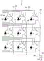
图1是车辆的驾驶辅助装置的概略结构图。FIG. 1 is a schematic configuration diagram of a driving assistance device for a vehicle.
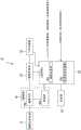
图2是例示出控制装置的结构的框图。FIG. 2 is a block diagram illustrating an example configuration of a control device.
图3是层积型摄像元件的剖视图。Fig. 3 is a cross-sectional view of a multilayer imaging device.
图4是说明摄像芯片的像素排列和单位区域的图。FIG. 4 is a diagram illustrating a pixel arrangement and a unit area of an imaging chip.
图5是说明单位区域的电路的图。FIG. 5 is a diagram illustrating a circuit of a unit area.
图6是表示摄像元件的功能结构的框图。FIG. 6 is a block diagram showing a functional configuration of an imaging element.
图7是例示出摄像头的结构的框图。FIG. 7 is a block diagram illustrating an example configuration of a camera.
图8是将包含有焦点检测像素线的一部分的区域放大的图。FIG. 8 is an enlarged view of a region including a part of a focus detection pixel line.
图9是例示出具有摄像元件的摄像头的结构的框图。FIG. 9 is a block diagram illustrating an example configuration of a camera having an imaging element.
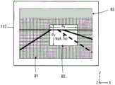
图10是例示出摄像芯片的成像面、摄像区域及关注区域、以及休止区域的图。10 is a diagram illustrating an example of an imaging surface of an imaging chip, an imaging region, a region of interest, and a rest region.
图11是说明控制部执行的摄像头的控制处理流程的流程图。FIG. 11 is a flowchart illustrating the flow of camera control processing executed by the control unit.
图12是说明初始设定处理的详细内容的流程图。FIG. 12 is a flowchart illustrating details of initial setting processing.
图13是例示出初始设定值的表的图。FIG. 13 is a diagram illustrating an example of a table of initial setting values.
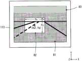
图14是例示出摄像芯片的成像面、摄像区域及关注区域、以及休止区域的图。FIG. 14 is a diagram illustrating an example of an imaging surface of an imaging chip, an imaging region, a region of interest, and a rest region.
图15是例示出摄像芯片的成像面、摄像区域及关注区域、以及休止区域的图。FIG. 15 is a diagram illustrating an imaging surface of an imaging chip, an imaging region, a region of interest, and a rest region.
图16是例示出摄像芯片的成像面、摄像区域及关注区域、以及休止区域的图。FIG. 16 is a diagram illustrating an example of an imaging surface of an imaging chip, an imaging region, a region of interest, and a rest region.
图17是说明行驶辅助设定处理的详细内容的流程图。FIG. 17 is a flowchart illustrating the details of driving assistance setting processing.
图18是说明标志Em的图。Fig. 18 is a diagram illustrating the flag Em.
图19是说明距离Z的图。FIG. 19 is a diagram illustrating the distance Z. FIG.
图20的(a)是例示出在一般道路的交叉路口右转的情况下的关注区域的位置移动以及尺寸变化的图。图20的(b)是例示出在高速公路上一边加速一边变道的情况下的关注区域的位置移动以及尺寸变化的图。(a) of FIG. 20 is a diagram illustrating an example of the positional movement and size change of the attention area when turning right at an intersection of a general road. (b) of FIG. 20 is a diagram illustrating an example of the position shift and size change of the region of interest when the vehicle changes lanes while accelerating on an expressway.
图21是说明转向灯方向和关注区域的尺寸变更的图。FIG. 21 is a diagram explaining changes in the direction of the turn signal and the size of the region of interest.
图22是说明变形例1的转向灯开关操作时的处理的流程图。FIG. 22 is a flowchart illustrating processing performed when a winker switch is operated in
图23是示意性地示出摄像芯片的成像面上的图像的图。FIG. 23 is a diagram schematically showing an image on an imaging surface of an imaging chip.
图24是说明控制部执行的摄像头的控制处理的整体流程的流程图。24 is a flowchart illustrating the overall flow of camera control processing executed by the control unit.
图25是说明摄像条件设定处理的详细内容的流程图。FIG. 25 is a flowchart illustrating details of imaging condition setting processing.
图26是例示出第1行驶环境变化的情况下的处理的流程图。FIG. 26 is a flowchart illustrating an example of processing when the first running environment changes.
图27是示意性地示出摄像芯片的成像面上的图像的图。FIG. 27 is a diagram schematically showing an image on an imaging surface of an imaging chip.
图28是例示出第2行驶环境变化的情况下的处理的流程图。FIG. 28 is a flowchart illustrating an example of processing when the second running environment changes.
图29是示意性地示出摄像芯片的成像面上的图像的图,图29的(a)是远光灯时的图,图29的(b)是近光灯时的图。29 is a diagram schematically showing an image on an imaging surface of an imaging chip, FIG. 29( a ) is a diagram at high beam, and FIG. 29( b ) is a diagram at low beam.
图30是例示出第3行驶环境变化的情况下的处理的流程图。FIG. 30 is a flowchart illustrating an example of processing when the third traveling environment changes.
图31是示意性地示出摄像芯片的成像面上的图像的图。FIG. 31 is a diagram schematically showing an image on an imaging surface of an imaging chip.
图32是例示出第4行驶环境变化的情况下的处理的流程图。FIG. 32 is a flowchart illustrating an example of processing when the fourth running environment changes.
图33是示意性地示出摄像芯片的成像面上的图像的图。FIG. 33 is a diagram schematically showing an image on an imaging surface of an imaging chip.
图34是例示出第5行驶环境变化的情况下的处理的流程图。FIG. 34 is a flowchart illustrating an example of processing when the fifth running environment changes.
图35是示意性地示出摄像芯片的成像面上的图像的图,图35的(a)是变道前的图,图35的(b)是变道中的图。35 is a diagram schematically showing an image on an imaging surface of an imaging chip, FIG. 35( a ) is a diagram before a lane change, and FIG. 35( b ) is a diagram during a lane change.
图36是表示第3实施方式的摄像系统的结构的框图。FIG. 36 is a block diagram showing the configuration of an imaging system according to a third embodiment.
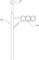
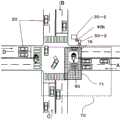
图37是例示出交叉路口处的信号机的配置的图。FIG. 37 is a diagram illustrating an example of the arrangement of traffic lights at intersections.
图38是例示出汽车用的信号机的图。FIG. 38 is a diagram illustrating an example of a traffic signal for an automobile.
图39是说明由汽车的控制部进行的控制的流程图。Fig. 39 is a flowchart illustrating control performed by the control unit of the vehicle.
图40的(a)是说明汽车的位置关系的图,图40的(b)是示意性地示出前方摄像头的被摄体像的图,图40的(c)是示意性地示出后方摄像头的被摄体像的图。(a) of FIG. 40 is a diagram illustrating the positional relationship of a car, (b) of FIG. 40 is a diagram schematically showing a subject image of a front camera, and (c) of FIG. 40 is a diagram schematically showing a rear A diagram of the camera's subject image.
图41是说明由信号机的控制部进行的控制的流程图。Fig. 41 is a flowchart illustrating the control performed by the control unit of the traffic signal.
图42是说明汽车用的信号机的摄像部的控制的图。FIG. 42 is a diagram illustrating control of an imaging unit of a traffic signal for an automobile.
图43是说明汽车用的信号机的摄像部的控制的图。FIG. 43 is a diagram illustrating control of an imaging unit of a traffic signal for an automobile.
图44是说明行人用的信号机的摄像部的控制的图。Fig. 44 is a diagram illustrating control of an imaging unit of a traffic signal for pedestrians.
图45的(a)是例示出由行人用的信号机的摄像部得到的摄像场景的图,图45的(b)是说明摄像条件的设定的图。(a) of FIG. 45 is a diagram illustrating an example of an imaging scene obtained by an imaging unit of a traffic signal for pedestrians, and (b) of FIG. 45 is a diagram illustrating setting of imaging conditions.
图46是例示出由汽车用的信号机的摄像部得到的摄像场景的图。FIG. 46 is a diagram illustrating an example of an imaging scene obtained by an imaging unit of a traffic signal for an automobile.
具体实施方式Detailed ways
以下,参照附图说明用于实施本发明的方式。Hereinafter, modes for implementing the present invention will be described with reference to the drawings.
(第1实施方式)(first embodiment)
<摄像头的使用情况><Camera Usage>
图1是搭载有本发明的第1实施方式的摄像头3的车辆1的驾驶辅助装置2的概略结构图。图1中,在汽车等车辆1上搭载有驾驶辅助装置2。驾驶辅助装置2由摄像头3、控制装置4、第1行驶控制单元5和第2行驶控制单元6等构成。1 is a schematic configuration diagram of a driving
此外,在本说明书中说明以内燃机为驱动源的例子,但也可以以电动机为驱动源,还可以是以内燃机和电动机为驱动源、所谓的混合动力式。In addition, although an example in which an internal combustion engine is used as a driving source is described in this specification, an electric motor may be used as a driving source, or a so-called hybrid type using an internal combustion engine and an electric motor as driving sources may also be used.
摄像头3具备具有多个透镜的摄像光学系统、和摄像元件(在本实施方式中为层积型摄像元件(参照图3)),摄像头3例如安装在车室内的车顶前方。摄像头3朝向车辆1的前方,其安装高度(地面到摄像头3的距离)被调整为例如1.4(m)。摄像头3获取车辆1的行进方向的图像,基于所获取的图像来进行到摄影画面内的多个位置处的各被摄体(对象物)的距离测定(测距)。距离测定通过使用了来自层积型摄像元件所具备的焦点检测用像素的图像信号的测距运算来计算。关于焦点检测用像素及测距将在后叙述。由摄像头3获取的图像的数据及测距数据被发送到控制装置4。此外,也可以在车外设置摄像头3,还可以使车内及车外的摄像头3协作,只要适当设定摄像头3的数量即可。列举一例,可以是,对于后述的白线检测使用车外的摄像头3,对于对象物和障碍物的识别通过使车内及车外的摄像头3协作来进行。The
如图2所例示那样,控制装置4包含CPU4a及存储部4b。CPU4a基于存储在存储部4b中的各种程序并使用存储在存储部4b中的控制参数和基于后述的各传感器得到的检测信号等来进行各种运算。As illustrated in FIG. 2 , the
第1行驶控制单元5基于来自控制装置4的指示来进行定速行驶控制及跟随行驶控制。定速行驶控制是基于规定的控制程序使车辆1以固定速度行驶的控制。跟随行驶控制是在进行定速行驶控制时,在通过控制装置4识别出的前行车辆的速度为对车辆1设定的目标速度以下的情况下,以相对于前行车辆保持固定的车间距离的状态行驶的控制。The first
第2行驶控制单元6基于来自控制装置4的指示来进行驾驶辅助控制。驾驶辅助控制是如下控制:基于规定的控制程序,以使车辆1沿道路行驶的方式向操舵控制装置9输出转向控制信号,或以使车辆1避免与对象物碰撞的方式向制动控制装置8输出制动控制信号等。The second
图1中还图示出节气门控制装置7、制动控制装置8、操舵控制装置9、方向盘10、转向灯开关11、车速传感器12、偏航率传感器(yaw rate sensor)13、显示装置14、GPS装置15、换挡杆位置检测装置16和麦克风17。Figure 1 also illustrates a throttle control device 7, a
此外,变光开关18和降雨传感器19不是第1实施方式中必须具有的结构。In addition, the
节气门控制装置7根据加速踏板7a的踏入量来控制未图示的节气门阀的开度。另外,节气门控制装置7也根据从第1行驶控制单元5发送来的节气门控制信号来进行对上述节气门阀的开度控制。节气门控制装置7还将表示加速踏板7a的踏入量的信号发送到控制装置4。The throttle control device 7 controls the opening degree of a throttle valve (not shown) according to the depression amount of the accelerator pedal 7a. In addition, the throttle control device 7 also controls the opening degree of the throttle valve based on the throttle control signal sent from the first
制动控制装置8根据制动踏板8a的踏入量来控制未图示的制动阀的开度。另外,制动控制装置8也根据来自第2行驶控制单元6的制动控制信号来进行对上述制动阀的开度控制。制动控制装置8还将表示制动踏板8a的踏入量的信号发送到控制装置4。The
操舵控制装置9根据方向盘10的旋转角来控制未图示的转向装置的舵角。另外,操舵控制装置9也根据来自第2行驶控制单元6的转向控制信号来进行上述转向装置的舵角控制。操舵控制装置9还将表示方向盘10的旋转角的信号分别发送到第1行驶控制单元5和控制装置4。The
转向灯开关11是用于使未图示的转向灯(方向指示灯:winker)装置工作的开关。转向灯装置是表示车辆1的前进路线变更的闪光装置。当由车辆1的乘员操作转向灯开关11时,来自转向灯开关11的操作信号分别被发送到转向灯装置、第2行驶控制单元6以及控制装置4。车速传感器12检测车辆1的车速V,并将检测信号分别发送到第1行驶控制单元5、第2行驶控制单元6和控制装置4。The winker switch 11 is a switch for operating a winker (winker) device (not shown). The turn signal device is a flashing device indicating a change in the course of the
偏航率传感器13检测车辆1的偏航率,并将检测信号分别发送到第2行驶控制单元6和控制装置4。偏航率是车辆1的向转向方向的旋转角的变化速度。显示装置14显示表示基于第1行驶控制单元5及第2行驶控制单元6的控制状态的信息等。显示装置14由例如向前挡风玻璃投射信息的HUD(Head Up Display:抬头显示器)构成。此外,作为显示装置14也可以利用未图示的导航装置的显示部。The yaw rate sensor 13 detects the yaw rate of the
GPS装置15接收来自GPS卫星的电波,并利用载于电波的信息来进行规定的运算,由此计算出车辆1的位置(纬度、经度等)。由GPS装置15计算出的位置信息被发送到未图示的导航装置和控制装置4。换挡杆位置检测装置16检测由车辆1的乘员操作的未图示的换挡杆的位置(例如,停车(P)、倒车(R)、前进(D)等)。由换挡杆位置检测装置16检测出的换挡杆的位置信息被发送到控制装置4。The
麦克风17由例如前方麦克风、右侧方麦克风和左侧方麦克风构成。前方麦克风具有专门收集车辆1的前方声音的指向性。右侧方麦克风具有专门收集车辆1的右侧方声音的指向性。左侧方麦克风具有专门收集车辆1的左侧方声音的指向性。由麦克风17所收集的各声音信息(前方、右侧方、左侧方)分别被发送到控制装置4。The
<对象物的检测><Detection of objects>
控制装置4为了检测车辆1的行驶道路及对象物而对来自摄像头3的图像如以下那样进行图像处理。首先,控制装置4基于摄影画面内的多个位置处的测距数据生成距离图像(进深分布图像)。控制装置4基于距离图像的数据进行周知的分组(grouping)处理,与预先存储于存储部4b中的三维道路形状数据、侧壁数据、对象物数据等的范围(window)进行比较,来检测白线数据(包括沿着道路的白线数据以及横贯道路的白线(停止线:交叉路口信息)数据)、沿着道路存在的护栏、路缘石等的侧壁数据,并且将对象物及障碍物分类为两轮车、普通车辆、大型车辆、行人、电线柱子等及其他对象物来进行检测。The
在本说明书中,将在行驶道路上标划的白色或黄色的标线称为白线。另外,称为白线的也包含实线及虚线。In this specification, a white or yellow marking line drawn on a driving road is called a white line. In addition, what is called a white line also includes a solid line and a dotted line.
<驾驶辅助><Driving assistance>
控制装置4基于如上述那样检测到的各信息、即白线数据、护栏侧壁数据、及对象物数据的各数据来识别行驶道路和成为障碍的对象物及障碍物,并基于识别结果来使第2行驶控制单元6进行上述驾驶辅助控制。即,使车辆1沿着道路行驶,并避免车辆1与对象物碰撞。The
<行驶控制><Driving Control>
控制装置4例如通过以下4种方式进行本车行进路线的推定。The
(1)基于白线进行的本车行进路线推定(1) Estimation of the vehicle's travel route based on the white line
在从由摄像头3获取的图像得到行驶道路的左右两侧或左右某一单侧的白线数据、且能够从这些白线数据推定出车辆1正在行驶的车道的形状的情况下,控制装置4考虑车辆1的宽度、车辆1当前在车道内的位置而推定本车行进路线与白线并行。When the white line data on the left and right sides or one of the left and right sides of the driving road is obtained from the image acquired by the
(2)基于护栏、路缘石等的侧壁数据进行的本车行进路线推定(2) Estimation of the vehicle's travel route based on side wall data such as guardrails and curbs
在从由摄像头3获取的图像得到行驶道路的左右两侧或左右某一单侧的侧壁数据、且能够从这些侧壁数据推定出车辆1正在行驶的车道的形状的情况下,控制装置4考虑车辆1的宽度、车辆1当前在车道内的位置而推定本车行进路线与侧壁并行。When the side wall data of the left and right sides or one of the left and right sides of the driving road is obtained from the image acquired by the
(3)基于前行车辆轨迹进行的本车行进路线推定(3) Estimation of the vehicle's travel route based on the trajectory of the preceding vehicle
控制装置4基于存储在存储部4b中的前行车辆的过去的行驶轨迹来推定本车行进路线。前行车辆是指与车辆1在相同方向行驶的对象物中的、距离车辆1最近的车辆。The
(4)基于车辆1的行驶轨迹进行的本车行进路线推定(4) Estimation of the traveling route of the own vehicle based on the traveling trajectory of the
控制装置4基于车辆1的驾驶状态来推定本车行进路线。例如,使用基于由偏航率传感器13检测到的检测信号、和由车速传感器12检测到的检测信号得到的转向曲率来推定本车行进路线。转向曲率Cua通过Cua=dψ/dt/V来计算。dψ/dt是上述偏航率(向转向方向的旋转角的变化速度),V是车辆1的车速。The
控制装置4遵照存储在存储部4b中的规定的行驶控制程序,针对每个上述对象物而基于本车行进路线来推定对象物所存在的位置处的车辆1的行驶区域,对该行驶区域和对象物位置进行比较,判定各个对象物是否处于行驶区域内。控制装置4还基于摄像头3的摄像结果来识别上述前行车辆。即,控制装置4从存在于行驶区域内且沿同方向(与车辆1相同的方向)行驶的对象物中将距离车辆1最近的车辆作为前行车辆。The
控制装置4将前行车辆与车辆1之间的车间距离信息、及前行车辆的车速信息作为车外信息输出到第1行驶控制单元5。在此,前行车辆的车速信息根据按每规定时间获取的车辆1的车速V、和基于与车速V的获取定时同步地按每上述规定时间由摄像头3获取的图像而测距到的摄影画面内的距前行车辆的距离(车间距离)的变化来计算出。The
第1行驶控制单元5以使由车速传感器12检测到的车速V收敛于预先设置的规定车速(目标速度)的方式向节气门控制装置7发送节气门控制信号。由此,节气门控制装置7对未图示的节气门阀的开度进行反馈控制,从而使车辆1自动地进行定速行驶。The first
另外,当在进行定速状态的行驶控制时从控制装置4输入的前行车辆的车速信息为对车辆1设定的目标速度以下的情况下,第1行驶控制单元5基于从控制装置4输入的车间距离信息向节气门控制装置7发送节气门控制信号。具体而言,第1行驶控制单元5基于从车辆1到前行车辆的车间距离以及前行车辆的车速、和车辆1的车速V来设定合适的车间距离的目标值,以使基于由摄像头3获取的图像而测距到的车间距离收敛于上述车间距离的目标值的方式向节气门控制装置7发送节气门控制信号。由此,节气门控制装置7对未图示的节气门阀的开度进行反馈控制,来使车辆1相对于前行车辆进行跟随行驶。In addition, when the vehicle speed information of the preceding vehicle input from the
<层积型摄像元件的说明><Description of multilayer image sensor>
对上述摄像头3中具备的层积型摄像元件100进行说明。此外,该层积型摄像元件100是本申请的申请人之前申请并被国际公开的WO13/164915号记载的元件。图3是层积型摄像元件100的剖视图。摄像元件100具备:输出与入射光对应的像素信号的背面照射型摄像芯片113、处理像素信号的信号处理芯片111、和存储像素信号的存储芯片112。这些摄像芯片113、信号处理芯片111及存储芯片112被层积,并通过Cu等具有导电性的凸块109而彼此电连接。The
此外,如图示那样,入射光主要向空心箭头所示的Z轴正向入射。在本实施方式中,将摄像芯片113中,入射光所入射的一侧的面称为背面(成像面)。另外,如坐标轴所示那样,将与Z轴正交的纸面左方作为X轴正向,将与Z轴及X轴正交的纸面近前方向作为Y轴正向。在以下的若干图中,以图3的坐标轴为基准来显示坐标轴以判明各图的朝向。In addition, as shown in the figure, the incident light mainly enters in the normal direction of the Z-axis indicated by the hollow arrow. In the present embodiment, the surface of the
摄像芯片113的一例是背面照射型的MOS图像传感器。PD层106配置在布线层108的背面侧。PD层106具有二维地配置、且蓄积与入射光相应的电荷的多个PD(光电二极管)104、以及与PD104对应地设置的晶体管105。An example of the
在PD层106中的入射光的入射侧隔着钝化膜103设有彩色滤光片102。彩色滤光片102具有使彼此不同的波段透射的多种类型,与PD104各自对应地具有特定排列。关于彩色滤光片102的排列将在后叙述。彩色滤光片102、PD104及晶体管105的组形成一个像素。The
在彩色滤光片102中的入射光的入射侧,与各个像素对应地设有微透镜101。微透镜101朝向对应的PD104会聚入射光。On the incident side of the incident light in the
布线层108具有将来自PD层106的像素信号向信号处理芯片111传送的布线107。布线107可以为多层,此外,也可以设置无源元件及有源元件。The
在布线层108的表面配置有多个凸块109。该多个凸块109与在信号处理芯片111的相对面设置的多个凸块109对位,通过对摄像芯片113和信号处理芯片111进行加压等,使对位后的凸块109彼此接合而电连接。A plurality of
同样地,在信号处理芯片111与存储芯片112的彼此相对的面上配置有多个凸块109。这些凸块109彼此对位,通过对信号处理芯片111和存储芯片112进行加压等,使对位后的凸块109彼此接合而电连接。Similarly, a plurality of
此外,凸块109间的接合不限于基于固相扩散的Cu凸块接合,也可以采用基于钎焊熔融的微凸块结合。另外,凸块109只要例如对后述的一个区块设置一个的程度即可。因此,凸块109的大小可以比PD104的间距大。另外,在像素所排列的像素区域以外的外围区域也可以同时设置比与像素区域对应的凸块109大的凸块。In addition, the bonding between the
信号处理芯片111具有将分别设置在表背面上的电路彼此连接的TSV(硅贯穿电极)110。TSV110优选设置在外围区域。另外,TSV110也可以还设置在摄像芯片113的外围区域、存储芯片112。The
图4是说明摄像芯片113的像素排列和单位区域131的图。尤其是,示出了从背面(成像面)侧观察摄像芯片113的情况。在像素区域中呈矩阵状排列有例如2000万个以上的像素。在图4的例子中,相邻的4像素×4像素的16像素形成一个单位区域131。图中的格线示出相邻的像素被分组而形成单位区域131的概念。形成单位区域131的像素的数量不限于此,可以是1000个左右,例如32像素×64像素,还可以是其以上或以下。FIG. 4 is a diagram illustrating a pixel arrangement of the
如像素区域的局部放大图所示那样,图4的单位区域131在上下左右内置有四个所谓的拜耳阵列,该拜耳阵列由绿色像素Gb、Gr、蓝色像素B及红色像素R这4个像素构成。绿色像素Gb、Gr是作为彩色滤光片102而具有绿色滤光片的像素,接收入射光中的绿色波段的光。同样地,蓝色像素B是作为彩色滤光片102而具有蓝色滤光片的像素,接收蓝色波段的光,红色像素R是作为彩色滤光片102而具有红色滤光片的像素,接收红色波段的光。As shown in the partially enlarged view of the pixel area, the
在本实施方式中,以对1区块至少包含一个单位区域131的方式定义多个区块,对各区块能够通过彼此不同的控制参数来控制各区块中包含的像素。也就是说,能够通过某个区块中包含的像素组和其他区块中包含的像素组来获取摄像条件不同的摄像信号。关于控制参数的例子,为帧率(frame rate)、增益、间除率、将像素信号相加的相加行数或相加列数、电荷的蓄积时间或者蓄积次数、数字化的位数(字长)等。摄像元件100不仅能够自如地进行行方向(摄像芯片113的X轴方向)上的间除,还能够自如地进行列方向(摄像芯片113的Y轴方向)上的间除。而且,控制参数也可以是从像素获取图像信号后的图像处理中的参数。In the present embodiment, a plurality of blocks are defined so as to include at least one
图5是说明单位区域131中的电路的图。在图5的例子中,通过相邻的3像素×3像素的9个像素形成一个单位区域131。此外,如上述那样,单位区域131中包含的像素的数量不限于此,也可以是其以下或其以上。单位区域131的二维位置由附图标记A~I表示。FIG. 5 is a diagram illustrating circuits in the
单位区域131中包含的像素的复位晶体管构成为能够按每个像素单独地导通、截止。在图5中,设有使像素A的复位晶体管导通、截止的复位布线300,使像素B的复位晶体管导通、截止的复位布线310与上述复位布线300单独地设置。同样地,使像素C的复位晶体管导通、截止的复位布线320与上述复位布线300、310单独地设置。对于其他的像素D至像素I也设有用于使各个复位晶体管导通、截止的专用的复位布线。The reset transistors of the pixels included in the
单位区域131中包含的像素的传输晶体管也构成为能够按每个像素单独地导通、截止。在图5中,使像素A的传输晶体管导通、截止的传输布线302、使像素B的传输晶体管导通、截止的传输布线312、使像素C的传输晶体管导通、截止的传输布线322单独地设置。对于其他的像素D至像素I也设有用于使各个传输晶体管导通、截止的专用的传输布线。The transfer transistors of the pixels included in the
而且,单位区域131中包含的像素的选择晶体管也构成为能够按每个像素单独地导通、截止。在图5中,使像素A的选择晶体管导通、截止的选择布线306、使像素B的选择晶体管导通、截止的选择布线316、使像素C的选择晶体管导通、截止的选择布线326单独地设置。对于其他的像素D至像素I也设有用于使各个选择晶体管导通、截止的专用的选择布线。Furthermore, the selection transistors of the pixels included in the
此外,电源布线304在单位区域131所包含的像素A至像素I中共用共通地连接。同样地,输出布线308在单位区域131所包含的像素A至像素I中共通地连接。另外,电源布线304在多个单位区域间共通地连接,但输出布线308按每个单位区域131单独地设置。负载电流源309向输出布线308供给电流。负载电流源309可以设置在摄像芯片113侧,也可以设置在信号处理芯片111侧。In addition, the
通过使单位区域131的复位晶体管及传输晶体管单独地导通、截止,能够对单位区域131中含有的像素A至像素I独立地控制包含电荷的蓄积开始时间、蓄积结束时间、传输定时在内的电荷蓄积。另外,通过使单位区域131的选择晶体管单独地导通、截止,能够经由公用的输出布线308输出各像素A至像素I的像素信号。By individually turning on and off the reset transistor and the transfer transistor of the
在此,对单位区域131中包含的像素A至像素I以相对于行及列按有规则的顺序控制电荷蓄积的、所谓滚动快门方式是公知的。若通过滚动快门方式按行选择像素后指定列,则在图5的例子中按“ABCDEFGHI”的顺序输出像素信号。Here, a so-called rolling shutter method is known in which charge accumulation is controlled in regular order with respect to rows and columns for pixels A to I included in the
通过像这样以单位区域131为基准构成电路,能够按每个单位区域131控制电荷蓄积时间。换言之,能够分别输出在单位区域131间以不同的帧率得到的像素信号。另外,摄像芯片113中,在使一部分区域所包含的单位区域131进行电荷蓄积(摄像)的期间使其他区域所包含的单位区域131休止,由此能够仅在摄像芯片113的规定区域进行摄像,能够输出其像素信号。而且,也能够在帧间切换进行电荷蓄积(摄像)的区域(蓄积控制的对象区域),来在摄像芯片113的不同区域进行逐步摄像,输出像素信号。By configuring the circuit based on the
图6是表示与图5例示出的电路对应的摄像元件100的功能结构的框图。模拟的多路复用器411按顺序选择形成单位区域131的9个PD104,使各个像素信号输出到与该单位区域131对应地设置的输出布线308。多路复用器411与PD104一起形成在摄像芯片113上。FIG. 6 is a block diagram showing a functional configuration of the
经由多路复用器(multiplexer)411输出的像素信号通过形成于信号处理芯片111上的、进行相关双采用(CDS)及模拟/数字(A/D)转换的信号处理电路412进行CDS及A/D转换。A/D转换后的像素信号被交付到信号分离器(demultiplexer)413,并保存到与各个像素对应的像素存储器414中。信号分离器413及像素存储器414形成于存储芯片112上。The pixel signal output through the multiplexer (multiplexer) 411 is formed on the
运算电路415对保存在像素存储器414中的像素信号进行处理并交付到后级的图像处理部。运算电路415可以设置在信号处理芯片111上,也可以设置在存储芯片112上。The
此外,在图6中示出了一个单位区域131量的连接,但实际上它们按每个单位区域131存在且并行地动作。但是,运算电路415可以不按每个单位区域131而存在,例如可以是,一个运算电路415一边按顺序参照与各个单位区域131对应的像素存储器414的值一边依序进行处理。In addition, although the connection of one
如上述那样,与单位区域131各自对应地设有输出布线308。由于摄像元件100层积有摄像芯片113、信号处理芯片111及存储芯片112,所以通过对这些输出布线308使用采用了凸块109的芯片间电连接,能够不会在面方向上增大各芯片地,对布线进行排布。As described above, the
<测距的说明><Description of distance measurement>
图7是例示出摄像元件100的成像面中的焦点检测用像素的位置的图。在本实施方式中,沿着摄像芯片113的X轴方向(水平方向)离散地并列设有焦点检测用像素。在图7的例子中,按规定的间隔设有15条焦点检测像素线60。构成焦点检测像素线60的焦点检测用像素输出测距用的图像信号。摄像芯片113中在焦点检测像素线60以外的像素位置设有通常的摄像用像素。摄像用像素输出监视车外的移动体和障碍物的车外监视用的图像信号。FIG. 7 is a diagram illustrating an example of the positions of focus detection pixels on the imaging surface of the
图8是将包含上述焦点检测像素线60中的一条线的一部分的区域放大的图。图8中,例示出红色像素R、绿色像素G(Gb、Gr)、蓝色像素B、焦点检测用像素S1以及焦点检测用像素S2。红色像素R、绿色像素G(Gb、Gr)以及蓝色像素B按照上述的拜耳阵列的规则排列。FIG. 8 is an enlarged view of a region including a part of one of the focus
对于红色像素R、绿色像素G(Gb、Gr)以及蓝色像素B例示出的正方形状的区域表示摄像用像素的受光区域。各摄像用像素接收从摄像光学系统31(图9)的射出光瞳通过的光束。即,红色像素R、绿色像素G(Gb、Gr)以及蓝色像素B分别具有正方形状的掩模开口部,从这些掩模开口部通过了的光到达至摄像用像素的受光部。The square-shaped regions illustrated for the red pixel R, the green pixel G (Gb, Gr), and the blue pixel B represent light-receiving regions of the imaging pixels. Each pixel for imaging receives the light beam which passed through the exit pupil of the imaging optical system 31 (FIG. 9). That is, each of the red pixel R, the green pixel G (Gb, Gr), and the blue pixel B has a square mask opening, and light passing through these mask openings reaches the light receiving unit of the imaging pixel.
此外,红色像素R、绿色像素G(Gb、Gr)以及蓝色像素B的受光区域(掩模开口部)的形状不限于四边形,也可以是例如圆形。In addition, the shape of the light-receiving regions (mask openings) of the red pixel R, the green pixel G (Gb, Gr), and the blue pixel B is not limited to a quadrangle, and may be, for example, a circle.
对于焦点检测用像素S1以及焦点检测用像素S2例示出的半圆形状的区域表示焦点检测用像素的受光区域。即,焦点检测用像素S1在图8中在像素位置的左侧具有半圆形状的掩模开口部,通过了该掩模开口部的光到达至焦点检测用像素S1的受光部。另一方面,焦点检测用像素S2在图8中在像素位置的右侧具有半圆形状的掩模开口部,通过了该掩模开口部的光到达至焦点检测用像素S2的受光部。像这样,焦点检测用像素S1以及焦点检测用像素S2分别接收从摄像光学系统31(图9)的射出光瞳的不同区域通过的一对光束。The semicircle-shaped area illustrated for the focus detection pixel S1 and the focus detection pixel S2 represents a light receiving area of the focus detection pixel. That is, the focus detection pixel S1 has a semicircular mask opening on the left side of the pixel position in FIG. 8 , and light passing through the mask opening reaches the light receiving unit of the focus detection pixel S1 . On the other hand, the focus detection pixel S2 has a semicircular mask opening on the right side of the pixel position in FIG. 8 , and light passing through the mask opening reaches the light receiving unit of the focus detection pixel S2 . In this way, the pixels S1 for focus detection and the pixels S2 for focus detection respectively receive a pair of light beams passing through different regions of the exit pupil of the imaging optical system 31 ( FIG. 9 ).
此外,摄像芯片113中的焦点检测像素线的位置不限于图7所例示的位置。另外,关于焦点检测像素线的数量也不限于图7的例子。而且,焦点检测用像素S1及焦点检测用像素S2中的掩模开口部的形状不限于半圆形,也可以为例如将摄像用像素R、摄像用像素G、摄像用像素B中的四边形状受光区域(掩模开口部)沿横向分割而得到的长方形状。In addition, the positions of the focus detection pixel lines in the
另外,摄像芯片113中的焦点检测像素线也可以沿着摄像芯片113的Y轴方向(铅锤方向)排列地设有焦点检测用像素。如图8那样将摄像用像素和焦点检测用像素二维地排列而成的摄像元件是公知的,省略这些像素的详细图示及说明。In addition, the focus detection pixel lines in the
此外,在图8的例子中,说明了焦点检测用像素S1、S2分别接收焦点检测用的一对光束中的一方的结构、所谓的1PD构造。代替该结构,也可以是所谓的2PD构造,即,如例如日本特开2007-282107号公报所公开那样,焦点检测用像素分别接收焦点检测用的一对光束双方的结构。通过像这样成为2PD构造,从焦点检测用像素也能够读出图像数据,焦点检测像素不会成为缺陷像素。In addition, in the example of FIG. 8 , the structure in which the pixels S1 and S2 for focus detection each receive one of a pair of light beams for focus detection, a so-called 1PD structure, has been described. Instead of this structure, there may be a so-called 2PD structure, that is, a structure in which the pixels for focus detection respectively receive both of a pair of light beams for focus detection, as disclosed in, for example, Japanese Patent Application Laid-Open No. 2007-282107. By adopting such a 2PD structure, image data can be read from the focus detection pixels, and the focus detection pixels do not become defective pixels.
在本实施方式中,基于从焦点检测用像素S1及焦点检测用像素S2输出的测距用的图像信号来检测从摄像光学系统31(图9)的不同区域通过的一对光束所形成的一对像的像偏移量(相位差),由此运算摄像光学系统31的焦点调节状态(散焦量)。In this embodiment, a pair of light beams formed by a pair of light beams passing through different regions of the imaging optical system 31 ( FIG. 9 ) is detected based on image signals for distance measurement output from the focus detection pixel S1 and the focus detection pixel S2 . The amount of image shift (phase difference) of the object is used to calculate the focus adjustment state (defocus amount) of the imaging
通常,上述一对像在摄像光学系统31使对象物(例如前行车辆)的清晰像成像在比预定焦点面靠前的位置的所谓前焦点状态下彼此靠近,相反地在使对象物的清晰像成像在比预定焦点面靠后的位置的所谓后焦点状态下彼此远离。在预定焦点面处成像出对象物的清晰像的对焦状态时,上述一对像相对一致。因此,一对像的相对位置偏移量对应于到对象物的距离(进深信息)。Usually, the above-mentioned pair of images approach each other in a so-called front focus state in which the imaging
基于上述相位差的散焦量运算在摄像头领域是公知的,因此省略详细说明。在此,散焦量和到对象物的距离是一一对应的,因此能够通过按每个对象物求出散焦量来求出从摄像头3到各对象物的距离。即,能够在摄影画面的多个位置处分别进行到上述对象物的距离的测定(测距)。散焦量与到对象物的距离之间的关系预先被准备为数式或查找表(lookup table),并保存在非易失性存储器35b(图9)中。The calculation of the defocus amount based on the above-mentioned phase difference is well known in the field of cameras, and thus detailed description thereof will be omitted. Here, since the amount of defocus and the distance to the object are in one-to-one correspondence, the distance from the
<摄像头的说明><Explanation of camera>
图9是例示出具有上述摄像元件100的摄像头3的结构的框图。在图9中,摄像头3具有摄像光学系统31、摄像部32、图像处理部33、工作存储器34、控制部35以及记录部36。FIG. 9 is a block diagram illustrating an example configuration of the
摄像光学系统31将来自被摄场景的光束向摄像部32引导。摄像部32包含上述摄像元件100及驱动部32a,对通过摄像光学系统31而成像在摄像芯片113上的对象物的像进行光电转换。驱动部32a生成为了在摄像元件100(摄像芯片113)中以上述区块为单位来进行独立的蓄积控制所需的驱动信号。上述区块的位置和形状、其范围、蓄积时间等的指示被从控制部35发送到驱动部32a。The imaging
图像处理部33与工作存储器34协作地对通过摄像部32摄像得到的图像数据进行图像处理。图像处理部33在进行例如轮廓强调处理和伽马校正等的图像处理的基础上,还进行对图像中包含的对象物的颜色检测。The
工作存储器34临时存储图像处理前后的图像数据等。记录部36在由非易失性存储器等构成的存储介质中记录图像数据等。控制部35由例如CPU构成,根据来自控制装置4的控制信号来控制摄像头3的整体动作。例如,基于通过摄像部32拍摄到的图像信号来进行规定的曝光运算,并向驱动部32a指示适当曝光所需要的摄像芯片113的蓄积时间。The
在控制部35中包含测距运算部35a和非易失性存储器35b。测距运算部35a如上述那样在摄影画面的多个位置处分别进行到上述对象物的距离测定(测距)。通过摄像头3获取到的图像数据及通过摄像头3计算出的测距数据被发送到控制装置4(图1)。非易失性存储器35b存储控制部35a执行的程序、以及测距所需的信息。The
<摄像元件的区块控制><Block Control of Imager>
控制装置4对摄像头3的摄像元件100(摄像芯片113)以上述区块为单位来进行独立的蓄积控制。因此,从车辆1的各部分向控制装置4输入以下的信号(图2)。The
(1)加速踏板7a的踏入量(1) Depression amount of the accelerator pedal 7a
从节气门控制装置7向控制装置4输入表示加速踏板7a的踏入量的信号。A signal indicating the depression amount of the accelerator pedal 7 a is input from the throttle control device 7 to the
(2)制动踏板8a的踏入量(2) Depression amount of the brake pedal 8a
从制动控制装置8向控制装置4输入表示制动踏板8a的踏入量的信号。A signal indicating the amount of depression of the brake pedal 8 a is input from the
(3)方向盘10的旋转角(3) The rotation angle of the
从操舵控制装置9向控制装置4输入表示方向盘10的旋转角的信号。方向盘10的旋转角与转向装置的舵角之比基于转向的齿轮速比(gear ratio)。A signal indicating the rotation angle of the
(4)车辆1的车速V(4) Vehicle speed V of
由车速传感器12检测到的检测信号被输入到控制装置4。A detection signal detected by the
(5)转向灯开关11的操作信号(5) Operation signal of turn signal switch 11
转向灯开关11的操作信号被输入到控制装置4。An operation signal of the winker switch 11 is input to the
(6)换挡杆的操作位置(6) Operating position of the shift lever
表示换挡杆位置检测装置16检测到的换挡杆的操作位置的信号被输入到控制装置4。A signal indicating the operating position of the shift lever detected by the shift lever position detection device 16 is input to the
(7)车辆1的位置信息(7) Location information of
由GPS装置15测量到的位置信息被从GPS装置15输入到控制装置4。Positional information measured by the
(8)车辆1周围的声音信息(8) Sound information around the
由麦克风17收集的来自车辆1的前方、右侧方、以及左侧方的声音信息分别被输入到控制装置4。Sound information from the front, right side, and left side of the
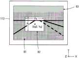
图10是例示出摄像芯片113的成像面、摄像芯片113中进行电荷蓄积(摄像)的区域(摄像区域81及关注区域82)、和不进行行方向及列方向的电荷蓄积(摄像)的区域(休止区域83)的图。关注区域82是以与摄像区域81不同的条件进行电荷蓄积(摄像)的区域。摄像芯片113中的摄像区域81、关注区域82的尺寸和位置也是摄像条件之一。FIG. 10 shows an example of the imaging surface of the
控制装置4对摄像区域81中包含的单位区域131以分别设定第1条件进行拍摄的方式进行控制,并且,对关注区域82中包含的单位区域131以分别设定第2条件进行拍摄的方式进行控制。另外,控制装置4使休止区域83中包含的单位区域131休止以使其不进行拍摄。The
此外,可以设置多个关注区域82,也可以在多个关注区域间使摄像条件不同。另外,也可以不设置休止区域83。In addition, a plurality of regions of
<流程图的说明><Description of flow chart>
以下,参照流程图(图11、图12、图17)来说明摄像区域81及关注区域82的确定方法。图11是说明控制装置4执行的摄像头3的控制处理的流程的流程图。用于执行图11的流程图的处理的程序保存在控制装置4的存储部4b中。控制装置4例如在从车辆1开始供给电源、发动机启动等时,起动进行图11所示的处理的程序。Hereinafter, a method of specifying the
在图11的步骤S10中,控制装置4判定是否为标志a=0。标志a是在初始设定结束的情况下设置为1、在初始设定尚未结束的情况下设置为0的标志。控制装置4在标志a=0的情况下将步骤S10判定为肯定而进入步骤S20,在标志a≠0的情况下将步骤S10判定为否定而进入步骤S30。In step S10 of FIG. 11 , the
在步骤S20中,控制装置4进行初始设定处理后进入步骤S30。关于初始设定处理的详细内容将在后叙述。在步骤S30中,控制装置4进行行驶辅助设定处理后进入步骤S40。在行驶辅助设定处理中,对摄像元件100确定摄像区域81及关注区域82。关于行驶辅助设定处理的详细内容将在后叙述。In step S20, the
在步骤S40中,控制装置4向摄像头3发送指示,分别以规定的条件驱动摄像元件100中的摄像区域81及关注区域82,使其进行图像获取。在本实施方式中,例如,控制装置4在车速V从0增加时,与摄像区域81相比将关注区域82的帧率设定得高,将增益设定得高,将间除率设定得低,将蓄积时间设定得短。由此,进行基于摄像头3的摄像,并且如上述那样在摄影画面的多个位置处进行距离测定(测距)。In step S40 , the
此外,不需要在摄像区域81与关注区域82之间使帧率、增益、间除率、蓄积时间等全部不同,可以仅使至少一个不同。另外,控制装置4也可以设定为对关注区域82不进行间除。In addition, it is not necessary to make all of the frame rate, gain, thinning-out rate, accumulation time, etc. different between the
在步骤S45中,控制装置4从摄像头3获取图像的数据及测距数据后进入步骤S50。在步骤S50中,控制装置4判定是否进行了显示信息的设定。控制装置4在进行了显示设定的情况下将步骤50判定为肯定并进入步骤S60。控制装置4在没有进行显示设定的情况下,将步骤50判定为否定并进入步骤S70。In step S45, the
在步骤S60中,控制装置4发送针对显示装置14(图1)的显示信息后进入步骤S70。显示信息是与在行驶辅助设定处理(S30)中判断得到的车辆1的状态相应的信息,例如在显示装置14上显示“停止中”、“紧急停车”、“右转”、“左转”这样的消息。In step S60, the
此外,也可以代替发送显示信息或者在发送显示信息的同时,向未图示的语音播放装置发送用于播放上述消息的语音信号。在该情况下,作为未图示的语音播放装置也可以使用未图示的导航装置的语音装置。In addition, instead of transmitting the display information or simultaneously with transmitting the display information, a voice signal for playing the above-mentioned message may be transmitted to a voice playback device not shown in the figure. In this case, an audio device of a navigation device (not shown) may be used as the audio playback device (not shown).
在步骤S70中,控制装置4判定是否实施了关闭操作。控制装置4当例如从车辆1接收到关闭信号(例如,发动机的关闭信号)时,将步骤S70判定为肯定,进行规定的关闭处理后结束图11的处理。控制装置4在例如没有从车辆1接收到关闭信号的情况下,将步骤S70判定为否定并进入步骤S80。在步骤S80中,控制装置4等待规定时间(例如0.1秒)后返回到步骤S30。在返回到步骤S30的情况下重复进行上述的处理。In step S70, the
<初始设定处理><Initial setting processing>
图12是说明图11的流程图的步骤S20(初始设定处理)的详细内容的流程图。在图12的步骤S21中,控制装置4从GPS装置15(图1)输入车辆1的位置信息后进入步骤S22。在步骤S22中,控制装置4基于位置信息中包含的纬度、经度来设置表示车辆1行驶的通行道是道路之左还是之右、即是左侧通行还是右侧通行的标志。具体而言,控制装置4基于纬度、经度来判断使用车辆1的国名。然后,参照未图示的数据库来设置表示该国的道路是左侧通行还是右侧通行的标志。表示国名与通行道左右之间的关系的数据库预先保存在存储部4b中。FIG. 12 is a flowchart illustrating the details of step S20 (initial setting processing) in the flowchart of FIG. 11 . In step S21 of FIG. 12 , the
在步骤S23中,控制装置4设置表示车辆1中的转向手柄(handle)(方向盘10)的安装位置(右或左)的标志后进入步骤S24。表示是右舵还是左舵的信息作为车辆1的规格信息而预先保存在存储部4b中。在步骤S24中,控制装置4基于图13所例示的表来确定初始设定值后进入步骤S25。此外,步骤S21和步骤S23的顺序可以调换。In step S23, the
根据图13,根据车辆1的方向盘10的安装位置(右或左)和道路的通行道的位置(右或左)的组合来准备“1”至“4”这四种初始设定值。在为右舵且左侧通行的情况下,初始设定值为“4”。According to FIG. 13 , four initial setting values "1" to "4" are prepared according to combinations of the mounting position (right or left) of the
在步骤S25中,控制装置4设置关注区域82的初始位置。关注区域82的初始位置为与初始设定值相应的位置。具体而言,控制装置4在初始设定值为“1”的情况下将关注区域82的初始位置设为(Xq1,Yq),在初始设定值为“2”的情况下将关注区域82的初始位置设为(Xq2,Yq),在初始设定值为“3”的情况下将关注区域82的初始位置设为(Xq3,Yq),在初始设定值为“4”的情况下将关注区域82的初始位置设为(Xq4,Yq)。In step S25 , the
本说明中,在表示摄像区域81的坐标系中,以关注区域82的中央坐标(Xq,Yq)来表示关注区域82的位置。图10例示出初始设定值为“4”的情况下的关注区域82,由于为右舵且左侧通行,所以以在左侧通行道中对驾驶员席侧(靠右)设定关注区域82的方式确定初始位置(Xq4,Yq)。In the present description, in the coordinate system representing the
图14例示出初始设定值为“1”的情况下的关注区域82,由于为左舵且右侧通行,所以以在右侧通行道中对驾驶员席侧(靠左)设定关注区域82的方式确定初始位置(Xq1,Yq)。Fig. 14 illustrates the
图15例示出初始设定值为“3”的情况下的关注区域82,由于为左舵且左侧通行,所以以在左侧通行道中对驾驶员席侧(靠左)设定关注区域82的方式确定初始位置(Xq3,Yq)。Fig. 15 illustrates the area of
图16例示出初始设定值为“2”的情况下的关注区域82,由于为右舵且右侧通行,所以以在右侧通行道中对驾驶员席侧(靠右)设定关注区域82的方式确定初始位置(Xq2,Yq)。Fig. 16 illustrates the
在图12的步骤S26中,控制装置4设置关注区域82的初始尺寸。本实施方式中,基于对象物(例如前行车辆)的大小(尺寸)来确定关注区域82的初始尺寸(Px(X轴方向)×Py(Y轴方向))。控制装置4在通过摄像头3获取的图像中包含前行车辆的情况下,基于由摄像芯片113拍摄到的前行车辆的像高、已知的摄像光学系统31的焦点距离、和通过测距得到的车辆1到前行车辆的距离L,来推定前行车辆的大小(尺寸)。然后,在从后方1(m)拍摄到推定大小(例如宽度3(m)×高度1.4(m))的前行车辆的情况下,将构成在摄像芯片113上得到的像的像素数(Px(X轴方向)×Py(Y轴方向))设为初始尺寸。In step S26 of FIG. 12 , the
Px及Py通过下式(1)、(2)计算出。Px and Py are calculated by the following formulas (1) and (2).
Px=ox×L…(1)Px=ox×L...(1)
Py=oy×L…(2)Py=oy×L...(2)
其中,ox为构成离开L(m)而由摄像芯片113拍摄到的前行车辆的像的X轴方向上的像素数。Oy为构成离开L(m)而由摄像芯片113拍摄到的前行车辆的像的Y轴方向上的像素数。L为车辆1到前行车辆的车间距离。Here, ox is the number of pixels in the X-axis direction constituting the image of the preceding vehicle captured by the
此外,在表示摄像区域81的坐标系中,表示初始位置的上述Yq相当于在拍摄到上述离开1(m)的前行车辆的情况下在摄像芯片113上得到的像的高度中心(在本例中为前行车辆的高度0.7(m)的部位)。In addition, in the coordinate system representing the
在步骤S27中,控制装置4发送针对显示装置14(图1)的显示信息,对标志a设置1,结束图12所示的处理。显示信息是表示初始设定处理已结束的信息,例如在显示装置14上显示“初始设定结束”这一消息。In step S27, the
<行驶辅助设定处理><Driving assistance setting process>
图17是说明行驶辅助设定处理的详细内容的流程图。在图17的步骤S310中,控制装置4在从换挡杆位置检测装置16(图1)输入的换挡杆的位置信息为“P”(停车)的情况下,将步骤S310判定为肯定并进入步骤S320。控制装置4在从换挡杆位置检测装置16(图1)输入的换挡杆的位置信息不为“P”的情况下,将步骤S310判定为否定并进入步骤S420。此外,在换挡杆为“N”(空档)的情况下也可以适用步骤S310的判断。FIG. 17 is a flowchart illustrating the details of driving assistance setting processing. In step S310 of FIG. 17 , when the position information of the shift lever input from the shift lever position detection device 16 ( FIG. 1 ) is “P” (Park), the
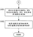
在步骤S320中,控制装置4从车速传感器12输入车速V后进入步骤S330。控制装置4根据例如车速V使关注区域82的帧率变化。如上述那样,在将关注区域82的帧率设定得比摄像区域81的帧率高的情况下,控制装置4在车速V越是增加时将关注区域82的帧率设定得越高,在车速V越是减小时将关注区域82的帧率设定得越低。该情况下,控制装置4也可以适用使关注区域82以外的摄像区域81的帧率也与车速V成比例这样的控制。在步骤S330中,控制装置4从制动控制装置8(图1)输入制动踏板8a的踏入量后进入步骤S340。In step S320, the
在步骤S340中,控制装置4基于车速V和制动踏板8a的踏入量(踏入角度)来判定是否为标志Em=0。标志Em是基于车速V和制动踏板8a的踏入量(踏入角度)的变化量而如图18所例示那样设置的标志。本实施方式中,将Em=1的情况判断为紧急制动(急刹车),将Em=0的情况判定为通常制动。控制装置4在Em=0的情况下将步骤S340判定为肯定并进入步骤S350。控制装置4在Em=1的情况下将步骤S340判定为否定并进入步骤S430。In step S340, the
此外,也可以代替制动踏板8a的踏入量(踏入角度)的变化量,基于未图示的制动阀的开度的变化量来判定Em=1。另外,也可以基于车速V的变化量来判定Em=1,还可以基于未图示的变速器的减速比的变化量来判定Em=1。In addition, Em=1 may be determined based on a change amount of the opening degree of a brake valve (not shown) instead of a change amount of the depression amount (depression angle) of the brake pedal 8 a. In addition, Em=1 may be determined based on the amount of change in the vehicle speed V, or Em=1 may be determined based on the amount of change in the speed reduction ratio of the transmission (not shown).
在步骤S350中,控制装置4从节气门控制装置7(图1)输入加速踏板7a的踏入量后进入步骤S360。步骤S360中,控制装置4从操舵控制装置9输入方向盘10的旋转角θ后进入步骤S370。在步骤S370中,控制装置4判定是否进行了转向操作。控制装置4在旋转角θ大于规定值的情况下将步骤S370判定为肯定并进入步骤S380,在旋转角θ为规定值以下的情况下将步骤S370判定为否定并进入步骤S440。In step S350, the
在步骤S380中,控制装置4基于方向盘10的旋转角θ和车速V,通过下式(3)计算出X轴方向上的关注区域82的移动量Xdist。In step S380 , the
Xdist=θ×(V×0.2)…(3)Xdist=θ×(V×0.2)…(3)
根据上式(3),转向装置的舵角(即方向盘10的旋转角θ)越大,另外车速V越大,则移动量Xdist越大。According to the above formula (3), the larger the rudder angle of the steering device (that is, the rotation angle θ of the steering wheel 10 ) and the larger the vehicle speed V, the larger the movement amount Xdist is.
在步骤S390中,控制装置4以在初始设定处理中设置的关注区域82的初始位置(XqN,Yq)为基础,通过下式(4)计算出行驶中的关注区域82的位置(X坐标)。In step S390, the
Xq=XqN+Xdist…(4)Xq=XqN+Xdist...(4)
其中,N是在初始设定处理中确定的初始设定值1~4中的某一个值。However, N is any one of the
Xdist是在步骤S380中计算出的X轴方向上的关注区域82的移动量,与X轴方向上的像素数对应。通过步骤S390的处理,关注区域82的位置与转向操作相应地变化。另外,关注区域82的位置还根据车速V的大小而变化。Xdist is the movement amount of the region of
在步骤S400中,控制装置4以在初始设定处理中设置的关注区域82的初始位置(XqN,Yq)为基础,通过下式(5)计算出行驶中的关注区域82的位置(Y坐标)。In step S400, the
Yq=Yq+P(Z)…(5)Yq=Yq+P(Z)...(5)
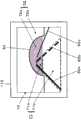
其中,P(Z)是Y轴方向上的关注区域82的移动量,是与进深Z(m)对应的Y轴方向上的像素数。例如,表示进深20(m)的道路的像在Y轴方向上相当于多少像素。进深Z与像素数之间的关系P(Z)预先保存在存储部4b(图2)中。Here, P(Z) is the movement amount of the
一般而言,在平坦的直线道路上拍摄行进方向的情况下,与摄像芯片113上的道路的像对应的Y轴方向上的像素数随着距离车辆1的进深Z(m)变深而增加。因此,使与拍摄上述离开1(m)的前行车辆的情况下的像的高度中心相当的Yq的值随着应关注的前行车辆变远(即进深Z变深)而增加。Generally speaking, when the traveling direction is captured on a flat straight road, the number of pixels in the Y-axis direction corresponding to the road image on the
控制装置4通过下式(6)来确定应关注的前行车辆的进深Z。The
Z=Za+Zb…(6)Z=Za+Zb...(6)
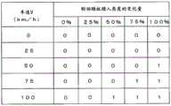
其中,Za是干燥道路上的制动距离(m),Zb是湿润的路面上的制动距离(m)。Za及Zb基于图19所例示的值。在本实施方式中,以使车辆1的前方的进深Z(即从车辆1离开Z(m)的位置)处的前行车辆包含在关注区域82中的方式来确定关注区域82的位置。这是基于要关注与施加了紧急制动的情况下停车所需的距离相比更远处的想法。与车速V相应的进深Z的值(Za+Zb)预先保存在存储部4b(图2)中。根据步骤S400的处理,关注区域82的位置与车速V的变化相应地变化。Among them, Za is the braking distance (m) on a dry road, and Zb is the braking distance (m) on a wet road. Za and Zb are based on the values illustrated in FIG. 19 . In the present embodiment, the position of the region of
关于像这样位置变更了的关注区域82,在摄像区域81与关注区域82之间使帧率、增益、间除率、蓄积时间等中的至少一个不同。Regarding the region of
在步骤S410中,控制装置4以在初始设定处理中设置的关注区域82的初始尺寸(Px×Py)为基础,通过下式(7)及(8)计算出行驶中的关注区域82的尺寸(X_wid,Y_wid),并结束图17的处理。In step S410, the
X_wid=Px/Z…(7)X_wid=Px/Z...(7)
Y_wid=Py/Z…(8)Y_wid=Py/Z...(8)
其中,Px是在步骤S26中设置的X轴方向上的像素数,Py是在步骤S26中设置的Y轴方向上的像素数。根据上式(7)、(8),应关注的前行车辆离得越远(进深Z越深),则行驶中的关注区域82的尺寸(X_wid,Y_wid)越比关注区域82的初始尺寸(Px×Py)小。根据步骤S410的处理,关注区域82的尺寸与车速V的变化相应地变化。Wherein, Px is the number of pixels in the X-axis direction set in step S26, and Py is the number of pixels in the Y-axis direction set in step S26. According to the above formulas (7) and (8), the farther the preceding vehicle that should be concerned about is (the deeper the depth Z is), the smaller the size (X_wid, Y_wid) of the area of
关于像这样尺寸变更了的关注区域82,在摄像区域81与关注区域82之间使帧率、增益、间除率、蓄积时间等中的至少一个不同。Regarding the region of
在将上述的步骤S310判定为否定而进入的步骤S420中,控制装置4进行停止中的设定处理后结束图17的处理。关于停止中的设定处理,例如以使离开1(m)的前行车辆包含在关注区域82中的方式来确定关注区域82的位置。另外,使关注区域82的X轴方向的尺寸最大,使靠近车辆1侧部的位置处的对象物也尽量包含在关注区域82中。In step S420, which proceeds to step S420 after the judgment of step S310 described above is negative, the
在将上述的步骤S340判定为否定而进入的步骤S430中,控制装置4进行急刹车判定时的设定处理后结束图17的处理。关于急刹车判定时的设定处理,例如停止关注区域82中的间除,将帧率提高为最大,缩短蓄积时间,将增益设定得高。In step S430, which proceeds to step S430 after the above-mentioned step S340 is judged as negative, the
此外,控制装置4也可以还增加关注区域82以外的摄像区域81的帧率。另外,控制装置4在将步骤S340判定为否定以后的规定时间(例如5秒~15秒)期间,以使由摄像头3获取的图像保存在记录部36中的方式对摄像头3进行记录的指示。In addition, the
急停车后的控制装置4进而使关注区域82移动到在初始设定处理中设置(图12的步骤S25)的关注区域82的初始位置,并且将关注区域82的尺寸变更为在初始设定处理中设置(图12的步骤S26)的关注区域82的初始尺寸(Px×Py)。由此,根据行驶中的车速V而变化的关注区域82的位置、尺寸恢复成与停车时相适的位置、尺寸。After the emergency stop, the
在将上述的步骤S370判定为否定而进入的步骤S440中,控制装置4进行不使行驶中的关注区域82的位置(X坐标)移动的设定。即,在方向盘10的旋转角θ为规定值以下的情况下设为θ←0,Xdist的值也设为0。也就是说,在方向盘10的操作角不足规定值的情况下,维持关注区域82的位置(X坐标)。因此,有助于减轻不是转向操作的微小操作时的处理负担。In step S440 , which proceeds to step S440 after the judgment of step S370 described above is negative, the
图20的(a)是例示出在一般道路的交叉路口右转的情况下的关注区域82的位置移动、以及关注区域82的尺寸变化的图。根据上述行驶辅助设定处理,在车辆1于前行车辆后方等待右转的情况下,关注区域82A的位置位于初始位置,关注区域82A的尺寸与初始尺寸(Px×Py)大致相同。若在车辆1前进的状态下驾驶员开始向右方转向操作,则关注区域82B的位置向右斜上方移动。由于车速V为低速,所以关注区域82B的尺寸也与初始尺寸(Px×Py)大致相同。(a) of FIG. 20 is a diagram illustrating the position shift of the
图20的(b)是例示出在高速公路上一边加速一边向右侧的超车车道变道的情况下的关注区域82的位置移动、以及关注区域82的尺寸变化的图。根据上述行驶辅助设定处理,在车辆1高速行驶的情况下,关注区域82A的位置与初始位置相比位于上方,关注区域82A的尺寸比初始尺寸(Px×Py)小。若在车辆1加速的状态下驾驶员向右方进行转向操作,则关注区域82B的位置向右斜上方移动。由于车速V快,所以关注区域82B的尺寸进一步变小。此外,图20是左侧通行的情况下的例子,也能够适用于右侧通行的左转和右侧通行的变道。另外,也可以通过未图示的视线检测装置(例如,在方向盘上设置视线检测装置)来检测驾驶员的视线,将驾驶员没有注视的区域、成为死角的区域设定为关注区域82。(b) of FIG. 20 is a diagram illustrating the position shift of the
此外,视线检测有以下方法:使红外线在驾驶员的角膜反射来检测用户的视线方向的角膜反射法、利用角膜和巩膜对光的反射率差的异色边界追踪法(limbus-trackingmethod)、用摄像头拍摄眼球的影像并通过图像处理来检测视线的图像解析法等,可以使用任一种视线检测方法。In addition, there are the following methods for sight line detection: the corneal reflection method that detects the direction of the user's line of sight by reflecting infrared rays on the cornea of the driver, the limbus-tracking method that uses the difference in light reflectance between the cornea and the Any line-of-sight detection method can be used, such as an image analysis method in which a camera captures an image of the eyeball and detects the line-of-sight through image processing.
根据第1实施方式,能够得到以下作用效果。According to the first embodiment, the following effects can be obtained.
(1)具有:控制装置4,识别所搭载的车辆1的规格和对车辆1的操作部进行的操作的至少一方;摄像部32,至少具有关注区域82和摄像区域81,对车辆1的外部进行拍摄;和控制装置4,基于由控制装置4所识别的识别结果而设定成使关注区域82的摄像条件和摄像区域81的摄像条件不同,因此,能够适当地设定摄像头3的摄像条件。(1) It has: the
(2)由于控制装置4识别车辆1的转向手柄(方向盘10)的安装位置(右或左),所以能够与驾驶员的乘车位置相应地适当设定摄像头3的摄像条件。(2) Since the
(3)由于设定部根据方向盘10的位置而设定成使关注区域82的帧率和摄像区域81的帧率不同,所以能够适当地设定摄像头3的摄像条件,例如在驾驶员席侧(右)的关注区域82中提高帧率等。(3) Since the setting unit sets the frame rate of the region of
(4)由于具备检测与车辆1的车速V有关的信息的控制装置4,且控制装置4根据与车速V有关的信息的检测结果而设定成使关注区域82的摄像条件和摄像区域81的摄像条件不同,所以能够与车速V相应地适当设定摄像头3的摄像条件。(4) Since the
(5)由于控制装置4在与车速V有关的信息增加时和减少时使关注区域82的摄像条件和摄像区域81的摄像条件中的至少一个摄像条件变更,所以能够适当地设定摄像头3的摄像条件,例如车速V越快则越提高帧率等。(5) Since the
(6)由于控制装置4在转向手柄(方向盘10)的旋转角θ超过规定值时将关注区域82的摄像的帧率和摄像区域81的摄像的帧率中的至少一个帧率变更得高,所以在转向操作的情况下能够变更摄像头3的摄像条件。(6) Since the
(7)由于具备基于摄像部32的摄像结果来向车辆1的显示装置14发送显示信息的控制装置4,所以能够对车辆1的乘员提供所需的信息。(7) Since the
(8)由于在转向手柄(方向盘10)的旋转角θ未达到规定值时,控制装置4维持关注区域82的摄像的帧率和摄像区域81的摄像的帧率中的至少一个帧率的设定,所以能够避免不是转向操作的微小操作时的摄像条件的变更。由此,能够防止例如关注区域82的帧率不必要地细微地变更,有助于减轻处理负担。(8) When the rotation angle θ of the steering handle (steering wheel 10 ) does not reach a predetermined value, the
(9)由于控制装置4在使关注区域82的摄像条件和摄像区域81的摄像条件之间不同的摄像条件中含有摄像的帧率、增益、间除、像素信号相加、蓄积、位长、摄像区域的尺寸以及摄像区域的位置中的至少一个,所以能够适当地设定摄像头3的摄像条件。(9) Since the imaging conditions of the
(10)由于控制装置4基于与车速V有关的信息的检测结果来变更关注区域82的中心位置和摄像区域81的中心位置中的至少一个中心位置,所以能够适当地设定摄像头3的摄像条件,例如伴随着车速V的变化来变更关注区域82的位置等。(10) Since the
(11)由于控制装置4基于与车速V有关的信息的检测结果来变更关注区域82的尺寸和摄像区域81的尺寸中的至少一个尺寸,所以能够适当地设定摄像头3的摄像条件,例如伴随着车速V的变化来变更关注区域82的尺寸等。(11) Since the
(12)由于控制装置4设定包围关注区域82的摄像区域81,所以能够适当地设定摄像头3的摄像条件。(12) Since the
(13)由于作为车辆1的操作部而具备转向手柄(方向盘10),控制装置4基于转向手柄的操作来变更关注区域82的中心位置和摄像区域81的中心位置中的至少一个中心位置,所以能够适当地变更摄像头3的摄像条件,例如伴随着车辆1的路线变化来变更关注区域82的位置等。(13) Since a steering handle (steering wheel 10 ) is provided as an operation unit of the
此外,在上述实施方式中,通过控制装置4的控制来控制摄像头3,但也可以使摄像头3的控制的一部分由摄像头3的控制部35来进行。In addition, in the above-described embodiment, the
也能够将以下那样的变形例中的一个或多个与上述第1实施方式组合。It is also possible to combine one or more of the following modified examples with the first embodiment described above.
(变形例1)(Modification 1)
在行驶辅助设定处理中,控制装置4也可以构成为,根据来自转向灯开关11的操作信号来变更关注区域82的位置及关注区域82的尺寸。控制装置4如图21所例示那样,基于步骤S24中确定的初始设定值和由转向灯开关11的操作所指示的转向灯的方向来变更关注区域82的尺寸、设定关注区域82的摄像条件。In the driving assistance setting process, the
例如,参照图10进行说明,在为右舵且左侧通行而初始设定值为“4”的情况下,若转向灯为向左则控制装置4进行在关注区域82中包含道路左端那样的控制。具体而言,控制装置4将图10的关注区域82向左侧扩大。将关注区域82向左侧扩大是为了防止左转时的卷入事故。相反地,若转向灯为向右则控制装置4进行在关注区域82中包含对向车道那样的控制。具体而言,控制装置4将图10的关注区域82向右侧扩大。For example, referring to FIG. 10 , in the case of right-hand drive and left-hand traffic and the initial setting value is "4", if the turn signal is left, the
参照图14进行说明,在为左舵且右侧通行而初始设定值为“1”的情况下,若转向灯为向左则控制装置4进行在关注区域82中包含对向车道那样的控制。具体而言,控制装置4将图14的关注区域82向左侧扩大。相反地,若转向灯为向右则控制装置4进行在关注区域82包含道路右端那样的控制。具体而言,控制装置4将图14的关注区域82向右侧扩大。向右侧扩大是为了防止右转时的卷入事故。14, in the case of left-hand steering and right-hand traffic and the initial setting value is "1", if the turn signal is left, the
参照图16进行说明,在为右舵且右侧通行而初始设定值为“2”的情况下,若转向灯为向左则控制装置4进行在关注区域82中包含对向车道那样的控制。具体而言,控制装置4将图16的关注区域82向左侧大幅扩大。相反地,若转向灯为向右则控制装置4进行在关注区域82中包含道路右端那样的控制。具体而言,控制装置4将图16的关注区域82向右侧稍微扩大。向右侧扩大是为了防止右转时的卷入事故。Referring to FIG. 16 , in the case of right-hand steering and right-hand traffic and the initial setting value is "2", the
参照图15进行说明,在为左舵且左侧通行而初始设定值为“3”的情况下,若转向灯为向左则控制装置4进行在关注区域82中包含道路左端那样的控制。具体而言,控制装置4将图15的关注区域82向左侧稍微扩大。向左侧扩大是为了防止左转时的卷入事故。相反地,若转向灯为向右则控制装置4进行在关注区域82中包含对向车道那样的控制。具体而言,控制装置4将图15的关注区域82向右侧大幅扩大。Referring to FIG. 15 , in the case of left-hand steering and left-hand traffic and the initial setting value is "3", the
图22是说明变形例1的转向灯开关11的操作时的处理的流程图。控制装置4当在行驶辅助设定处理中从转向灯开关11输入有操作信号时,作为子程序使图22的处理起动。在图22的步骤S510中,控制装置4判定转向灯方向是否为向左。控制装置4在转向灯方向为向左的情况下将步骤S510判定为肯定并进入步骤S520,在转向灯方向为向右的情况下将步骤S510判定为否定并进入步骤S530。FIG. 22 is a flowchart illustrating processing at the time of operation of the winker switch 11 according to
在步骤S520中,控制装置4判定通行道的位置是否为左。控制装置4在左侧通行的情况下将步骤S520判定为肯定并进入步骤S550,在为右侧通行的情况下将步骤S520判定为否定并进入步骤S540。In step S520, the
在步骤S540中,控制装置4以在关注区域82中包含对向车道的方式控制摄像部32并结束图22的处理。在步骤S550中,控制装置4以在关注区域82中包含道路左端的方式控制摄像部32并结束图22的处理。In step S540, the
在步骤S530中,控制装置4判定通行道的位置是否为左。控制装置4在为左侧通行的情况下将步骤S530判定为肯定并进入步骤S560,在为右侧通行的情况下将步骤S530判定为否定并进入步骤S570。In step S530, the
在步骤S560中,控制装置4以在关注区域82中包含对向车道的方式控制摄像部32并结束图22的处理。在步骤S570中,控制装置4以在关注区域82中包含道路右端的方式控制摄像部32并结束图22的处理。In step S560, the
此外,当在执行了图22的处理后转向灯开关11被关闭的情况下,控制装置4解除基于图22的关注区域82的尺寸变更。另外,在转向灯开关11被打开的情况下,即使车速V为0也可以与摄像区域81相比将关注区域82的帧率设定得高、将增益设定得高、将间除率设定得低、将蓄积时间设定得短。然而,在摄像区域81与关注区域82之间使帧率、增益、间除率、蓄积时间等中的至少一个不同的情况下,仅变更不同的摄像条件。In addition, when the winker switch 11 is turned off after executing the process of FIG. 22 , the
根据以上说明的变形例1,由于设定成根据转向灯开关11的操作来使关注区域82的摄像条件和摄像区域81的摄像条件不同,所以在例如交叉路口处右转、左转的情况下,以能够可靠地检测对向车的方式在关注区域82中包含对向车道、以能够防止卷入事故的方式在关注区域82中包含道路端,能够适当地设定关注区域82。而且,能够与摄像区域81相比将关注区域82的帧率设定得高等、能够在摄像区域81及关注区域82中适当地设定摄像条件。According to
(变形例2)(Modification 2)
在行驶辅助设定处理中,也可以构成为,控制装置4根据两轮车、普通车辆、大型车辆、行人等对象物与车辆1之间的距离变化来变更关注区域82的位置及关注区域82的尺寸。In the driving assistance setting process, the
在变形例2中,例如若车辆1接近前行车辆而到前行车辆的距离L(车间距离)变短,则控制装置4以在关注区域82中包含前行车辆的方式确定关注区域82的位置。在此,车辆1到前行车辆的车间距离L的变化通过如下方式来得到,即:基于与车速V的获取定时同步地按规定时间由摄像头3获取的图像,摄像头3的测距运算部35a逐次测定摄影画面内的到前行车辆的距离L(车间距离)。In
控制装置4在上式(5)中代替进深Z而使用车间距离L来计算行驶中的关注区域82的位置(Y坐标)。由此,在平坦且直线道路上拍摄前行车辆的情况下,在摄像芯片113中表示Y轴方向上的关注区域82的位置的Yq的值随着车间距离L变长而增加,随着车间距离L变短而减少。The
另外,由于当车间距离L变化而变短时在摄像头3中较大地映现出前行车辆,所以控制装置4将关注区域82的尺寸设定得大。相反地,由于当车间距离L变化而变长时在摄像头3中较小地映现出前行车辆,所以控制装置4将关注区域82的尺寸设定得小。控制装置4在上式(7)及(8)中代替进深Z,代入车间距离L来计算行驶中的关注区域82的尺寸。In addition, since the preceding vehicle is largely reflected on the
根据上述图17的处理,若车速V变快则将关注区域82的尺寸设定得小,而在变形例2中,在即使车速V变快使得到前行车辆的车间距离L变短的情况下,也将关注区域82的尺寸设定得大,因此能够在关注区域82中适当地包含前行车辆。因此,与将关注区域82的尺寸持续地设定得小的情况相比,基于由摄像头3获取的图像进行的前行车辆的行驶状态变化的检测变得容易。According to the processing in FIG. 17 described above, the size of the region of
关于像这样尺寸和位置变更了的关注区域82,也可以在摄像区域81与关注区域82之间使帧率、增益、间除率、蓄积时间等中的至少一个不同。Regarding the region of
(变形例3)(Modification 3)
控制装置4在已设的关注区域82以外也检测到两轮车、普通车辆、大型车辆、行人等车辆1的周边对象物的情况下,也可以新设定包含该对象物的关注区域82。在变形例3中,控制装置4在检测到的对象物移动了的情况下,新设定包含该对象物的关注区域82。例如,控制装置4在检测到的对象物与车辆1之间的距离接近到规定距离以内的情况下,新设定包含该对象物的关注区域82。并且,控制装置4在检测到的对象物与车辆1之间的距离远离到规定距离以上的情况下,解除包含该对象物的关注区域82的设定。When the
关于像这样设定的关注区域82,也可以在摄像区域81与关注区域82之间使帧率、增益、间除率、蓄积时间等中的至少一个不同。Regarding the region of
根据变形例3,由于具备基于来自摄像头3的信息来检测车辆1的周边移动物的控制装置4,控制装置4基于移动物的检测结果来变更关注区域82的摄像条件和摄像区域81的摄像条件中的至少一个摄像条件,所以能够根据有无移动物来适当地设定摄像头3的摄像条件。According to
另外,由于在基于来自摄像头3的信息检测到车辆1与移动物之间的距离接近到规定距离以内时,控制装置4将关注区域82的摄像的帧率和摄像区域81的摄像的帧率中的至少一个帧率变更得高,所以基于由摄像头3获取的图像进行的移动物的移动状态变化的检测变得容易。In addition, when the distance between the
(变形例4)(Modification 4)
也可以基于由摄像头3获取的图像的颜色来新设定关注区域82。控制装置4将图像中的包含红色对象物的区域设定为关注区域82。通过将包含红色对象物的区域加入到关注区域82中,能够在关注区域82中包含例如红灯、铁路道口的警报器、应急车辆的红灯等。The region of
关于像这样设定的关注区域82,也可以在摄像区域81与关注区域82之间使帧率、增益、间除率、蓄积时间等中的至少一个不同。Regarding the region of
(变形例5)(Modification 5)
也可以基于由车辆1的麦克风17收集到的声音信息来新设定关注区域82。控制装置4在例如车辆1的右侧方的声音信息的强度(level)超过规定值地输入的情况下,向摄像区域81中的右侧扩大关注区域82,或者向摄像区域81中的右侧新设定关注区域82。向右侧设置关注区域82是为了收集车辆1的右侧的车外信息。The region of
另外,控制装置4在例如车辆1的左侧方的声音信息的强度超过规定值地输入的情况下,向摄像区域81中的左侧扩大关注区域82,或者向摄像区域81中的左侧新设定关注区域82。向左侧设定关注区域82是为了收集车辆1的左侧的车外信息。In addition, the
关于像这样设定的关注区域82,也可以在摄像区域81与关注区域82之间使帧率、增益、间除率、蓄积时间等中的至少一个不同。Regarding the region of
(变形例6)(Modification 6)
在第1实施方式中,说明了设定包含前行车辆的关注区域82的情况,但也可以设定包含车辆1的对向车的关注区域82。在变形例6中,控制装置4从存在于上述行驶区域内且向相反方向(与车辆相对)行驶的对象物中将距离车辆1最近的车辆识别为对向车。In the first embodiment, a case was described in which the region of
控制装置4将由摄像头3获取的图像中的、与上述对向车的位置相当的区域设定为关注区域82。控制装置4尤其包含对向车的车牌、在对向车的驾驶席上进行驾驶的驾驶员的面部在内地设定关注区域82。The
通过将包含对向车的车牌和对向车的驾驶员的面部在内的区域设为关注区域82,能够将逐渐接近车辆1的对向车适当地包含在关注区域82中。By setting the area including the license plate of the oncoming vehicle and the face of the driver of the oncoming vehicle as the
关于像这样设定的关注区域82,也可以在摄像区域81与关注区域82之间使帧率、增益、间除率、蓄积时间等中的至少一个不同。Regarding the region of
(变形例7)(Modification 7)
在第1实施方式中,说明了摄像区域81包含关注区域82(包围关注区域82)的例子,但也可以左右并列地设定摄像区域81和关注区域82。通过使摄像区域81与关注区域82之间的边界线左右移动,能够进行摄像区域81和关注区域82的尺寸和位置的变更。关于像这样设定的关注区域82,也可以在摄像区域81与关注区域82之间使帧率、增益、间除率、蓄积时间等中的至少一个不同。In the first embodiment, an example was described in which the
在第1实施方式中,作为通过摄像头3进行的距离测定,采用了通过使用来自摄像元件100所具备的焦点检测用像素的图像信号的测距运算来计算的手法,但也可以采用使用由立体摄像头得到的2张图像来进行距离测定的手法。另外,还可以与摄像头3分开地采用使用毫米波雷达来进行距离测定的手法。In the first embodiment, as the distance measurement by the
(第2实施方式)(second embodiment)
在本实施方式中,为了在例如隧道行驶时和降雨时等行驶环境发生变化的情况下容易发现道路的标线,对摄像头3(图1、图9)的摄像元件100(摄像芯片113(图3))以上述区块为单位来进行独立的蓄积控制。In this embodiment, in order to easily find the road markings when the driving environment changes, such as when driving in a tunnel or when it rains, the imaging element 100 (imaging chip 113 (Fig. 9) of the camera 3 (Fig. 3)) Independent storage control is performed in units of the above blocks.
控制装置4在进行第1实施方式中说明的对象物的检测的基础上还进行以下的检测。即,控制装置4从由摄像头3获取的图像数据进行图像中包含的对象物的形状检测、颜色检测、明暗检测。具体而言,控制装置4检测(提取)沿着道路设置的白线和护栏等标线的数据。另外,控制装置4基于按摄像芯片113的每个单位区域131的明暗状态来检测前行车辆的点亮状态的尾灯(tail light)的数据。The
另外,在本实施方式中,分别使用在第1实施方式中没有使用的图1的变光开关18及降雨传感器19。变光开关18是用于至少两级地切换车灯装置(前照灯)的上下方向的照射角度的操作部件。例如,对沿大致水平方向照射照明光的“远光灯”和与水平方向相比向下地照射照明光的“近光灯”进行切换。来自变光开关18的操作信号分别被发送到未图示的照明装置及控制装置4。In addition, in this embodiment, the
降雨传感器19是通过光学式或静电电容式来检测雨滴的检测器,其安装在车内或车外。基于降雨传感器19的检测信号(降雨信息)被发送到控制装置4。The
图23是示意性地示出在摄像芯片113上成像的被摄体(对象物)的像的图。实际上成像出倒立反像,但为了容易理解而图示为正立正像。图在23中,车辆1正在前行车辆84的后方行驶。在摄像芯片113的成像面(摄影区域)70中含有在道路上设置的白线82a、82b、82c、前行车辆84和对向车85的像。这些对象物中的、表示车辆1所行驶的车辆通行道(行驶车道)的边界的白线82a及白线82b是在控制装置4检测行驶道路方面尤其重要的对象物。因此,在本说明书中,将包含白线82a、82b的摄像区域称为关注区域71。FIG. 23 is a diagram schematically showing an image of a subject (object) formed on the
此外,在图23、图27、图29、图31、图33等中,存在与在之前的附图中使用的附图标记相同的附图标记,但适用第2实施方式的说明。In addition, in FIG. 23, FIG. 27, FIG. 29, FIG. 31, FIG. 33 etc., there exist the same code|symbol as the code|symbol used in the previous drawing, but the description of 2nd Embodiment applies.
控制装置4对成像面70中的关注区域71和其以外的区域72(非关注区域)之间设定不同的条件来进行电荷蓄积(摄像)。在此,摄像芯片113的成像面70中的关注区域71、非关注区域72的尺寸和位置也是摄像条件之一。The
控制装置4对关注区域71中包含的单位区域131(图4)设定第1条件来控制摄像,并且对非关注区域72中包含的单位区域131设定第2条件来进行摄像。The
此外,可以分别设置多个关注区域71、非关注区域72,也可以在关注区域71内或非关注区域72内设置电荷蓄积控制(摄像条件)不同的多个区域。而且,还可以在成像面70的行方向及列方向上设置不进行电荷蓄积(摄像)的休止区域。In addition, a plurality of regions of
<流程图的说明><Description of flow chart>
以下,参照流程图(图24、图25)主要说明摄像头3的控制处理及摄像条件设定。图24是说明控制装置4执行的摄像头3的控制处理的整体流程的流程图。用于执行图24的流程图的处理的程序被保存在控制装置4的存储部4b中。控制装置4在例如从车辆1开始供给电源(系统开启)、启动发动机时,起动进行图24的处理的程序。Hereinafter, control processing and imaging condition setting of the
在图24的步骤S10中,控制装置4判定是否为标志a=0。标志a是在初始设定结束的情况下设置为1、在初始设定尚未结束的情况下设置为0的标志。控制装置4在标志a=0的情况下将步骤S10判定为肯定并进入步骤S20,在标志a≠0的情况下将步骤S10判定为否定并进入步骤S30。In step S10 of FIG. 24, the
在步骤S20中,控制装置4对摄像头3进行初始设定后进入步骤S30。所谓初始设定,是指进行用于使摄像头3进行规定动作的预先确定的设定。由此,摄像头3对摄像元件100的成像面的整个区域设定相同的摄像条件,例如以每秒60帧(60fps)的帧率开始拍摄。In step S20, the
在步骤S30中,控制装置4进行摄像条件设定处理后进入步骤S40。摄像条件设定处理是指对摄像头3的摄像元件100设定关注区域71(图23)及其以外的非关注区域72(图23),并确定各自的摄像条件的处理。关于摄像条件设定处理的详细内容将在后叙述。在本实施方式中,关于关注区域71,与非关注区域72相比将帧率设定得高,将增益设定得高,将间除率设定得低,将蓄积时间设定得短。摄像头3基于该设定进行拍摄,进行上述的距离测定(测距)。In step S30, the
此外,不必在关注区域71与非关注区域72之间使帧率、增益、间除率、蓄积时间等全部不同,可以仅使至少一个不同。In addition, it is not necessary to make all of the frame rate, gain, thinning-out rate, accumulation time, etc. different between the
在图24的步骤S40中,控制装置4在摄像条件设定处理后获取由摄像头3获取的图像数据、测距数据、以及来自车辆1内的各部分的信息,并进入步骤S50。在步骤S50中,控制装置4判定是否进行了显示信息的设定。控制装置4在进行了显示设定的情况下将步骤50判定为肯定并进入步骤S60。控制装置4在没有进行显示设定的情况下将步骤50判定为否定并进入步骤S70。In step S40 of FIG. 24 , the
在步骤S60中,控制装置4发送针对显示装置14(图1)的显示信息后进入步骤S70。显示信息是与在摄像条件设定处理(S30)中判断出的车辆1的状态相应的信息,在显示装置14上显示例如“进入隧道”、“前大灯已点亮”这样的消息。In step S60, the
此外,也可以代替发送显示信息或者与发送显示信息同时地,向未图示的语音播放装置发送用于播放上述消息的语音信号。该情况下作为未图示的语音播放装置也可以使用未图示的导航装置的语音装置。In addition, instead of transmitting the display information or at the same time as transmitting the display information, a voice signal for playing the above-mentioned message may be transmitted to a voice playback device (not shown). In this case, an audio device of a navigation device (not shown) may be used as an audio playback device (not shown).
在步骤S70中,控制装置4判定是否进行了关闭操作。控制装置4在例如从车辆1接收到关闭信号(例如,系统关闭信号或者发动机的关闭信号)时,将步骤S70判定为肯定,进行规定的关闭处理后结束图24的处理。控制装置4在例如没有从车辆1接收到关闭信号的情况下,将步骤S70判定为否定并返回到步骤S30。在返回到步骤S30的情况下重复进行上述的处理。In step S70,
<摄像条件设定处理><Shooting condition setting process>
参照图25的流程图来说明上述摄像条件设定处理(S30)的详细内容。在本实施方式中,例示了车辆1的行驶环境(道路状况)的五种变化,对关注区域及非关注区域确定摄像条件。The details of the imaging condition setting process ( S30 ) described above will be described with reference to the flowchart of FIG. 25 . In the present embodiment, five types of changes in the running environment (road conditions) of the
在图25的步骤S31中,控制装置4对由摄像头3获取的图像数据进行上述图像处理后进入步骤S33。在步骤S33中,控制装置4从图像数据检测上述白线数据后进入步骤S35。控制装置4如上述那样将摄影区域70中的包含白线82a及白线82b的区域设为关注区域71。参照图23进行说明,将包含白线82a、白线82b、以及白线82a与白线82b之间的区域这三个要素的梯形区域(由虚线示出)设为关注区域71。In step S31 of FIG. 25 , the
在步骤S35中,控制装置4将上述关注区域71设为第1摄像区域71、将第1摄像区域71以外的区域设为第2摄像区域72后进入步骤S37。In step S35, the
在步骤S37中,控制装置4向摄像头3发送指示,使第1摄像区域71的帧率设定得比第2摄像区域72的帧率高。例如,将第1摄像区域71的帧率设为每秒120帧(120fps),将第2摄像区域72的帧率设为60fps。这是为了对行驶时应关注的作为对象物的白线提高获取信息的频率。以上说明的步骤S37为止的处理是在通常的行驶环境下(例如,白天且晴天时的行驶)的处理的例子。In step S37 , the
控制装置4在行驶环境与通常时不同的情况下,使针对上述关注区域及非关注区域的摄像条件改变。图26是例示出第1行驶环境(道路状况)变化的情况下的处理的流程图。图27是示意性地示出车辆1到达隧道83入口的情况下在摄像芯片113上成像的被摄体(对象物)的像的图。The
在图25的步骤S110中,控制装置4判定有无隧道。控制装置4在由摄像头3获取的图像中包含隧道的出入口的情况下,将步骤S110判定为肯定并进入图26的步骤S111。控制装置4在由摄像头3获取的图像中不包含隧道的出入口的情况下,将步骤S110判定为否定并进入步骤S120。此外,在上一次判定时将步骤S110判定为肯定、而此次转为步骤S110的否定判定的情况下,控制装置4解除基于后述的图26的流程图进行的帧率的设定。In step S110 of FIG. 25 , the
在图26的步骤S111中,控制装置4从由摄像头3获取的图像检测出隧道83的外部的亮部分和隧道83的内部的暗部分后进入步骤S112。例如,控制装置4从图27所例示的被摄体像检测亮部分和暗部分(斜线)。In step S111 of FIG. 26 , the
在图26的步骤S112中,控制装置4如图27所示那样,将第1摄像区域71中的暗部分的区域设为第3摄像区域71a,将第1摄像区域71中的除去第3摄像区域71a以外的区域设为剩余区域71b。即,第1摄像区域71被分为第3摄像区域71a和剩余区域71b。In step S112 of FIG. 26 , the
在步骤S113中,控制装置4向摄像头3发送指示,使第3摄像区域71a的帧率设定得比剩余区域71b的帧率低。控制装置4例如使第3摄像区域71a的帧率降低为60fps。这是为了从隧道83内部的较暗的第3摄像区域71a得到清晰的图像信息。另一方面,剩余区域71b的帧率保持120fps。In step S113, the
在步骤S114中,如图27所示那样,控制装置4还将第2摄像区域72中的暗部分的区域设为第4摄像区域72a,将第2摄像区域72中的除去第4摄像区域72a以外的区域设为剩余区域72b。即,第2摄像区域72被分为第4摄像区域72a和剩余区域72b。In step S114, as shown in FIG. 27, the
在步骤S115中,控制装置4向摄像头3发送指示,使第4摄像区域72a的帧率设定得比剩余区域72b的帧率低。控制装置4例如使第4摄像区域72a的帧率降低为30fps。这是为了从隧道83内部的较暗的第4摄像区域72a得到清晰的图像信息。然后,控制装置4进入步骤S40(图24)。In step S115, the
此外,在上述的说明中说明了隧道入口的情况,但对于隧道出口的情况也是同样的。只是在隧道入口的情况和隧道出口的情况中,图像中的亮部分与暗部分之间的关系相反,从隧道内看到的隧道外部的像成为亮部分。In addition, in the above description, the case of the entrance of the tunnel was described, but the same applies to the case of the exit of the tunnel. Only in the case of the entrance of the tunnel and the case of the exit of the tunnel, the relationship between the bright part and the dark part in the image is reversed, and the image outside the tunnel seen from the inside of the tunnel becomes the bright part.
图28是例示出第2行驶环境(道路状况)变化的情况下的处理的流程图。图29是示意性地示出在车辆1点亮了前大灯(前照灯)的情况下在摄像芯片113上成像的被摄体(对象物)的像的图,图29的(a)表示远光灯时,图29的(b)表示近光灯时。FIG. 28 is a flowchart illustrating an example of processing when the second running environment (road condition) changes. FIG. 29 is a diagram schematically showing an image of a subject (object) imaged on the
在图25的步骤120中,控制装置4判定前照灯有无点亮。控制装置4在由摄像头3获取的图像中包含基于前照灯的亮部分的情况下,将步骤S120判定为肯定并进入图28的步骤S121。控制装置4在由摄像头3获取的图像中不包含基于前照灯的亮部分的情况下,将步骤S120判定为否定并进入步骤S130。控制装置4在前一次判定时将步骤S120判定为肯定、而此次转为步骤S120的否定判定的情况下,解除基于后述的图28的流程图进行的帧率的设定。In step 120 of FIG. 25 , the
此外,也可以代替基于对图像中的亮部分的检测来判定前照灯已点亮,而基于由驾驶员进行的点亮操作来判定已点亮。该情况下的控制装置4在变光开关18被切换到远光灯侧的情况下,将图29的(a)中的照射区域86a的位置看作由摄像头3获取的图像的亮部分。另外,控制装置4在变光开关18被切换到近光灯侧的情况下,将图29的(b)中的照射区域86b的位置看作由摄像头3获取的图像的亮部分。In addition, instead of determining that the headlights have been turned on based on detection of a bright portion in the image, it may be determined that they have been turned on based on a lighting operation by the driver. The
在图28的步骤S121中,控制装置4从由摄像头3获取的图像检测出基于前照灯的照射区域(与上述亮部分对应)后进入步骤S122。In step S121 of FIG. 28 , the
在步骤S122中,控制装置4在变光开关18被切换到远光灯侧的情况下,如图29的(a)所示那样,将第1摄像区域73和照射区域86a重合的区域设为第5摄像区域73a,将第1摄像区域73中的除去第5摄像区域73a以外的区域设为剩余区域73b。即,第1摄像区域73被分为第5摄像区域73a和剩余区域73b。In step S122, when the
在步骤S123中,控制装置4向摄像头3发送指示,使第5摄像区域73a的帧率设定得比剩余区域73b的帧率高。控制装置4在例如剩余区域73b的帧率为60fps的情况下使第5摄像区域73a的帧率上升到120fps。这是为了提高从远光灯时被照明而变亮的第5摄像区域73a获取图像信息的频率。In step S123, the
在步骤S124中,控制装置4还如图29的(a)所示那样将第2摄像区域74和照射区域86a重合的区域设为第6摄像区域74a,将第2摄像区域74中的除去第6摄像区域74a以外的区域设为剩余区域74b。即,第2摄像区域74被分为第6摄像区域74a和剩余区域74b。In step S124, the
在步骤S125中,控制装置4向摄像头3发送指示,使第6摄像区域74a的帧率设定得比剩余区域74b的帧率高。例如,在剩余区域74b的帧率为60fps的情况下,使第6摄像区域74a的帧率上升到120fps。这是为了提高从远光灯时被照明而变亮的第6摄像区域74a获取图像信息的频率。然后,控制装置4进入步骤S40(图24)。In step S125, the
参照图29的(a)说明了远光灯时,但在近光灯时也能够同样地进行。在变光开关18被切换到近光灯侧的情况下,在图29的(b)中照射区域86b对应于被摄体像的亮部分。并且,在图29的(a)与图29的(b)的对比中,第5摄像区域73a对应于第5摄像区域73c,剩余区域73b对应于剩余区域73d,第6摄像区域74a对应于第6摄像区域74c,剩余区域74b对应于剩余区域74d。The case of high beam was described with reference to (a) of FIG. 29 , but the same can be performed for low beam. In the case where the
图30是例示出第3行驶环境(道路状况)变化的情况下的处理的流程图。图31是示意性地示出前行车辆84点亮尾灯(tail light)的情况下在摄像芯片113上成像的被摄体(对象物)的像的图。FIG. 30 is a flowchart illustrating an example of processing when the third running environment (road condition) changes. FIG. 31 is a diagram schematically showing an image of a subject (object) imaged on the
在图25的步骤130中,控制装置4判定是否识别到前行车辆84的尾灯。控制装置4在从由摄像头3获取的图像识别到点亮状态的尾灯的情况下,将步骤S130判定为肯定并进入图30的步骤S131。控制装置4在从由摄像头3获取的图像没有识别到点亮状态的尾灯的情况下,将步骤S130判定为否定并进入步骤S140。此外,在前一次的判定时将步骤S130判定为肯定、而此次转为步骤S130的否定判定的情况下,控制装置4解除基于后述的图30的流程图进行的帧率的设定。In
在图30的步骤S131中,控制装置4从由摄像头3获取的图像检测到前行车辆84的尾灯后进入步骤S132。在图31中,尾灯84a的像没有被包含在图31的第1摄像区域75而是包含在第2摄像区域76中。In step S131 of FIG. 30 , the
在图30的步骤S132中,控制装置4将包含前行车辆84的尾灯84a的像的规定区域、例如包含两侧的尾灯84a的长方形区域设为第7摄像区域87。在步骤S133中,控制装置4为了以与第1摄像区域75相同的条件对该第7摄像区域87进行电荷蓄积控制,而将第7摄像区域87从第2摄像区域76分割并组入到既有的第1摄像区域75中。此外,第7摄像区域87的形状不限于长方形,也可以是包含两侧的尾灯84a的椭圆形或梯形。In step S132 of FIG. 30 , the
控制装置4还向摄像头3发送指示,使第7摄像区域87的帧率设定成与第1摄像区域75相同的帧率。例如,在第1摄像区域75的帧率为120fps的情况下,使第7摄像区域87的帧率也上升到120fps。这是为了对与前行车辆84对应的第7摄像区域87提高获取图像信息的频率。然后,控制装置4进入步骤S40(图24)。The
图32是例示出第4行驶环境(道路状况)变化的情况下的处理的流程图。图33是示意性地示出检测到降雨的情况下在摄像芯片113上成像的被摄体(对象物)的像的图。FIG. 32 is a flowchart illustrating an example of processing when the fourth running environment (road condition) changes. FIG. 33 is a diagram schematically showing an image of a subject (object) formed on the
在图25的步骤S140中,控制装置4判定有无来自降雨传感器19(图1)的降雨信息。控制装置4在输入有降雨信息的情况下,将步骤S140判定为肯定并进入图32的步骤S141。控制装置4在没有输入降雨信息的情况下,将步骤S140判定为否定并进入步骤S150。此外,在前一次的判定时将步骤S140判定为肯定、而此次转为步骤S140的否定判定的情况下,控制装置4解除基于后述的图32的流程图进行的帧率的设定。In step S140 of FIG. 25 , the
通常,降雨时道路面会湿润,因此在道路上标划的白线变得难以识别。具体而言,与干燥道路面相比,白线部分与白线以外的部分之间的对比度下降。Usually, the road surface is wet when it rains, so white lines drawn on the road become difficult to recognize. Specifically, the contrast between the white line portion and the portion other than the white line is lowered compared to a dry road surface.
在图32的步骤S141中,控制装置4与图25的步骤S35的情况同样地,在摄像芯片113上成像的被摄体(对象物)的像中,将关注区域设为第1摄像区域77,将第1摄像区域77以外的区域设为第2摄像区域78,从而分为这两个区域,并进入步骤S142。参照图33进行说明,控制装置4将包含白线82a、白线82b、以及白线82a与白线82b之间的区域的梯形区域设为第1摄像区域77,将第1摄像区域77以外的区域设为第2摄像区域78。In step S141 in FIG. 32 , the
在图32的步骤S142中,控制装置4向摄像头3发送指示,使第1摄像区域77的帧率设定得比第1摄像区域71(图23)的情况下的帧率低。例如,在第1摄像区域71的帧率为120fps的情况下,将第1摄像区域77的帧率变更为60fps。这是为了从路面湿润而导致白色部分的亮度降低了的第1摄像区域77得到清晰的图像信息。然后,控制装置4进入图25的步骤S150。In step S142 of FIG. 32 , the
此外,也可以代替像这样使帧率降低,而通过灰度曲线的调整来提高图像的对比度。In addition, instead of lowering the frame rate in this way, the contrast of the image may be increased by adjusting the gradation curve.
另外,基于同样的理由,也可以将第2摄像区域78的帧率设定得比第2摄像区域72(图23)的情况下的帧率低,还可以通过灰阶曲线的调整来提高图像的对比度。In addition, for the same reason, the frame rate of the
图34是例示出第5行驶环境(道路状况)变化的情况下的处理的流程图。图35是示意性地示出在检测到前进路线变更的情况下在摄像芯片113上成像的被摄体(对象物)的像的图。图35的(a)示出变道前的被摄体像,图35的(b)示出变道中的被摄体像。FIG. 34 is a flowchart illustrating an example of processing when the fifth running environment (road condition) changes. FIG. 35 is a diagram schematically showing an image of a subject (object) that is imaged on the
在图25的步骤150中,控制装置4判定有无与变道有关的信息。未图示的导航装置将从GPS装置15输入的位置信息与地图信息对照,由此进行例如车辆1应在哪条道路(哪条行驶车道)朝哪个方向行驶的路线引导。在需要车辆1的变道的情况下从上述导航装置向控制装置4输出车道的变更指示。控制装置4在被输入了变道指示的情况下将步骤S150判定为肯定并进入图34的步骤S151。控制装置4在没有被输入变道指示的情况下,将步骤S150判定为否定并进入图24的步骤S40。In step 150 of FIG. 25 , the
此外,在前一次的判定时将步骤S150判定为肯定、而此次转为步骤S150的否定判定的情况下,控制装置4解除基于后述的图34的流程图进行的帧率的设定。In addition, when the judgment of step S150 was affirmative in the previous judgment and the judgment of step S150 is negative this time, the
在图34的步骤S151中,控制装置4在成像于摄像芯片113上的被摄体(对象物)的像中如以下那样进行第1摄像区域79的变更。In step S151 of FIG. 34 , the
参照图35的(a)进行说明,控制装置4与图33的情况同样地,将包含白线87a、白线87b、以及白线87a与白线87b之间的区域的梯形区域设为第1摄像区域79,将第1摄像区域79以外的区域设为第2摄像区域80。Referring to (a) of FIG. 35, the
在从GPS装置15输入的位置信息与变道位置相符的情况下,控制装置4如以下那样将第1摄像区域79变更为第1摄像区域79A。参照图35的(b)进行说明,新的关注区域成为对变道目标的通行道进行规定的白线87b和白线87c,因此第1摄像区域79A成为包含白线87b、87c的梯形。控制装置4使摄像区域从图35的(a)所示的第1摄像区域79向图35的(b)所示的第1摄像区域79A逐渐偏移。像这样使摄像区域偏移的处理与伴随着变道的被摄场景的变化相应地连续进行。When the position information input from the
此外,也可以代替使摄像区域偏移的动作,而使第1摄像区域79扩大成包含第1摄像区域79A。In addition, instead of shifting the imaging area, the
在图34的步骤S152中,控制装置4向摄像头3发送指示,使新设定的第1摄像区域79A的帧率设定成与第1摄像区域79相同的帧率。由此,能够将进行前进路线变更的情况下的作为变道目标的关注区域的帧率保持成与变道前的关注区域的帧率相同。然后,控制装置4进入步骤S40(图24)。In step S152 of FIG. 34 , the
根据第2实施方式,能够得到以下的作用效果。According to the second embodiment, the following effects can be obtained.
(1)控制装置4在摄像头3中设定包含白线82a、82b的第1摄像区域71和第1摄像区域71以外的第2摄像区域72,并将第1摄像区域71的摄影条件设定成与第2摄像区域72的摄影条件不同。例如,将第1摄像区域71的帧率设定得比第2摄像区域72的帧率高,因此,能够在由摄像头3获取的图像中可靠地识别白线82a、82b。另外,由于将无助于识别白线82a、82b的第2摄像区域72的帧率降低,所以能够降低摄像头3的耗电,而抑制发热。(1) The
若帧率高,则蓄积时间变短,如帧率低,则蓄积时间变长。When the frame rate is high, the accumulation time becomes short, and when the frame rate is low, the accumulation time becomes long.
(2)由于即使在车辆1的行驶环境发生变化时控制装置4也根据第1摄像区域71内的明暗而将第1摄像区域71分为两个摄像区域,并在各个摄像区域中使帧率不同,所以能够在由摄像头3获取的图像中持续可靠地识别白线82a、82b。(2) Since the
例如,在图27所示的隧道83的入口的情况下,将第1摄像区域71内的暗部分设为第3摄像区域71a,将其以外的区域设为剩余区域71b,并且将第3摄像区域71a的帧率设定得比剩余区域71b的帧率低,因此,能够在由摄像头3获取的图像中清晰地识别第3摄像区域71a内的白线82a、82b。对于第2摄像区域72也进行与第1摄像区域71同样的控制,由此能够在由摄像头3获取的图像中清晰地识别与行驶有关的摄像区域。For example, in the case of the entrance of the
另外,由于在例如图29的(a)所示的远光灯点亮时的情况下,将第1摄像区域73和照射区域86a重合的区域设为第5摄像区域73a,将其以外的区域设为剩余区域73b,并且将第5摄像区域73a的帧率设定得比剩余区域73b的帧率高,所以能够在由摄像头3获取的图像中可靠地识别第5摄像区域73a内的白线82a、82b。对于第2摄像区域72也进行与第1摄像区域71同样的控制,由此能够在由摄像头3获取的图像中增加与行驶有关的摄像区域的信息量。In addition, since, for example, when the high beam is turned on as shown in (a) of FIG. Since the remaining
(3)作为车辆1的行驶环境的变化例,在识别到前行车辆84的尾灯的情况下(图31),将包含两侧的尾灯84a的区域设为第7摄像区域87,使第7摄像区域87的帧率与第1摄像区域75的帧率相等,由此,能够在由摄像头3获取的图像中可靠地识别前行车辆84的尾灯84a的像。(3) As an example of a change in the running environment of the
(4)作为车辆1的行驶环境的变化例,在检测到降雨的情况下(图33),将第1摄像区域77的帧率设定得比降雨前的帧率低,因此,能够在由摄像头3获取的图像中容易地识别因湿润的路面而对比度下降了的白线82a、82b。(4) As an example of a change in the running environment of the
(5)作为车辆1的行驶环境的变化例,在变道的情况下(图35),将包含变道目标的白线87b、87c的第1摄像区域79A的帧率设定成与变道前的第1摄像区域79的帧率相同,因此,能够将变道前后的第1摄像区域的帧率保持成固定,能够在由摄像头3获取的图像中可靠地识别变道前后的白线。(5) As an example of a change in the running environment of the
还能够将以下那样的变形例中的一个或多个与上述第2实施方式组合。It is also possible to combine one or more of the following modified examples with the second embodiment described above.
(变形例1)(Modification 1)
在第2实施方式中,说明了通过控制装置4的控制来控制摄像头3的例子,但也可以构成为摄像头3的控制的一部分由摄像头3的控制部35来进行。In the second embodiment, an example was described in which the
另外,在第2实施方式中,摄影条件中主要记述了帧率,但关于帧率以外的摄影条件也可以按每个摄影(摄像)区域而变更。In addition, in the second embodiment, the frame rate is mainly described in the shooting conditions, but the shooting conditions other than the frame rate may be changed for each shooting (imaging) area.
(变形例2)(Modification 2)
在第2实施方式中,说明了将沿着道路在路面上标划的白线识别为应关注的对象物的例子,但不限于白线,沿着道路设置的护栏和路缘石等也可以包含在作为应关注的对象物的标线中。In the second embodiment, an example was described in which a white line marked on the road surface along a road was recognized as an object of interest, but not limited to the white line, guardrails and curbs installed along the road may also include In the reticle that is the object to pay attention to.
(变形例3)(Modification 3)
在第2实施方式中,说明了将成像面70分为梯形的第1摄像区域和第1摄像区域以外的第2摄像区域这两个区域并使各自的帧率不同的例子。也可以代替该例子,将成像面70分为第1摄像区域、第2摄像区域和第3摄像区域等三个以上的摄像区域并使各摄像区域的帧率不同。In the second embodiment, an example has been described in which the
另外,在第2实施方式中,说明了将第1摄像区域和第2摄像区域进一步分别分为2个摄像区域的例子。也可以代替该例子,将上述第1摄像区域和上述第2摄像区域分别分为3个以上的摄像区域,并使被细分出3个以上的摄像区域的每一个区域的帧率不同。In addition, in the second embodiment, an example in which the first imaging area and the second imaging area are further divided into two imaging areas has been described. Instead of this example, each of the first imaging area and the second imaging area may be divided into three or more imaging areas, and the frame rate may be different for each of the subdivided three or more imaging areas.
(变形例4)(Modification 4)
在第2实施方式中,控制装置4以输入来自未图示的导航装置的变道指示为触发契机,使摄像区域从图35的(a)所示的第1摄像区域79逐渐偏移到图35的(b)所示的第1摄像区域79A。也可以代替该例子,通过控制装置4来判断进行变道的定时。控制装置4从车辆1的汽车导航装置接收进行变道的地点信息的供给,并将地点信息预先存储到存储部4b中。控制装置4在从GPS装置15输入的位置信息与进行变道的地点信息一致的情况下,判断为进行变道。当在由摄像头3获取的图像中检测到变道目标的通行道时,判断为进行变道的控制装置4使摄像区域从图35的(a)所示的第1摄像区域79向图35的(b)所示的第1摄像区域79A偏移。In the second embodiment, the
(变形例5)(Modification 5)
在第2实施方式中,作为通过摄像头3进行的距离测定,采用了通过使用来自摄像元件100所具备的焦点检测用像素的图像信号的测距运算来计算的手法,但也可以采用使用由立体摄像头得到的两张图像来进行距离测定的手法。另外,还可以与摄像头3分开地采用使用毫米波雷达来进行距离测定的手法。In the second embodiment, as the distance measurement by the
(第3实施方式)(third embodiment)
在本实施方式中,基于在车辆1的周围行驶的其他车辆的驾驶方式(例如,自动驾驶车、手动驾驶车),对摄像部5(图36)的光电转换部15的摄像元件100(摄像芯片113(图3))以上述区块为单位进行蓄积控制。In the present embodiment, based on the driving style of other vehicles (for example, an automatic driving vehicle or a manual driving vehicle) driving around the
图36是例示出第3实施方式的包含摄像装置的摄像系统1的结构的框图。摄像系统1利用汽车10、其他车辆20、交通信号生成装置30以及信号机40。FIG. 36 is a block diagram illustrating a configuration of an
另外,也可以代替信号机40或者与信号机40并用地,使用在道路设置的信息提供系统和/或VICS(注册商标:Vehicle Information and Communication System(道路交通信息通信系统))。In addition, instead of the
在图36、图40、图42~图45等中,存在与在之前的附图中使用的附图标记相同的附图标记,但适用第3实施方式的说明。In FIGS. 36 , 40 , 42 to 45 , etc., the same reference numerals as those used in the previous drawings are present, but the description of the third embodiment is applied.
<汽车10><
汽车10具备车辆操作部11、GPS设备12、导航系统(Navigation System)13、光学系统14、光电转换部15、通信部16、存储部17、传感器18以及控制部19。The
此外,虽然省略说明,但汽车10具有作为汽车的基本结构。In addition, although description is omitted, the
车辆操作部11包含转向手柄(方向盘)、转向灯开关、换挡杆、加速踏板(accelerator)、制动器、切换设定自动驾驶模式和手动驾驶模式的开关等、与汽车的操作有关的各种操作部件。The vehicle operation unit 11 includes various operations related to the operation of the vehicle, such as a steering handle (steering wheel), a turn signal switch, a shift lever, an accelerator pedal (accelerator), brakes, and a switch for switching between an automatic driving mode and a manual driving mode. part.
GPS设备12基于接收来自GPS卫星的电波而得到的信号,计算出汽车10的位置(纬度、经度等)。通过GPS设备12计算出的位置信息被输出到导航系统13和控制部19。The
导航系统13是如下系统:从GPS设备12等检测汽车10的当前位置,从存储介质和/或网络获取与当前位置对应的地图数据并显示在液晶显示器上,直到所输入的目的地为止对行驶路线进行引导。该导航系统13具有接收来自用户的操作的操作部、上述的液晶显示器、进行语音导航的扬声器和读取地图数据的读取部等。The navigation system 13 is a system that detects the current position of the
光学系统14由多个透镜构成,使被摄体像在光电转换部15上成像。在光学系统14朝向汽车10的前方的情况下,通过光电转换部15获取汽车10的行进方向的图像。在光学系统14朝向汽车10的后方的情况下,通过光电转换部15获取与汽车10的行进方向相反的方向的图像。光学系统14为与多个行驶车道(2车道或3车道等)对应的视场角。The
此外,也可以设有多个光学系统14而成为立体摄像头。In addition, a plurality of
光电转换部15具备将摄像芯片、信号处理芯片和存储芯片层积而构成的摄像元件100,其中,摄像芯片与从光学系统14入射的光对应地输出像素信号,信号处理芯片处理像素信号,存储芯片存储像素信号。摄像元件100如在后详细说明那样,能够按各像素或者由多个像素(例如16像素×16像素)构成的每个单位区域单独地设定摄像条件(也包含不进行拍摄的情况)。The
在本实施方式中,通过光学系统14和光电转换部15构成摄像头的摄像部5,对汽车10的周围的对象物(移动体和障碍物等)进行拍摄、对路上的白线(也包含黄色等其他颜色的标线)进行拍摄。在汽车10中具备获取汽车10前方的图像的前方用的摄像部5和获取汽车10后方的图像的后方用的摄像部5。In this embodiment, the
在本说明书中,将在行驶道路上标划的白色等的标线称为白线。另外,将实线及虚线包含在内地称为白线。In this specification, a marking line such as white marked on a driving road is referred to as a white line. In addition, solid lines and dashed lines are called white lines.
此外,虽未图示,但也可以设置雷达,并通过该雷达和摄像部5(光学系统14、光电转换部15)来检测周围的对象物。In addition, although not shown, a radar may be provided, and surrounding objects may be detected by the radar and the imaging unit 5 (
通信部16在与其他车辆20和/或信号机40等外部设备之间进行无线通信(包含光信标、电波信标、可视光通信)。通信方式可以使用任何方式。The communication unit 16 performs wireless communication (including optical beacons, radio beacons, and visible light communications) with external devices such as
存储部17例如由闪存器等非易失性的半导体存储器构成,存储有用于使汽车10行驶(包含自动行驶)的各种程序和控制参数。The
传感器18包含一个或多个车速传感器、偏航率传感器等各种传感器。车速传感器检测汽车10的车速V,并将检测信号分别发送到控制部19等。偏航率传感器检测汽车10的偏航率,并将检测信号分别发送到控制部19等。偏航率是车辆等的向转向方向的旋转角的变化速度。The
控制部19控制汽车10整体,具备CPU(Central Processing Unit:中央处理单元)、RAM(Random Access Memory:随机存取存储器)、ROM(Read Only Memory:只读存储器)等。在本实施方式中,控制部19设定并控制光电转换部15的摄像元件100的各单位区域的摄像条件。另外,控制部19在通过车辆操作部11设定了自动驾驶模式的情况下,通过摄像部5(光学系统14、光电转换部15)检测路上的白线,并且使用摄像部5检测汽车10周围的移动体和障碍物等,与导航系统13协作而直到向导航系统13输入的目的地为止进行自动驾驶。The
此外,在本实施方式中,所谓自动驾驶模式,是指通过控制部19的控制全自动地进行转向手柄、加速踏板、制动器、转向灯开关、换挡杆的操作等。另外,所谓手动驾驶,是指驾驶员进行转向手柄、加速踏板、制动器、转向灯开关、换挡杆的操作等,具有变速器为自动变速器的情况和手动变速器的情况。另外,自动驾驶模式除全部通过控制部19的控制进行驾驶的完全自动驾驶以外,还包含准自动驾驶:在用户进行车辆操作部11的操作的情况下,控制部19也会基于摄像部5、GPS12、通信部16、传感器18等的输出而使汽车10停止或减速以避免碰撞等。由此,能够在使用户享受汽车10驾驶的同时确保安全。另外,准自动驾驶也包含代替驾驶员而由控制部19控制转向手柄、加速踏板、制动器、转向灯开关、换挡杆的操作等的一部分的情况。In addition, in the present embodiment, the automatic driving mode refers to fully automatic operation of the steering handle, accelerator pedal, brake, turn signal switch, shift lever, etc. under the control of the
<其他车辆20><
其他车辆20具备通信部21、车辆操作部22、存储部23、摄像部24以及控制部25等,各部分的功能与汽车10的功能相同。在图36中虽然被省略,但其他车辆20也具有作为汽车的基本结构。不过,其他车辆20中也能够包括不具有通信部21的车辆。另外,其他车辆20中同时存在自动驾驶车和手动驾驶车。其中,至少具备自动驾驶模式的车辆构成为,车辆彼此能够通过通信部21进行通信,收发与是自动驾驶中还是手动驾驶中有关的信息、以及通过摄像部24获取的图像数据。The
<交通信号生成装置30><Traffic
交通信号生成装置30是进行在信号机40的显示部42上显示的信号灯的控制的装置,具有信号信息生成部31、存储部32、通信部33以及控制部34。交通信号生成装置30能够分别设置于多个信号机40(设在交叉路口等处),但也可以由一个交通信号生成装置30进行多个信号机40的控制。The traffic
信号信息生成部31基于在交叉路口等设置的多个信号机40的种类和设置位置、来自未图示的交通管制中心的与交通有关的指示等来生成交通信号。The signal
存储部32由例如闪存器等非易失性的半导体存储器构成,存储交通信号生成装置30的各种程序和控制参数等。The
通信部33通过有线或无线方式向一个或多个信号机40分别发送由信号信息生成部31生成的交通信号。另外,通信部33在与交通管制中心之间进行信息的收发。The
控制部34控制交通信号生成装置30整体,具备CPU、RAM、ROM等。另外,控制部34能够基于交通量等进行与交通状况有关的解析,并据此控制信号信息生成部31。The
<信号机40><
信号机40具有通信部41、显示部42、光学系统43、光电转换部44、存储部45以及控制部46。信号机40在图36中仅图示出一个,但通常设有多个信号机40。例如在交叉路口的情况下,如图37所例示那样,设有4个汽车用的信号机40a,8个行人用的信号机40b。信号机40通过交通信号生成装置30接收与各自所设置的位置相应的交通信号,并使显示部42的显示灯点亮、闪烁。The
通信部41通过有线或无线方式接收由信号信息生成部31生成的交通信号。另外,通信部41在与汽车10、其他车辆20以及其他信号机40之间收发车辆的驾驶信息及与交通有关的信息等各种信息。The communication unit 41 receives the traffic signal generated by the signal
显示部42具有信号灯,根据通信部41所接收的交通信号来进行信号灯的显示。具体而言,显示部42为了对在路上行驶的车辆、横穿道路的行人允许或限制移动(前进、停止等),而使信号灯点亮、闪烁、熄灭。此外,显示部42不仅可以使红灯、黄灯、蓝灯点亮,还可以使表示在交叉路口可直行、可左转、可右转的方向指示灯点亮。The display unit 42 has a signal lamp, and displays the signal lamp based on the traffic signal received by the communication unit 41 . Specifically, the display unit 42 turns on, blinks, and turns off a signal lamp in order to allow or restrict movement (forward, stop, etc.) of a vehicle traveling on the road or a pedestrian crossing the road. In addition, the display unit 42 may not only turn on red lights, yellow lights, and blue lights, but also turn on blinkers indicating that it is possible to go straight, to turn left, or to turn right at an intersection.
在本实施方式中,通过光学系统43和光电转换部44构成摄像头的摄像部50。光学系统43由多个透镜构成,使被摄体像在光电转换部44上成像。在摄像部50设于汽车用的信号机40a的情况下,光学系统43主要用于获取车辆的图像。在摄像部50设于行人用的信号机40b的情况下,光学系统43主要用于获取行人(包含自行车)的图像。摄像部50设在显示部42(信号灯)附近。In this embodiment, the
光电转换部44具备将摄像芯片、信号处理芯片和存储芯片层积而构成的摄像元件100,其中,摄像芯片与从光学系统43入射的光对应地输出像素信号,信号处理芯片对像素信号进行处理,存储芯片存储像素信号。与上述汽车10中的光电转换部15为相同的结构。摄像元件100能够按各像素或由多个像素(例如16像素×16像素)构成的每个单位区域,根据交通信号设定摄像条件。The photoelectric conversion unit 44 includes an
图38是例示出配置在交叉路口处的汽车用的信号机40a的图。在图38中,在信号机40a上设有摄像部50。摄像部50例如作为光学系统43而具有广角透镜,具有包含图37所例示的交叉路口的多条行驶车道(单侧2车道等)的两侧4车道在内的视场角。Fig. 38 is a diagram illustrating an example of a
存储部45由例如闪存器等非易失性的半导体存储器构成,存储通过光电转换部44获取的图像数据等。The
控制部46控制信号机40整体,具备CPU、RAM、ROM等。在本实施方式中,控制部46根据交通信号进行显示部42的信号灯的显示控制,并且控制使用了光电转换部44的摄像元件100的摄像。The control unit 46 controls the
此外,在汽车用的信号机40a的摄像部50的摄影范围内包含有行人用的信号机40b的摄像部50的摄影范围的情况下,也可以省略行人用的信号机40b的摄像部50(光学系统43、光电转换部44)。In addition, when the imaging range of the
<汽车的控制><Car Control>
以下,参照图39的流程图来说明汽车10的控制部19所执行的控制。此外,该流程图通过汽车10的起动、例如发动机的启动或驾驶系统等的启动而开始。用于执行图39的流程图的处理的程序保存在位于控制部19的ROM等存储介质、或者汽车10的存储部17中。Hereinafter, the control executed by the
在步骤S1中,控制部19使光电转换部15的摄像元件100开始摄像。如上述那样,汽车10的摄像部5(光学系统14、光电转换部15)分别获取汽车10前后的图像。In step S1 , the
在步骤S2中,控制部19经由通信部16与其他车辆20(与汽车10在相同车道上行驶的车辆、以及与汽车10沿相同的行进方向在不同的行驶车道上行驶的车辆)进行通信。在本实施方式中,如图40的(a)所示,假设与汽车10在相同车道上行驶的前方车辆73A为自动驾驶车,在相邻行驶车道(行进方向相同)上行驶的前方车辆72A为手动驾驶车。另外,假设与汽车10在相同车道上行驶的后方车辆73B为自动驾驶车,在相邻行驶车道(行进方向相同)上行驶的后方车辆72B为手动驾驶车。In step S2 , the
基于由通信部16得到的公知的车车间通信等的通信结果来判断汽车10的周围车辆是自动驾驶车还是手动驾驶车。另外,在其他车辆20上显示有识别标记等的情况下,也可以基于摄像部5(光学系统14、光电转换部15)的摄像结果来判断。关于识别标记,可以在车辆的车身上显示的规定的标记和/或代码,也可以使识别信息在未图示的显示部(设于车辆的车顶等)上显示。Whether the surrounding vehicles of the
此外,对于基于通信结果(不能通信)和/或摄像结果无法判断是自动驾驶车还是手动驾驶车的其他车辆20,控制部19将其推定为手动驾驶车。Furthermore, the
在步骤S3中,控制部19按光电转换部15的摄像元件100的每个上述单位区域131(图4)单独地设定摄像条件。图40的(b)及图40的(c)是示意性地示出分别在对汽车10的前方及后方进行拍摄的摄像元件100上成像的被摄体(对象物)的像的图。实际上成像出倒立反像,但为了容易理解而图示为正立正像。白线80a表示朝向行进方向的道路左侧的划分线,白线80b表示行驶车道(车道)的边界线,白线80c表示道路右侧的划分线。In step S3 , the
如上所述,由于在汽车10的相邻车道行驶的前后的车辆72A、72B为手动驾驶车,所以控制部19在图40的(b)中将包含车辆72A的区域设为关注区域71A。并且,将相当于关注区域71A的摄像元件100的单位区域的帧率设定得比通常区域的帧率高(例如60fps),使间除率比通常区域低,为0~20%。As described above, since the
同样地,控制部19在图40的(c)中将包含车辆72B的区域设为关注区域71B。并且,将相当于关注区域71B的摄像元件100的单位区域的帧率设定得比通常区域的帧率高(例如60fps),使间除率比通常区域低,为0~20%。控制部19还根据汽车10的移动速度或汽车10与其他车辆20之间的相对移动速度来变更该间除率的设定。例如,随着相对移动速度变快而将间除率变低。Similarly, the
此外,图40的(b)是将除去关注区域71A以外的区域全部设为通常区域的例子,但也可以将包围作为自动驾驶车的车辆73A的区域设为待关注区域74A,并将除去关注区域71A及待关注区域74A以外的区域设为通常区域。另外,图40的(c)是将除去关注区域71B以外的区域全部设为通常区域的例子,但也可以将包围作为自动驾驶车的车辆73B的区域设为待关注区域74B,并将除去关注区域71B及待关注区域74B以外的区域设为通常区域。此外,控制部19可以设定成使待关注区域74A、74B的摄像条件在完全自动驾驶和准自动驾驶中不同。在该情况下,控制部19只要将准自动驾驶的情况下的摄像元件100的帧率设定得比完全自动驾驶的情况下的摄像元件100的帧率高即可。另外,控制部19也可以在完全自动驾驶的情况下将其摄像区域设定为通常区域。In addition, (b) of FIG. 40 is an example in which all areas other than the
对于分别对汽车10的前方及后方进行拍摄的摄像元件100,控制部19将相当于待关注区域74A、74B的摄像元件100的单位区域的帧率设定得比通常区域的帧率低(例如30fps),将间除率设定为30~60%程度。For the
另外,控制部19可以将上述关注区域71A、71B、以及包含路上的白线的区域设为关注区域。并且,对于分别对汽车10的前方及后方进行拍摄的摄像元件100,将相当于关注区域的摄像元件100的单位区域的帧率设定得比通常区域的帧率高(例如60fps),将间除率设为0~20%。In addition, the
像这样,通过在对手动驾驶车和自动驾驶车进行拍摄时使摄像条件按摄像元件100的每个单位区域不同,能够高效地使用摄像元件100,并且能够抑制耗电和发热。In this way, by making imaging conditions different for each unit area of the
在图39的步骤S4中,控制部19判断能否经由通信部16与信号机40进行通信、即是否接近了信号机40(交叉路口)等。控制部19在没有建立与信号机40的通信(位于可通信区域外)的情况下,将步骤S4判定为否定并进入步骤S7。另一方面,控制部19在能建立与信号机40的通信(位于可通信区域内)的情况下,将步骤S4判定为肯定并进入步骤S5。In step S4 of FIG. 39 , the
在步骤S5中,控制部19接收基于由信号机40(汽车用的信号机40a或行人用的信号机40b)的光电转换部44获取的图像得到的信息。例如,控制部19在汽车10左转的情况下(在美国等车辆右侧通行的地区右转的情况下),从行人用的信号机40b接收与人有关的信息。该情况下,信号机40的控制部46基于由光电转换部44获取的图像来判断有无行人,控制部19接收由控制部46判断出的与行人有关的信息。In step S5, the
此外,汽车10的控制部19也可以接收由信号机40的光电转换部44获取的图像数据,并基于接收到的图像数据来判断有无行人。In addition, the
控制部19在汽车10右转的情况下(在车辆右侧通行的地区左转的情况下),从汽车用的信号机40a接收对向车道的直行车是自动驾驶车还是手动驾驶车这样的信息。而且,控制部19从汽车用的信号机40a接收与交通信号的切换有关的信息(例如在几秒后从蓝灯信号转变为红灯信号等的信号切换信息)。When the
在步骤S6中,控制部19基于通过步骤S5得到的信息来设定光电转换部15的摄像元件100的摄像条件。控制部19在例如汽车10在交叉路口左转的情况下,将与摄影画面的左侧对应的摄像元件100的单位区域的帧率设得比与摄影画面的右侧对应的单位区域的帧率高,与汽车10的速度和/或行人的移动速度(例如时速4km/h)对应地使上述帧率变化。In step S6, the
例如,在以时速50km/h移动的汽车10为了左转而减速到10km/h程度的情况下,使与摄影画面的左侧对应的单位区域的帧率与减速前相比下降。另外,控制部19在汽车10左转的情况下,根据在人行道行走的行人是接近汽车10还是远离汽车10来设定摄像元件100的摄像条件。即,控制部19使与正接近汽车10的人对应的摄像元件100的单位区域的帧率变高并且降低间除率,使与远离汽车10的行人(尤其是已从汽车10预定通过的人行横道穿过了的人)对应的摄像元件100的单位区域的帧率变低并且提高间除率。For example, when the
另外,当汽车10在交叉路口右转的情况下,控制部19在从对向车道直行而来的其他车辆20为手动驾驶车的情况下,将与摄影画面的右侧对应的单位区域的帧率变得比与摄影画面的左侧对应的单位区域的帧率相对高,并降低间除率。另外,当在右转路口的人行横道穿过的行人朝汽车10接近的情况下,进一步提高与接近来的行人对应的摄像元件100的单位区域的帧率,并进一步降低间除率。In addition, when the
控制部19也可以在汽车10进行右转、左转的情况下,与转向灯开关的操作状态、转向手柄的操作量相应地预测要关注的摄像区域(预测可能映入行人等的摄像区域),变更摄像条件的设定。The
另外,控制部19从汽车用的信号机40a接收与交通信号的切换有关的信息,并基于该信息变更摄像元件100的摄像条件。例如,控制部19在从汽车用的信号机40a接收到几秒后从蓝灯信号变为红灯信号这样的与交通信号的切换有关的信息而使汽车10减速的情况下,控制成相较于减速前使对前方进行拍摄的摄像元件100的帧率变低、并使间除率变高。另一方面,控制部19将对后方进行拍摄的摄像元件100的摄像条件控制成保持原样不变。In addition, the
此外,当汽车10减速时,可预想到后行车会接近汽车10,因此,也可以进行以下控制:相较于减速前使对后方进行拍摄的摄像元件100的帧率变高,并使间除率变低。In addition, when the
控制部19也可以在汽车10改变速度的情况下,与制动器或加速踏板的操作量(踏板的踏入量)相应地预测速度变化,并变更摄像条件的设定。When the speed of the
在步骤S7中,控制部19判定发动机(或驾驶系统)是否开启。若发动机(或驾驶系统)为开启,则控制部19将步骤S7判定为肯定,并反复执行步骤S2以后的处理。若发动机(或驾驶系统)为关闭,则控制部19将步骤S7判定为否定,并结束本流程图的处理。In step S7, the
<信号机的控制><Control of traffic signal>
接下来,参照图41的流程图来说明信号机40的控制部46所执行的控制。用于执行图41的流程图的处理的程序保存在位于控制部46的ROM等存储介质、或者存储部45中。Next, the control executed by the control unit 46 of the
在步骤S10中,控制部46判定是否从交通信号生成装置30接收到了交通信号。控制部46在接收到来自交通信号生成装置30的交通信号时,将步骤S10判定为肯定并进入步骤S11。控制部46在没有接收到来自交通信号生成装置30的交通信号的情况下,将步骤S10判定为否定并等待接收。In step S10 , the control unit 46 determines whether or not a traffic signal has been received from the traffic
在步骤S11中,控制部46进行显示部42的显示控制。例如,控制部46根据从交通信号生成装置30接收到的交通信号来进行使显示部42的信号灯显示从红切换为蓝的控制。In step S11 , the control unit 46 performs display control on the display unit 42 . For example, the control unit 46 performs control to switch the signal lamp display of the display unit 42 from red to blue based on the traffic signal received from the traffic
在步骤S12中,控制部46与一个或多个车辆或者与其他信号机40进行通信。在成为控制部46的通信对象的车辆中,能够包含汽车10以及具有通信部21的其他车辆20。In step S12 , the control unit 46 communicates with one or more vehicles or with
此外,通信对象车辆可以为位于交叉路口或距离信号机40规定范围内的车辆,也可以为能够经由设置在道路上的未图示的信息提供系统等进行通信的车辆。In addition, the vehicle to be communicated may be a vehicle located at an intersection or within a predetermined range from the
控制部46从通信对象车辆获取该车辆或该车辆的周边车辆是自动驾驶车还是手动驾驶车等的关于移动方式的信息。而且,控制部46从通信对象车辆获取与该车辆或与该车辆的周边车辆的驾驶状况有关的信息。例如,通信对象车辆的控制部19或控制部25根据用于使方向指示灯(方向指示器)工作的转向灯开关的状态来预测在交叉路口处的前进路线变更(右转或左转)。控制部46从通信对象车辆获取由通信对象车辆预测到的右转预测信息或左转预测信息来作为上述与驾驶状况有关的信息。The control unit 46 acquires from the communication target vehicle information on the movement method such as whether the vehicle or the surrounding vehicles of the vehicle are automatic driving vehicles or manual driving vehicles. Furthermore, the control unit 46 acquires information on the driving conditions of the vehicle or surrounding vehicles of the vehicle from the communication target vehicle. For example, the
此外,也可以由控制部46基于与通信对象车辆的通信结果来判断车辆是自动驾驶车还是手动驾驶车。另外,在车辆上显示有识别标记等的情况下,控制部46也可以基于摄像部(光学系统43、光电转换部44)的拍摄结果来判断。而且,对于车辆的前进路线变更(右转或左转),控制部46也可以基于摄像部(光学系统43、光电转换部44)的拍摄结果并根据该车辆的方向指示灯的工作状态来判断,还可以根据该车辆是位于左转车道上还是位于右转车道上来判断。In addition, the control unit 46 may determine whether the vehicle is an automatic driving vehicle or a manual driving vehicle based on the communication result with the communication target vehicle. In addition, when the identification mark etc. are displayed on the vehicle, the control part 46 may judge based on the imaging result of the imaging part (optical system 43, the photoelectric conversion part 44). Moreover, for the forward route change (right turn or left turn) of the vehicle, the control unit 46 can also judge based on the imaging results of the imaging unit (optical system 43, photoelectric conversion unit 44) and the working status of the direction indicator lights of the vehicle. , it can also be judged according to whether the vehicle is in the left-turn lane or in the right-turn lane.
另外,控制部46还能够与包含汽车用的信号机40a或行人用的信号机40b在内的其他信号机40进行通信,来获取交叉路口等处的交通状况的信息。控制部46还根据需要而与各信号机的用于交通信号生成的交通信号生成装置30进行通信,并获取关于交通信号的显示状况的信息。In addition, the control unit 46 can also communicate with
在步骤S13中,控制部46基于显示部42的信号灯的显示状况、以及在步骤S12中获取的信息来设定光电转换部44的摄像元件100的摄像条件。关于光电转换部44的摄像元件100中的摄像条件的设定的详细内容将在后叙述。In step S13 , the control unit 46 sets imaging conditions of the
在步骤S14中,控制部46在通过步骤S13设定的摄像条件下进行由摄像部(光学系统43、光电转换部44)实施的拍摄。In step S14, the control unit 46 performs imaging by the imaging unit (optical system 43, photoelectric conversion unit 44) under the imaging conditions set in step S13.
在步骤S15中,控制部46经由通信部41将通过步骤S14获取的图像数据发送到汽车10、其他车辆20或其他信号机40等。另外,控制部46也同样地发送基于上述图像数据进行图像处理或图像解析而提取出的各信息,例如通过车辆的方向、速度等各数据和对方向指示灯等的工作状态的识别而推定出的该车辆的行驶车道的信息。In step S15 , the control unit 46 transmits the image data acquired in step S14 to the
而且,控制部46也可以基于解析出的信息来识别通信对象车辆(汽车10和其他车辆20)的推定出的行驶车道和成为障碍的对象物(包含车辆和行人),并基于识别结果生成消息,从通信部41向通信对象车辆发送消息。消息为例如“从后方来了辆两轮车。”、“有行人横穿马路。”、“对向车辆直行。”等。控制部46反复执行步骤S10到步骤S15的处理。Furthermore, the control unit 46 may recognize the estimated traveling lane of the communication target vehicle (the
<信号机中的摄像条件的设定><Setting of imaging conditions in the traffic signal>
图42是示出如下例子的图:在汽车用的信号机40a正显示蓝灯信号时的、与汽车用的信号机40a一体地设置、或者设置在其附近的摄像部50-1的摄像元件100中的摄像条件的控制的例子。42 is a diagram showing an example of the imaging element of the imaging unit 50-1 installed integrally with or near the
在图42中,示出了针对行驶车道(车道)A的汽车用的信号机40a、摄像部50-1和交通信号生成装置30-1。位于该交叉路口处的其他信号机等被省略图示。汽车用的信号机40a的控制部46在摄像部50-1的摄像区域70的范围内将根据蓝灯信号而车辆所移动的行驶车道的范围设定为关注区域71(网格的范围)。In FIG. 42 , a
控制部46对于与关注区域71对应的摄像元件100的单位区域控制成相较于关注区域71以外的单位区域而提高帧率、降低间除率。另外,当在图42的关注区域71中存在不是自动驾驶而是手动驾驶车的车辆72时,控制部46将包围车辆72的区域设定为特别关注区域75。然后,使与特别关注区域75对应的摄像元件100的单位区域的帧率相较于与关注区域71对应的单位区域进一步提高。控制部46对于与特别关注区域75对应的摄像元件100的单位区域的间除率也控制成相较于与关注区域71对应的单位区域的间除率进一步降低。The control unit 46 controls the unit area of the
此外,控制部46对关注区域71中的、包含为了右转、左转而临时停止的车辆76、车辆77的区域也分别相较于与关注区域71对应的单位区域而降低间除率,由此能够以高分辨率进行拍摄。In addition, the control unit 46 also lowers the thinning-out rate in the area of
图43是示出如下例子的图:在汽车用的信号机40a正显示红灯信号时的、与汽车用的信号机40a一体设置、或者设置在其附近的摄像部50-1的摄像元件100中的摄像条件的控制的例子。FIG. 43 is a diagram showing an example of the
在图43中,示出了针对行驶车道(车道)A的汽车用的信号机40a、摄像部50-1和交通信号生成装置30-1。位于该交叉路口处的其他信号机等被省略图示。控制部46在摄像部50-1的摄像区域70的范围内将行人90可进入的人行横道以及其附近设定为关注区域71(网格范围)。In FIG. 43 , a
控制部46对与关注区域71对应的摄像元件100的单位区域控制成相较于关注区域71以外的单位区域而提高帧率、降低间除率。另外,控制部46在识别到行人90时,将包含行人90的规定范围的区域设定为特别关注区域75。然后,使与特别关注区域75对应的摄像元件100的单位区域的帧率相较于与关注区域71对应的单位区域进一步提高。控制部46对于与特别关注区域75对应的摄像元件100的单位区域的间除率也控制成相较于与关注区域71对应的单位区域的间除率进一步降低。The control unit 46 controls the unit area of the
图44是示出如下例子的图:与行人用的信号机40b一体地设置、或设置在其附近的摄像部50-2的摄像条件的控制的例子。在图44中,示出了行人用的信号机40b、摄像部50-2和交通信号生成装置30-2。位于该交叉路口处的其他信号机等被省略图示。行人用的信号机40b的控制部46在摄像部50-2的摄像区域70的范围内,将行人90可进入的人行横道及其附近设定为关注区域71(网格范围)。FIG. 44 is a diagram showing an example of control of imaging conditions of the imaging unit 50 - 2 installed integrally with or near the
控制部46对与关注区域71对应的摄像元件100的单位区域控制成相较于关注区域71以外的单位区域而提高帧率、降低间除率。另外,控制部46在识别到行人90时,将包含行人90的规定范围的区域设定为特别关注区域75。然后,使与特别关注区域75对应的摄像元件100的单位区域的帧率相较于与关注区域71对应的单位区域进一步提高。控制部46对于与特别关注区域75对应的摄像元件100的单位区域的间除率也控制成相较于与关注区域71对应的单位区域的间除率进一步降低。The control unit 46 controls the unit area of the
图45的(a)是例示出通过在行人用的信号机40b设置的摄像部50-2拍摄到的场面的图。图45的(b)是说明基于使用了由摄像部50-2获取的图像数据的被摄体识别结果进行的摄像条件的设定的图。在图45的(a)中,在行人用的信号机40b上设置有具有上述摄像元件100的摄像部50-2。根据本实施方式的摄像元件100,不仅能够测量上下方向及左右方向的移动,还能够测量进深方向的移动,因此能够测量作为被摄体的行人90所移动的速度Vo。(a) of FIG. 45 is a diagram illustrating an example of a scene captured by the imaging unit 50-2 provided in the
在图45的(b)中,控制部46在摄像部50-2的摄像区域70的范围内将包含在人行横道行走的行人90的范围设定为关注区域71。然后,控制部46使摄像条件在与关注区域71对应的摄像元件100的单位区域和关注区域71以外的单位区域之间不同。此时,控制部46基于行人90的速度Vo来使摄像条件不同。In (b) of FIG. 45 , the control unit 46 sets the range including the
控制部46在例如行人90的速度Vo的绝对值大时,对与包含行人90的关注区域71对应的摄像元件100的单位区域控制成相较于关注区域71以外的单位区域而提高帧率、降低间除率。For example, when the absolute value of the velocity Vo of the
另外,控制部46也可以基于附近车辆和/或建筑物与行人90之间的位置关系来改变对关注区域71的摄像条件。例如,在摄像区域70中存在为了在交叉路口右转或左转而使方向指示灯工作的车辆的情况下,该车辆有进入人行横道的可能性,因此,控制部46将关注区域71中的、靠近上述车辆一侧的区域设定为特别关注区域。并且,使与特别关注区域对应的摄像元件100的单位区域的帧率相较于与关注区域71对应的单位区域进一步提高。控制部46对与特别关注区域对应的摄像元件100的单位区域的间除率也控制成相较于与关注区域71对应的单位区域的间除率进一步降低。In addition, the control unit 46 may change the imaging conditions for the region of
而且,也可以是,控制部46在关注区域71中,也在用斜线表示的多个像素或区域78P、和没有用斜线表示的多个像素或区域78S中使摄像条件不同。在图45的(b)的例子中,呈方格纹状地使摄像条件在上下左右相邻的像素或区域彼此不同,但也可以不限于该形态。Furthermore, the control unit 46 may also make the imaging conditions different in the region of
另外,控制部46当在摄像区域70的范围内识别到其他行人和/或自行车等对象物的情况下,也可以将分别包含这些多个对象物的区域加入到关注区域71。并且,在多个关注区域71中,也可以在分别用斜线表示的多个像素或区域78P、和没有用斜线表示的多个像素或区域78S中使摄像条件不同。In addition, when the control unit 46 recognizes objects such as other pedestrians and/or bicycles within the range of the
图46是例示出在交叉路口处通过在汽车用的信号机40a设置的摄像部50-1拍摄到的场面的图。在图46中,汽车用的信号机40a具备显示部42a,该显示部42a具有表示可直行、可左转、可右转的显示灯。说明基于使用了由摄像部50-1拍摄到的图像数据的被摄体识别结果进行的摄像条件的设定的例子。FIG. 46 is a diagram illustrating an example of a scene at an intersection captured by the imaging unit 50 - 1 provided in the
图46中示出如下状态:信号机40a的显示部42a将表示可直行和可左转的显示灯点亮,使右转等待。汽车用的信号机40a的控制部46将与直行或左转的车辆驶过的行驶车道A、直行的车辆驶过的行驶车道B对应的摄像元件100的单位区域的帧率控制成相较于与其他行驶车道C对应的单位区域而提高帧率、降低间除率。换言之,控制部46控制成降低与行驶车道C对应的单位区域的帧率,并将间除率设定得高。FIG. 46 shows a state in which the
此外,降低帧率也包含实行在该单位区域不进行拍摄的设定。In addition, lowering the frame rate also includes performing a setting not to perform imaging in the unit area.
在以上说明的实施方式的汽车10或信号机40(汽车用的信号机40a、行人用的信号机40b)中的摄像元件100的摄像条件的控制中,可以与显示部42的显示的切换定时大致同时地变更摄像条件,也可以从显示的切换定时起设置一定的时间间隔来变更摄像条件。或者,在显示刚切换后的一定时间,将在显示切换前设定的关注区域和在显示切换后应设定的关注区域双方作为关注区域,来变更摄像条件。In the control of the imaging conditions of the
根据第3实施方式,能够得到以下作用效果。According to the third embodiment, the following effects can be obtained.
(1)汽车10(或信号机40)的摄像装置具备:摄像部5(或摄像部50),其具备能够设定多个区域的摄像条件的摄像元件100;和控制部19(或控制部41),其基于周围其他车辆20的驾驶方式来设定多个单位区域的摄像条件。由此,能够对摄像元件100设定与周围车20的驾驶方式相适合的摄像条件。(1) The imaging device of automobile 10 (or traffic signal 40) has: imaging unit 5 (or imaging unit 50), which is provided with
(2)由于控制部19(或控制部41)在对驾驶方式不同的其他车辆20进行拍摄的每个区域中设定不同的摄像条件,所以能够对摄像元件100设定在对驾驶方式不同的车20进行摄像的区域间不同的摄像条件。(2) Since the control unit 19 (or the control unit 41) sets different imaging conditions for each area where
(3)由于其他车辆20的驾驶方式是自动驾驶方式和手动驾驶方式,控制部19(或控制部41)在对自动驾驶方式的车20进行拍摄的区域和对手动驾驶方式的车20进行拍摄的区域设定不同的摄像条件,所以能够对摄像元件100设定在对自动驾驶方式的车20进行拍摄的区域和对手动驾驶方式的车20进行拍摄的区域之间不同的摄像条件。(3) Since the driving mode of
(4)控制部19(或控制部41)将对手动驾驶方式的车20进行拍摄的区域的帧率设定得比对自动驾驶方式的车20进行拍摄的区域的帧率高。由此,对手动驾驶方式的车20进行拍摄的频率比对自动驾驶方式的车20进行拍摄的频率高,因此能够提高对手动驾驶方式的车20的关注度。即,能够针对手动驾驶方式的车20的无法预测的举动迅速地获取准确的信息。(4) The control unit 19 (or the control unit 41 ) sets the frame rate of the area where the manual
(5)控制部19(或控制部41)将对手动驾驶方式的车20进行拍摄的区域的像素的间除率设定得比对自动驾驶方式的车20进行拍摄的区域的像素的间除率低。由此,能够使针对手动驾驶方式的车20的信息量比针对自动驾驶方式的车20的信息量多。即,能够针对手动驾驶方式的车20的无法预测的举动获取更为准确的信息。(5) The control unit 19 (or the control unit 41 ) sets the thinning-out rate of the pixels in the area photographed by the
(6)由于具备获取与周围其他车辆20的移动方式有关的信息的控制部19(或控制部41),所以即使例如在周围其他车辆20有更换的情况下,也能够基于获取到的最新信息来对摄像元件100设定摄像条件。(6) Since the control unit 19 (or the control unit 41 ) that acquires information on the movement patterns of other surrounding
(7)由于控制部19(或控制部41)通过与其他车辆20之间的通信来获取信息,所以能够基于经由通信得到的新信息来适当地设定摄像元件100的摄像条件。(7) Since the control unit 19 (or the control unit 41 ) acquires information through communication with the
(8)由于控制部19(或控制部41)通过摄像部5(或摄像部50)对其他车辆20的拍摄来获取信息,所以即使在无法通信的状况下,也能够基于新信息来适当地设定摄像元件100的摄像条件。(8) Since the control unit 19 (or the control unit 41) acquires information by taking pictures of
(9)控制部19从与其他车辆20不同的信号机40获取信息。由此,即使在无法进行与其他车辆20之间的通信的状况下,也能够基于新信息来适当地设定摄像元件100的摄像条件。(9) The
(10)控制部19(或控制部41)获取表示其他车辆20是自动驾驶车还是手动驾驶车的信息,在对自动驾驶车进行拍摄的区域和对手动驾驶车进行拍摄的区域中设定不同的摄像条件。由此,能够以例如与自动驾驶车相比提高对手动驾驶车的关注度的方式,按摄像元件100的成像面中的每个单位区域来适当地设定摄像条件。尤其是,能够通过对手动驾驶车提高帧率并降低像素的间除率来针对手动驾驶车的无法按预测的举动迅速且准确地获取信息。(10) The control unit 19 (or the control unit 41) acquires information indicating whether the
(11)由于汽车10具备上述(1)至(10)的摄像装置,所以能够配合汽车10的周围其他车辆20的移动方式来适当地设定针对摄像装置的摄像条件。(11) Since the
(12)汽车10的控制部19(或控制部41)根据汽车10中的转向手柄、转向灯开关、加速踏板、或制动器等的操作来变更摄像元件100的摄像条件。由此,能够根据汽车10的前进路线变更、速度变更等来按摄像元件100的成像面中的每个单位区域适当地设定摄像条件。(12) The control unit 19 (or the control unit 41 ) of the
(13)信号机40具备:摄像部50,其具备能够独立地设定多个区域的摄像条件的摄像元件100;和控制部46,其基于与汽车10、其他车辆20的移动有关的信息来设定多个区域的摄像条件。由此,能够根据在交叉路口等移动的汽车10、其他车辆20的交通状况来对摄像元件100设定摄像条件。(13) The
(14)与汽车10、其他车辆20的移动有关的信息包括允许汽车10、其他车辆20移动的信号、和不允许汽车10、其他车辆20移动的信号,控制部46基于各个信号来设定摄像条件。由此,在汽车10、其他车辆20移动的情况、和汽车10、其他车辆20不移动的情况下,均能够分别适当地设定摄像元件100的摄像条件。(14) The information related to the movement of the
(15)允许汽车10、其他车辆20移动的信号包括允许直行的信号、允许左转的信号和允许右转的信号,控制部46基于各个信号来设定摄像条件。由此,在汽车10、其他车辆20直行的情况、左转的情况以及右转的情况下,均能够分别适当地设定摄像元件100的摄像条件。(15) The signals for permitting the movement of the
(16)由于控制部46根据与汽车10、其他车辆20的移动有关的信息的切换来变更摄像条件,所以能够在上述信号切换的定时适当地变更摄像元件100的摄像条件。(16) Since the control unit 46 changes the imaging conditions according to the switching of the information on the movement of the
(17)由于信号机40具备获取与周围的汽车10、其他车辆20的移动有关的信息的控制部46,因此,例如在周围的其他车辆20有更换的情况下,也能够基于获取的最新信息来对摄像元件100设定摄像条件。(17) Since the
(18)由于控制部46通过与汽车10、其他车辆20之间的通信来获取信息,所以能够基于通过通信得到的新信息来适当地设定摄像元件100的摄像条件。(18) Since the control unit 46 acquires information through communication with the
(19)由于控制部46通过摄像部50对汽车10、其他车辆20的拍摄来获取信息,所以即使在无法通信的状况中,也能够基于新信息来适当地设定摄像元件100的摄像条件。(19) Since the control unit 46 acquires information through the imaging of the
(20)控制部46获取表示汽车10、其他车辆20是自动驾驶方式的汽车还是手动驾驶方式的汽车的信息来作为与移动有关的信息,在对自动驾驶方式的汽车进行拍摄的区域和对手动驾驶方式的汽车进行拍摄的区域中设定不同的摄像条件。由此,能够以例如与自动驾驶方式的汽车相比提高对手动驾驶方式的汽车的关注度的方式,按摄像元件100的成像面中的每个单位区域适当地设定摄像条件。尤其是,能够通过对手动驾驶方式的汽车提高帧率、并降低像素的间除率,来针对手动驾驶方式的汽车的无法预测的举动迅速且准确地获取信息。(20) The control unit 46 acquires information indicating whether the
(21)控制部46获取表示汽车10、其他车辆20的前进路线变更的信息,并基于汽车10、其他车辆20的前进路线变更来变更设定摄像条件的区域。由此,能够在前进路线变更的定时适当地变更摄像元件100的摄像条件。(21) The control unit 46 acquires information indicating changes in the course of the
(22)由于具备与不同于汽车10、其他车辆20的其他汽车10、其他车辆20进行通信的通信部41,所以能够将例如信号机40周围的其他车辆20的信息向汽车10发送。(22) Since the communication unit 41 for communicating with
(23)汽车10及信号机40测定待拍摄的对象物移动的速度,根据速度的大小、方向/朝向来变更摄像元件100的摄像条件。因此,能够根据对象物的移动状况,按摄像元件100的成像面中的每个区域来适当地设定摄像条件。(23) The
(24)汽车10获取将在多少秒后切换信号等的信息,并反映到汽车10的驾驶状况。因此,能够实现预先考虑了信号切换的顺畅的驾驶。(24) The
(25)汽车10或信号机40在信号刚切换后的一定时间内,以将在刚切换前的信号中设定的关注区域和在切换后的信号中应设定的关注区域双方包含为关注区域的方式,设定摄像元件100的摄像条件。由此,能够对信号切换中的过渡状态适当地设定摄像元件100的摄像条件。(25) The
(26)通过包含汽车10及信号机40的摄像系统1,能够实现准确且高效的通过摄像进行的信息获取、和基于通信的更有条理的交通系统。(26) With the
此外,在第3实施方式中,通过汽车10的控制部19或信号机40的控制部46进行的控制分别控制了摄像部5、摄像部50,但摄像部5、摄像部50的控制的一部分也可以由摄像部内部的控制电路(CPU等)进行。In addition, in the third embodiment, the
另外,信号机40的控制部46进行的处理的一部分也可以由信号信息生成装置30的控制部34来进行。摄像头等的摄像部50可以不必附属安装在信号机40上,也可以根据交叉路口等的交通信号或交通状况来设置。In addition, part of the processing performed by the control unit 46 of the
而且,在第3实施方式中,在显示消息时利用了导航系统13的显示部和语音播放部,但也可以利用单独的显示/播放装置。再有,还可以利用由在汽车10的前挡风玻璃上投射信息的HUD(Head Up Display)和对语音信息进行播放的扬声器构成的显示/播放装置。Furthermore, in the third embodiment, the display unit and the voice playback unit of the navigation system 13 are used for displaying the message, but a separate display/playback device may also be used. Furthermore, a display/playback device composed of a HUD (Head Up Display) for projecting information on the front windshield of the
也能够将以下那样的变形例中的一个或多个与上述第3实施方式组合。It is also possible to combine one or more of the following modified examples with the third embodiment described above.
(变形例1)(Modification 1)
也可以是,信号机40的控制部46通过基于摄像部50进行的拍摄、或基于通信部41进行的通信来获取与道路上或交叉路口处的车辆的自动驾驶车的比例有关的信息,根据其比例来改变摄像条件。例如,控制部46在自动驾驶车的比例高的时间带控制成相较于自动驾驶车的比例少时而提高间除率。由此,能够实现耗电节约等,能够进行更为高效的摄像。It is also possible that the control unit 46 of the
(变形例2)(Modification 2)
也可以是,汽车10的控制部19或信号机40的控制部46不仅通过拍摄来识别是自动驾驶车还是手动驾驶车,并且还识别新手驾驶员标识和高龄驾驶员标识等的标识。并且,在与新手驾驶车和高龄驾驶车对应的摄像元件100的单位区域中设定不同的摄像条件。例如,对显示了新手驾驶员标识的车辆,可以以相较于与手动驾驶车对应的摄像元件100的单位区域进一步提高了帧率而得到的帧率进行拍摄。由此,能够根据对象物按摄像元件100的成像面中的每个单位区域来适当地设定摄像条件。The
(变形例3)(Modification 3)
在第3实施方式中,通过使用了摄像元件100的拍摄进行了距离测定以及周围移动体和/障碍物的检测,但也可以同时使用未图示的雷达。由此,能够有效利用摄像元件100和雷达的特性来进行可靠性更高的交通信息获取。In the third embodiment, distance measurement and detection of surrounding moving objects and/or obstacles are performed by imaging using the
说明了各种实施方式及变形例,但本发明不限于这些内容。将实施方式和变形例中示出的各结构组合使用的方式也包含在本发明的范围内。在本发明的技术思想范围内考虑到的其他方式也包含在本发明的范围内。Various embodiments and modified examples have been described, but the present invention is not limited to these contents. Embodiments using combinations of the configurations shown in the embodiments and modifications are also included in the scope of the present invention. Other forms considered within the scope of the technical idea of the present invention are also included in the scope of the present invention.
将下面的优先权基础申请的公开内容作为引用内容而编入于本说明书中。The disclosure content of the following priority basic application is integrated in this specification as a reference content.
日本专利申请2014年第111375号(2014年5月29日申请)Japanese Patent Application 2014 No. 111375 (filed on May 29, 2014)
日本专利申请2014年第173833号(2014年8月28日申请)Japanese Patent Application 2014 No. 173833 (filed on August 28, 2014)
日本专利申请2015年第005171号(2015年1月14日申请)Japanese Patent Application 2015 No. 005171 (filed on January 14, 2015)
国际公开第13/164915号小册子International Publication No. 13/164915 Pamphlet
附图标记的说明Explanation of reference signs
1…车辆,2…驾驶辅助装置,3…摄像头,4…控制装置,4b…存储部,5…第1行驶控制单元,6…第2行驶控制单元,7…节气门控制装置,7a…加速踏板,8…制动控制装置,8a…制动踏板,9…操舵控制装置,10…方向盘,11…转向灯开关,12…车速传感器,14…显示装置,15…GPS装置,16…换挡杆位置检测装置,17…麦克风,18…变光开关,19…降雨传感器,31…摄像光学系统,32…摄像部,32a…驱动部,33…图像处理部,34…工作存储器,35…控制部,35a…测距运算部,36…记录部,60…焦点检测像素线,71、73、75、77、79、79A…第1摄像区域,71a…第3摄像区域,72、74、76、78、80…第2摄像区域,72a…第4摄像区域,73a、73c…第5摄像区域,74a、74c…第6摄像区域,81…摄像区域,82、82A、82B…关注区域,83…休止区域,87…第7摄像区域,100…摄像元件,113…摄像芯片1...vehicle, 2...driving assistance device, 3...camera, 4...control device, 4b...storage unit, 5...first driving control unit, 6...second driving control unit, 7...throttle valve control device, 7a...acceleration Pedal, 8...brake control device, 8a...brake pedal, 9...steering control device, 10...steering wheel, 11...turn signal switch, 12...vehicle speed sensor, 14...display device, 15...GPS device, 16...shift gear Lever position detection device, 17...Microphone, 18...Dimmer switch, 19...Rainfall sensor, 31...Image pickup optical system, 32...Image pickup unit, 32a...Drive section, 33...Image processing section, 34...Work memory, 35...Control Section, 35a ... distance measurement calculation section, 36 ... recording section, 60 ... focus detection pixel line, 71, 73, 75, 77, 79, 79A ... first imaging area, 71 a ... third imaging area, 72, 74, 76 , 78, 80...the second imaging area, 72a...the fourth imaging area, 73a, 73c...the fifth imaging area, 74a, 74c...the sixth imaging area, 81...the imaging area, 82, 82A, 82B...the attention area, 83 ...rest area, 87...7th imaging area, 100...imaging element, 113...imaging chip
1…摄像系统,5、50(50-1、50-2)…摄像部,10…汽车,19、46…控制部,20…其他车辆,30…交通信号生成装置,40…信号机,40a…汽车用的信号机,40b…行人用的信号机,42…显示部,70…摄像区域,71、71A、71B…关注区域,72、72A、72B、73A、73B、76、77…车辆,74A、74B…待关注区域、75…特别关注区域,90…行人。1...camera system, 5, 50(50-1, 50-2)...camera unit, 10...vehicle, 19, 46...control unit, 20...other vehicles, 30...traffic signal generator, 40...signal machine, 40a ...a signal for automobiles, 40b...a signal for pedestrians, 42...a display unit, 70...a camera area, 71, 71A, 71B...a focus area, 72, 72A, 72B, 73A, 73B, 76, 77...vehicles, 74A, 74B...areas to be paid attention to, 75...special attention areas, 90...pedestrians.
Claims (32)
Translated fromChinesePriority Applications (1)
| Application Number | Priority Date | Filing Date | Title |
|---|---|---|---|
| CN202011621613.9ACN112839169B (en) | 2014-05-29 | 2015-05-29 | Driving support device and imaging device |
Applications Claiming Priority (9)
| Application Number | Priority Date | Filing Date | Title |
|---|---|---|---|
| JP2014-111375 | 2014-05-29 | ||
| JP2014111375AJP2015226255A (en) | 2014-05-29 | 2014-05-29 | Imaging apparatus and automobile |
| JP2014-173833 | 2014-08-28 | ||
| JP2014173833AJP6620395B2 (en) | 2014-08-28 | 2014-08-28 | Imaging device |
| JP2015005171AJP6451332B2 (en) | 2015-01-14 | 2015-01-14 | Imaging device and automobile |
| JP2015-005171 | 2015-01-14 | ||
| PCT/JP2015/065593WO2015182753A1 (en) | 2014-05-29 | 2015-05-29 | Image pickup device and vehicle |
| CN202011621613.9ACN112839169B (en) | 2014-05-29 | 2015-05-29 | Driving support device and imaging device |
| CN201580041612.8ACN106537892B (en) | 2014-05-29 | 2015-05-29 | Image pickup device and vehicle |
Related Parent Applications (1)
| Application Number | Title | Priority Date | Filing Date |
|---|---|---|---|
| CN201580041612.8ADivisionCN106537892B (en) | 2014-05-29 | 2015-05-29 | Image pickup device and vehicle |
Publications (2)
| Publication Number | Publication Date |
|---|---|
| CN112839169A CN112839169A (en) | 2021-05-25 |
| CN112839169Btrue CN112839169B (en) | 2023-05-09 |
Family
ID=54699073
Family Applications (4)
| Application Number | Title | Priority Date | Filing Date |
|---|---|---|---|
| CN201580041612.8AActiveCN106537892B (en) | 2014-05-29 | 2015-05-29 | Image pickup device and vehicle |
| CN202011621613.9AActiveCN112839169B (en) | 2014-05-29 | 2015-05-29 | Driving support device and imaging device |
| CN202011621700.4AActiveCN112866563B (en) | 2014-05-29 | 2015-05-29 | Driving support device and imaging device |
| CN202011643281.4AActiveCN112866566B (en) | 2014-05-29 | 2015-05-29 | Driving assistance devices and vehicles equipped with driving assistance devices |
Family Applications Before (1)
| Application Number | Title | Priority Date | Filing Date |
|---|---|---|---|
| CN201580041612.8AActiveCN106537892B (en) | 2014-05-29 | 2015-05-29 | Image pickup device and vehicle |
Family Applications After (2)
| Application Number | Title | Priority Date | Filing Date |
|---|---|---|---|
| CN202011621700.4AActiveCN112866563B (en) | 2014-05-29 | 2015-05-29 | Driving support device and imaging device |
| CN202011643281.4AActiveCN112866566B (en) | 2014-05-29 | 2015-05-29 | Driving assistance devices and vehicles equipped with driving assistance devices |
Country Status (3)
| Country | Link |
|---|---|
| US (6) | US10279742B2 (en) |
| CN (4) | CN106537892B (en) |
| WO (1) | WO2015182753A1 (en) |
Families Citing this family (70)
| Publication number | Priority date | Publication date | Assignee | Title |
|---|---|---|---|---|
| US20160203655A1 (en)* | 2011-01-18 | 2016-07-14 | Control-Tec, Llc | Multiple-Mode Data Acquisition System |
| CN106537892B (en) | 2014-05-29 | 2021-01-05 | 株式会社尼康 | Image pickup device and vehicle |
| JP6520035B2 (en)* | 2014-09-30 | 2019-05-29 | 株式会社ニコン | Electronics |
| JP6613554B2 (en)* | 2014-09-30 | 2019-12-04 | 株式会社ニコン | Image processing apparatus and program |
| EP3266014A1 (en)* | 2015-03-03 | 2018-01-10 | Volvo Truck Corporation | A vehicle assistance system |
| EP3187953B1 (en)* | 2015-12-30 | 2020-03-18 | Honda Research Institute Europe GmbH | Autonomous working machine such as autonomous lawn mower |
| US20190012797A1 (en)* | 2016-01-06 | 2019-01-10 | Huawei Technologies Co., Ltd. | Image processing method and device |
| CN105667387B (en)* | 2016-01-13 | 2017-12-26 | 京东方科技集团股份有限公司 | Vehicle communications device and method, vehicle |
| JP6612135B2 (en)* | 2016-01-14 | 2019-11-27 | 日立オートモティブシステムズ株式会社 | Vehicle detection device and light distribution control device |
| US10796569B2 (en)* | 2016-01-26 | 2020-10-06 | Mitsubishi Electric Corporation | Vehicle determination apparatus, vehicle determination method, and computer readable medium |
| JPWO2017145945A1 (en)* | 2016-02-25 | 2018-11-29 | 京セラ株式会社 | Stereo camera device, vehicle, and parallax calculation method |
| JP6828266B2 (en)* | 2016-04-18 | 2021-02-10 | ソニー株式会社 | Image display device, image display device, and moving object |
| JP2017228975A (en)* | 2016-06-23 | 2017-12-28 | ソニーセミコンダクタソリューションズ株式会社 | Image processing system, image processing method, image sensor, information processing apparatus, and program |
| US10742872B2 (en)* | 2016-06-28 | 2020-08-11 | Sony Corporation | Imaging device, imaging method, and program |
| JP6668975B2 (en)* | 2016-07-01 | 2020-03-18 | 株式会社ニコン | Electronics and vehicles |
| US10319765B2 (en)* | 2016-07-01 | 2019-06-11 | Canon Kabushiki Kaisha | Imaging device having an effective pixel region, an optical black region and a dummy region each with pixels including a photoelectric converter |
| JP6740756B2 (en)* | 2016-07-04 | 2020-08-19 | 株式会社ニコン | Imaging device and automobile |
| KR20180025591A (en)* | 2016-09-01 | 2018-03-09 | 삼성전자주식회사 | Control method and apparatus of vision sensor for automatic driving car |
| JP2018081545A (en)* | 2016-11-17 | 2018-05-24 | パナソニック インテレクチュアル プロパティ コーポレーション オブ アメリカPanasonic Intellectual Property Corporation of America | Image data extraction device and image data extraction method |
| JP2018098613A (en)* | 2016-12-12 | 2018-06-21 | ソニーセミコンダクタソリューションズ株式会社 | Imaging apparatus and imaging apparatus control method |
| JP2018149941A (en)* | 2017-03-14 | 2018-09-27 | オムロン株式会社 | Concentration level determination device, concentration level determination method, and program for determining concentration level |
| DE102017205630A1 (en)* | 2017-04-03 | 2018-10-04 | Conti Temic Microelectronic Gmbh | Camera apparatus and method for detecting a surrounding area of a vehicle |
| US11074463B2 (en)* | 2017-05-02 | 2021-07-27 | Qualcomm Incorporated | Dynamic sensor operation and data processing based on motion information |
| US10960924B2 (en)* | 2017-06-16 | 2021-03-30 | Toyota Research Institute, Inc. | Vehicle systems for adjusting resistance or sensitivity of steering wheels and/or accelerator pedals |
| JP6809763B2 (en)* | 2017-06-21 | 2021-01-06 | アルパイン株式会社 | Display system |
| KR102339776B1 (en)* | 2017-08-09 | 2021-12-15 | 삼성전자주식회사 | Method and apparatus for controlling driving vehicle |
| JP6403175B1 (en)* | 2017-08-25 | 2018-10-10 | 三菱ロジスネクスト株式会社 | Passenger detection device provided in a vehicle capable of unmanned traveling, and a vehicle allocation system using the device |
| DE102017215868A1 (en)* | 2017-09-08 | 2019-03-14 | Robert Bosch Gmbh | Method and device for creating a map |
| JP6940361B2 (en)* | 2017-10-10 | 2021-09-29 | マクセル株式会社 | Information display device |
| EP3700198B1 (en)* | 2017-10-16 | 2024-04-03 | Sony Group Corporation | Imaging device, image processing apparatus, and image processing method |
| CN107885204A (en)* | 2017-11-02 | 2018-04-06 | 鄂尔多斯市普渡科技有限公司 | A kind of driving countermeasure of automatic driving car identification surrounding adjacent motion object |
| US10999539B2 (en)* | 2017-12-26 | 2021-05-04 | Waymo Llc | Adjustable vertical field of view |
| JP7106859B2 (en)* | 2017-12-27 | 2022-07-27 | トヨタ自動車株式会社 | image display device |
| JP7077616B2 (en)* | 2017-12-28 | 2022-05-31 | トヨタ自動車株式会社 | Display control device and display control method |
| JP6967464B2 (en)* | 2018-01-26 | 2021-11-17 | 日立Astemo株式会社 | Image processing device |
| US11363212B2 (en) | 2018-03-29 | 2022-06-14 | Sony Corporation | Exposure control device, exposure control method, program, imaging device, and mobile body |
| CN110708479B (en)* | 2018-07-10 | 2021-10-08 | 广州印芯半导体技术有限公司 | Image sensor with visible light communication function and image sensing system |
| JP6725733B2 (en) | 2018-07-31 | 2020-07-22 | ソニーセミコンダクタソリューションズ株式会社 | Solid-state imaging device and electronic device |
| WO2020027233A1 (en) | 2018-07-31 | 2020-02-06 | ソニーセミコンダクタソリューションズ株式会社 | Imaging device and vehicle control system |
| CN110798655A (en)* | 2018-08-02 | 2020-02-14 | 中华映管股份有限公司 | Driving image system for eliminating pillar A blind area of mobile carrier and image processing method thereof |
| KR20200048145A (en)* | 2018-10-29 | 2020-05-08 | 현대모비스 주식회사 | Apparatus and method for controlling a head lamp |
| CN111131734B (en)* | 2018-10-31 | 2022-07-01 | 中移物联网有限公司 | A video recording method and device, terminal and storage medium |
| DE102019202583A1 (en)* | 2019-02-26 | 2020-08-27 | Volkswagen Aktiengesellschaft | Method for operating a driver information system in an ego vehicle and driver information system |
| CN111698457B (en)* | 2019-03-15 | 2022-04-26 | 徐丞 | Safety monitoring type wireless communication terminal |
| JP2020162000A (en) | 2019-03-27 | 2020-10-01 | ソニー株式会社 | Data processing device, data processing method, and program |
| CN111027361B (en)* | 2019-04-26 | 2020-08-18 | 台州雪华制冷设备有限公司 | Real-time analysis device for object parameters |
| JP7308089B2 (en)* | 2019-07-18 | 2023-07-13 | 株式会社小松製作所 | WORK VEHICLE DISPLAY SYSTEM AND WORK VEHICLE DISPLAY METHOD |
| CN110351491B (en)* | 2019-07-25 | 2021-03-02 | 东软睿驰汽车技术(沈阳)有限公司 | Light supplementing method, device and system in low-light environment |
| KR20220068990A (en) | 2019-09-24 | 2022-05-26 | 소니 세미컨덕터 솔루션즈 가부시키가이샤 | imaging device |
| US11144769B2 (en)* | 2019-09-30 | 2021-10-12 | Pony Ai Inc. | Variable resolution sensors |
| CN110775027B (en)* | 2019-10-29 | 2021-07-27 | 长安大学 | Anti-rear-end braking system and method based on rear-vehicle driving mode |
| US11281915B2 (en)* | 2019-12-06 | 2022-03-22 | Black Sesame Technologies Inc. | Partial frame perception |
| JP7380171B2 (en)* | 2019-12-17 | 2023-11-15 | 株式会社デンソー | Driving assistance devices and programs |
| CN114930123A (en)* | 2020-01-03 | 2022-08-19 | 御眼视觉技术有限公司 | System and method for detecting traffic lights |
| CN111193870B (en)* | 2020-01-09 | 2022-05-10 | 华为终端有限公司 | Method, device and system for controlling vehicle-mounted camera through mobile device |
| TWI738215B (en)* | 2020-02-14 | 2021-09-01 | 國立中央大學 | Map-based traffic situation detecting method with adaptively variable detecting scope, and device and computer product thereof |
| CN114930804B (en)* | 2020-02-14 | 2025-07-15 | 索尼集团公司 | Camera device and vehicle control system |
| KR102284128B1 (en)* | 2020-03-23 | 2021-07-30 | 삼성전기주식회사 | Camera for vehicle |
| JP7115502B2 (en) | 2020-03-23 | 2022-08-09 | トヨタ自動車株式会社 | Object state identification device, object state identification method, computer program for object state identification, and control device |
| JP7388971B2 (en)* | 2020-04-06 | 2023-11-29 | トヨタ自動車株式会社 | Vehicle control device, vehicle control method, and vehicle control computer program |
| JP7359735B2 (en) | 2020-04-06 | 2023-10-11 | トヨタ自動車株式会社 | Object state identification device, object state identification method, computer program for object state identification, and control device |
| JP7548314B2 (en)* | 2020-07-31 | 2024-09-10 | 日本電気株式会社 | Recording format changing device, network camera, recording format changing method and program |
| JP7347464B2 (en) | 2021-03-16 | 2023-09-20 | トヨタ自動車株式会社 | Image processing device |
| JP7608229B2 (en)* | 2021-03-24 | 2025-01-06 | 本田技研工業株式会社 | Deceleration Detection Device |
| CN115767249B (en)* | 2021-09-03 | 2025-09-19 | 博泰车联网(南京)有限公司 | Photographing method, electronic equipment and vehicle |
| KR102844329B1 (en)* | 2021-11-25 | 2025-08-11 | 주식회사 에프에스솔루션 | Method for calculating distance to target object, and device and program using the same |
| KR20230086979A (en)* | 2021-12-09 | 2023-06-16 | 현대자동차주식회사 | Vehicle, controlling method of vehicle |
| KR20240055243A (en)* | 2022-10-20 | 2024-04-29 | 현대모비스 주식회사 | Image processing system and method for the recognition performance enhancement of CIPV |
| JP2024094532A (en)* | 2022-12-28 | 2024-07-10 | キヤノン株式会社 | Image capture setting device and image capture device |
| US12269398B2 (en)* | 2023-06-19 | 2025-04-08 | Ford Global Technologies, Llc | Vehicle environment control using brightness detection |
Citations (2)
| Publication number | Priority date | Publication date | Assignee | Title |
|---|---|---|---|---|
| JP2008060650A (en)* | 2006-08-29 | 2008-03-13 | Konica Minolta Holdings Inc | On-vehicle imaging apparatus and its imaging method |
| CN103477240A (en)* | 2011-04-15 | 2013-12-25 | 丰田自动车株式会社 | Approaching vehicle detecting system and approaching vehicle detecting method |
Family Cites Families (70)
| Publication number | Priority date | Publication date | Assignee | Title |
|---|---|---|---|---|
| US6772057B2 (en)* | 1995-06-07 | 2004-08-03 | Automotive Technologies International, Inc. | Vehicular monitoring systems using image processing |
| JPH1153689A (en) | 1997-08-05 | 1999-02-26 | Toyota Motor Corp | Vehicle-to-vehicle communication device |
| JP3824784B2 (en)* | 1998-06-30 | 2006-09-20 | 富士通株式会社 | Driving support device, lane change permission determination device, method and recording medium |
| JP4404996B2 (en)* | 1999-07-26 | 2010-01-27 | パナソニック株式会社 | Light lighting control device |
| JP3345595B2 (en) | 1999-10-20 | 2002-11-18 | 株式会社横河ブリッジ | Refurbishment method of final waste disposal equipment |
| JP2002099999A (en) | 2000-09-22 | 2002-04-05 | Equos Research Co Ltd | Vehicle lane detector |
| JP2003011695A (en) | 2001-07-05 | 2003-01-15 | Fuji Heavy Ind Ltd | Speed estimation device for preceding vehicle |
| JP3747866B2 (en)* | 2002-03-05 | 2006-02-22 | 日産自動車株式会社 | Image processing apparatus for vehicle |
| JP3941926B2 (en) | 2002-03-12 | 2007-07-11 | 松下電器産業株式会社 | Vehicle periphery monitoring device |
| JP4016796B2 (en) | 2002-10-22 | 2007-12-05 | オムロン株式会社 | In-vehicle imaging device and vehicle driving support device using the same |
| JP4211620B2 (en)* | 2004-01-30 | 2009-01-21 | 株式会社デンソー | Car navigation system |
| JP4703963B2 (en) | 2004-03-10 | 2011-06-15 | 富士重工業株式会社 | Outside-of-vehicle monitoring device and travel control device equipped with this out-of-vehicle monitoring device |
| JP4390631B2 (en) | 2004-06-02 | 2009-12-24 | トヨタ自動車株式会社 | Boundary line detection device |
| JP2006224873A (en)* | 2005-02-18 | 2006-08-31 | Denso Corp | Vehicle periphery monitoring device |
| JP4631026B2 (en)* | 2005-03-22 | 2011-02-16 | 株式会社メガチップス | In-vehicle image recording system |
| JP4400512B2 (en) | 2005-06-01 | 2010-01-20 | 株式会社デンソー | In-vehicle camera control device |
| JP4556777B2 (en) | 2005-06-15 | 2010-10-06 | 株式会社デンソー | Night driving visibility support device |
| JP2007001402A (en) | 2005-06-23 | 2007-01-11 | Nissan Motor Co Ltd | VEHICLE DRIVE OPERATION ASSISTANCE DEVICE AND VEHICLE WITH VEHICLE DRIVE OPERATION ASSISTANCE DEVICE |
| JP4726586B2 (en)* | 2005-09-20 | 2011-07-20 | 鈴木 旭 | Car drive recorder |
| JP4218670B2 (en)* | 2005-09-27 | 2009-02-04 | オムロン株式会社 | Front shooting device |
| JP4934308B2 (en)* | 2005-10-17 | 2012-05-16 | 三洋電機株式会社 | Driving support system |
| JP2007172035A (en) | 2005-12-19 | 2007-07-05 | Fujitsu Ten Ltd | Onboard image recognition device, onboard imaging device, onboard imaging controller, warning processor, image recognition method, imaging method and imaging control method |
| JP4792976B2 (en) | 2006-01-10 | 2011-10-12 | セイコーエプソン株式会社 | Imaging device |
| JP4621600B2 (en)* | 2006-01-26 | 2011-01-26 | 本田技研工業株式会社 | Driving assistance device |
| JP4668803B2 (en)* | 2006-02-13 | 2011-04-13 | アルパイン株式会社 | Driving support image display control device |
| JP2007288527A (en) | 2006-04-17 | 2007-11-01 | Matsushita Electric Ind Co Ltd | Imaging device |
| JP2008053901A (en) | 2006-08-23 | 2008-03-06 | Konica Minolta Holdings Inc | Imaging apparatus and imaging method |
| JP2008070999A (en) | 2006-09-13 | 2008-03-27 | Hitachi Ltd | Vehicle obstacle detection device and automobile equipped with the same |
| JP4371137B2 (en) | 2006-11-10 | 2009-11-25 | トヨタ自動車株式会社 | Automatic operation control device |
| JP5070809B2 (en)* | 2006-11-10 | 2012-11-14 | アイシン精機株式会社 | Driving support device, driving support method, and program |
| JP4929997B2 (en) | 2006-11-15 | 2012-05-09 | アイシン・エィ・ダブリュ株式会社 | Driving assistance device |
| JP5003946B2 (en)* | 2007-05-30 | 2012-08-22 | アイシン精機株式会社 | Parking assistance device |
| JP2009003595A (en) | 2007-06-20 | 2009-01-08 | Pioneer Electronic Corp | Navigation unit, drive support unit, traffic signal state notification method and program, and drive support method and program |
| JP2009004947A (en)* | 2007-06-20 | 2009-01-08 | Panasonic Corp | Imaging device and image processing display device |
| JP2009017474A (en) | 2007-07-09 | 2009-01-22 | Fujitsu Ten Ltd | Image processing unit and image processing method |
| JP4996402B2 (en) | 2007-09-14 | 2012-08-08 | 株式会社東芝 | Imaging device |
| JP4950858B2 (en)* | 2007-11-29 | 2012-06-13 | アイシン・エィ・ダブリュ株式会社 | Image recognition apparatus and image recognition program |
| JP2009177250A (en) | 2008-01-21 | 2009-08-06 | Fujitsu Ten Ltd | Onboard image recognition device, vehicle condition decision device, and onboard image recognition method |
| JP4858452B2 (en) | 2008-01-22 | 2012-01-18 | 住友電気工業株式会社 | Vehicle driving support system, driving support device, vehicle, and vehicle driving support method |
| JP5004865B2 (en) | 2008-05-08 | 2012-08-22 | 日立オートモティブシステムズ株式会社 | Obstacle detection device for automobile |
| JP2010009491A (en)* | 2008-06-30 | 2010-01-14 | Aisin Aw Co Ltd | Driving assist system, driving assist method, and driving assist program |
| JP2010074362A (en) | 2008-09-17 | 2010-04-02 | Stanley Electric Co Ltd | Distance image generating device |
| JP5249696B2 (en) | 2008-09-24 | 2013-07-31 | 富士重工業株式会社 | Vehicle driving support device |
| JP4701279B2 (en) | 2008-11-06 | 2011-06-15 | 本田技研工業株式会社 | Visual support device |
| KR101406457B1 (en)* | 2009-11-27 | 2014-06-27 | 도요타지도샤가부시키가이샤 | Drive assistance device and drive assistance method |
| JP4990421B2 (en)* | 2010-03-16 | 2012-08-01 | 三菱電機株式会社 | Road-vehicle cooperative safe driving support device |
| JP2011232293A (en)* | 2010-04-30 | 2011-11-17 | Toyota Motor Corp | Vehicle exterior sound detection device |
| JP2012023497A (en) | 2010-07-13 | 2012-02-02 | Olympus Corp | Imaging device, imaging control method, and program |
| JP5568458B2 (en) | 2010-12-24 | 2014-08-06 | 京セラ株式会社 | Stereo camera device |
| US10142595B2 (en)* | 2011-04-13 | 2018-11-27 | Nissan Motor Co., Ltd. | Driving assistance device and method of detecting vehicle adjacent thereto |
| JP2012226635A (en) | 2011-04-21 | 2012-11-15 | Renesas Electronics Corp | Collision prevention safety device for vehicle |
| KR20120127830A (en) | 2011-05-16 | 2012-11-26 | 삼성전자주식회사 | User interface method for terminal of vehicle and apparatus tererof |
| CN103733239B (en)* | 2011-11-01 | 2016-05-18 | 爱信精机株式会社 | Obstacle warning device |
| WO2013088613A1 (en)* | 2011-12-15 | 2013-06-20 | パナソニック株式会社 | Drive assistance device |
| JP5680573B2 (en) | 2012-01-18 | 2015-03-04 | 富士重工業株式会社 | Vehicle driving environment recognition device |
| JP5786753B2 (en) | 2012-02-15 | 2015-09-30 | 株式会社デンソー | VEHICLE DEVICE AND VEHICLE SYSTEM |
| JP2015099406A (en)* | 2012-03-05 | 2015-05-28 | アイシン精機株式会社 | Driving assistance device |
| CN102785645B (en)* | 2012-04-20 | 2017-05-31 | 中兴通讯股份有限公司 | A kind of method and terminal for judging traffic lights |
| EP2846538B1 (en) | 2012-05-02 | 2021-06-23 | Nikon Corporation | Imaging device |
| JP2013235047A (en) | 2012-05-07 | 2013-11-21 | Nikon Corp | Focus detection device |
| CN108401113A (en) | 2012-05-07 | 2018-08-14 | 株式会社尼康 | Focus detection device |
| CN104488011B (en) | 2012-07-27 | 2017-03-15 | 京瓷株式会社 | Image processing equipment, imaging device, movable body and area setting method |
| JP6005475B2 (en) | 2012-10-30 | 2016-10-12 | 株式会社 ミックウェア | In-vehicle device, danger prediction method, and program |
| JP6091866B2 (en)* | 2012-11-30 | 2017-03-08 | 株式会社キーエンス | Measurement microscope apparatus, image generation method, measurement microscope apparatus operation program, and computer-readable recording medium |
| DE102013114996A1 (en)* | 2013-01-07 | 2014-07-10 | GM Global Technology Operations LLC (n. d. Gesetzen des Staates Delaware) | Method for applying super-resolution to images detected by camera device of vehicle e.g. motor car, involves applying spatial super-resolution to area-of-interest within frame to increase the image sharpness within area-of-interest |
| US9912930B2 (en) | 2013-03-11 | 2018-03-06 | Sony Corporation | Processing video signals based on user focus on a particular portion of a video display |
| CN103568948A (en)* | 2013-10-15 | 2014-02-12 | 奇瑞商用车(安徽)有限公司 | Safety control system for driving vehicle |
| JP6451332B2 (en) | 2015-01-14 | 2019-01-16 | 株式会社ニコン | Imaging device and automobile |
| CN106537892B (en) | 2014-05-29 | 2021-01-05 | 株式会社尼康 | Image pickup device and vehicle |
| WO2016151918A1 (en)* | 2015-03-26 | 2016-09-29 | 富士フイルム株式会社 | Distance-image acquisition device and distance-image acquisition method |
- 2015
- 2015-05-29CNCN201580041612.8Apatent/CN106537892B/enactiveActive
- 2015-05-29CNCN202011621613.9Apatent/CN112839169B/enactiveActive
- 2015-05-29CNCN202011621700.4Apatent/CN112866563B/enactiveActive
- 2015-05-29USUS15/314,285patent/US10279742B2/enactiveActive
- 2015-05-29CNCN202011643281.4Apatent/CN112866566B/enactiveActive
- 2015-05-29WOPCT/JP2015/065593patent/WO2015182753A1/enactiveApplication Filing
- 2019
- 2019-02-22USUS16/282,775patent/US10807532B2/enactiveActive
- 2020
- 2020-07-14USUS16/928,075patent/US20200361377A1/ennot_activeAbandoned
- 2020-12-08USUS17/114,761patent/US11220215B2/enactiveActive
- 2021
- 2021-12-09USUS17/546,550patent/US11572016B2/enactiveActive
- 2023
- 2023-01-04USUS18/149,720patent/US12380705B2/enactiveActive
Patent Citations (2)
| Publication number | Priority date | Publication date | Assignee | Title |
|---|---|---|---|---|
| JP2008060650A (en)* | 2006-08-29 | 2008-03-13 | Konica Minolta Holdings Inc | On-vehicle imaging apparatus and its imaging method |
| CN103477240A (en)* | 2011-04-15 | 2013-12-25 | 丰田自动车株式会社 | Approaching vehicle detecting system and approaching vehicle detecting method |
Also Published As
| Publication number | Publication date |
|---|---|
| CN112866566B (en) | 2023-05-09 |
| US10279742B2 (en) | 2019-05-07 |
| US20230158952A1 (en) | 2023-05-25 |
| US20220097605A1 (en) | 2022-03-31 |
| US12380705B2 (en) | 2025-08-05 |
| US11572016B2 (en) | 2023-02-07 |
| WO2015182753A1 (en) | 2015-12-03 |
| US10807532B2 (en) | 2020-10-20 |
| CN112866563A (en) | 2021-05-28 |
| US20200361377A1 (en) | 2020-11-19 |
| CN112866566A (en) | 2021-05-28 |
| US11220215B2 (en) | 2022-01-11 |
| US20210086693A1 (en) | 2021-03-25 |
| CN106537892B (en) | 2021-01-05 |
| CN112839169A (en) | 2021-05-25 |
| US20190202354A1 (en) | 2019-07-04 |
| CN106537892A (en) | 2017-03-22 |
| US20170267178A1 (en) | 2017-09-21 |
| CN112866563B (en) | 2023-04-18 |
Similar Documents
| Publication | Publication Date | Title |
|---|---|---|
| CN112839169B (en) | Driving support device and imaging device | |
| JP6620395B2 (en) | Imaging device | |
| JP7380666B2 (en) | Vehicles and driving support devices | |
| JP2015226255A (en) | Imaging apparatus and automobile | |
| JP6451575B2 (en) | Imaging device | |
| JP6451332B2 (en) | Imaging device and automobile | |
| JP6358214B2 (en) | Imaging device | |
| JP6358213B2 (en) | Imaging device | |
| JP6451576B2 (en) | Imaging device | |
| JP6369433B2 (en) | Imaging device | |
| JP2019009783A (en) | Imaging apparatus | |
| JP6699687B2 (en) | Imaging device | |
| JP2016130099A (en) | Imaging device | |
| JP2015228707A (en) | Imaging device | |
| JP6369432B2 (en) | Imaging device | |
| JP6365480B2 (en) | Imaging device | |
| JP2016027740A (en) | Imaging apparatus | |
| JP2016027739A (en) | Imaging device |
Legal Events
| Date | Code | Title | Description |
|---|---|---|---|
| PB01 | Publication | ||
| PB01 | Publication | ||
| SE01 | Entry into force of request for substantive examination | ||
| SE01 | Entry into force of request for substantive examination | ||
| GR01 | Patent grant | ||
| GR01 | Patent grant |