CN112838577B - Multiple low frequency current ripple suppression method based on active virtual inductor - Google Patents
Multiple low frequency current ripple suppression method based on active virtual inductorDownload PDFInfo
- Publication number
- CN112838577B CN112838577BCN202011426249.0ACN202011426249ACN112838577BCN 112838577 BCN112838577 BCN 112838577BCN 202011426249 ACN202011426249 ACN 202011426249ACN 112838577 BCN112838577 BCN 112838577B
- Authority
- CN
- China
- Prior art keywords
- capacitor
- active virtual
- inductor
- voltage
- current
- Prior art date
- Legal status (The legal status is an assumption and is not a legal conclusion. Google has not performed a legal analysis and makes no representation as to the accuracy of the status listed.)
- Active
Links
Images


Classifications
- H—ELECTRICITY
- H02—GENERATION; CONVERSION OR DISTRIBUTION OF ELECTRIC POWER
- H02J—CIRCUIT ARRANGEMENTS OR SYSTEMS FOR SUPPLYING OR DISTRIBUTING ELECTRIC POWER; SYSTEMS FOR STORING ELECTRIC ENERGY
- H02J1/00—Circuit arrangements for DC mains or DC distribution networks
- H02J1/02—Arrangements for reducing harmonics or ripples
- H—ELECTRICITY
- H02—GENERATION; CONVERSION OR DISTRIBUTION OF ELECTRIC POWER
- H02M—APPARATUS FOR CONVERSION BETWEEN AC AND AC, BETWEEN AC AND DC, OR BETWEEN DC AND DC, AND FOR USE WITH MAINS OR SIMILAR POWER SUPPLY SYSTEMS; CONVERSION OF DC OR AC INPUT POWER INTO SURGE OUTPUT POWER; CONTROL OR REGULATION THEREOF
- H02M1/00—Details of apparatus for conversion
- H02M1/14—Arrangements for reducing ripples from DC input or output
Landscapes
- Engineering & Computer Science (AREA)
- Power Engineering (AREA)
- Inverter Devices (AREA)
Abstract
Description
Translated fromChinese技术领域technical field
本发明涉及电能质量技术领域,具体涉及一种基于有源虚拟电感多次低频电流纹波抑制方法。The invention relates to the technical field of power quality, in particular to a method for suppressing multiple low-frequency current ripples based on an active virtual inductor.
背景技术Background technique
在含直流母线的交直流微电网中,存在多种类型的交流负载,输出功率往往会呈现出多次低频脉动,并反馈到直流母线侧,则会使直流母线产生不同次的电流或电压低频纹波。然而,分布式电源大多为电压源输出模式,即直流母线电压一般保持恒定,因此,直流母线电流中必将包含大量相互叠加的多次低频纹波。这些低频纹波会降低逆变器的输出功率和转换效率,并给电源带来损害。In the AC-DC microgrid with DC bus, there are various types of AC loads, and the output power often presents multiple low-frequency pulsations, which are fed back to the DC bus side, which will cause the DC bus to generate different times of current or low-frequency voltage. ripple. However, most of the distributed power sources are in the voltage source output mode, that is, the DC bus voltage is generally kept constant. Therefore, the DC bus current must contain a large number of superimposed multiple low-frequency ripples. These low frequency ripples can reduce the output power and conversion efficiency of the inverter and cause damage to the power supply.
目前针对直流母线有效的低频纹波抑制方法可分为两类。第一类是通过控制或调制方法消除纹波或减少纹波的产生;第二类是增加额外的有源或无源储能电路,让纹波能量转移到储能电路中。At present, the effective low frequency ripple suppression methods for DC bus can be divided into two categories. The first type is to eliminate ripple or reduce the generation of ripple by control or modulation method; the second type is to add additional active or passive tank circuit to transfer the ripple energy to the tank circuit.
第一类通过控制或调制的方法按照位置又可分为直流母线侧消除和交流侧消除。在交流侧消除例如特定纹波消除法,是对逆变器的控制方法优化。通过计算出特定的开关导通角即可消除指定频率的纹波。但针对多次谐波的情况下,其计算量过于庞大,而且对于每一个变流器都有不一样的导通角,控制繁琐。而在直流母线上抑制低频纹波能量的方法,例如控制每个变流器或负载的开关管相移角度,可使各个负载产生的不同纹波相互叠加相互抵消。只是该方法对负载产生的纹波有要求,若产生的纹波频率各不相同,无论是在理论上还是实际中都无法完全消除低频纹波。The first type can be divided into DC bus side elimination and AC side elimination according to the position by the method of control or modulation. Elimination on the AC side, such as a specific ripple elimination method, is optimized for the control method of the inverter. Ripple at a specified frequency can be eliminated by calculating a specific switch conduction angle. However, in the case of multiple harmonics, the amount of calculation is too large, and each converter has a different conduction angle, which is complicated to control. The method of suppressing low-frequency ripple energy on the DC bus, such as controlling the phase shift angle of the switch of each converter or load, can make the different ripples generated by each load superimpose and cancel each other out. However, this method has requirements on the ripple generated by the load. If the generated ripple frequencies are different, the low-frequency ripple cannot be completely eliminated in theory or in practice.
第二类增加额外储能电路的方法,按照位置也可分为直流母线侧和交流测。但是因为在交流侧添加的储能电路只能抑制逆变器本身产生的低频纹波,多个逆变器同时存在时需要添加多个储能电路,故在直流母线侧添加储能电路的方法更具有实用性。传统的方法是在直流母线上串联大电感或者并联大电容,与有源储能电路相比,功率密度低下。目前应用最多的是利用有源储能电路进行功率平衡来抑制低频纹波,但针对多次低频纹波的技术却还尚未见报道。The second type of method of adding additional energy storage circuits can also be divided into DC bus side and AC measurement according to the location. However, because the energy storage circuit added on the AC side can only suppress the low-frequency ripple generated by the inverter itself, multiple energy storage circuits need to be added when multiple inverters exist at the same time, so the method of adding energy storage circuits on the DC bus side more practical. The traditional method is to connect a large inductor in series or a large capacitor in parallel on the DC bus, which has low power density compared with active energy storage circuits. At present, the most widely used is the use of active energy storage circuits for power balance to suppress low-frequency ripples, but the technology for multiple low-frequency ripples has not yet been reported.
发明内容SUMMARY OF THE INVENTION
本发明要解决的技术问题是:提供一种仅使用小电容、小电感、少量开关管与传感器的电压源型直流母线多次低频电流纹波的抑制方法及其控制方式,减少直流侧储能元件的体积,提高系统功率密度。The technical problem to be solved by the present invention is to provide a method for suppressing multiple low-frequency current ripples of a voltage source type DC bus using only small capacitors, small inductances, a small number of switches and sensors, and a control method thereof, so as to reduce the energy storage on the DC side. The volume of the components increases the power density of the system.
本发明为解决上述技术问题所采取的技术方案是:基于有源虚拟电感的多次低频电流纹波抑制方法,包括含有源虚拟电感串联电容的抑制纹波电路;The technical scheme adopted by the present invention to solve the above-mentioned technical problems is: a method for suppressing multiple low-frequency current ripples based on an active virtual inductor, including a ripple suppressing circuit containing a series capacitance of the active virtual inductor;
所述抑制纹波电路由有源虚拟电感Lvri与电容Creal串联构成,连接在直流母线之间;The ripple suppression circuit is composed of an active virtual inductor Lvri and a capacitor Creal in series, and is connected between the DC bus bars;
所述抑制纹波电路利用纹波抑制支路的瞬时功率与负载产生的脉动功率大小相等,相位相反,实现指定多次纹波电流的吸收。The ripple suppression circuit utilizes that the instantaneous power of the ripple suppression branch is equal in magnitude and opposite to the pulsating power generated by the load, so as to realize the absorption of the specified multiple ripple currents.
在一较佳实施例中:所述有源虚拟电感Lvri由互补导通的功率开关管Sa和 Sb组成一桥臂,桥臂两端分别连接直流母线的正负极,桥臂中点连接电感Lr的一端,电感Lr的另一端连接在电容Cr和电容Creal的中间,即电容Cr的负极板和电容Creal的正极板;In a preferred embodiment: the active virtual inductanceLvri is composed of complementary conducting power switch tubes Sa and Sb to form a bridge arm, the two ends of the bridge arm are respectively connected to the positive and negative poles of the DC bus, and the bridge arm is connected to the positive and negative poles of the DC bus. The point is connected to one end of the inductor Lr , and the other end of the inductor Lr is connected to the middle of the capacitorCr and the capacitor Creal , that is, the negative plate of the capacitorCr and the positive plate of the capacitor Creal ;
电容Cr的正极连接直流母线的正极,电容Creal的负极连接直流母线的负极。通过控制开关Sa和Sb,有源虚拟电感Lvri和电容Creal的端口行为在直流上与一致,在交流上相反。The positive pole of the capacitor Cr is connected to the positive pole of the DC bus, and the negative pole of the capacitor Creal is connected to the negative pole of the DC bus. By controlling the switches Sa and Sb , the port behaviors of the active virtual inductance Lvri and the capacitance Creal are consistent in direct current and opposite in alternating current.
所述的基于有源虚拟电感的多次低频电流纹波抑制方法,其特征在于:所述电容Cr和电容Creal端电压uLvri与uCreal采用电容电压外环、电感Lr电流内环双闭环控制;The method for suppressing multiple low-frequency current ripples based on the active virtual inductor is characterized in that: the capacitor Cr and the capacitor Creal terminal voltages uLvri and uCreal adopt the capacitor voltage outer loop and the inductor Lr current inner loop Double closed-loop control;
通过采集直流母线电流ibus,经过计算得到有源虚拟电感端口的参考电压 uLvri-ref或uCreal-ref;上述有源虚拟电感Lvri端电压uLvri即为电容Cr的端电压uCr;By collecting the DC bus current ibus , the reference voltage uLvri-ref or uCreal-ref of the active virtual inductor port is obtained through calculation; the terminal voltage uLvri of the above active virtual inductor Lvri is the terminal voltageu Cr of the capacitorCr ;
通过采集有源虚拟电感或电容端口的电压uLvri或uCreal,与参考电压uLvri-ref或uCreal-ref的差值输入电压外环PI补偿器,输出后作为内环电感Lr电流的参考,与反馈的电感电流iLr进行比较后,最终通过SPWM控制开关Sa和Sb的通断。By collecting the voltage uLvri or uCreal of the active virtual inductor or capacitor port, and the difference between the reference voltage uLvri-ref or uCreal-ref , the voltage is input to the outer loop PI compensator, and the output is used as the inner loop inductor Lr current. For reference, after comparing with the feedback inductor current iLr , the on-off of switches Sa and Sb is finally controlled by SPWM.
在一较佳实施例中:所述电容Cr和电容Creal端电压uLvri与uCreal采用电容电压单闭环控制;In a preferred embodiment: the terminal voltages uLvri and uCreal of the capacitor Cr and the capacitor Creal are controlled by a single closed-loop capacitor voltage;
通过采集直流母线电流ibus,经过计算得到有源虚拟电感端口的参考电压 uLvri-ref或uCreal-ref;上述有源虚拟电感Lvri端电压uLvri即为电容Cr的端电压uCr;By collecting the DC bus current ibus , the reference voltage uLvri-ref or uCreal-ref of the active virtual inductor port is obtained through calculation; the terminal voltage uLvri of the above active virtual inductor Lvri is the terminal voltageu Cr of the capacitorCr ;
通过采集有源虚拟电感或电容端口的电压uLvri或uCreal,与参考电压uLvri-ref或uCreal-ref的差值输入电压环PI补偿器,通过正弦脉宽调制(SPWM)控制开关Sa和Sb的通断。By collecting the voltage uLvri or uCreal of the active virtual inductor or capacitor port, and the difference between the reference voltage uLvri-ref or uCreal-ref , the voltage loop PI compensator is input, and the switch S is controlled by sinusoidal pulse width modulation (SPWM). On and off ofa and Sb .
在一较佳实施例中:所述有源虚拟电感Lvri端电压uLvri和电容Creal电压uCreal的交流分量在对特定多次谐波表现功率平衡时相位相反,且满足直流母线电压的总约束。In a preferred embodiment: the AC components of the active virtual inductor Lvri terminal voltage uLvri and the capacitor Creal voltage uCreal have opposite phases when the power balance is expressed for specific multiple harmonics, and satisfies the DC bus voltage. total constraints.
在一较佳实施例中:适用的负载为会使直流母线产生低频脉动功率的负载。In a preferred embodiment: the applicable load is the load that will generate low-frequency pulsating power from the DC bus.
在一较佳实施例中:所述负载包括单相逆变器或三相逆变器或直流负载In a preferred embodiment: the load includes a single-phase inverter or a three-phase inverter or a DC load
本发明的有益效果为:The beneficial effects of the present invention are:
1)提出了一种有源虚拟电感的构建方法,实现多次低频电流纹波吸收支路功率匹配,吸收多次低频电流纹波,大幅缩小电路中所需储能元件的体积,提高系统的功率密度。1) A construction method of an active virtual inductor is proposed, which can realize the power matching of multiple low-frequency current ripple absorption branches, absorb multiple low-frequency current ripples, greatly reduce the volume of the energy storage components required in the circuit, and improve the system performance. power density.
2)无需改变原有负载的连接方式,在直流母线并联即能工作,实现可热拔插式运行。对负载无影响,低频脉动功率仅在直流母线和该支路之间传递,提升电源的使用寿命、提高运行稳定性。2) There is no need to change the connection mode of the original load, it can work in parallel with the DC bus, and realize hot-swappable operation. It has no effect on the load, and the low-frequency pulsating power is only transmitted between the DC bus and the branch, which improves the service life of the power supply and improves the operation stability.
3)所用器件成本低(1个电感,2个开关,2个电容,2或3个传感器),控制简单。纹波吸收支路实现软开关运行,对系统效率影响小。3) The cost of the devices used is low (1 inductor, 2 switches, 2 capacitors, 2 or 3 sensors), and the control is simple. The ripple absorption branch realizes soft switching operation, which has little influence on the system efficiency.
4)实现对阻性、非阻性等任意负载引起的多次脉动功率抑制。4) Realize the suppression of multiple pulsating power caused by any load such as resistive and non-resistive.
附图说明Description of drawings
图1是含有源虚拟电感的多次低频纹波抑制电路原理图;Figure 1 is a schematic diagram of a multiple low-frequency ripple suppression circuit with a source virtual inductance;
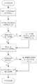
图2是含有源虚拟电感的多次低频纹波抑制流程图;Figure 2 is a flow chart of multiple low frequency ripple suppression with active virtual inductance;
图3是含有源虚拟电感的LC串联电路的模态分析图;Figure 3 is a modal analysis diagram of an LC series circuit containing a source virtual inductance;
图4是含有源虚拟电感的LC串联电路中开关驱动波形及电感电流与电容电压波形;Fig. 4 is the switch drive waveform and the inductor current and capacitor voltage waveforms in the LC series circuit containing the source virtual inductor;
图5是含有源虚拟电感的LC串联电路的控制框图;Fig. 5 is the control block diagram of the LC series circuit with source virtual inductance;
图6是含有源虚拟电感的LC串联电路各状态下输入电流及其傅里叶分析图;Fig. 6 is the input current and its Fourier analysis diagram in each state of the LC series circuit containing the source virtual inductance;
其中,Creal-与有源虚拟电感串联的电容,Lvir-有源虚拟电感,Lr-有源虚拟电感的构成电感,Cr-有源虚拟电感的构成电容,Sa-源虚拟电感的第一构成开关管,Sb-源虚拟电感的第二构成开关管,Udc-直流母线电压,ibus-直流母线电流, In是第n次电流谐波的幅值,qn是第n次电流谐波的相位。Where, Creal - capacitance in series with active virtual inductance, Lvir - active virtual inductance, Lr - constituent inductance of active virtual inductance, Cr - constituent capacitance of active virtual inductance, Sa - source virtual inductance The first constitutes a switch tube, Sb - the source virtual inductance, the second constitutes a switch tube, Udc - DC bus voltage, ibus - DC bus current, In is the amplitude of the nth current harmonic, qn is Phase of the nth current harmonic.
具体实施方式Detailed ways
以下结合附图和具体实施例,进一步阐述本发明,应理解这些实施例仅用于说明本发明而不用于限制本发明的范围,在阅读了本发明之后,本领域技术人员对本发明的各种等价形式的修改均落于本申请所附权利要求所限定的范围。The present invention will be further described below in conjunction with the accompanying drawings and specific embodiments. It should be understood that these embodiments are only used to illustrate the present invention and not to limit the scope of the present invention. Modifications of equivalent forms all fall within the scope defined by the appended claims of this application.
基于有源虚拟电感的多次低频电流纹波抑制方法,包括含有源虚拟电感串联电容的抑制纹波电路;所述抑制纹波电路由有源虚拟电感Lvri与电容Creal串联构成,连接在直流母线之间;所述抑制纹波电路利用纹波抑制支路的瞬时功率与负载产生的脉动功率大小相等,相位相反,实现指定多次纹波电流的吸收。A method for suppressing multiple low-frequency current ripples based on active virtual inductors, including a ripple suppressing circuit including an active virtual inductor series capacitor; the ripple suppressing circuit is composed of an active virtual inductor Lvri and a capacitor Creal connected in series Between the DC busbars; the ripple suppression circuit utilizes that the instantaneous power of the ripple suppression branch is equal in magnitude to the pulsating power generated by the load, and the phases are opposite, so as to achieve the absorption of specified multiple ripple currents.
参照图1,所述有源虚拟电感Lvri由互补导通的功率开关管Sa和Sb组成一桥臂,桥臂两端分别连接直流母线的正负极,桥臂中点连接电感Lr的一端,电感 Lr的另一端连接在电容Cr和电容Creal的中间,即电容Cr的负极板和电容Creal的正极板。电容Cr的正极连接直流母线的正极,电容Creal的负极连接直流母线的负极。通过控制开关Sa和Sb,使得有源虚拟电感Lvri和电容Creal的端口行为在交流上相反,即电容Cr的端口行为从容性变成了感性。Referring to FIG. 1 , the active virtual inductanceLvri is composed of complementary conductive power switch tubes Sa and Sb to form a bridge arm, the two ends of the bridge arm are respectively connected to the positive and negative poles of the DC bus, and the midpoint of the bridge arm is connected to the inductor L One end ofr and the other end of inductor Lr are connected between the capacitorCr and the capacitor Creal , that is, the negative plate of the capacitorCr and the positive plate of the capacitor Creal . The positive pole of the capacitor Cr is connected to the positive pole of the DC bus, and the negative pole of the capacitor Creal is connected to the negative pole of the DC bus. By controlling the switches Sa and Sb , the port behaviors of the active virtual inductor Lvri and the capacitor Creal are opposite in AC, that is, the port behavior of the capacitor Cr changes from capacitive to inductive.
上述的基于有源虚拟电感的多次低频电流纹波抑制方法,有源虚拟电感Lvri和电容Creal端电压uLvri与uCreal可采用电容电压单闭环控制,也可采用电容Creal电压外环、电感Lr电流内环双闭环控制。通过采集直流母线电流idc,经过计算得到有源虚拟电感或电容端口的参考电压uLvri-ref或uCreal-ref。若采用单闭环控制,则通过采集有源虚拟电感电容端口的电压uLvri或uCreal,与参考电压uLvri-ref或 uCreal-ref的差值输入电压环PI补偿器,通过SPWM控制开关Sa和Sb的通断,该方式下仅需2个传感器。若采用双闭环控制,则将上述差值输入电压外环PI补偿器,输出后作为内环电感Lr电流的参考,与反馈的电感电流iLr进行比较后,最终通过SPWM控制开关Sa和Sb的通断,该方式下仅需3个传感器。The above-mentioned method for suppressing multiple low-frequency current ripples based on active virtual inductors, the active virtual inductor Lvri and capacitor Creal terminal voltages uLvri and uCreal can be controlled by a single closed-loop capacitor voltage, or a capacitor Creal voltage can be used outside the voltage. Loop, inductor Lr current inner loop double closed-loop control. By collecting the DC bus current idc , the reference voltage uLvri-ref or uCreal-ref of the active virtual inductor or capacitor port is obtained through calculation. If single closed-loop control is adopted, the difference between the voltage uLvri or uCreal of the active virtual inductor-capacitor port and the reference voltage uLvri-ref or uCreal-ref is input to the voltage loop PI compensator, and the switch S is controlled by SPWM On/off ofa and Sb , only 2 sensors are needed in this mode. If double closed-loop control is used, the above difference is input into the voltage outer loop PI compensator, and after output, it is used as the reference for the current of the inner loop inductance Lr , compared with the feedback inductor current iLr , and finally the switchesSa and On and off of Sb , only 3 sensors are needed in this mode.
有源虚拟电感Lvri端电压uLvri和电容Creal端电压uCreal的交流分量在对特定多次谐波表现功率平衡时相位相反,且满足直流母线电压的总约束。当纹波抑制支路的瞬时功率与负载产生的脉动功率大小相等,相位相反,则可实现指定多次纹波电流的吸收。直流母线中的低频电流纹波仅在负载与纹波抑制电路间传递,减少对电源的损害。The AC components of the active virtual inductor Lvri terminal voltage uLvri and the capacitor Creal terminal voltage uCreal have opposite phases when they exhibit power balance for a specific multiple harmonics, and satisfy the overall constraint of the DC bus voltage. When the instantaneous power of the ripple suppression branch is equal in magnitude to the pulsating power generated by the load and in opposite phases, the absorption of the specified multiple ripple currents can be achieved. The low-frequency current ripple in the DC bus is only transmitted between the load and the ripple suppression circuit, reducing damage to the power supply.
本发明采用如下控制方式:The present invention adopts the following control mode:
有源虚拟电感的第一构成开关管Sa的栅极和源极间所加的驱动信号与有源虚拟电感的第二构成开关管Sb的栅极和源极间所加的驱动信号互补。The driving signal applied between the gate and the source of the switch Sa that constitutes the first active virtual inductor is complementary to the driving signal applied between the gate and the source of the switch Sb that constitutes the second active virtual inductor .
所述负电容的第一、第二构成开关管Sa、Sb的开通和关断采用正弦脉宽调制 SPWM进行控制,纹波抑制电路的开关频率综合考虑系统容量、开关管电压电流应力和系统效率优化等因素合理选取。The first and second constituent switches of the negative capacitors Sa and Sb are turned on and off using sinusoidal pulse width modulation SPWM to control, and the switching frequency of the ripple suppression circuit comprehensively considers system capacity, switch voltage and current stress and Reasonable selection of factors such as system efficiency optimization.
当直流母线中的电流包含多次低频电流纹波时,该电流可表示为When the current in the DC bus contains multiple low frequency current ripples, the current can be expressed as

利用功率匹配,当该支路的瞬时功率和负载带来的低频脉动功率大小相等,相位相反,则可实现指定次电流纹波的抑制,即Using power matching, when the instantaneous power of the branch and the low-frequency pulsating power brought by the load are equal in magnitude and opposite in phase, the specified secondary current ripple can be suppressed, that is,

求解上述微分方程,取Cr=Creal=C,得Solve the above differential equation, take Cr =Creal =C, get

上述K1,K2是微分方程求解时引入的常数,由方程解的初始状态决定。此即为多次低频电流谐波抑制的基本模式,可抑制直流电压母线中大部分的低频电流谐波,若要进一步解决纹波残留问题,则需进行下文提及的特殊模式。The above K1 , K2 are constants introduced when the differential equation is solved, and are determined by the initial state of the equation solution. This is the basic mode of multiple low-frequency current harmonic suppression, which can suppress most of the low-frequency current harmonics in the DC voltage bus. To further solve the problem of residual ripple, the special mode mentioned below is required.
在基本模式的基础上,再寻找uCr在20毫秒(单个工频周期)内的最小值 min[uCr],并记录其出现时间t1,t2,…,tk,k∈N*。最后作为PI补偿器参考信号的uLvri-ref需调制为On the basis of the basic pattern, find the minimum value min[uCr ] of uCr within 20 milliseconds (single power frequency period), and record its occurrence time t1 , t2 , ..., tk , k∈N* . Finally, uLvri-ref , which is used as the reference signal of the PI compensator, needs to be modulated as

含有源虚拟电感的多次低频纹波抑制的流程图如图2所示。在纹波抑制电路开始工作后,首先检测一个线电压周期(20ms)的母线电流,再对其进行傅里叶分析,得到各个频次纹波的幅值及其相位信息。若检测到的是首个线电压周期的母线电流,则直接计算ucr;若不是,则需与检测得到的历史周期中各个相应频次电流纹波分量的幅值与相位叠加,再进行ucr的计算。得到ucr后,若所用处理器的运算能力允许,则可进行前文所述的特殊模式下的优化;若运算能力不足(硬件配置不足或是设定吸收纹波的总次数过多等情况)时,也可牺牲一定的纹波抑制效果来满足较快的响应速度要求。并在计算完成后的下一个周期进行纹波抑制。Figure 2 shows the flow chart of multiple low frequency ripple suppression with source virtual inductance. After the ripple suppression circuit starts to work, the bus current of one line voltage period (20ms) is detected first, and then Fourier analysis is performed on it to obtain the amplitude and phase information of each frequency ripple. If the bus current of the first line voltage cycle is detected, ucr is calculated directly; if not, it needs to be superimposed with the amplitude and phase of the current ripple components of each corresponding frequency in the detected historical cycle, and then ucr is performed. calculation. After obtaining ucr , if the computing power of the processor used allows, the optimization in the special mode described above can be carried out; if the computing power is insufficient (insufficient hardware configuration or too many times of setting the total number of absorbing ripples, etc.) When , a certain ripple suppression effect can also be sacrificed to meet the requirements of faster response speed. And ripple suppression is performed in the next cycle after the calculation is completed.
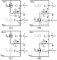
在一个开关周期中,图1所示的含有源虚拟电感的LC串联电路各有2种工作模态在3段电感电流区域,如图3(a)所示,Cr与Creal的状态具有对称性,这里以Creal为例分析,具体描述如下:In one switching cycle, the LC series circuit with source virtual inductance shown in Figure 1 has two operating modes in the three-stage inductor current region. As shown in Figure 3(a), the states of Cr and Creal have Symmetry, take Creal as an example to analyze, the specific description is as follows:
区域D2&D4:iLr在一个开关周期内变向,如图3(b),在此工作区域,开关 Sa和Sb均实现零电压开通。Regions D2 & D4 : iLr changes direction within one switching cycle, as shown in Figure 3(b), in this working region, both switchesSa and S bare turned on at zero voltage.
模态I:开关Sa导通,Sb关断。当iLr正向时,直流母线通过开关Sa给电感 Lr和电容Creal充电。电流iLr正向增大,uCreal增大,如图4(a)。当iLr反向时,电感Lr和电容Creal通过开关Sa的体二极管将能量反馈回直流母线。电流iLr反向减小,uCreal减小,如图4(c)。Mode I: switch Sa is turned on and Sb is turned off. When iLr is positive, the DC bus charges the inductor Lr and the capacitor Creal through the switch Sa . The current iLr increases positively, and uCreal increases, as shown in Figure 4(a). WheniLr is reversed, the inductor Lr and the capacitor Creal feed energy back to the DC bus through the body diode of the switch Sa. The current iLr decreases in reverse, and uCreal decreases, as shown in Figure 4(c).
模态II:开关Sa关断,Sb导通。当iLr正向时,电感Lr通过开关Sb的体二极管给电容Creal充电。电流iLr正向减小,uCreal增大,如图4(b)。当iLr反向时,电容Creal通过开关Sb给电感Lr充电。电流iLr反向增大,uCreal减小,如图4(d)。Mode II: switch Sa is turned off and Sb is turned on. When iLr is forward, the inductor Lr charges the capacitor Creal through the body diode of the switch Sb . The current iLr decreases positively and uCreal increases, as shown in Figure 4(b). When iLr is reversed, the capacitor Creal charges the inductor Lr through the switch Sb . The current iLr increases in reverse, and uCreal decreases, as shown in Figure 4(d).
区域D1:iLr>0,电压uCreal增大,如图3(c)。Region D1 : iLr >0, the voltage uCreal increases, as shown in Figure 3(c).
模态I:开关Sa导通,Sb关断。直流母线通过开关Sa给电感Lr和电容Creal充电。电流iLr正向增大,uCreal增大,如图4(a)。Mode I: switch Sa is turned on and Sb is turned off. The DC bus charges the inductor Lr and the capacitor Creal through the switch Sa . The current iLr increases positively, and uCreal increases, as shown in Figure 4(a).
模态II:开关Sa关断,Sb导通。电感Lr通过开关Sb的体二极管给电容Creal充电。电流iLr正向减小,uCreal增大,如图4(b)。Mode II: switch Sa is turned off and Sb is turned on. The inductor Lr charges the capacitor Creal through the body diode of the switch Sb . The current iLr decreases positively and uCreal increases, as shown in Figure 4(b).
区域D3:iLr<0,电压uCreal减小,如图3(d)。Region D3 : iLr <0, the voltage uCreal decreases, as shown in Fig. 3(d).
模态I:开关Sa导通,Sb关断。电感Lr和电容Creal通过开关Sa的体二极管将能量反馈给直流母线。电流iLr反向减小,uCreal减小,如图4(c)。Mode I: switch Sa is turned on and Sb is turned off. The inductor Lr and the capacitor Creal feed back the energy to the DC bus through the body diode of the switch Sa . The current iLr decreases in reverse, and uCreal decreases, as shown in Figure 4(c).
模态II:开关Sa关断,Sb导通。电容Creal通过开关Sb给电感Lr充电。电流 iLr反向增大,uCreal减小,如图4(d)。Mode II: switch Sa is turned off and Sb is turned on. The capacitor Creal charges the inductor Lr through the switch Sb . The current iLr increases in reverse, and uCreal decreases, as shown in Figure 4(d).
有源虚拟电感Lvri和电容Creal端电压uLvri与uCreal可采用电容电压单闭环控制,也可采用电容Creal电压外环、电感Lr电流内环双闭环控制。通过采集直流母线电流idc,经过计算得到有源虚拟电感或电容端口的参考电压uLvri-ref或uCreal-ref。若采用单闭环控制,则通过采集有源虚拟电感或电容端口的电压uLvri或uCreal,与参考电压uLvri-ref或uCreal-ref的差值输入电压环PI补偿器,通过SPWM控制开关Sa和Sb的通断,该方式下仅需2个传感器。若采用双闭环控制,则将上述差值输入电压外环PI补偿器,输出后作为内环电感Lr电流的参考,与反馈的电感电流 iLr进行比较后,最终通过SPWM控制开关Sa和Sb的通断,该方式下仅需3个传感器。如图5所示。Active virtual inductor Lvri and capacitor Creal terminal voltages uLvri and uCreal can be controlled by capacitor voltage single closed-loop control, or by capacitor Creal voltage outer loop and inductor Lr current inner loop double closed-loop control. By collecting the DC bus current idc , the reference voltage uLvri-ref or uCreal-ref of the active virtual inductor or capacitor port is obtained through calculation. If single closed-loop control is adopted, the difference between the voltage uLvri or uCreal of the active virtual inductor or capacitor port and the reference voltage uLvri-ref or uCreal-ref is input to the voltage loop PI compensator, and the switch is controlled by SPWM On/off of Sa and Sb , only 2 sensors are needed in this mode. If double closed-loop control is used, the above difference is input into the voltage outer loop PI compensator, and after output, it is used as the reference for the current of the inner loop inductance Lr , compared with the feedback inductor current iLr , and finally the switchesSa and On and off of Sb , only 3 sensors are needed in this mode. As shown in Figure 5.
由上述控制方式可知,含有源虚拟电感的支路中的电容取值大小与直流母线电压与脉动功率大小有关,即如下式所示,其中Phar为产生电流纹波的脉动功率。It can be seen from the above control method that the value of the capacitance in the branch containing the source virtual inductance is related to the DC bus voltage and the pulsating power, as shown in the following formula, where Phar is the pulsating power that generates the current ripple.

根据GB/T 14549 93的纹波指标规定,为减少Lr与Cr、Creal谐振次纹波对系统造成的影响,要使Lr与Cr、Creal谐振频率大于电路工作频率的21倍。设工作频率为fw(即逆变器输出电压频率),则电感Lr的最大值为According to the ripple index of GB/T 14549 93, in order to reduce the influence ofLr , Cr , Creal resonant sub-ripple on the system, the resonant frequency of Lr ,Cr , Creal should be greater than 21% of the circuit operating frequency. times. Assuming that the operating frequency is fw (that is, the inverter output voltage frequency), the maximum value of the inductance Lr is

根据上述参数选取,进行电路仿真。有源虚拟电感电路设计参数如表所示,直流母线电压Ui为250V,电容Cr和Creal为150μF,电感Lr为120μH,开关频率fs为10kHz。According to the above parameters, the circuit simulation is carried out. The design parameters of the active virtual inductor circuit are shown in the table. The DC bus voltage Ui is 250V, the capacitors Cr and Creal are 150 μF, the inductance Lr is 120 μH, and the switching frequency fs is 10 kHz.

仿真利用2个单相逆变器引入低频谐波,输出电压均为125V,输出滤波电感均为2.5mH,滤波电容均为1μF,开关频率均为10kHz,负载均为50Ω。交流输出电压频率为50Hz和75Hz,分别引入100Hz(二倍频)和150Hz(三倍频) 电流谐波。The simulation uses two single-phase inverters to introduce low-frequency harmonics, the output voltage is 125V, the output filter inductance is 2.5mH, the filter capacitor is 1μF, the switching frequency is 10kHz, and the load is 50Ω. The AC output voltage frequency is 50Hz and 75Hz, and 100Hz (double frequency) and 150Hz (triple frequency) current harmonics are introduced respectively.
图6(a)是含有源虚拟电感电路未激活时,电路中各电信号的仿真结果。在 2个输出频率不同的逆变器同时工作的情况下,直流母线电流含有大量低频纹波。Figure 6(a) is the simulation result of each electrical signal in the circuit when the circuit containing the active virtual inductance is not activated. In the case of two inverters with different output frequencies working at the same time, the DC bus current contains a lot of low frequency ripple.
图6(b)是含有源虚拟电感电路在基础模式下工作时,电路中各电信号的仿真结果。在2个输出频率不同的逆变器同时工作的情况下,直流母线电流中存在的低频纹波被大幅吸收,但每经过20毫秒仍会出现小幅电流震荡。Figure 6(b) is the simulation result of each electrical signal in the circuit when the circuit with active virtual inductance works in the basic mode. When two inverters with different output frequencies work at the same time, the low-frequency ripple in the DC bus current is largely absorbed, but there is still a small current oscillation every 20 milliseconds.
图6(c)是含有源虚拟电感电路在特殊模式下工作时,电路中各电信号的仿真结果。在2个输出频率不同的逆变器同时工作的情况下,直流母线电流中存在的低频纹波被大幅吸收,且在整个工作周期内无明显震荡。Figure 6(c) is the simulation result of each electrical signal in the circuit when the circuit with active virtual inductance works in a special mode. When two inverters with different output frequencies work at the same time, the low-frequency ripple in the DC bus current is largely absorbed, and there is no obvious oscillation during the entire working cycle.
图6(d)是上述三种情况下,直流母线电流进行傅里叶分析后的结果。在含有源虚拟电感结构的纹波抑制电路未工作时,该情况下电流中的二次谐波电流占46.9%,三次谐波电流占47.9%。在含有源虚拟电感结构的纹波抑制电路在基础模式下工作时,该情况下电流中的二次谐波电流占4.2%,三次谐波电流占4.8%,但在前21次频率范围内产生了额外的电流谐波。在含有源虚拟电感结构的纹波抑制电路在特殊模式下工作时,该情况下电流中的二次谐波电流占1.2%,三次谐波电流占2.4%,且在前21次频率范围内几乎不产生额外的电流谐波。Figure 6(d) is the result of Fourier analysis of the DC bus current in the above three cases. When the ripple suppression circuit with the source virtual inductance structure does not work, the second harmonic current in the current accounts for 46.9%, and the third harmonic current accounts for 47.9%. When the ripple suppression circuit with the active virtual inductance structure works in the fundamental mode, the second harmonic current in this case accounts for 4.2%, and the third harmonic current accounts for 4.8%, but the first 21 harmonic currents are generated in the frequency range of the first 21 times. additional current harmonics. When the ripple suppression circuit with the active virtual inductance structure works in the special mode, the second harmonic current in this case accounts for 1.2%, the third harmonic current accounts for 2.4%, and almost in the first 21 frequency range No additional current harmonics are generated.
上述仅为本发明的一个具体实施方式,但本发明的设计构思并不局限于此,凡利用此构思对本发明进行非实质性的改动,均应属于侵犯本发明保护范围的行为。The above is only a specific embodiment of the present invention, but the design concept of the present invention is not limited to this, and any non-substantial modification of the present invention by using this concept shall be regarded as an act infringing the protection scope of the present invention.
Claims (6)
Priority Applications (1)
| Application Number | Priority Date | Filing Date | Title |
|---|---|---|---|
| CN202011426249.0ACN112838577B (en) | 2020-12-07 | 2020-12-07 | Multiple low frequency current ripple suppression method based on active virtual inductor |
Applications Claiming Priority (1)
| Application Number | Priority Date | Filing Date | Title |
|---|---|---|---|
| CN202011426249.0ACN112838577B (en) | 2020-12-07 | 2020-12-07 | Multiple low frequency current ripple suppression method based on active virtual inductor |
Publications (2)
| Publication Number | Publication Date |
|---|---|
| CN112838577A CN112838577A (en) | 2021-05-25 |
| CN112838577Btrue CN112838577B (en) | 2022-07-01 |
Family
ID=75923487
Family Applications (1)
| Application Number | Title | Priority Date | Filing Date |
|---|---|---|---|
| CN202011426249.0AActiveCN112838577B (en) | 2020-12-07 | 2020-12-07 | Multiple low frequency current ripple suppression method based on active virtual inductor |
Country Status (1)
| Country | Link |
|---|---|
| CN (1) | CN112838577B (en) |
Families Citing this family (3)
| Publication number | Priority date | Publication date | Assignee | Title |
|---|---|---|---|---|
| CN114142453B (en)* | 2021-11-18 | 2024-02-13 | 厦门大学 | Secondary current ripple suppression method based on active large capacitance |
| CN115425635B (en)* | 2022-08-19 | 2024-07-23 | 厦门大学 | A low-frequency harmonic suppression circuit and method based on asymmetric parameters of fractional-order capacitors |
| CN117977913B (en)* | 2024-01-30 | 2024-08-23 | 广东工业大学 | Virtual variable inductor and control circuit and control method thereof |
Family Cites Families (4)
| Publication number | Priority date | Publication date | Assignee | Title |
|---|---|---|---|---|
| US7518886B1 (en)* | 2005-02-18 | 2009-04-14 | Virginia Tech Intellectual Properties, Inc. | Multiphase soft switched DC/DC converter and active control technique for fuel cell ripple current elimination |
| CN104795981B (en)* | 2015-04-24 | 2017-06-16 | 山东大学 | The mixing microgrid reversible transducer current ripples active suppressing method that direct current is incorporated into the power networks |
| EP3393034A1 (en)* | 2017-04-21 | 2018-10-24 | GE Energy Power Conversion Technology Limited | Controlling a back-to-back three-level converter with midpoint voltage ripple compensation |
| CN109039038B (en)* | 2018-07-04 | 2021-06-01 | 天津大学 | Secondary ripple suppression method of capacitive energy storage type single-phase rectifier based on virtual impedance |
- 2020
- 2020-12-07CNCN202011426249.0Apatent/CN112838577B/enactiveActive
Also Published As
| Publication number | Publication date |
|---|---|
| CN112838577A (en) | 2021-05-25 |
Similar Documents
| Publication | Publication Date | Title |
|---|---|---|
| CN110380626B (en) | High-power-density single-phase cascade H-bridge rectifier, control method and control system | |
| CN112838577B (en) | Multiple low frequency current ripple suppression method based on active virtual inductor | |
| CN109039038B (en) | Secondary ripple suppression method of capacitive energy storage type single-phase rectifier based on virtual impedance | |
| CN103078522B (en) | A kind of control method of capacitor charging AC-DC series resonance matrix converter control device | |
| CN112202322B (en) | A Method of Suppressing Secondary Ripple Current by Equivalent Zero Impedance Based on Active Negative Capacitor | |
| CN109980978A (en) | A kind of converter and its modulator approach | |
| CN103516248B (en) | Based on the LLCL filtering combining inverter of single current loop control | |
| CN104811069B (en) | A kind of forecast Control Algorithm of modular multilevel inverter | |
| WO2021208274A1 (en) | Power factor adjustment architecture applicable to single-phase/three-phase power grid, and control method therefor | |
| CN113726199B (en) | Low-output ripple boost rectifier and control method thereof | |
| CN115051565A (en) | Bidirectional half-bridge direct-current converter grid-connected inverter and ripple wave control method | |
| CN115425635A (en) | An asymmetrical parameter low-frequency harmonic suppression circuit and method based on fractional-order capacitance | |
| CN208971375U (en) | A DC side active filter for eliminating secondary resonance of train DC bus | |
| CN110649829A (en) | Single-phase three-level power factor correction rectifier based on asymmetric four-port | |
| CN115693632B (en) | A control method for a DC microgrid power oscillation suppression device | |
| CN110535364B (en) | Improved modulation method of double Buck inverters based on auxiliary power supply | |
| CN102969880B (en) | Second ripple removing circuit of single-phase voltage-type convertor | |
| CN106849103A (en) | Transformerless type single-phase dynamic voltage compensator based on HVDC Modulation | |
| CN106655862A (en) | Ripple suppressing non-isolated inverter and control method thereof | |
| CN209072370U (en) | A kind of single phase bidirectional AC-DC charge-discharge circuit | |
| CN117155089A (en) | Input ripple suppression method for three-phase voltage type inverter under nonlinear load | |
| CN205901304U (en) | Mixed type APF topology circuit who contains flying capacitor structure | |
| CN104836465B (en) | LC serial-type three-phase PWM rectifier current iterative learning control method | |
| CN108539756A (en) | Single-phase reactive power compensator based on Buck types three-level AC-AC-AC converter | |
| CN109842317B (en) | Differential converter based on Boost and Buck-Boost circuits and application thereof |
Legal Events
| Date | Code | Title | Description |
|---|---|---|---|
| PB01 | Publication | ||
| PB01 | Publication | ||
| SE01 | Entry into force of request for substantive examination | ||
| SE01 | Entry into force of request for substantive examination | ||
| GR01 | Patent grant | ||
| GR01 | Patent grant |