CN112833786B - A cabin position and attitude measurement and alignment system, control method and application - Google Patents
A cabin position and attitude measurement and alignment system, control method and applicationDownload PDFInfo
- Publication number
- CN112833786B CN112833786BCN202110005821.4ACN202110005821ACN112833786BCN 112833786 BCN112833786 BCN 112833786BCN 202110005821 ACN202110005821 ACN 202110005821ACN 112833786 BCN112833786 BCN 112833786B
- Authority
- CN
- China
- Prior art keywords
- cabin
- measurement
- axis
- pose
- coordinate system
- Prior art date
- Legal status (The legal status is an assumption and is not a legal conclusion. Google has not performed a legal analysis and makes no representation as to the accuracy of the status listed.)
- Active
Links
- 238000000034methodMethods0.000titleclaimsabstractdescription135
- 238000005259measurementMethods0.000titleclaimsabstractdescription118
- 230000009466transformationEffects0.000claimsabstractdescription42
- 238000004088simulationMethods0.000claimsabstractdescription13
- 238000004422calculation algorithmMethods0.000claimsabstractdescription7
- 238000004519manufacturing processMethods0.000claimsdescription25
- 239000011159matrix materialSubstances0.000claimsdescription21
- 230000008569processEffects0.000claimsdescription17
- 230000033001locomotionEffects0.000claimsdescription11
- 230000003287optical effectEffects0.000claimsdescription11
- 238000005096rolling processMethods0.000claimsdescription7
- 238000005457optimizationMethods0.000claimsdescription6
- 238000013519translationMethods0.000claimsdescription6
- 238000004364calculation methodMethods0.000claimsdescription4
- 238000006243chemical reactionMethods0.000claimsdescription4
- 238000003384imaging methodMethods0.000claimsdescription4
- 238000012545processingMethods0.000claimsdescription4
- 238000007726management methodMethods0.000claimsdescription3
- 210000001503jointAnatomy0.000claims3
- 230000001276controlling effectEffects0.000claims2
- 238000010276constructionMethods0.000claims1
- 230000001105regulatory effectEffects0.000claims1
- 230000001131transforming effectEffects0.000claims1
- 238000003032molecular dockingMethods0.000abstractdescription16
- 238000005516engineering processMethods0.000abstractdescription5
- 238000010586diagramMethods0.000description10
- 230000000007visual effectEffects0.000description8
- 238000013461designMethods0.000description5
- 238000009826distributionMethods0.000description5
- 238000000691measurement methodMethods0.000description5
- 239000000523sampleSubstances0.000description5
- 238000011160researchMethods0.000description4
- 230000007547defectEffects0.000description3
- 239000000047productSubstances0.000description3
- 108010066057cabin-1Proteins0.000description2
- 238000004891communicationMethods0.000description2
- 238000012937correctionMethods0.000description2
- 230000001419dependent effectEffects0.000description2
- 238000011161developmentMethods0.000description2
- 238000009434installationMethods0.000description2
- 230000007246mechanismEffects0.000description2
- 239000007921spraySubstances0.000description2
- 238000005507sprayingMethods0.000description2
- 238000000342Monte Carlo simulationMethods0.000description1
- 238000004458analytical methodMethods0.000description1
- 201000010099diseaseDiseases0.000description1
- 208000037265diseases, disorders, signs and symptomsDiseases0.000description1
- 230000000694effectsEffects0.000description1
- 230000002708enhancing effectEffects0.000description1
- 238000002474experimental methodMethods0.000description1
- 238000012986modificationMethods0.000description1
- 230000004048modificationEffects0.000description1
- 230000008092positive effectEffects0.000description1
- 238000012827research and developmentMethods0.000description1
- 239000000126substanceSubstances0.000description1
- 239000013589supplementSubstances0.000description1
Images


Classifications
- G—PHYSICS
- G01—MEASURING; TESTING
- G01B—MEASURING LENGTH, THICKNESS OR SIMILAR LINEAR DIMENSIONS; MEASURING ANGLES; MEASURING AREAS; MEASURING IRREGULARITIES OF SURFACES OR CONTOURS
- G01B11/00—Measuring arrangements characterised by the use of optical techniques
- G01B11/002—Measuring arrangements characterised by the use of optical techniques for measuring two or more coordinates
- G—PHYSICS
- G01—MEASURING; TESTING
- G01B—MEASURING LENGTH, THICKNESS OR SIMILAR LINEAR DIMENSIONS; MEASURING ANGLES; MEASURING AREAS; MEASURING IRREGULARITIES OF SURFACES OR CONTOURS
- G01B11/00—Measuring arrangements characterised by the use of optical techniques
- G01B11/24—Measuring arrangements characterised by the use of optical techniques for measuring contours or curvatures
- G01B11/2433—Measuring arrangements characterised by the use of optical techniques for measuring contours or curvatures for measuring outlines by shadow casting
Landscapes
- Physics & Mathematics (AREA)
- General Physics & Mathematics (AREA)
- Length Measuring Devices By Optical Means (AREA)
Abstract
Translated fromChinese
Description
Translated fromChinese技术领域technical field
本应用技术属于舱段的对接技术领域,尤其涉及一种舱段位姿测量及对准系统、控制方法及应用。The application technology belongs to the technical field of cabin docking, and in particular relates to a cabin pose measurement and alignment system, a control method and an application.
背景技术Background technique
目前:作为国家工业的重要组成部分,航空航天制造业的生产能力代表了一个国家综合国力和生产力的强弱。同时,该领域在很大程度上也受到了智能制造概念的影响。从目前航空航天产品的发展状况来说,传统的生产模式已经难以满足愈发提高的性能和质量要求,因此基于机器人和各种智能设备的新型生产线将会成为航天器制造业的改革发展方向。At present: As an important part of the national industry, the production capacity of the aerospace manufacturing industry represents the strength of a country's comprehensive national strength and productivity. At the same time, the field has also been largely influenced by the concept of smart manufacturing. From the perspective of the current development of aerospace products, the traditional production mode has been difficult to meet the increasing performance and quality requirements, so the new production line based on robots and various smart devices will become the reform and development direction of the spacecraft manufacturing industry.
其中作为航天器生产的关键环节,航天器总装的质量将直接决定产品的最终性能,因此,总装环节的升级在航天系统升级改造过程中的地位极其重要。同时,由于涉及的部件比部装环节来说质量更大,精度要求不变甚至更高,且产品型号多变,因此对所涉及的装配系统在效率、质量以及柔性等方面都有着相对严格的要求。然而,对于航天器自动化总装,我国目前研究则相对滞后,相关的生产、制造部门需要的往往正是这些智能化的工装设备。究其原因,在于智能化设备的研发需要高昂的人力、技术、财力乃至实际操作经验的投入,该代价往往是科研院所、高校等研究单位难以承受的。且不同于以往,智能化生产设备的设计与制造往往涉及多领域的交叉合作,各领域的关键问题、疑难杂症都会在智能设备的制造中得以体现,这也使得智能化工装的设计无法像以往一样,由生产部门像传统工装一样独立承担其设计与制造任务。特别是对于航空航天总装来说,由于所涉及的零件尺寸、重量较大,已远超现有机械手等执行机构的承受范围,因此依靠选型、组装来设计生产线将难以解决很多关键的技术问题。As a key link in the production of spacecraft, the quality of the final assembly of the spacecraft will directly determine the final performance of the product. Therefore, the upgrade of the final assembly link is extremely important in the process of upgrading the aerospace system. At the same time, since the components involved are of greater quality than the assembly process, the accuracy requirements remain the same or even higher, and the product models are changeable, so there are relatively strict requirements on the efficiency, quality, and flexibility of the assembly system involved. Require. However, for the automatic assembly of spacecraft, my country's current research is relatively lagging behind, and the relevant production and manufacturing departments often need these intelligent tooling equipment. The reason is that the research and development of intelligent equipment requires high investment in manpower, technology, financial resources and even practical operation experience, which is often unbearable for research institutes, universities and other research units. And different from the past, the design and manufacture of intelligent production equipment often involves cross-cooperation in multiple fields. Key issues and intractable diseases in various fields will be reflected in the manufacture of intelligent equipment, which also makes the design of intelligent chemical equipment impossible. As in the past, the production department independently undertakes its design and manufacturing tasks like traditional tooling. Especially for aerospace assembly, because the size and weight of the parts involved are far beyond the tolerance range of existing manipulators and other actuators, it will be difficult to solve many key technical problems by relying on selection and assembly to design the production line .
综上所述,现有技术的研究目标是:In summary, the research objectives of the prior art are:
(1)非接触:接触式测量需要反复移动探针取得被测物表面点的位置,进而拟合零件的位姿,一方面,需要通过机械装置完成探针的移动,这样将挤占其他设备的安装空间,导致设备臃肿;另一方面,接触式测量设备的探针需要和零件表面接触,一些特殊情况中,该方法使用将受到限制,如被测物温度较高,表面柔软等。目前的CMM虽然可以取得较高的精度(0.001mm级),但其庞大的驱动结构使其仅可以作为单独的测量仪器使用,无法被集成在装配生产线中。(1) Non-contact: Contact measurement needs to repeatedly move the probe to obtain the position of the surface point of the measured object, and then fit the pose of the part. On the one hand, it is necessary to complete the movement of the probe through a mechanical device, which will occupy the space of other equipment. The installation space leads to bloated equipment; on the other hand, the probe of the contact measurement equipment needs to be in contact with the surface of the part. In some special cases, the use of this method will be limited, such as the temperature of the measured object is high and the surface is soft. Although the current CMM can achieve high precision (0.001mm level), its huge drive structure makes it only available as a separate measuring instrument and cannot be integrated in the assembly line.
(2)无靶标:在被测物表面喷涂或安放测量靶标虽然便于测量仪器得到被测物的位置,但对于整个装配流程来说,需要增加额外的人力成本以完成该过程。例如激光跟踪仪、双目视觉近景测量技术等需要在被测物表面喷涂测量靶标或安置相应的测量靶标后,才能完成测量。(2) No target: Spraying or placing measurement targets on the surface of the measured object is convenient for the measuring instrument to obtain the position of the measured object, but for the entire assembly process, additional labor costs are required to complete the process. For example, laser tracker, binocular vision close-range measurement technology, etc. need to spray the measurement target on the surface of the measured object or install the corresponding measurement target before the measurement can be completed.
(3)大范围:舱段类零件往往具有较大的长径比,因此测量设备的视场范围要大。对于单一的视觉测量手段来说,随着视场范围的增大,精度将会减小,无法满足舱段的对接要求。(3) Large range: Cabin parts often have a large aspect ratio, so the field of view of the measuring equipment should be large. For a single visual measurement method, as the field of view increases, the accuracy will decrease, which cannot meet the docking requirements of the cabin.
(4)自动化。对于自动化装配系统来说,不应因引入人工而带来额外的工作量,因此一些需要人工干预的测量手段显然是不能胜任该工作要求的。例如关节式测量臂需要人力操作以完成对零件位姿的测量,一些场合中需要人工移动激光跟踪仪的靶球完成位姿的拟合等。(4) Automation. For automated assembly systems, the introduction of labor should not bring additional workload, so some measurement methods that require manual intervention are obviously not up to the job requirements. For example, the articulated measuring arm needs human operation to complete the measurement of the part's pose, and in some occasions, it is necessary to manually move the target ball of the laser tracker to complete the pose fitting.
(5)稳健性。实际工程环境往往为非结构化环境,存在各种干扰,因此要求测量系统具有较强的抗干扰能力。对于目前市面上常见的不依赖靶标的精密视觉测量系统来说,通常需要纯净的背景和结构化的光照,因此无法满足工程环境下的测量需求。(5) Robustness. The actual engineering environment is often an unstructured environment with various interferences, so the measurement system is required to have strong anti-interference ability. For the precision vision measurement system that is not dependent on the target that is currently on the market, it usually requires a pure background and structured lighting, so it cannot meet the measurement requirements in the engineering environment.
通过上述分析,现有技术存在的问题及缺陷为:Through the above analysis, the problems and defects in the prior art are:
(1)现有接触式测量通过机械装置完成探针的移动,挤占其他设备的安装空间,导致设备臃肿;接触式测量设备的探针需要和零件表面接触,一些特殊情况中,该方法使用将受到限制。(1) The existing contact measurement uses mechanical devices to complete the movement of the probe, which occupies the installation space of other equipment, resulting in bloated equipment; the probe of the contact measurement equipment needs to be in contact with the surface of the part. In some special cases, this method uses the restricted.
(2)现有在被测物表面喷涂或安放测量靶标对于整个装配流程需要增加额外的人力成本以完成该过程。(2) Currently, spraying or placing measurement targets on the surface of the measured object requires additional labor costs for the entire assembly process to complete the process.
(3)对于单一的视觉测量手段来说,随着视场范围的增大,精度将会减小,无法满足舱段的对接要求。(3) For a single visual measurement method, as the field of view increases, the accuracy will decrease, which cannot meet the docking requirements of the cabin.
(4)现有实际工程环境往往为非结构化环境,存在各种干扰,因此要求测量系统具有较强的抗干扰能力;目前市面上常见的不依赖靶标的精密视觉测量系统来说,无法满足工程环境下的测量需求。(4) The existing actual engineering environment is often an unstructured environment with various interferences, so the measurement system is required to have a strong anti-interference ability; the precision vision measurement system that is not dependent on the target currently on the market cannot meet the requirements Measurement requirements in engineering environments.
解决以上问题及缺陷的难度为:首先因为是运动单一视觉测量的手段,所以视场范围增大是,精度的减小会达不到舱段的对接要求,针对这一问题现阶段只能通过人工来调整相机和目标的距离使其达到测量要求;针对于目前系统抗干扰能力的不足,在不使用依赖靶标的精密测量系统情况下,目前市场存在的测量系统无法满足工程环境下的测量要求。The difficulty in solving the above problems and defects is as follows: firstly, because it is a single visual measurement method for movement, the increase in the field of view will reduce the accuracy and will not meet the docking requirements of the cabin. To solve this problem at this stage, only through Manually adjust the distance between the camera and the target to meet the measurement requirements; in view of the lack of anti-interference ability of the current system, without using a precision measurement system that relies on the target, the current measurement system in the market cannot meet the measurement requirements in the engineering environment .
解决以上问题及缺陷的意义为:如果没有使用人力来喷涂或者安放靶标和使用相同的就能够准确识别被测物体的一些特征,并且能够准确的拟合物体。这对于算法来说是一个巨大的突破,对于视觉识别物体来说也是有了一个巨大的飞跃。如果测量系统拥有很高的抗干扰能力,那么对于系统来说所需要的靶标也就会减少,针对于目前市场上的无靶标的测量系统的精度不够的问题来说,是一个补充,而且拥有很高的抗干扰能力,对于此套系统在市场的应用前景也十分广阔。The significance of solving the above problems and defects is: if you do not use manpower to spray or place targets and use the same ones, you can accurately identify some features of the measured object and accurately fit the object. This is a huge breakthrough for algorithms, and a huge leap for visual recognition of objects. If the measurement system has a high anti-interference ability, then the number of targets required for the system will also be reduced, which is a supplement to the problem of insufficient accuracy of the target-free measurement system currently on the market, and has High anti-interference ability, the application prospect of this system in the market is also very broad.
发明内容Contents of the invention
针对现有技术存在的问题,本技术提供了一种舱段位姿测量及对准系统、控制方法及应用。Aiming at the problems existing in the prior art, the present technology provides a cabin pose measurement and alignment system, a control method and an application.
本技术方法是这样实现的,一种舱段位姿测量及对准控制方法,所述舱段位姿测量及对准控制方法包括:This technical method is achieved in this way, a cabin pose measurement and alignment control method, the cabin pose measurement and alignment control method includes:
通过直线扫描的方法扫描舱段的表面通过使用轴线的拟合和母线拟合的综合方法,结合轴线法沿Y轴测量精度较高和母线法沿X轴测量精度较高的优点,避免单一轴线法或母线法分别沿Y轴和X轴的测量误差,并且通过蒙特卡洛数值模拟方法来对轴线和母线进行大量的数值模拟;The surface of the cabin is scanned by the method of straight line scanning. By using the comprehensive method of axis fitting and busbar fitting, combined with the advantages of high measurement accuracy along the Y axis of the axis method and high measurement accuracy of the busbar method along the X axis, a single axis is avoided. The measurement errors along the Y-axis and the X-axis of the method or the busbar method respectively, and a large number of numerical simulations are performed on the axis and the busbar through the Monte Carlo numerical simulation method;
根据原理样机实验量化分析了分布式相机配准过程中的误差,提出了一种基于刚体变换矩阵Htrans、缩放修正矩阵Hscale以及几何变换矩阵HGeo的舱段配准模型。在其基础之上提出了基于物理特征的相机组配准方法。其中,对同一端面进行拍照的相机组而言,采用了一种标准筒形件并通过其上的配准孔对相机组进行配准。对于拍摄相对端面上配合特征的相机对来说,本发明设计了一种专用配准装置,用以对相机对进行配准。最后,通过原理样机对本发明方法进行验证,证明了该方法的正确性。According to the principle prototype experiment, the errors in the registration process of distributed cameras were quantitatively analyzed, and a cabin registration model based on rigid body transformation matrix Htrans , scaling correction matrix Hscale and geometric transformation matrix HGeo was proposed. Based on it, a camera group registration method based on physical features is proposed. Wherein, for the camera group that takes pictures on the same end surface, a standard cylindrical member is used to register the camera group through the registration holes on it. For the camera pair that photographs matching features on opposite end surfaces, the present invention designs a special registration device for registering the camera pair. Finally, the method of the present invention is verified by a prototype machine, which proves the correctness of the method.
进一步,所述舱段位姿测量及对准控制方法通过结构光三角法获取的点云包含有深度信息,用三维扫描传感器都将沿着扫描方向获取的光带叠加,得到被测面的亮度图,冀以获取端面特征的精确三维位置信息。Further, the point cloud obtained by the structured light triangulation method in the cabin pose measurement and alignment control method contains depth information, and the three-dimensional scanning sensor will superimpose the light bands obtained along the scanning direction to obtain the brightness map of the measured surface , in order to obtain the precise three-dimensional position information of the end surface features.
进一步,所述舱段位姿测量及对准控制方法测量结合RANSAC对M-估计改进,在进行圆心识别的同时对轮廓有效性判定;同时,针对截面圆弧轮廓的圆心估计问题,基于工程实际对圆拟合和椭圆拟合的精度进行讨论和改进。Further, the cabin pose measurement and alignment control method measurement is combined with RANSAC to improve the M-estimation, and the validity of the contour is judged while the center of the circle is identified; at the same time, for the problem of circle center estimation of the section arc contour, based on engineering practice, the The accuracy of circle fitting and ellipse fitting is discussed and improved.
进一步,所述舱段位姿测量及对准控制方法基于分布式相机的法兰角度的测量,采用相同数目,分布环状布置的两组工业相机倾斜向内对两个待对接的筒形件A和B的端面分别进行拍照,构成分布式单目系统;其中,单目标定目的在于准确获取每个销/孔在对应相机各自实际坐标系的位置;相机组配准目的在于以获取所有相机到全局坐标系中的配准矩阵H,进行坐标转化和计算。Further, the cabin pose measurement and alignment control method is based on the measurement of the flange angle of the distributed cameras, using the same number, two groups of industrial cameras arranged in a ring are inclined inward to the two cylindrical parts A to be docked and the end faces of B to form a distributed monocular system; the purpose of single target positioning is to accurately obtain the position of each pin/hole in the actual coordinate system of the corresponding camera; the purpose of camera group registration is to obtain all cameras to The registration matrix H in the global coordinate system is used for coordinate conversion and calculation.
进一步,所述舱段位姿测量及对准控制方法通过单目相机对销-孔特征进行倾斜拍照,再根据相机的成像原理对直接获得的图像进行矫正和重投影,以准确获销-孔特征在空间中的真实位置。Further, the cabin pose measurement and alignment control method uses a monocular camera to obliquely take pictures of the pin-hole features, and then corrects and re-projects the directly obtained images according to the imaging principle of the camera, so as to accurately obtain the pin-hole features real position in space.
进一步,所述舱段位姿测量及对准控制方法采用多个相机从不同的方向倾斜拍摄;通过同端面相机组的重合变换和几何变换和一种标定方法用以对同一端面进行拍摄的相机组进行配准;通过一定的算法寻求使上述两轨迹重合的变换关系,根据两轨迹之间确定的几何关系进一步对其进行变换,得到两个轨迹在空间中的真实位姿。Further, the cabin pose measurement and alignment control method adopts multiple cameras to shoot obliquely from different directions; through coincidence transformation and geometric transformation of the camera group on the same end face and a calibration method, the camera group used to shoot the same end face Carry out registration; through a certain algorithm, seek the transformation relationship that makes the above two trajectories coincide, and further transform them according to the geometric relationship determined between the two trajectories, and obtain the real pose of the two trajectories in space.
进一步,所述舱段位姿测量及对准控制方法的姿态测量,上位机可控制的激光轮廓扫描仪沿给定方向对舱段的侧面进行扫描,并从获取的点云数据中求解舱段的轴线位姿;同时,分布式相机组对两个待对接的端面进行拍照以捕获两舱段端面上的配合特征,并计算舱段法兰的转角误差;对于控制部分发送数据进行调整:控制系统对装配过程进行控制,包括处理测量系统采集的数据并计算位姿误差,根据位姿误差计算各执行元件的调整量,规划调姿路径;与工厂生产管理系统的通讯,对生产环节的智能化控制以及提供人机接口。Further, in the pose measurement of the cabin and the attitude measurement of the alignment control method, the laser profile scanner controlled by the host computer scans the side of the cabin along a given direction, and solves the position of the cabin from the obtained point cloud data. At the same time, the distributed camera group takes pictures of the two end faces to be docked to capture the matching features on the end faces of the two cabins, and calculates the corner error of the cabin flange; adjusts the data sent by the control part: the control system adjusts the assembly The process is controlled, including processing the data collected by the measurement system and calculating the pose error, calculating the adjustment amount of each actuator according to the pose error, and planning the attitude adjustment path; communication with the factory production management system, intelligent control of the production process, and Provides a human-machine interface.
进一步,所述舱段位姿测量及对准控制方法的姿态调整包括;Further, the attitude adjustment of the cabin pose measurement and alignment control method includes;
1)六自由度平台归零,六条支腿长度构成的矢量为
2)在舱段一上建立坐标系2,通过控制软件中自行开发的位姿变换程序,得到其原点坐标和姿态角共6个参数,记为t1=(x2,y2,z2,α2,β2,γ2)T;2) Establish the coordinate
坐标系2和操作平台坐标系1的位姿关系变换矩阵为:

3)在舱段2的平台上的对接口上建立坐标系3;通过位姿变换程序,得到其原点坐标和姿态角共6个参数,记为t3=(x3,y3,z3,α3,β3,γ3)T;3) Establish the coordinate system 3 on the docking port on the platform of the
4)将坐标系2,3的信息即t2,t3的值送入上位机的控制软件,对准机软件中的运动学解算程序计算出坐标系2在调整后要到达的位姿t'2=(x3,y3,z3-hz,α3,β3,γ3)T;为了实现对准目标中的高度方差值(h1-h′1)2+(h2-h′2)2最小,hz的选取采用如下的最优化方法确定:4) Send the information of coordinate

式中,h1,h2分别为舱段1和2相对于地面上的高度;δh12为舱段1和2的法兰端面的圆心的高度差;In the formula, h1 and h2 are the heights of
由t′2和前述的坐标系1,2的关系,得操作平台坐标系1在调整后要到达的原点位置坐标为:o'1=(x2-x3,y2-y3,z2-z3)T,姿态旋转变换阵为:
在六自由度平台建造时,已经确定了其第i个球铰在坐标系1中的位置向量pi,并且已知第i个胡克铰在大地坐标系中的位置向量pb,以上,计算调整后第i个支腿的长度为:When the six-degree-of-freedom platform is built, the position vector pi of the i-th spherical hinge in the coordinate system 1 has been determined, and the position vector pb of the i-th Hookee hinge in the earth coordinate system is known. Above, calculate the adjustment The length of the i-th outrigger is:

运行六自由度平台的控制软件,使每条支腿在伺服系统的驱动下,长度量增加:
5)为了实现对准目标中的角度方差值(α1-α′1)2+(β1-β′1)2最小,在保持舱段1高度和轴线方向不变的前提下,调整舱段1使其绕轴线旋转角度γ7;γ7的值由控制软件中的优化程序模块采用如下的最优化方法确定:5) In order to achieve the minimum angle variance value (α1 -α′1 )2 +(β1 -β′1 )2 in the alignment target, under the premise of keeping the height and axis direction of cabin section 1 unchanged, adjust Cabin 1 makes it rotate around the axis by an angle of γ7 ; the value of γ7 is determined by the optimization program module in the control software using the following optimization method:

式中,α1β1分别为以过舱段1对接口、舱段2对接口法兰端面的圆心垂直于各自轴线的夹角理论值;对准机控制软件根据指令参数γ7,调整六自由度平台6条支腿的长度,实现涡轮泵绕其轴线旋转角度γ7;In the formula, α1 β1 are the theoretical values of the included angles between the center of the flange end faces of the pairing interface of cabin section 1 and
6)测量并检验两舱段法兰端面的圆心的高度和角度要求是否满足对接要求;若满足,则对准过程结束。否则,再进行一次调姿运动,即重复上述第4)和5)步。6) Measure and inspect whether the height and angle of the center of the flange end faces of the two cabin sections meet the docking requirements; if they meet, the alignment process ends. Otherwise, perform another posture adjustment exercise, that is, repeat steps 4) and 5) above.
本发明的另一目的在于提供一种实施所述舱段位姿测量及对准控制方法的舱段位姿测量及对准系统,所述舱段位姿测量及对准装置包括:Another object of the present invention is to provide a cabin pose measurement and alignment system implementing the cabin pose measurement and alignment control method, and the cabin pose measurement and alignment device includes:
测量模块,用于对于两个舱段的拍照和测量;The measurement module is used for photographing and measuring the two compartments;
对接模块,安置在调整对准装置上,每个舱段的自由度相当于有留个自由度,用于进行平移反转和滚动运动。The docking module is placed on the adjustment and alignment device, and the degree of freedom of each cabin is equivalent to one degree of freedom, which is used for translation, inversion and rolling motion.
所述舱段位姿测量及对准系统设置有光学平台,光学平台上装有扫描测量模块、照相测量模块;The cabin pose measurement and alignment system is provided with an optical platform, and a scanning measurement module and a photogrammetry module are installed on the optical platform;
照相测量模块由两台工业照相机分别安装在支撑架上用于照相和测量两段舱体;两个舱体两个舱段分别由两个六自由度机器人平台支撑;标定架安装在平台上和两个相机的中间;The photogrammetry module consists of two industrial cameras installed on the support frame to take pictures and measure the two cabins; the two cabins and the two cabins are respectively supported by two six-degree-of-freedom robot platforms; the calibration frame is installed on the platform and between the two cameras;
扫描测量模块直接安装在光学平台上;The scanning measurement module is directly installed on the optical table;
视觉测量模块和标定块通过安装架安装在两个舱段之间用于对于两个舱段的拍照和测量;舱段安置在调整对准装置上,每个舱段的自由度相当于有留个自由度,进行平移反转和滚动运动。The visual measurement module and the calibration block are installed between the two compartments through the mounting bracket for taking pictures and measuring the two compartments; the compartments are placed on the adjustment and alignment device, and the degree of freedom of each compartment is equivalent to the remaining degrees of freedom for translational inversion and rolling motions.
本发明的另一目的在于提供一种智能制造控制终端,所述智能制造控制终端用于实现所述的舱段位姿测量及对准控制方法。Another object of the present invention is to provide an intelligent manufacturing control terminal, which is used to implement the cabin pose measurement and alignment control method.
结合上述的所有技术方案,本发明所具备的优点及积极效果为:本发明的舱段安置在调整对准装置上,每个舱段的自由度相当于有六个自由度,能够进行平移反转和滚动运动;通过直线扫描的方法扫描舱段的表面通过使用轴线的拟合和母线拟合的综合方法,结合轴线法沿Y轴测量精度较高和母线法沿X轴测量精度较高的优点,避免单一轴线法或母线法分别沿Y轴和X轴的测量误差,并且通过蒙特卡洛数值模拟方法来对轴线和母线进行大量的数值模拟,在满足测量精度误差的条件下,综合法的标准差值更小,如表1、表2、表3所示;Combining all the above-mentioned technical solutions, the advantages and positive effects of the present invention are: the compartments of the present invention are placed on the adjustment and alignment device, and the degrees of freedom of each compartment are equivalent to six degrees of freedom, which can be translated and reversed. Turning and rolling motion; scan the surface of the cabin section by linear scanning method by using the comprehensive method of axis fitting and generatrix fitting, combined with the axis method with higher measurement accuracy along the Y axis and the generatrix method with higher measurement accuracy along the X axis Advantages: avoid the measurement error of the single axis method or the busbar method along the Y axis and the X axis respectively, and use the Monte Carlo numerical simulation method to perform a large number of numerical simulations on the axis and busbar. Under the condition of meeting the measurement accuracy error, the comprehensive method The standard deviation of is smaller, as shown in Table 1, Table 2, and Table 3;
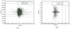
本发明通过结构光三角法获取的点云包含有较高精度的深度信息,但在垂直于深度的方向上,其信息是离散的。因此,用三维扫描传感器都可以将沿着扫描方向获取的光带叠加,得到被测面的亮度图,冀以获取端面特征的精确三维位置信息,也就是能够精确的确定端面的圆心坐标。如图9各种方法得到圆心的点云分布所示。The point cloud acquired by the structured light triangulation method in the present invention contains relatively high-precision depth information, but the information is discrete in the direction perpendicular to the depth. Therefore, the light bands obtained along the scanning direction can be superimposed with the three-dimensional scanning sensor to obtain the brightness map of the measured surface, in order to obtain accurate three-dimensional position information of the end surface features, that is, to accurately determine the center coordinates of the end surface. Figure 9 shows the point cloud distribution of the center of the circle obtained by various methods.
本发明在测量的稳健性增强方面,考虑到激光扫描数据具有较大的冗余性,结合RANSAC的思路对M-估计进行改进,使其在进行圆心识别的同时可以对轮廓有效性进行判定,剔除干扰较多的轮廓。同时,针对截面圆弧轮廓的圆心估计问题,基于工程实际对圆拟合和椭圆拟合的精度进行讨论和改进。在特别追求调姿精度的位姿测量-调整流程中,可采用此种方法以降低测量效率的代价进一步提高精度。如图10和表4为前后对比数据。In terms of enhancing the robustness of the measurement, the present invention takes into account the large redundancy of the laser scanning data, and improves the M-estimation in combination with the idea of RANSAC, so that it can judge the validity of the outline while identifying the center of the circle. Eliminate the contours with more interference. At the same time, aiming at the problem of estimating the center of the section arc profile, the accuracy of circle fitting and ellipse fitting is discussed and improved based on engineering practice. In the pose measurement-adjustment process that particularly pursues the accuracy of attitude adjustment, this method can be used to further improve the accuracy at the cost of reducing measurement efficiency. Figure 10 and Table 4 are the comparison data before and after.
本发明单目标定目的在于准确获取每个销/孔在对应相机各自实际坐标系的位置;相机组配准目的在于以获取所有相机到全局坐标系中的配准矩阵H。从而能够进行简单的坐标转化和计算;通过单目相机对销-孔特征进行倾斜拍照,再根据相机的成像原理对直接获得的图像进行矫正和重投影,以准确获销-孔特征在空间中的真实位置;采用多个相机从不同的方向倾斜拍摄。这样,每个相机视场范围内仅有一个特征,因此可以取得较高的精度。The purpose of single target positioning in the present invention is to accurately obtain the position of each pin/hole in the respective actual coordinate system of the corresponding camera; the purpose of camera group registration is to obtain the registration matrix H of all cameras to the global coordinate system. In this way, simple coordinate conversion and calculation can be carried out; the pin-hole feature is obliquely photographed through the monocular camera, and then the directly obtained image is corrected and re-projected according to the imaging principle of the camera, so as to accurately obtain the pin-hole feature in space real location; multiple cameras tilted from different directions. This way, there is only one feature in each camera's field of view, so higher accuracy can be achieved.
综上所述,本发明在扫描测量上使用的轴线和母线综合方法,并且使用蒙特卡洛数值模拟对于得到的数值进行了模拟实验,因此对于求出舱段的轴线的位姿起到了提高精确测量的效果;并且在后续中使用的改进M-估计,使其在进行圆心识别的同时可以对轮廓有效性进行判定,剔除干扰较多的轮廓。对圆拟合和椭圆拟合的精度进行讨论和改进,进一步的提高了测量的稳定性和精确性;在确定法兰的转角和销孔的问题上提出了一种基于分布式相机倾斜拍照的筒形件法兰转角位姿测量方法。该方法可以不依赖测量靶标自动、高效地对舱段对接过程中法兰的转角位姿进行精密测量,从而驱动伺服装置闭环地完成转角位姿的调整以进行准确地对接;根据原理样机实验量化分析了分布式相机配准过程中的误差,提出了一种基于刚体变换矩阵、缩放修正矩阵,以及几何变换矩阵的舱段配准模型。在其基础之上提出了基于物理特征的相机组配准方法;提出的方法相对基于激光跟踪仪的方法,直接针对返回的图像特征进行配准,摆脱了对昂贵的激光跟踪仪的依赖。相对于基于反射镜的方法,这种方法不需要复杂的光学系统,因此在实际生产中更容易实施。In summary, the present invention uses the comprehensive method of axis and busbar in scanning measurement, and uses Monte Carlo numerical simulation to carry out simulation experiments on the obtained values, so it can improve the accuracy of calculating the position and orientation of the axis of the cabin section. The effect of the measurement; and the improved M-estimation used in the follow-up, so that it can judge the validity of the contour while identifying the center of the circle, and eliminate the contour with more interference. Discuss and improve the accuracy of circle fitting and ellipse fitting, which further improves the stability and accuracy of measurement; on the problem of determining the corner of the flange and the pin hole, a method based on distributed camera oblique photography is proposed. A method for measuring the angle and pose of the flange of a cylindrical part. This method can automatically and efficiently measure the angle and pose of the flange during the cabin docking process without relying on the measurement target, so as to drive the servo device to complete the adjustment of the angle and pose in a closed loop for accurate docking; The error in the process of distributed camera registration is analyzed, and a cabin registration model based on rigid body transformation matrix, scaling correction matrix and geometric transformation matrix is proposed. On the basis of it, a camera group registration method based on physical features is proposed; compared with the laser tracker-based method, the proposed method directly registers the returned image features, and gets rid of the dependence on the expensive laser tracker. Compared with the mirror-based method, this method does not require complex optical systems, so it is easier to implement in actual production.
表1蒙特卡洛仿真得到各方法估计椭圆圆心的分布参数(mm)Table 1 The distribution parameters (mm) of the ellipse center estimated by each method obtained by Monte Carlo simulation

表2各轴线求解方法对轴线位姿参数的数值仿真结果Table 2 Numerical simulation results of axis pose parameters by solution methods for each axis

表3绝对精度测量数据Table 3 Absolute accuracy measurement data


注:方法A:综合法方法B:轴线法方法C:LTS的测量方法Note: Method A: Comprehensive method Method B: Axis method Method C: LTS measurement method
表4测量位姿参数对比Table 4 Comparison of measured pose parameters

附图说明Description of drawings
为了更清楚地说明本申请实施例的技术方案,下面将对本申请实施例中所需要使用的附图做简单的介绍,显而易见地,下面所描述的附图仅仅是本申请的一些实施例,对于本领域普通技术人员来讲,在不付出创造性劳动的前提下还可以根据这些附图获得其他的附图。In order to more clearly illustrate the technical solutions of the embodiments of the present application, the following will briefly introduce the accompanying drawings required in the embodiments of the present application. Obviously, the accompanying drawings described below are only some embodiments of the present application. Those of ordinary skill in the art can also obtain other drawings based on these drawings without making creative efforts.
图1是本发明实施例提供的舱段位姿测量及对准系统的结构示意图;Fig. 1 is a structural schematic diagram of a cabin pose measurement and alignment system provided by an embodiment of the present invention;
图2是本发明实施例提供的舱段位姿测量及对准控制方法的流程图。Fig. 2 is a flow chart of the cabin pose measurement and alignment control method provided by the embodiment of the present invention.
图3是本发明实施例提供的测量部分结构示意图;Fig. 3 is a schematic structural diagram of the measurement part provided by the embodiment of the present invention;
图4是本发明实施例提供的对接部分结构示意图;Fig. 4 is a schematic structural diagram of the docking part provided by the embodiment of the present invention;
图5是本发明实施例提供的调整机构的六自由度并联机构示意图;Fig. 5 is a schematic diagram of a six-degree-of-freedom parallel mechanism of an adjustment mechanism provided by an embodiment of the present invention;
图6是本发明实施例提供的激光扫描模块结构示意图;Fig. 6 is a schematic structural diagram of a laser scanning module provided by an embodiment of the present invention;
图7是本发明实施例提供的激光轮廓传感器测量原理示意图示意图;Fig. 7 is a schematic diagram of the measurement principle of the laser profile sensor provided by the embodiment of the present invention;
图8是本发明实施例提供的采用辅助配准装置的相机配准方法示意图;Fig. 8 is a schematic diagram of a camera registration method using an auxiliary registration device provided by an embodiment of the present invention;
图中:1、光学平台;2、扫描测量模块;3、标定架;4、视觉测量模块;5、舱段模块;6、扫描传感器;7、步进电机;8、编码器;9、支撑柱;10、拖链;11、直线模组;12、测量模块;13、对接模块。In the figure: 1. Optical platform; 2. Scanning measurement module; 3. Calibration frame; 4. Visual measurement module; 5. Cabin module; 6. Scanning sensor; 7. Stepper motor; 8. Encoder; 9. Support column; 10, drag chain; 11, linear module; 12, measurement module; 13, docking module.
图9本发明实施例提供的各种方法得到圆心的点云分布图。Fig. 9 is a point cloud distribution diagram of the circle center obtained by various methods provided by the embodiments of the present invention.
图中(a)轴线法和综合法得到的圆心分布图,(b)母线法和综合法得到的圆心分布图。In the figure (a) the distribution diagram of the center of the circle obtained by the axis method and the comprehensive method, (b) the distribution diagram of the center of the circle obtained by the busbar method and the comprehensive method.
图10本发明实施例提供的圆拟合估计圆心和椭圆拟合估计圆心的对比。Fig. 10 is a comparison between the circle fitting estimated circle center and the ellipse fitting estimated circle center provided by the embodiment of the present invention.
具体实施方式Detailed ways
为了使本发明的目的、技术方案及优点更加清楚明白,以下结合实施例,对本发明进行进一步详细说明。应当理解,此处所描述的具体实施例仅仅用以解释本发明,并不用于限定本发明。In order to make the object, technical solution and advantages of the present invention more clear, the present invention will be further described in detail below in conjunction with the examples. It should be understood that the specific embodiments described here are only used to explain the present invention, not to limit the present invention.
针对现有技术存在的问题,本发明提供了一种舱段位姿测量及对准系统、控制方法及应用,下面结合附图对本发明作详细的描述。Aiming at the problems existing in the prior art, the present invention provides a cabin pose measurement and alignment system, control method and application. The present invention will be described in detail below with reference to the accompanying drawings.
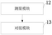
如图1所示,本发明提供的舱段位姿测量及对准系统包括:测量模块12、对接模块13。As shown in FIG. 1 , the cabin pose measurement and alignment system provided by the present invention includes: a
测量模块12,用于对于两个舱段的拍照和测量。The
对接模块13,安置在调整对准装置上,每个舱段的自由度相当于有留个自由度,用于进行平移反转和滚动运动。The
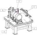
本发明主要有光学平台支撑整个结构,光学平台上装有扫描测量模块、照相测量模块,照相测量模块由两台工业照相机分别安装在支撑架上用于照相和测量两段舱体;两个舱体两个舱段分别由两个六自由度机器人平台支撑,所以每个平台都有六个自由度,能够完成相应的平移,翻滚和旋转;标定架安装在平台上和两个相机的中间。扫描测量部分直接安装在光学平台上;视觉测量模块和标定块通过安装架安装在两个舱段之间用于对于两个舱段的拍照和测量;舱段安置在调整对准装置上,每个舱段的自由度相当于有留个自由度,能够进行平移反转和滚动运动。The present invention mainly has an optical platform to support the whole structure, and the optical platform is equipped with a scanning measurement module and a photographic measurement module, and the photographic measurement module is respectively installed on the supporting frame by two industrial cameras for taking pictures and measuring two sections of cabins; two cabins The two cabins are respectively supported by two six-degree-of-freedom robot platforms, so each platform has six degrees of freedom and can complete corresponding translation, rollover and rotation; the calibration frame is installed on the platform and in the middle of the two cameras. The scanning measurement part is directly installed on the optical platform; the visual measurement module and the calibration block are installed between the two compartments through the mounting bracket for taking pictures and measuring the two compartments; the compartments are placed on the adjustment and alignment device, and each The degree of freedom of each cabin section is equivalent to having 4 degrees of freedom, which can perform translation, inversion and rolling motion.
如图2所示,本发明提供的舱段位姿测量及对准控制方法包括:As shown in Figure 2, the cabin pose measurement and alignment control method provided by the present invention includes:
S101:通过直线扫描的方法扫描舱段的表面通过使用轴线的拟合和母线拟合的综合方法,结合轴线法沿Y轴测量精度较高和母线法沿X轴测量精度较高的优点,避免单一轴线法或母线法分别沿Y轴和X轴的测量误差,并且通过蒙特卡洛数值模拟方法来对轴线和母线进行大量的数值模拟;S101: Scan the surface of the cabin section by linear scanning method. By using the comprehensive method of axis fitting and busbar fitting, combined with the advantages of the axis method with higher measurement accuracy along the Y-axis and the busbar method with higher measurement accuracy along the X-axis, avoid Measurement errors along the Y-axis and X-axis with the single-axis method or the busbar method, and a large number of numerical simulations of the axes and busbars are carried out through the Monte Carlo numerical simulation method;
S102:通过同端面相机组的重合变换和几何变换和一种标定方法用以对同一端面进行拍摄的相机组进行配准。其基本思路为通过一定的算法寻求使上述两轨迹重合的变换关系,根据两轨迹之间确定的几何关系进一步对其进行变换,得到两个轨迹在空间中的真实位姿。S102: Registering the camera groups photographed on the same end face through coincidence transformation and geometric transformation of the same end face camera group and a calibration method. The basic idea is to use a certain algorithm to find the transformation relationship that makes the above two trajectories coincide, and further transform them according to the geometric relationship determined between the two trajectories, so as to obtain the real pose of the two trajectories in space.
本发明的提供的舱段位姿测量及对准控制方法还包括:通过结构光三角法获取的点云包含有较高精度的深度信息,但在垂直于深度的方向上,其信息是离散的。因此,用三维扫描传感器都可以将沿着扫描方向获取的光带叠加,得到被测面的亮度图,冀以获取端面特征的精确三维位置信息,也就是能够精确的确定端面的圆心坐标。The cabin pose measurement and alignment control method provided by the present invention further includes: the point cloud obtained by the structured light triangulation method contains relatively high-precision depth information, but the information is discrete in the direction perpendicular to the depth. Therefore, the light bands obtained along the scanning direction can be superimposed with the three-dimensional scanning sensor to obtain the brightness map of the measured surface, in order to obtain accurate three-dimensional position information of the end surface features, that is, to accurately determine the center coordinates of the end surface.
本发明的提供的舱段位姿测量及对准控制方法还包括:在测量的稳健性增强方面,考虑到激光扫描数据具有较大的冗余性,结合RANSAC的思路对M-估计进行改进,使其在进行圆心识别的同时可以对轮廓有效性进行判定,剔除干扰较多的轮廓。同时,针对截面圆弧轮廓的圆心估计问题,基于工程实际对圆拟合和椭圆拟合的精度进行讨论和改进。在特别追求调姿精度的位姿测量-调整流程中,可采用此种方法以降低测量效率的代价进一步提高精度。The cabin pose measurement and alignment control method provided by the present invention also includes: in terms of robustness enhancement of the measurement, considering the large redundancy of the laser scanning data, the M-estimation is improved in combination with the idea of RANSAC, so that It can judge the validity of the outline while identifying the center of the circle, and remove the outline with more interference. At the same time, aiming at the problem of estimating the center of the section arc profile, the accuracy of circle fitting and ellipse fitting is discussed and improved based on engineering practice. In the pose measurement-adjustment process that particularly pursues the accuracy of attitude adjustment, this method can be used to further improve the accuracy at the cost of reducing measurement efficiency.
本发明的提供的舱段位姿测量及对准控制方法还包括:基于分布式相机的法兰角度的测量,该方法采用相同数目,分布环状布置的两组工业相机倾斜向内对两个待对接的筒形件A和B的端面分别进行拍照,构成分布式单目系统。其中,单目标定目的在于准确获取每个销/孔在对应相机各自实际坐标系的位置;相机组配准目的在于以获取所有相机到全局坐标系中的配准矩阵H。从而能够进行简单的坐标转化和计算。The cabin pose measurement and alignment control method provided by the present invention also includes: the measurement of the flange angle based on the distributed cameras. The end faces of the docked cylindrical parts A and B are photographed separately to form a distributed monocular system. Among them, the purpose of single target positioning is to accurately obtain the position of each pin/hole in the actual coordinate system of the corresponding camera; the purpose of camera group registration is to obtain the registration matrix H of all cameras to the global coordinate system. Thus, simple coordinate conversion and calculation can be performed.
本发明的提供的舱段位姿测量及对准控制方法还包括:通过单目相机对销-孔特征进行倾斜拍照,再根据相机的成像原理对直接获得的图像进行矫正和重投影,以准确获销-孔特征在空间中的真实位置。The cabin pose measurement and alignment control method provided by the present invention also includes: using a monocular camera to obliquely take pictures of the pin-hole features, and then correcting and reprojecting the directly obtained images according to the imaging principle of the camera, so as to accurately obtain The true location of the pin-hole feature in space.
本发明的提供的舱段位姿测量及对准控制方法还包括:采用多个相机从不同的方向倾斜拍摄。这样,每个相机视场范围内仅有一个特征,因此可以取得较高的精度。并且通过同端面相机组的重合变换和几何变换和一种标定方法用以对同一端面进行拍摄的相机组进行配准。其基本思路为通过一定的算法寻求使上述两轨迹重合的变换关系,根据两轨迹之间确定的几何关系进一步对其进行变换,得到两个轨迹在空间中的真实位姿。The cabin pose measurement and alignment control method provided by the present invention further includes: adopting multiple cameras to shoot obliquely from different directions. This way, there is only one feature in each camera's field of view, so higher accuracy can be achieved. And through the coincidence transformation and geometric transformation of the same end face camera group and a calibration method, it is used to register the camera groups shooting on the same end face. The basic idea is to use a certain algorithm to find the transformation relationship that makes the above two trajectories coincide, and further transform them according to the geometric relationship determined between the two trajectories, so as to obtain the real pose of the two trajectories in space.
下面结合附图对本发明的技术方案作进一步的描述。The technical scheme of the present invention will be further described below in conjunction with the accompanying drawings.
本发明提供的舱段位姿测量及对准控制方法包括以下步骤:The cabin pose measurement and alignment control method provided by the present invention comprises the following steps:
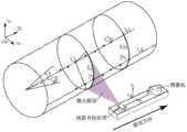
第一步,姿态测量,测量系统主要包含激光轮廓扫描仪、工业相机以及相应的数据处理算法。其中,上位机可控制图6的激光轮廓扫描仪沿给定方向对舱段的侧面进行扫描,并从获取的点云数据中求解舱段的轴线位姿。同时,分布式相机组对两个待对接的端面进行拍照以捕获两舱段端面上的配合特征,并计算舱段法兰的转角误差。接下来就是对于控制部分发送数据进行调整:控制系统包括硬件和软件两部分,其中硬件包括控制计算机,伺服控制器、驱动器以及光电编码器等,上位机软件包括工业组态软件,传感器数据处理软件以及伺服控制软件等。控制系统主要负责两方面的工作,一方面是对装配过程进行控制,包括处理测量系统采集的数据并计算位姿误差,根据位姿误差计算各执行元件的调整量,规划调姿路径等;另一方面是与工厂生产管理系统的通讯,对生产环节的智能化控制以及提供人机接口等工作。The first step is attitude measurement. The measurement system mainly includes laser profile scanners, industrial cameras and corresponding data processing algorithms. Among them, the host computer can control the laser profile scanner in Figure 6 to scan the side of the cabin along a given direction, and calculate the axis pose of the cabin from the acquired point cloud data. At the same time, the distributed camera group takes pictures of the two end faces to be docked to capture the matching features on the end faces of the two cabins, and calculates the corner error of the cabin flange. The next step is to adjust the data sent by the control part: the control system includes hardware and software. The hardware includes the control computer, servo controller, driver, and photoelectric encoder. The host computer software includes industrial configuration software and sensor data processing software. And servo control software, etc. The control system is mainly responsible for two aspects of work, one is to control the assembly process, including processing the data collected by the measurement system and calculating the pose error, calculating the adjustment amount of each actuator according to the pose error, and planning the attitude adjustment path, etc.; On the one hand, it is the communication with the factory production management system, the intelligent control of the production process and the provision of man-machine interface.
第二步,姿态调整;The second step is posture adjustment;
1)六自由度平台归零,六条支腿长度构成的矢量为
2)在舱段一上建立坐标系2如图4,通过控制软件中自行开发的位姿变换程序,得到其原点坐标和姿态角共6个参数,记为t1=(x2,y2,z2,α2,β2,γ2)T;2) Establish a coordinate
坐标系2和操作平台坐标系1的位姿关系变换矩阵为:

3)在舱段2的平台上的对接口上建立坐标系3。通过位姿变换程序,得到其原点坐标和姿态角共6个参数,记为t3=(x3,y3,z3,α3,β3,γ3)T;3) Establish a coordinate system 3 on the docking port on the platform of the
4)将坐标系2,3的信息即t2,t3的值送入上位机的控制软件,对准机软件中的运动学解算程序计算出坐标系2在调整后要到达的位姿t′2=(x3,y3,z3-hz,α3,β3,γ3)T;4) Send the information of coordinate
为了实现对准目标中的高度方差值(h1-h′1)2+(h2-h′2)2最小,hz的选取采用如下的最优化方法确定:In order to achieve the minimum height variance value (h1 -h′1 )2 +(h2 -h′2 )2 in the alignment target, the selection of hz is determined by the following optimization method:

式中,h1,h2分别为舱段1和2相对于地面上的高度;δh12为舱段1和2的法兰端面的圆心的高度差(可测出)。In the formula, h1 and h2 are the heights of
由t′2和前述的坐标系1,2的关系,可得操作平台坐标系1在调整后要到达的原点位置坐标为:o′1=(x2-x3,y2-y3,z2-z3)T,姿态旋转变换阵为:
在六自由度平台建造时,已经确定了其第i个球铰(连接第i个支腿与操作平台)在坐标系1中的位置向量pi,并且已知第i个胡克铰(连接第i个支腿与竖直桁架)在大地坐标系中的位置向量pb,以上i=1,2,...,6。因此可计算调整后第i个支腿的长度为:When the six-degree-of-freedom platform is built, the position vector pi of its i-th spherical hinge (connecting the i-th outrigger and the operating platform) in the coordinate system 1 has been determined, and the i-th Hookee hinge (connecting the i-th legs and vertical trusses) in the geodetic coordinate system of the position vector pb , above i=1, 2,...,6. Therefore, the length of the i-th outrigger after adjustment can be calculated as:

运行六自由度平台的控制软件,使每条支腿在伺服系统的驱动下,长度量增加:
5)为了实现对准目标中的角度方差值(α1-α′1)2+(β1-β′1)2最小,还需在保持舱段1高度和轴线方向不变的前提下,调整舱段1使其绕轴线旋转角度γ7;5) In order to achieve the minimum angle variance value (α1 -α′1 )2 +(β1 -β′1 )2 in the alignment target, it is also necessary to keep the cabin 1 height and axis direction unchanged , adjust cabin section 1 to make it rotate around the axis by angle γ7 ;
γ7的值由控制软件中的优化程序模块采用如下的最优化方法确定:The value of γ7 is determined by the optimization program module in the control software using the following optimization method:

式中,α1β1分别为以过舱段1对接口、舱段2对接口法兰端面的圆心垂直于各自轴线的夹角理论值。In the formula, α1 and β1 are the theoretical values of the included angles between the center of the flange end faces of the abutment joints of cabin section 1 and
对准机控制软件根据指令参数γ7,调整六自由度平台6条支腿的长度,实现涡轮泵绕其轴线旋转角度γ7,其详细调整原理与4)中相同,此处不再重复叙述。至此,完成了两工件的绕轴线的角度要求。The alignment machine control software adjusts the length of the six legs of the six-degree-of-freedom platform according to the command parameter γ7 to realize the rotation angle γ7 of the turbo pump around its axis. The detailed adjustment principle is the same as in 4), and will not be repeated here . So far, the angle requirements of the two workpieces around the axis have been completed.
6)测量并检验两舱段法兰端面的圆心的高度和角度要求是否满足对接要求;若满足,则对准过程结束。否则,再进行一次调姿运动,即重复上述第4)和5)步。6) Measure and inspect whether the height and angle of the center of the flange end faces of the two cabin sections meet the docking requirements; if they meet, the alignment process ends. Otherwise, perform another posture adjustment exercise, that is, repeat steps 4) and 5) above.
本发明在测量上使用靶标来配准相机完成测量工作,而且在测量设备的视觉厂范围上更大,在自动化上的程度上更加高,免去了在一些人为干预下产生的误差,同时具有更高的稳定性,在满足需求的前提下极大的简化了操作和节约了制造成本。The present invention uses the target to register the camera to complete the measurement work, and has a larger visual scope of the measurement equipment, and a higher degree of automation, which avoids errors generated under some human intervention, and has the advantages of Higher stability greatly simplifies the operation and saves the manufacturing cost under the premise of meeting the demand.
在本发明的描述中,除非另有说明,“多个”的含义是两个或两个以上;术语“上”、“下”、“左”、“右”、“内”、“外”、“前端”、“后端”、“头部”、“尾部”等指示的方位或位置关系为基于附图所示的方位或位置关系,仅是为了便于描述本发明和简化描述,而不是指示或暗示所指的装置或元件必须具有特定的方位、以特定的方位构造和操作,因此不能理解为对本发明的限制。此外,术语“第一”、“第二”、“第三”等仅用于描述目的,而不能理解为指示或暗示相对重要性。In the description of the present invention, unless otherwise stated, the meaning of "plurality" is two or more; the terms "upper", "lower", "left", "right", "inner", "outer" , "front end", "rear end", "head", "tail", etc. indicate the orientation or positional relationship based on the orientation or positional relationship shown in the drawings, and are only for the convenience of describing the present invention and simplifying the description, rather than Nothing indicating or implying that a referenced device or element must have a particular orientation, be constructed, and operate in a particular orientation should therefore not be construed as limiting the invention. In addition, the terms "first", "second", "third", etc. are used for descriptive purposes only and should not be construed as indicating or implying relative importance.
以上所述,仅为本发明的具体实施方式,但本发明的保护范围并不局限于此,任何熟悉本技术领域的技术人员在本发明揭露的技术范围内,凡在本发明的精神和原则之内所作的任何修改、等同替换和改进等,都应涵盖在本发明的保护范围之内。The above is only a specific embodiment of the present invention, but the scope of protection of the present invention is not limited thereto. Anyone familiar with the technical field within the technical scope disclosed in the present invention, whoever is within the spirit and principles of the present invention Any modifications, equivalent replacements and improvements made within shall fall within the protection scope of the present invention.
Claims (5)


Priority Applications (1)
| Application Number | Priority Date | Filing Date | Title |
|---|---|---|---|
| CN202110005821.4ACN112833786B (en) | 2021-01-05 | 2021-01-05 | A cabin position and attitude measurement and alignment system, control method and application |
Applications Claiming Priority (1)
| Application Number | Priority Date | Filing Date | Title |
|---|---|---|---|
| CN202110005821.4ACN112833786B (en) | 2021-01-05 | 2021-01-05 | A cabin position and attitude measurement and alignment system, control method and application |
Publications (2)
| Publication Number | Publication Date |
|---|---|
| CN112833786A CN112833786A (en) | 2021-05-25 |
| CN112833786Btrue CN112833786B (en) | 2023-02-03 |
Family
ID=75927595
Family Applications (1)
| Application Number | Title | Priority Date | Filing Date |
|---|---|---|---|
| CN202110005821.4AActiveCN112833786B (en) | 2021-01-05 | 2021-01-05 | A cabin position and attitude measurement and alignment system, control method and application |
Country Status (1)
| Country | Link |
|---|---|
| CN (1) | CN112833786B (en) |
Families Citing this family (15)
| Publication number | Priority date | Publication date | Assignee | Title |
|---|---|---|---|---|
| CN114379742B (en)* | 2021-12-13 | 2025-01-07 | 中国科学院沈阳自动化研究所 | A device and method for detecting and docking a large underwater robot in sections |
| CN114766097B (en)* | 2022-01-27 | 2024-02-06 | 武汉领普科技有限公司 | Position changing device and human body sensor, processing method and control system thereof |
| CN114963894A (en)* | 2022-05-31 | 2022-08-30 | 大连四达高技术发展有限公司 | Full bomb assembly intelligent perception system |
| CN115061148B (en)* | 2022-06-21 | 2024-07-09 | 中国人民解放军63921部队 | Rocket vertical take-off section track measurement method and system |
| FR3137860A1 (en)* | 2022-07-16 | 2024-01-19 | Institut De Recherche Technologique Jules Verne | Automated docking process for two parts including servo control with profilometers |
| CN115675784B (en)* | 2022-10-28 | 2023-05-26 | 天津大学 | A docking system and docking method for ship general section based on digital measurement field |
| KR102755757B1 (en)* | 2022-11-25 | 2025-01-21 | 한국항공우주연구원 | Diagnostic system of the projectile |
| CN116245944B (en)* | 2022-12-29 | 2024-01-05 | 南京航空航天大学 | Cabin automatic docking method and system based on measured data |
| CN116652929A (en)* | 2023-01-30 | 2023-08-29 | 北京思灵机器人科技有限责任公司 | Missile cabin assembly system |
| CN115993079A (en)* | 2023-02-15 | 2023-04-21 | 北京理工大学 | Bullet cabin interfacing apparatus |
| CN116140987A (en)* | 2023-04-17 | 2023-05-23 | 广东施泰德测控与自动化设备有限公司 | Visual quick docking device and docking method for axle test board |
| CN116573159A (en)* | 2023-05-16 | 2023-08-11 | 哈尔滨工业大学 | Simulation test device for automatic docking of cabin section of simple aircraft |
| CN116772739B (en)* | 2023-06-20 | 2024-01-23 | 北京控制工程研究所 | A deformation monitoring method and device for large-sized structures in a vacuum environment |
| CN116740183B (en)* | 2023-08-15 | 2023-11-07 | 浙江大学 | Double-view cabin pose adjusting method |
| CN119238094A (en)* | 2024-11-08 | 2025-01-03 | 上海航天设备制造总厂有限公司 | Fixture and method for adjusting the position of the lower fulcrum of the docking mechanism |
Family Cites Families (6)
| Publication number | Priority date | Publication date | Assignee | Title |
|---|---|---|---|---|
| US7614154B2 (en)* | 2007-10-26 | 2009-11-10 | The Boeing Company | System and method for locating components of a structure |
| CN104390612B (en)* | 2014-07-08 | 2017-03-08 | 西安电子科技大学 | Six-degree-of-freedom parallel robot benchmark pose scaling method for Stewart platform configuration |
| CN105091746B (en)* | 2015-05-19 | 2017-10-13 | 北京星航机电装备有限公司 | Calibration method of space coordinate system applied to ground docking of spacecraft cabin |
| CN108917723B (en)* | 2018-05-14 | 2020-08-07 | 西北工业大学 | An online pose measurement system and method for cylindrical cabin docking |
| CN108534679B (en)* | 2018-05-14 | 2019-08-13 | 西安电子科技大学 | A kind of cylindrical member axis pose without target self-operated measuring unit and method |
| CN110146038B (en)* | 2019-06-08 | 2020-09-08 | 西安电子科技大学 | Distributed monocular camera laser measuring device and method for assembly corner of cylindrical part |
- 2021
- 2021-01-05CNCN202110005821.4Apatent/CN112833786B/enactiveActive
Also Published As
| Publication number | Publication date |
|---|---|
| CN112833786A (en) | 2021-05-25 |
Similar Documents
| Publication | Publication Date | Title |
|---|---|---|
| CN112833786B (en) | A cabin position and attitude measurement and alignment system, control method and application | |
| US9043146B2 (en) | Systems and methods for tracking location of movable target object | |
| CN110757504B (en) | Positioning error compensation method of high-precision movable robot | |
| WO2023193362A1 (en) | Hybrid robot and three-dimensional vision based large-scale structural part automatic welding system and method | |
| CN113681559B (en) | Line laser scanning robot hand-eye calibration method based on standard cylinder | |
| CN109764805B (en) | Mechanical arm positioning device and method based on laser scanning | |
| CN107738254A (en) | The conversion scaling method and system of a kind of mechanical arm coordinate system | |
| WO2020024178A1 (en) | Hand-eye calibration method and system, and computer storage medium | |
| CN105015800B (en) | Automatic assembly system for spacecraft cabin on ground | |
| CN109373894B (en) | An automatic positioning method for the connection intersection point hole system of aircraft components based on distributed monocular vision | |
| CN113043332B (en) | Arm shape measuring system and method of rope-driven flexible robot | |
| CN112959364B (en) | Industrial robot assembly error compensation system and method | |
| CN112381881A (en) | Monocular vision-based automatic butt joint method for large rigid body component | |
| CN115179323B (en) | Machine terminal posture measurement device and precision improvement method based on telecentric vision constraint | |
| CN114001651A (en) | Large-scale long and thin cylinder type component pose in-situ measurement method based on binocular vision measurement and prior detection data | |
| CN108788550A (en) | Detection device, the control method and device that areola welding bead is detected using detection device | |
| CN112971984B (en) | Coordinate registration method based on integrated surgical robot | |
| CN116295089A (en) | An automatic scanning detection system and method for an engine profile | |
| CN119468976A (en) | A method and system for autonomous three-dimensional detection and positioning calibration of a water jet robot | |
| Yin et al. | Vision-based autonomous robots calibration for large-size workspace using ArUco map and single camera systems | |
| CN107328358B (en) | The measuring system and measurement method of aluminium cell pose | |
| CN119681594A (en) | Mobile flexible docking platform, method, device and storage medium based on vision guidance | |
| CN109773589A (en) | Method and device, the equipment of on-line measurement and processing guiding are carried out to workpiece surface | |
| CN113494883B (en) | Turntable load pose measurement method and system based on external multi-view vision equipment | |
| CN114136239B (en) | Online non-contact measurement method for cabin butt joint |
Legal Events
| Date | Code | Title | Description |
|---|---|---|---|
| PB01 | Publication | ||
| PB01 | Publication | ||
| SE01 | Entry into force of request for substantive examination | ||
| SE01 | Entry into force of request for substantive examination | ||
| GR01 | Patent grant | ||
| GR01 | Patent grant |