CN112785906B - Teaching aid for simulating movement mode of stressed fixed bridge based on pressure sensor - Google Patents
Teaching aid for simulating movement mode of stressed fixed bridge based on pressure sensorDownload PDFInfo
- Publication number
- CN112785906B CN112785906BCN202110249742.8ACN202110249742ACN112785906BCN 112785906 BCN112785906 BCN 112785906BCN 202110249742 ACN202110249742 ACN 202110249742ACN 112785906 BCN112785906 BCN 112785906B
- Authority
- CN
- China
- Prior art keywords
- fixed
- hole
- bridge
- base
- fixed bridge
- Prior art date
- Legal status (The legal status is an assumption and is not a legal conclusion. Google has not performed a legal analysis and makes no representation as to the accuracy of the status listed.)
- Active
Links
- 230000033001locomotionEffects0.000titleclaimsabstractdescription29
- 230000007246mechanismEffects0.000claimsabstractdescription14
- 239000012780transparent materialSubstances0.000claimsabstractdescription4
- VYPSYNLAJGMNEJ-UHFFFAOYSA-NSilicium dioxideChemical compoundO=[Si]=OVYPSYNLAJGMNEJ-UHFFFAOYSA-N0.000claimsdescription13
- 239000000741silica gelSubstances0.000claimsdescription13
- 229910002027silica gelInorganic materials0.000claimsdescription13
- 239000011324beadSubstances0.000claimsdescription7
- 230000014759maintenance of locationEffects0.000abstractdescription9
- 238000009434installationMethods0.000abstractdescription6
- 230000003239periodontal effectEffects0.000abstractdescription4
- 230000009471actionEffects0.000abstractdescription3
- 210000000332tooth crownAnatomy0.000abstractdescription3
- 238000010586diagramMethods0.000description5
- 230000000694effectsEffects0.000description5
- 210000004513dentitionAnatomy0.000description4
- 210000000214mouthAnatomy0.000description4
- 230000008439repair processEffects0.000description4
- 230000036346tooth eruptionEffects0.000description4
- 239000000853adhesiveSubstances0.000description3
- 230000001070adhesive effectEffects0.000description3
- 230000006870functionEffects0.000description3
- 238000004519manufacturing processMethods0.000description3
- 238000000034methodMethods0.000description3
- 238000004458analytical methodMethods0.000description2
- 230000007547defectEffects0.000description2
- 230000036541healthEffects0.000description2
- 239000007943implantSubstances0.000description2
- 238000012423maintenanceMethods0.000description2
- 238000004088simulationMethods0.000description2
- 238000005452bendingMethods0.000description1
- 239000004568cementSubstances0.000description1
- 239000002131composite materialSubstances0.000description1
- 230000002950deficientEffects0.000description1
- 210000002455dental archAnatomy0.000description1
- 238000003745diagnosisMethods0.000description1
- 201000010099diseaseDiseases0.000description1
- 208000037265diseases, disorders, signs and symptomsDiseases0.000description1
- 238000005516engineering processMethods0.000description1
- 210000001847jawAnatomy0.000description1
- 239000000463materialSubstances0.000description1
- 230000004048modificationEffects0.000description1
- 238000012986modificationMethods0.000description1
- 230000035790physiological processes and functionsEffects0.000description1
- 238000002360preparation methodMethods0.000description1
- 230000006641stabilisationEffects0.000description1
- 238000011105stabilizationMethods0.000description1
Images


Classifications
- G—PHYSICS
- G09—EDUCATION; CRYPTOGRAPHY; DISPLAY; ADVERTISING; SEALS
- G09B—EDUCATIONAL OR DEMONSTRATION APPLIANCES; APPLIANCES FOR TEACHING, OR COMMUNICATING WITH, THE BLIND, DEAF OR MUTE; MODELS; PLANETARIA; GLOBES; MAPS; DIAGRAMS
- G09B23/00—Models for scientific, medical, or mathematical purposes, e.g. full-sized devices for demonstration purposes
- G09B23/28—Models for scientific, medical, or mathematical purposes, e.g. full-sized devices for demonstration purposes for medicine
- G09B23/283—Models for scientific, medical, or mathematical purposes, e.g. full-sized devices for demonstration purposes for medicine for dentistry or oral hygiene
Landscapes
- Engineering & Computer Science (AREA)
- General Physics & Mathematics (AREA)
- Health & Medical Sciences (AREA)
- Physics & Mathematics (AREA)
- Algebra (AREA)
- Mathematical Analysis (AREA)
- General Health & Medical Sciences (AREA)
- Medical Informatics (AREA)
- Medicinal Chemistry (AREA)
- Public Health (AREA)
- Oral & Maxillofacial Surgery (AREA)
- Computational Mathematics (AREA)
- Epidemiology (AREA)
- Chemical & Material Sciences (AREA)
- Mathematical Optimization (AREA)
- Mathematical Physics (AREA)
- Pure & Applied Mathematics (AREA)
- Business, Economics & Management (AREA)
- Educational Administration (AREA)
- Educational Technology (AREA)
- Theoretical Computer Science (AREA)
- Dental Tools And Instruments Or Auxiliary Dental Instruments (AREA)
Abstract
Translated fromChinese
Description
Translated fromChinese技术领域technical field
本发明涉及口腔修复学固定义齿的教学领域,特别是涉及一种基于压力传感器的模拟固定桥受力后运动方式的教具。The invention relates to the teaching field of prosthodontics fixed dentures, in particular to a pressure sensor-based teaching aid for simulating the movement mode of a fixed bridge after being subjected to force.
背景技术Background technique
固定局部义齿(固定桥)是一种修复牙列中一个至数个缺失牙的修复体,借助粘固剂、粘接剂或固定装置与缺牙两侧预备好的基牙或种植体连接在一起,从而恢复一个或几个缺失牙的解剖形态与生理功能。固定桥是种植义齿修复技术出现和成熟前唯一可利用并被广泛使用的固定修复方式,目前在临床上仍有较高比例的应用,其中,固定桥在牙列缺损各类修复方式中所占比例最高,达到62.68%。A fixed partial denture (fixed bridge) is a restoration that restores one to several missing teeth in the dentition, and is connected to the abutments or implants prepared on both sides of the missing teeth by means of cements, adhesives or fixing devices. Together, the anatomical form and physiological function of one or several missing teeth can be restored. Fixed bridge is the only fixed repair method available and widely used before the emergence and maturity of implant denture repair technology, and it is still used in a relatively high proportion in clinical practice. The highest proportion, reaching 62.68%.
口腔医学是注重理论与实践相结合的学科,口腔临床上的常见病和多发病以及相关的诊疗技术均是教学大纲中明确规定的需掌握的重点内容。在口腔本科生使用的各版人卫出版社《口腔修复学》一书中,“牙列缺损的固定局部义齿修复”作为九大章节之一,课时占该章节总教学时长的1/8,超过平均章节课时数,更加提示了该章节的重要性。Stomatology is a subject that pays attention to the combination of theory and practice. Common and frequently-occurring diseases in oral clinics and related diagnosis and treatment techniques are the key contents clearly stipulated in the syllabus to be mastered. In the book "Prosthodontics" by Renwei Publishing House in various editions used by undergraduates of oral cavity, "Fixed partial denture restoration for dentition defect" is one of the nine chapters, and the class time accounts for 1/8 of the total teaching time of this chapter. Exceeding the average number of class hours in a chapter further reminds the importance of this chapter.
“牙列缺损的固定局部义齿修复”一章的教学内容中,“固定义齿的固位及稳定原理”单独作为一节,是固定义齿所有设计依据的理论基础,是否符合固位稳定原理的要求亦是判断固定义齿设计是否正确的标准。固位稳定是指固定义齿在功能运动时,固定桥能抵抗外力、发挥功能而不至于松动、翘动或下沉移位,实现良好的固位和稳定是固定桥修复能够在口内长期稳定地行使功能的必要条件,而固位和稳定的不足或不当将引发修复体损坏、脱落,甚至影响基牙健康,最终导致临床失败,只有掌握了固定桥修复的固位稳定原理,才能在临床操作中设计出能够最大限度恢复缺失牙功能且保护口颌系统健康的固定局部义齿。In the teaching content of the chapter "Repair of fixed partial dentures for dentition defects", "the principle of retention and stability of fixed dentures" is a separate section, which is the theoretical basis for all designs of fixed dentures. Whether it meets the requirements of the principle of retention and stability It is also a criterion for judging whether the fixed denture design is correct. Retention stability means that when the fixed denture is in functional movement, the fixed bridge can resist external force and function without loosening, tilting or sinking and shifting, achieving good retention and stability. It is a necessary condition for exercising the function, and insufficient or improper retention and stability will cause the restoration to be damaged, fall off, and even affect the health of the abutment, which will eventually lead to clinical failure. We design fixed partial dentures that can restore the function of missing teeth to the greatest extent and protect the health of the oral and jaw system.
“固定义齿的固位及稳定原理”一节的内容是关于固定义齿生物力学基础性的理论分析,尽管重要,但基本上是抽象的概念性知识,其教学难点主要在于让学生真正理解固定桥受力后的运动趋势。固定桥受力后基牙的运动与单颗牙的运动趋势存在极大差别,固定桥自身的固位体、连接体和桥体以及基牙连接成为整体后,任何一点受到的外力都会传递到固定桥全部以及基牙,与此同时,基牙及固定桥结构又将收到受力点之外的其他部分的牵制,由于2个甚至多个基牙的存在,基牙牙周个体条件间的差异,固定桥体与各个基牙连接间的差异等多种因素,固定桥的不同部位在承受颊舌向、近远中向和垂直向外力,外力可能为均衡或不均衡性质时,固定桥结构的应力将呈现错综复杂的变化,固定桥整体也将出现多样的运动趋势;另外,不同类型的固定桥,固定桥在牙弓不同位置,以及特殊基牙存在时,固定桥结构应力和运动趋势的表现也将呈现不同。The content of the section "Retention and Stability Principles of Fixed Dentures" is about the theoretical analysis of the biomechanics of fixed dentures. Although it is important, it is basically abstract conceptual knowledge. The main difficulty in teaching is to let students truly understand the fixed bridge. Movement trend after stress. After the fixed bridge is stressed, the movement of the abutment is very different from the movement trend of a single tooth. After the retainer, the connecting body, the bridge and the abutment of the fixed bridge itself are connected as a whole, the external force received at any point will be transmitted to the fixed bridge. All the fixed bridge and the abutment, at the same time, the abutment and the structure of the fixed bridge will be restrained by other parts other than the force point. There are many factors such as the difference between the fixed bridge and the connection between the abutments and the different parts of the fixed bridge. When the different parts of the fixed bridge are subjected to buccolingual, mesio-distal and vertical external forces, the external forces may be balanced or unbalanced. The stress of the bridge structure will show intricate changes, and the whole fixed bridge will also have various movement trends; in addition, different types of fixed bridges, fixed bridges in different positions of the dental arch, and the presence of special abutments, the fixed bridge structure stress and movement. Trends will also behave differently.
在目前的教学中,教师主要是通过幻灯片投影中的文字和图示,口头讲解这种复杂的运动分析,学生需要凭借想象、甚至死记硬背来学习这一知识点,由于缺乏实物展示,这导致学生的理解困难,甚至可能出现偏差,不仅如此,即使是理解能力较好的学生在课堂上能够暂时明白教师传授的知识,但由于缺乏直观印象,这部分知识又极容易被遗忘,这对于将来学生进入临床实习后,设计合理的固定桥,掌握这一基础口腔修复技能是极大的障碍。因此,“牙列缺损的固定局部义齿修复”,“固定义齿的固位及稳定原理”这一章节的教学中,亟需有一种教具能够模拟固定桥不同区域承受颊舌向、近远中向和垂直向的,均匀或不均匀的外力时,展现出与真实情况相同的运动趋势和结构变化,以提升教学效果,而当前并无这类教具可供使用。In the current teaching, teachers mainly explain this complex motion analysis orally through the text and diagrams in the slide projection. Students need to learn this knowledge point by means of imagination or even rote memorization. Due to the lack of physical display, This makes it difficult for students to understand, and may even be biased. Not only that, even students with better understanding ability can temporarily understand the knowledge taught by teachers in the classroom, but due to the lack of intuitive impression, this part of knowledge is easily forgotten. It is a great obstacle for students to master this basic prosthodontics skills after entering clinical practice in the future. Therefore, in the teaching of the chapters "Repair of Fixed Partial Dentures for Defective Dentition" and "Principles of Retention and Stabilization of Fixed Dentures", there is an urgent need for a teaching aid that can simulate different regions of the fixed bridge to withstand buccal-lingual, mesio-distal When the external force is uniform or non-uniform, it shows the same movement trend and structural changes as the real situation, so as to improve the teaching effect, and there are currently no such teaching aids available.
发明内容SUMMARY OF THE INVENTION
本发明的目的是提供一种基于压力传感器的模拟固定桥受力后运动方式的教具,以解决上述现有技术存在的问题,能够实现真实模拟和呈现固定桥固位稳定原理学习中外力作用下固定桥各结构的运动趋势和变化。The purpose of the present invention is to provide a pressure sensor-based teaching aid for simulating the movement mode of a fixed bridge after being subjected to force, so as to solve the problems existing in the above-mentioned prior art, and to realize real simulation and presentation of the fixed bridge retention and stability principle learning under the action of external forces Motion trends and changes of each structure of the fixed bridge.
为实现上述目的,本发明提供了如下方案:For achieving the above object, the present invention provides the following scheme:
本发明提供一种基于压力传感器的模拟固定桥受力后运动方式的教具,包括义齿模型,底座,伸缩机构,PLC控制器和电源;所述义齿模型包括固定桥和基牙;所述PLC控制器设置于所述底座一侧;The invention provides a pressure sensor-based teaching aid for simulating the movement mode of a fixed bridge under force, including a denture model, a base, a telescopic mechanism, a PLC controller and a power supply; the denture model includes a fixed bridge and abutment; the PLC controls The device is arranged on one side of the base;
所述底座包括固定板;所述固定板顶面沿同一直线开设有若干固定槽;所述固定槽内侧壁固接有硅胶层;所述硅胶层与所述基牙相适配;所述固定槽侧壁等间距开设有若干安装孔;所述安装孔内固定安装有显压装置;所述显压装置分别与所述电源,所述PLC控制器电性连接;所述显压装置与所述基牙相抵触;所述固定槽底部开设有通孔;所述通孔内滑动连接有伸缩机构;所述安装孔和所述通孔均贯穿所述硅胶层;所述固定桥和所述底座为透明材质。The base includes a fixing plate; the top surface of the fixing plate is provided with a plurality of fixing grooves along the same straight line; the inner side wall of the fixing groove is fixed with a silica gel layer; the silica gel layer is adapted to the abutment; the fixing The side walls of the groove are provided with a number of installation holes at equal intervals; a pressure display device is fixedly installed in the installation hole; the pressure display device is electrically connected with the power supply and the PLC controller respectively; the pressure display device is connected with the The abutment teeth are in conflict; a through hole is formed at the bottom of the fixing groove; a telescopic mechanism is slidably connected in the through hole; both the installation hole and the through hole penetrate the silica gel layer; the fixing bridge and the The base is transparent material.
优选的,固定槽内壁相对应基牙牙根颈部、中部和根尖区分别设置显压装置,直观显示基牙各向受力后不同部位的运动情况。Preferably, the inner wall of the fixing groove is respectively provided with pressure display devices corresponding to the root neck, middle and apical area of the abutment tooth, so as to visually display the movement of the different parts of the abutment tooth after being stressed in all directions.
优选的,设置硅胶层可以使基牙在固定槽内具有一定的活动量,能够保证为显压装置压力端受力提供足够的空间。Preferably, the setting of the silica gel layer can make the abutment have a certain amount of movement in the fixing groove, which can ensure that sufficient space is provided for the pressure end of the pressure-sensing device to be stressed.
所述固定桥包括固位体,桥体;任意相邻的两个所述固位体或任意相邻的所述固位体、所述桥体之间固定连接有连接体;所述固位体底面开设有吸合槽;The fixed bridge includes a retaining body, a bridge body; any two adjacent retaining bodies or any adjacent retaining bodies, and a connecting body is fixedly connected between the bridge bodies; the retaining body The bottom surface of the body is provided with a suction groove;
所述基牙包括牙冠和牙根;所述牙冠和所述牙根一体成型;所述牙冠通过所述吸合槽与所述固位体间隙配合;所述牙根与所述硅胶层相适配;所述牙根底部开设有让位孔;所述让位孔底部中心开设有滑孔;所述牙根通过所述滑孔与所述伸缩机构滑动连接。The abutment includes a crown and a root; the crown and the root are integrally formed; the crown is gap-fitted with the retainer through the suction groove; the root is compatible with the silica gel layer The bottom of the tooth root is provided with a let-away hole; the center of the bottom of the let-away hole is provided with a sliding hole; the tooth root is slidably connected with the telescopic mechanism through the sliding hole.
优选的,桥体为单颗牙齿的宽度,连接体的宽度可忽略不计。Preferably, the bridge is the width of a single tooth, and the width of the connecting body is negligible.
优选的,固位体,桥体和连接体相互之间进行固定连接,并位于同一直线上,且桥体和连接体具有一定的弹性模量,能够在桥体受到向下的压力时,产生肉眼可见的弯曲,压力消失后,即可自行恢复。Preferably, the retaining body, the bridge body and the connecting body are fixedly connected to each other and are located on the same straight line, and the bridge body and the connecting body have a certain elastic modulus, which can generate a The bending visible to the naked eye can recover by itself after the pressure disappears.
优选的,固定桥根据义齿模型的实际情况包括多种结构,为教学提供了全面的素材。Preferably, the fixed bridge includes various structures according to the actual situation of the denture model, which provides comprehensive materials for teaching.
优选的,牙冠与固位体间隙配合,为牙冠在固位体内部活动提供了空间。Preferably, the dental crown and the retainer are in clearance fit to provide space for the dental crown to move inside the retainer.
所述吸合槽内侧壁和所述牙冠侧面对应位置均嵌设有若干磁扣;所述固位体通过若干所述磁扣与所述牙冠可拆卸连接。Several magnetic buckles are embedded in the corresponding positions of the inner side wall of the suction groove and the side surface of the tooth crown; the retainer is detachably connected to the tooth crown through the plurality of the magnetic buckles.
优选的,固位体和牙冠通过磁扣相互吸合,模拟了牙冠和固位体的固定连接关系。Preferably, the retainer and the dental crown are attracted to each other through a magnetic buckle, simulating the fixed connection relationship between the dental crown and the retainer.
优选的,牙冠和固位体施加外力破坏磁力后可分开,用于模拟固定桥粘接固定及受外力后粘接破坏脱落。Preferably, the crown and the retainer can be separated after applying external force to destroy the magnetic force, which is used to simulate the bonding and fixing of the fixed bridge and the bonding failure and falling off after being subjected to external force.
所述伸缩机构包括滑杆;所述滑杆通过所述滑孔与所述牙根滑动连接;所述滑杆底面固接有万向节的一端;所述万向节的另一端固定连接有连接杆的一端;所述连接杆通过所述通孔与所述底座滑动连接;所述连接杆底端外侧开设有螺纹;所述连接杆底端螺接有固定盘;所述固定盘顶面固定安装于所述底座底面;所述连接杆底端贯穿所述固定盘,并螺接有拨杆的一端,所述连接杆通过所述滑孔与所述牙根滑动连接。The telescopic mechanism includes a sliding rod; the sliding rod is slidably connected with the tooth root through the sliding hole; one end of a universal joint is fixedly connected to the bottom surface of the sliding rod; the other end of the universal joint is fixedly connected with a connection one end of the rod; the connecting rod is slidably connected to the base through the through hole; the outer side of the bottom end of the connecting rod is provided with a thread; the bottom end of the connecting rod is screwed with a fixing plate; the top surface of the fixing plate is fixed It is installed on the bottom surface of the base; the bottom end of the connecting rod penetrates the fixing plate, and is screwed with one end of the lever, and the connecting rod is slidably connected to the tooth root through the sliding hole.
优选的,连接杆上部为直杆结构,用于与底座滑动连接,连接杆下部为螺杆结构,用于与固定盘螺接,连接杆上部与下部直径相等。Preferably, the upper part of the connecting rod is a straight rod structure for sliding connection with the base, the lower part of the connecting rod is a screw structure for screwing with the fixing plate, and the diameters of the upper part and the lower part of the connecting rod are equal.
优选的,万向节的应用,实现了牙根与滑杆滑动连接后,牙根可以在固定槽活动。Preferably, the application of the universal joint realizes that after the tooth root is slidably connected with the sliding rod, the tooth root can move in the fixing groove.
相邻两所述固定槽之间的距离为所述桥体宽度的整数倍。The distance between two adjacent fixing grooves is an integer multiple of the width of the bridge body.
优选的,基牙根据上颌第二前磨牙备牙后标准解剖形态制作,便于制作及模拟示意;可根据教学需求中固定桥牙位制作不同牙位的基牙,以更好的模拟真实情景下的固定桥受力方式。Preferably, the abutment is made according to the standard anatomical shape of the maxillary second premolar after preparation, which is convenient for production and simulation; abutments with different tooth positions can be made according to the fixed bridge position according to the teaching requirements, so as to better simulate the real situation. The force mode of the fixed bridge.
所述显压装置包括压力传感器和灯珠;所述压力传感器和所述灯珠分别与所述PLC控制器电性连接;所述压力传感器与所述牙根相抵触。The pressure display device includes a pressure sensor and a lamp bead; the pressure sensor and the lamp bead are respectively electrically connected with the PLC controller; the pressure sensor is in conflict with the tooth root.
所述底座底面四角部固接有四个支腿。Four legs are fixedly connected to the four corners of the bottom surface of the base.
所述让位孔深度为所述牙根高度的0.33-0.4倍,所述让位孔直径大于所述滑孔直径。The depth of the escape hole is 0.33-0.4 times the height of the root, and the diameter of the escape hole is larger than the diameter of the sliding hole.
本发明公开了以下技术效果:The present invention discloses the following technical effects:
本发明能够将基牙的各向受力情况进行一个直观的展示,为教学提供了良好的指导;基牙在固定槽内具有一定的活动量,为显压装置的结果显示提供了一定的压力;并且基牙也可以固定于固定槽内,实现了模拟牙周健康及不健康人群固定桥修复受力后的运动情况。The invention can intuitively display the force of the abutment in all directions, and provides a good guide for teaching; the abutment has a certain amount of activity in the fixing groove, which provides a certain pressure for the result display of the pressure-sensitive device ; And the abutment can also be fixed in the fixed groove, which can simulate the movement of the periodontal healthy and unhealthy people after the fixed bridge is repaired.
固位体和牙冠通过磁扣相互吸合,模拟了牙冠和固位体的固定连接关系,牙冠和固位体施加外力破坏磁力后可分开,用于模拟固定桥粘接固定及受外力后粘接破坏脱落。The retainer and the dental crown are attracted to each other through the magnetic buckle, which simulates the fixed connection relationship between the dental crown and the retainer. After external force, the adhesive is damaged and falls off.
本发明整体结构简单,电路元件可拆卸更换,制造及维护成本不高,有利于大规模推广使用;仿真度高,真实模拟和呈现固定桥固位稳定原理学习中外力作用下固定桥各结构的运动趋势和变化。The overall structure of the invention is simple, the circuit components can be disassembled and replaced, the manufacturing and maintenance costs are not high, and it is conducive to large-scale popularization and use; Movement trends and changes.
本发明制作教具的比例可根据需要进行等比例扩大或缩小,以分别适应大、小教室课堂展示的需要。The proportion of the teaching aids made by the present invention can be expanded or reduced in equal proportions according to the needs, so as to respectively meet the needs of classroom display in large and small classrooms.
附图说明Description of drawings
为了更清楚地说明本发明实施例或现有技术中的技术方案,下面将对实施例中所需要使用的附图作简单地介绍,显而易见地,下面描述中的附图仅仅是本发明的一些实施例,对于本领域普通技术人员来讲,在不付出创造性劳动性的前提下,还可以根据这些附图获得其他的附图。In order to more clearly illustrate the embodiments of the present invention or the technical solutions in the prior art, the accompanying drawings required in the embodiments will be briefly introduced below. Obviously, the drawings in the following description are only some of the present invention. In the embodiments, for those of ordinary skill in the art, other drawings can also be obtained according to these drawings without creative labor.
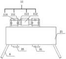
图1为本发明结构示意图。Figure 1 is a schematic structural diagram of the present invention.
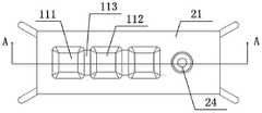
图2为本发明俯视结构示意图。FIG. 2 is a schematic top view of the structure of the present invention.
图3为A-A剖视示意图。FIG. 3 is a schematic cross-sectional view of A-A.
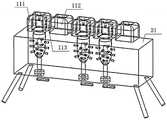
图4为本发明整体结构示意图。FIG. 4 is a schematic diagram of the overall structure of the present invention.
图5为本发明实施例2结构示意图。FIG. 5 is a schematic structural diagram of Embodiment 2 of the present invention.
图6为本发明实施例3结构示意图。FIG. 6 is a schematic structural diagram of Embodiment 3 of the present invention.
其中,固定桥-11,固位体-111,桥体-112,连接体-113,磁扣-114,基牙-12,牙冠-121,牙根-122,让位孔-1221,固定板-21,显压装置-22,压力传感器-221,灯珠-222,安装孔-23,通孔-24,固定盘-31,连接杆-32,万向节-33,滑杆-34,拨杆-35,PLC控制器-4,电源-5,支腿-6。Among them, fixed bridge-11, retainer-111, bridge-112, connector-113, magnetic buckle-114, abutment-12, crown-121, root-122, abdication hole-1221, fixing plate -21, pressure display device-22, pressure sensor-221, lamp bead-222, mounting hole-23, through hole-24, fixed plate-31, connecting rod-32, universal joint-33, sliding rod-34, Lever-35, PLC controller-4, power supply-5, outrigger-6.
具体实施方式Detailed ways
下面将结合本发明实施例中的附图,对本发明实施例中的技术方案进行清楚、完整地描述,显然,所描述的实施例仅仅是本发明一部分实施例,而不是全部的实施例。基于本发明中的实施例,本领域普通技术人员在没有做出创造性劳动前提下所获得的所有其他实施例,都属于本发明保护的范围。The technical solutions in the embodiments of the present invention will be clearly and completely described below with reference to the accompanying drawings in the embodiments of the present invention. Obviously, the described embodiments are only a part of the embodiments of the present invention, but not all of the embodiments. Based on the embodiments of the present invention, all other embodiments obtained by those of ordinary skill in the art without creative efforts shall fall within the protection scope of the present invention.
为使本发明的上述目的、特征和优点能够更加明显易懂,下面结合附图和具体实施方式对本发明作进一步详细的说明。In order to make the above objects, features and advantages of the present invention more clearly understood, the present invention will be described in further detail below with reference to the accompanying drawings and specific embodiments.
本发明提供一种基于压力传感器的模拟固定桥受力后运动方式的教具,包括义齿模型,底座,伸缩机构,PLC控制器4和电源5;义齿模型包括固定桥11和基牙12;PLC控制器4设置于底座一侧;The present invention provides a pressure sensor-based teaching aid for simulating the movement mode of a fixed bridge under force, including a denture model, a base, a telescopic mechanism, a
底座包括固定板21;固定板21顶面沿同一直线开设有若干固定槽;固定槽内侧壁固接有硅胶层;硅胶层与基牙12相适配;固定槽侧壁等间距开设有若干安装孔23;安装孔23内固定安装有显压装置22;显压装置22分别与电源5,PLC控制器4电性连接;显压装置22与基牙12相抵触;固定槽底部开设有通孔24;通孔24内滑动连接有伸缩机构;安装孔23和通孔24均贯穿硅胶层;固定桥11和底座为透明材质。The base includes a fixing
固定桥11包括固位体111,桥体112;任意相邻的两个固位体111或任意相邻的固位体111、桥体112之间固定连接有连接体113;固位体111底面开设有吸合槽;The fixed
基牙12包括牙冠121和牙根122;牙冠121和牙根122一体成型;牙冠121通过吸合槽与固位体111间隙配合;牙根122与硅胶层相适配;牙根122底部开设有让位孔1221;让位孔1221底部中心开设有滑孔;牙根122通过滑孔与伸缩机构滑动连接。The abutment 12 includes a
吸合槽内侧壁和牙冠121侧面对应位置均嵌设有若干磁扣114;固位体111通过若干磁扣114与牙冠121可拆卸连接。Several
伸缩机构包括滑杆34;滑杆34通过滑孔与牙根122滑动连接;滑杆34底面固接有万向节33的一端;万向节33的另一端固定连接有连接杆32的一端;连接杆32通过通孔24与底座滑动连接;连接杆32底端外侧开设有螺纹;连接杆32底端螺接有固定盘31;固定盘31顶面固定安装于底座底面;连接杆32底端贯穿固定盘31,并螺接有拨杆35的一端,连接杆32通过滑孔与牙根122滑动连接。The telescopic mechanism includes a sliding
相邻两固定槽之间的距离为桥体112宽度的整数倍。The distance between two adjacent fixing grooves is an integer multiple of the width of the
显压装置22包括压力传感器221和灯珠222;压力传感器221和灯珠222分别与PLC控制器4电性连接;压力传感器221与牙根122相抵触。The
底座底面四角部固接有四个支腿6。Four
让位孔1221深度为牙根122高度的0.33-0.4倍,让位孔1221直径大于滑孔直径。The depth of the
如图4,在本发明的实施例1中,固定桥11由两个固位体111,一个桥体112和两个连接体113组成(即双端固定桥),底座上开设有三个固定槽,其中相邻的两个固定槽之间间距分别为单颗牙齿的宽度和两颗牙齿宽度的间距;两基牙12之间间距为两颗牙齿的宽度;两基牙12与固定桥11可拆卸连接,模拟了缺失一个颗牙齿的口腔内,实施固定桥修复后的受力情况。As shown in FIG. 4 , in
如图5,在本发明的实施例2中,固定桥11由相邻的两个固位体111,一个桥体112和两个连接体113组成(即单端固定桥),底座上开设有三个固定槽,其中相邻的两个固定槽之间间距分别为单颗牙齿的宽度和两颗牙齿宽度的间距;两基牙12之间间距为单颗牙齿的宽度;两基牙12与固定桥11可拆卸连接,模拟了缺失一个颗牙齿且有两个相邻固位体111的口腔内,实施固定桥修复后的受力情况。As shown in FIG. 5, in Embodiment 2 of the present invention, the fixed
如图6,在本发明的实施例3中,固定桥11由三个固位体111,两个桥体112和四个连接体113组成(即复合固定桥),底座上开设有三个固定槽,其中相邻的两个固定槽之间间距分别为单颗牙齿的宽度和两颗牙齿宽度的间距;三个基牙12分别与固定槽相适配;三个基牙12与固定桥11可拆卸连接,模拟了相邻两颗牙齿两侧各缺失一个颗牙的口腔内,实施固定桥修复后的受力情况。As shown in FIG. 6 , in Embodiment 3 of the present invention, the fixed
在本发明的实施例4中,固位体111与基牙12可拆卸连接,固位体111内部嵌设的磁扣与基牙12的牙冠121外侧嵌设的磁扣相吸合,模拟了牙冠121和固位体111的粘结固定时的连接关系,牙冠121和固位体111施加外力破坏磁力后分开,模拟了固定桥11受外力后粘接破坏脱落的情况;旋转底座底部的拨杆35,实现了螺接在固定盘31上的连接杆32旋转上升,将万向节33底面与让位孔1221底面相平,滑杆34滑入滑孔内,给固定桥11施加各向外力,可以观察到牙根122挤压固定安装于安装孔23内的压力传感器221,压力传感器221给PLC控制器4相应的信号,PLC控制器4控制灯珠222发出亮光,即提示该处受到了压力的作用;继续旋转拨杆35,将连接杆32顶端与牙根122滑动连接后,实现了牙根122的固定,实现了牙周健康人群口腔情况的模拟展示。In
本发明公开了以下技术效果:The present invention discloses the following technical effects:
本发明能够将基牙的各向受力情况进行一个直观的展示,为教学提供了良好的指导;基牙在固定槽内具有一定的活动量,为显压装置的结果显示提供了一定的压力;并且基牙也可以固定于固定槽内,实现了模拟牙周健康及不健康人群固定桥修复受力后的运动情况。The invention can intuitively display the force of the abutment in all directions, and provides a good guide for teaching; the abutment has a certain amount of activity in the fixing groove, which provides a certain pressure for the result display of the pressure-sensitive device ; And the abutment can also be fixed in the fixed groove, which can simulate the movement of the periodontal healthy and unhealthy people after the fixed bridge is repaired.
固位体和牙冠通过磁扣相互吸合,模拟了牙冠和固位体的固定连接关系,牙冠和固位体施加外力破坏磁力后可分开,用于模拟固定桥粘接固定及受外力后粘接破坏脱落。The retainer and the dental crown are attracted to each other through the magnetic buckle, which simulates the fixed connection relationship between the dental crown and the retainer. After external force, the adhesive is damaged and falls off.
本发明整体结构简单,电路元件可拆卸更换,制造及维护成本不高,有利于大规模推广使用;仿真度高,真实模拟和呈现固定桥固位稳定原理学习中外力作用下固定桥各结构的运动趋势和变化。The overall structure of the invention is simple, the circuit components can be disassembled and replaced, the manufacturing and maintenance costs are not high, and it is conducive to large-scale popularization and use; Movement trends and changes.
本发明制作教具的比例可根据需要进行等比例扩大或缩小,以分别适应大、小教室课堂展示的需要。The proportion of the teaching aids made by the present invention can be expanded or reduced in equal proportions according to the needs, so as to respectively meet the needs of classroom display in large and small classrooms.
在本发明的描述中,需要理解的是,术语“纵向”、“横向”、“上”、“下”、“前”、“后”、“左”、“右”、“竖直”、“水平”、“顶”、“底”、“内”、“外”等指示的方位或位置关系为基于附图所示的方位或位置关系,仅是为了便于描述本发明,而不是指示或暗示所指的装置或元件必须具有特定的方位、以特定的方位构造和操作,因此不能理解为对本发明的限制。In the description of the present invention, it should be understood that the terms "portrait", "horizontal", "upper", "lower", "front", "rear", "left", "right", "vertical", The orientation or positional relationship indicated by "horizontal", "top", "bottom", "inner", "outer", etc. is based on the orientation or positional relationship shown in the drawings, and is only for the convenience of describing the present invention, rather than indicating or It is implied that the device or element referred to must have a particular orientation, be constructed and operate in a particular orientation, and therefore should not be construed as limiting the invention.
以上所述的实施例仅是对本发明的优选方式进行描述,并非对本发明的范围进行限定,在不脱离本发明设计精神的前提下,本领域普通技术人员对本发明的技术方案做出的各种变形和改进,均应落入本发明权利要求书确定的保护范围内。The above-mentioned embodiments are only to describe the preferred modes of the present invention, but not to limit the scope of the present invention. Without departing from the design spirit of the present invention, those of ordinary skill in the art can make various modifications to the technical solutions of the present invention. Variations and improvements should fall within the protection scope determined by the claims of the present invention.
Claims (6)
Priority Applications (1)
| Application Number | Priority Date | Filing Date | Title |
|---|---|---|---|
| CN202110249742.8ACN112785906B (en) | 2021-03-08 | 2021-03-08 | Teaching aid for simulating movement mode of stressed fixed bridge based on pressure sensor |
Applications Claiming Priority (1)
| Application Number | Priority Date | Filing Date | Title |
|---|---|---|---|
| CN202110249742.8ACN112785906B (en) | 2021-03-08 | 2021-03-08 | Teaching aid for simulating movement mode of stressed fixed bridge based on pressure sensor |
Publications (2)
| Publication Number | Publication Date |
|---|---|
| CN112785906A CN112785906A (en) | 2021-05-11 |
| CN112785906Btrue CN112785906B (en) | 2022-08-26 |
Family
ID=75762423
Family Applications (1)
| Application Number | Title | Priority Date | Filing Date |
|---|---|---|---|
| CN202110249742.8AActiveCN112785906B (en) | 2021-03-08 | 2021-03-08 | Teaching aid for simulating movement mode of stressed fixed bridge based on pressure sensor |
Country Status (1)
| Country | Link |
|---|---|
| CN (1) | CN112785906B (en) |
Family Cites Families (16)
| Publication number | Priority date | Publication date | Assignee | Title |
|---|---|---|---|---|
| GB2274062B (en)* | 1993-01-07 | 1996-11-13 | Leeds Precision Components Ltd | Tooth securement |
| JP2002282279A (en)* | 2001-01-22 | 2002-10-02 | Riichi Okasei | Artificial tooth |
| JP2002238924A (en)* | 2001-02-21 | 2002-08-27 | Kiichi Kitahara | Bridge |
| US20070106138A1 (en)* | 2005-05-26 | 2007-05-10 | Beiski Ben Z | Intraoral apparatus for non-invasive blood and saliva monitoring & sensing |
| US20090081618A1 (en)* | 2007-09-25 | 2009-03-26 | Lamar Frank R | System and method for immediate loading of fixed hybrid dental prostheses |
| CN102038555A (en)* | 2009-10-14 | 2011-05-04 | 乐园口腔株式会社 | Device for repairing teeth and accessories thereof |
| CN203183073U (en)* | 2013-03-21 | 2013-09-11 | 岳亚雄 | Novel adelomorphic fixed false tooth |
| BR112017013561A2 (en)* | 2015-01-13 | 2018-03-06 | Procter & Gamble | method and apparatus for assessing the effectiveness of dental sensitivity treatment with an oral care product |
| CN104966451B (en)* | 2015-07-08 | 2017-10-24 | 深圳职业技术学院 | A kind of complete denture setup trains demonstrating model |
| CN205041551U (en)* | 2015-08-28 | 2016-02-24 | 浙江工业大学 | Can simulate just abnormal power dynamic measurement device of three -dimensional that tooth removed |
| CN108066034B (en)* | 2016-11-10 | 2021-07-27 | 无锡时代天使医疗器械科技有限公司 | Tooth stress measuring device and method |
| CN206630710U (en)* | 2016-11-21 | 2017-11-14 | 东莞市爱嘉义齿有限公司 | A kind of Magnetic artificial tooth |
| CN206349062U (en)* | 2016-12-06 | 2017-07-21 | 皖南医学院 | Oral cavity exhibition religion model |
| CN111407451A (en)* | 2020-03-26 | 2020-07-14 | 宋业华 | Dental occlusion force measuring device and oral cavity wearing device |
| CN111728623A (en)* | 2020-06-28 | 2020-10-02 | 天津中科新显科技有限公司 | A kind of tooth bite force detection sensor, detection device and detection method |
| CN112294470A (en)* | 2020-11-21 | 2021-02-02 | 高峰医疗器械(无锡)有限公司 | A customized abutment crown card bridge |
- 2021
- 2021-03-08CNCN202110249742.8Apatent/CN112785906B/enactiveActive
Also Published As
| Publication number | Publication date |
|---|---|
| CN112785906A (en) | 2021-05-11 |
Similar Documents
| Publication | Publication Date | Title |
|---|---|---|
| Shillingburg et al. | Fundamentals of fixed prosthodontics | |
| CN206349062U (en) | Oral cavity exhibition religion model | |
| CN104966451B (en) | A kind of complete denture setup trains demonstrating model | |
| US3886661A (en) | Dental prosthetic device teaching aid | |
| CN101866570B (en) | Alveolar abscess cut model | |
| CN112785906B (en) | Teaching aid for simulating movement mode of stressed fixed bridge based on pressure sensor | |
| Dahab et al. | In vitro stress analysis study of different prosthetic options using single posterior implant for management of mandibular unilateral distal extension saddle | |
| CN206497665U (en) | A suture model of deep oral cavity tissue | |
| CN201402552Y (en) | Alveolar abscess incision model | |
| CN219497217U (en) | Periodontal probing training model | |
| Lynch et al. | The teaching of fixed partial dentures in undergraduate dental schools in Ireland and the United Kingdom | |
| CN203596135U (en) | Teaching-used maxillary oral cavity simulation model | |
| CN116343565A (en) | Periodontal probing training model | |
| US1512745A (en) | Demonstrator | |
| CN110310561B (en) | Periodontal probe depth training model | |
| CN1151480C (en) | High elastic dentognathic model | |
| CN103578338A (en) | Palate mouth cavity model simulation method and palate mouth cavity models for teaching | |
| CN211787811U (en) | Detachable dental teaching aid model convenient for wax tooth carving | |
| CN204904687U (en) | Tooth training demonstration model is arranged to complete mouthful artificial tooth | |
| Imbery et al. | Quality of impressions and work authorizations submitted by dental students supervised by prosthodontists and general dentists | |
| Rodrigues | Ceramic onlay: influence of the Deep Margin Elevation technique on stress distribution-a finite element Analysis | |
| CN211578214U (en) | Teaching model for peri-implantitis surgery of oral cavity | |
| CN209199445U (en) | A kind of mouth cavity display training pattern | |
| CN2410699Y (en) | High elastic occlusion model | |
| CN215298616U (en) | Pain simulation device for oral practice model |
Legal Events
| Date | Code | Title | Description |
|---|---|---|---|
| PB01 | Publication | ||
| PB01 | Publication | ||
| SE01 | Entry into force of request for substantive examination | ||
| SE01 | Entry into force of request for substantive examination | ||
| GR01 | Patent grant | ||
| GR01 | Patent grant |