CN112782485A - Method and system for measuring dielectric constant of mixed solid particulate matter and application - Google Patents
Method and system for measuring dielectric constant of mixed solid particulate matter and applicationDownload PDFInfo
- Publication number
- CN112782485A CN112782485ACN202110005016.1ACN202110005016ACN112782485ACN 112782485 ACN112782485 ACN 112782485ACN 202110005016 ACN202110005016 ACN 202110005016ACN 112782485 ACN112782485 ACN 112782485A
- Authority
- CN
- China
- Prior art keywords
- sample
- dielectric constant
- antenna
- solid particulate
- test
- Prior art date
- Legal status (The legal status is an assumption and is not a legal conclusion. Google has not performed a legal analysis and makes no representation as to the accuracy of the status listed.)
- Pending
Links
- 238000000034methodMethods0.000titleclaimsabstractdescription52
- 239000007787solidSubstances0.000titleclaimsabstractdescription47
- 239000013618particulate matterSubstances0.000titleclaimsabstractdescription41
- 238000012360testing methodMethods0.000claimsabstractdescription66
- 239000002184metalSubstances0.000claimsabstractdescription57
- 238000005259measurementMethods0.000claimsabstractdescription52
- 239000000463materialSubstances0.000claimsabstractdescription47
- 230000010287polarizationEffects0.000claimsabstractdescription42
- 239000010450olivineSubstances0.000claimsdescription19
- 229910052609olivineInorganic materials0.000claimsdescription19
- 229910000831SteelInorganic materials0.000claimsdescription16
- 239000010959steelSubstances0.000claimsdescription16
- 239000002245particleSubstances0.000claimsdescription10
- 238000010586diagramMethods0.000claimsdescription9
- 230000005540biological transmissionEffects0.000claimsdescription8
- 238000002474experimental methodMethods0.000claimsdescription8
- 238000000691measurement methodMethods0.000claimsdescription8
- 239000006260foamSubstances0.000claimsdescription7
- 239000003989dielectric materialSubstances0.000claimsdescription6
- 230000008569processEffects0.000claimsdescription6
- 230000009977dual effectEffects0.000claimsdescription4
- 230000008030eliminationEffects0.000claimsdescription4
- 238000003379elimination reactionMethods0.000claimsdescription4
- 239000002994raw materialSubstances0.000claimsdescription4
- 238000004590computer programMethods0.000claimsdescription3
- 230000006870functionEffects0.000claimsdescription3
- 238000012545processingMethods0.000claimsdescription3
- 230000003746surface roughnessEffects0.000claimsdescription3
- 230000008901benefitEffects0.000abstractdescription5
- 230000007547defectEffects0.000abstractdescription4
- 238000004519manufacturing processMethods0.000abstractdescription2
- 239000000523sampleSubstances0.000description92
- 238000013461designMethods0.000description5
- 239000000203mixtureSubstances0.000description5
- 230000008859changeEffects0.000description4
- 230000007423decreaseEffects0.000description4
- 230000008878couplingEffects0.000description3
- 230000001808coupling effectEffects0.000description3
- 238000010168coupling processMethods0.000description3
- 238000005859coupling reactionMethods0.000description3
- 239000000126substanceSubstances0.000description3
- 239000011358absorbing materialSubstances0.000description2
- 238000003491arrayMethods0.000description2
- 230000000694effectsEffects0.000description2
- 238000005516engineering processMethods0.000description2
- 238000004458analytical methodMethods0.000description1
- 230000002238attenuated effectEffects0.000description1
- 238000012937correctionMethods0.000description1
- 238000002592echocardiographyMethods0.000description1
- 230000007613environmental effectEffects0.000description1
- 229910052500inorganic mineralInorganic materials0.000description1
- 230000003993interactionEffects0.000description1
- 239000011344liquid materialSubstances0.000description1
- 239000011707mineralSubstances0.000description1
- 238000012986modificationMethods0.000description1
- 230000004048modificationEffects0.000description1
- 230000003287optical effectEffects0.000description1
- 230000035515penetrationEffects0.000description1
- 230000008092positive effectEffects0.000description1
- 230000005855radiationEffects0.000description1
- 239000004065semiconductorSubstances0.000description1
- 230000009897systematic effectEffects0.000description1
- XLYOFNOQVPJJNP-UHFFFAOYSA-NwaterSubstancesOXLYOFNOQVPJJNP-UHFFFAOYSA-N0.000description1
Images


Classifications
- G—PHYSICS
- G01—MEASURING; TESTING
- G01R—MEASURING ELECTRIC VARIABLES; MEASURING MAGNETIC VARIABLES
- G01R27/00—Arrangements for measuring resistance, reactance, impedance, or electric characteristics derived therefrom
- G01R27/02—Measuring real or complex resistance, reactance, impedance, or other two-pole characteristics derived therefrom, e.g. time constant
- G01R27/26—Measuring inductance or capacitance; Measuring quality factor, e.g. by using the resonance method; Measuring loss factor; Measuring dielectric constants ; Measuring impedance or related variables
- G01R27/2617—Measuring dielectric properties, e.g. constants
- G01R27/2635—Sample holders, electrodes or excitation arrangements, e.g. sensors or measuring cells
- G01R27/2658—Cavities, resonators, free space arrangements, reflexion or interference arrangements
- G01R27/2664—Transmission line, wave guide (closed or open-ended) or strip - or microstrip line arrangements
- G—PHYSICS
- G01—MEASURING; TESTING
- G01R—MEASURING ELECTRIC VARIABLES; MEASURING MAGNETIC VARIABLES
- G01R27/00—Arrangements for measuring resistance, reactance, impedance, or electric characteristics derived therefrom
- G01R27/02—Measuring real or complex resistance, reactance, impedance, or other two-pole characteristics derived therefrom, e.g. time constant
- G01R27/26—Measuring inductance or capacitance; Measuring quality factor, e.g. by using the resonance method; Measuring loss factor; Measuring dielectric constants ; Measuring impedance or related variables
- G01R27/2617—Measuring dielectric properties, e.g. constants
- G01R27/2635—Sample holders, electrodes or excitation arrangements, e.g. sensors or measuring cells
- G01R27/267—Coils or antennae arrangements, e.g. coils surrounding the sample or transmitter/receiver antennae
Landscapes
- Physics & Mathematics (AREA)
- General Physics & Mathematics (AREA)
- Measurement Of Resistance Or Impedance (AREA)
Abstract
Translated fromChinese
Description
Translated fromChinese技术领域technical field
本发明属于微波测量技术领域,尤其涉及一种混合固体颗粒物质介电常数测量方法、系统及应用。The invention belongs to the technical field of microwave measurement, and in particular relates to a method, system and application for measuring the dielectric constant of mixed solid particulate matter.
背景技术Background technique
目前:介电常数作为物质的特有属性,因其反映了电磁波与物质之间的相互作用,在电磁学领域中往往作为区分目标特性的重要参考依据。此外,各种散射反演模型大都是基于介电常数建立的,并以其作为输入参量,反演得出地物的包括厚度、含水量等重要特性。At present: Dielectric constant, as a unique property of matter, is often used as an important reference for distinguishing target properties in the field of electromagnetics because it reflects the interaction between electromagnetic waves and matter. In addition, most of the scattering inversion models are established based on the dielectric constant, which is used as an input parameter to invert to obtain important characteristics of ground objects, including thickness and water content.
目前介电常数主要通过两种方法获得。一是通过理论模型计算得到,利用物质的介电常数与温度、湿度、频率的经验关系,测得上述参数即可直接计算得到相应条件下的物质介电常数,但是大多数经验模型只适用于特定条件下,因而在实际使用中往往存在很大的局限性。二是通过实验测量得到,利用介电常数不同时,不同测试材料对电磁波的反射传输特性不同,测量出相应的参数,再由反演公式便能计算出物质的介电常数。At present, the dielectric constant is mainly obtained by two methods. One is calculated by theoretical model. Using the empirical relationship between the dielectric constant of the substance and temperature, humidity and frequency, the dielectric constant of the substance under the corresponding conditions can be directly calculated by measuring the above parameters. However, most empirical models are only applicable to Under certain conditions, there are often great limitations in practical use. The second is obtained through experimental measurement. When the dielectric constant is different, the reflection and transmission characteristics of different test materials to electromagnetic waves are different. The corresponding parameters are measured, and then the dielectric constant of the material can be calculated by the inversion formula.
实验测量方法主要包括谐振腔法、传输线法、网络参数法等,谐振腔法先将待测材料放入谐振腔中,观察记录样品放入前后的谐振腔谐振频率和品质因数Q值,从而可以计算出材料的复介电常数,但是由于该方法只能用于单频点,因此在频带方面有较大限制。同轴线探针法虽然能够实现频段扫频测量,但是其仅适用于内部均匀的液体物质,且其测量的介电常数只能代表样品小范围内的特性,并不能包括整体。传输线法通过将样品置于适当位置构成双端口网络,测量网络S参数得出其电磁参数,该方法对加工材料工艺精度有所要求,且对低损耗介质反应不灵敏。网络参数法是先测量出待测介质的网络传输参数,再经过一定的算法得到介质材料的介电参数。The experimental measurement methods mainly include resonant cavity method, transmission line method, network parameter method, etc. In the resonant cavity method, the material to be measured is first put into the resonant cavity, and the resonant frequency and quality factor Q value of the resonant cavity before and after the sample is observed and recorded, so that the The complex permittivity of the material is calculated, but since this method can only be used for a single frequency point, it has a large limitation in the frequency band. Although the coaxial probe method can realize the frequency sweep measurement, it is only suitable for the internal homogeneous liquid material, and the dielectric constant measured can only represent the characteristics of the sample in a small range, and cannot include the whole. The transmission line method forms a two-port network by placing the sample in an appropriate position, and measures the S-parameters of the network to obtain its electromagnetic parameters. The network parameter method is to measure the network transmission parameters of the medium to be measured first, and then obtain the dielectric parameters of the medium material through a certain algorithm.
通过上述分析,现有技术存在的问题及缺陷为:现有实验测量方法如谐振腔法只能用于单频点,在频带方面有较大限制,对低损耗介质反应不灵敏。值得注意的是,对介电参数进行测量难免会存在系统误差。传统测量方法由于两天线成镜像摆放且存在一定的入射角度,因此当电磁波到达待测样品表面时,并不能严格满足理想的平面波条件,且两天线之间存在一定耦合效应,在样品边缘处会产生边缘绕射和多次散射。Through the above analysis, the existing problems and defects of the existing technology are: the existing experimental measurement methods such as the resonant cavity method can only be used for a single frequency point, have a relatively large limitation in the frequency band, and are insensitive to low-loss media. It is worth noting that there will inevitably be systematic errors in the measurement of dielectric parameters. In the traditional measurement method, since the two antennas are placed in a mirror image and have a certain incident angle, when the electromagnetic wave reaches the surface of the sample to be measured, it cannot strictly meet the ideal plane wave conditions, and there is a certain coupling effect between the two antennas. Edge diffraction and multiple scattering occur.
解决以上问题及缺陷的难度为:为解决上述问题,主要有以下难点:减小系统误差,消除边缘绕射以及天线耦合的影响。The difficulty of solving the above problems and defects is: In order to solve the above problems, there are mainly the following difficulties: reducing the system error, eliminating the influence of edge diffraction and antenna coupling.
解决以上问题及缺陷的意义为:使测试系统满足平面波条件,消除边缘绕射以及天线旁瓣耦合,可有效减小系统误差,提高测量精度使反演更准确。The significance of solving the above problems and defects is to make the test system meet the plane wave condition, eliminate edge diffraction and antenna sidelobe coupling, which can effectively reduce the system error, improve the measurement accuracy and make the inversion more accurate.
发明内容SUMMARY OF THE INVENTION
针对现有技术存在的问题,本发明提供了一种混合固体颗粒物质介电常数测量方法、系统及应用。In view of the problems existing in the prior art, the present invention provides a method, system and application for measuring the dielectric constant of mixed solid particulate matter.
本发明是这样实现的,一种混合固体颗粒物质介电常数测量方法,所述混合固体颗粒物质介电常数测量方法包括:The present invention is realized in this way, a method for measuring the dielectric constant of mixed solid particulate matter, the method for measuring the dielectric constant of mixed solid particulate matter includes:
对试验平台进行设计与搭建满足平面波条件;使得天线到样品距离大于远场距离,并设置较小入射角度,使得当电磁波到达待测样品表面时,能严格满足理想的平面波条件,同时消除天线之间的耦合效应。The test platform is designed and built to meet the plane wave conditions; the distance from the antenna to the sample is greater than the far-field distance, and a small incident angle is set, so that when the electromagnetic wave reaches the surface of the sample to be tested, it can strictly meet the ideal plane wave conditions, and eliminate the antenna's interference. coupling effect between.
待测固体颗粒物质进行混合使其满足样品表面无限大、样品表面无限厚以及样品表面光滑条件;混合颗粒物质样品的制作最终影响到反演算法的正确性,增大面积,能够有效消除边缘绕射。The solid particulate matter to be tested is mixed so that the sample surface is infinite, the sample surface is infinitely thick, and the sample surface is smooth. shoot.
对测试场使用金属板双极化定标消除不同极化相位中心误差;用已知反射系数的金属板定标数据作为系统的修正量。Use metal plate dual-polarization calibration on the test field to eliminate the center errors of different polarization phases; use the metal plate calibration data with known reflection coefficients as the correction of the system.
对准备的材料进行垂直极化波和水平极化波下网络参数测量;反演方法基于菲涅尔公式得出介质复介电常数,由水平极化下和垂直极化下的散射参数得出菲涅尔反射系数之比。The network parameters are measured under the vertically polarized wave and the horizontally polarized wave on the prepared material; the inversion method is based on the Fresnel formula to obtain the complex permittivity of the medium, which is obtained from the scattering parameters under the horizontal polarization and the vertical polarization Ratio of Fresnel reflection coefficients.
对得到的测量数据进行反演最终得出介质的复介电常数。The complex permittivity of the medium is finally obtained by inversion of the obtained measurement data.
进一步,所述混合固体颗粒物质介电常数测量方法搭建试验场地,将发射天线和接收天线分别与矢量网络分析仪的两个端口相连,测量介质材料的散射参数的振幅和相位再反演得出其复介电常数;测试场地布置和待测材料需要满足四个测量条件:平面波条件、样品表面无限大、样品表面无限厚和样品表面光滑;Further, the method for measuring the dielectric constant of the mixed solid particulate matter builds a test site, connects the transmitting antenna and the receiving antenna to the two ports of the vector network analyzer respectively, and measures the amplitude and phase of the scattering parameters of the dielectric material and then inverts the result. Its complex permittivity; the layout of the test site and the material to be tested need to meet four measurement conditions: plane wave condition, infinite sample surface, infinite sample surface thickness and smooth sample surface;
满足平面波条件:菲涅尔反射定律要求入射到介质表面的电磁波为平面波或近似平面波,根据天线的远近场判别公式,当待测材料处于天线发射场的远场区域时,照射到材料表面的电磁波便可以视为平面波,天线与目标的距离L、天线最大口径D以及电磁波波长λ有如下判别式:Satisfy the plane wave condition: Fresnel's law of reflection requires that the electromagnetic wave incident on the surface of the medium is a plane wave or an approximate plane wave. According to the antenna's near-field discrimination formula, when the material to be tested is in the far-field area of the antenna's emission field, the electromagnetic wave irradiated on the surface of the material It can be regarded as a plane wave. The distance L between the antenna and the target, the maximum diameter D of the antenna, and the wavelength λ of the electromagnetic wave have the following discriminants:


对于喇叭天线,天线最大口径D即为其长轴大小;根据天线参数,得出其不同频率下的平面波条件,根据工作频率范围两者距离只要大于22GHz时的1.617m;For the horn antenna, the maximum diameter D of the antenna is the size of its long axis; according to the antenna parameters, the plane wave conditions at different frequencies are obtained, and the distance between the two is only greater than 1.617m at 22GHz according to the operating frequency range;
实验室布置应该如下:在测试区域底部放置吸波泡沫板,泡沫板上放置测试样品,两个天线支架置于待测样品的两侧,收发天线分别安装在可调节高度和入射角度的两个天线支架上,通过调节天线支架的高度和角度,使得两个天线关于待测样品成镜像,且满足入射角等于反射角,再将收发天线分别与矢量网络分析仪的两个端口相连。The laboratory layout should be as follows: a wave-absorbing foam board is placed at the bottom of the test area, the test sample is placed on the foam board, two antenna brackets are placed on both sides of the sample to be tested, and the transceiver antennas are installed on two adjustable height and incident angle. On the antenna bracket, adjust the height and angle of the antenna bracket so that the two antennas are mirror images of the sample to be tested, and the incident angle is equal to the reflection angle, and then the transceiver antennas are respectively connected to the two ports of the vector network analyzer.
进一步,准备待测材料:选择金属钢珠和橄榄石颗粒作为原材料并按照体积比1:3和1:4混合;Further, prepare the material to be tested: select metal steel balls and olivine particles as raw materials and mix them according to the volume ratio of 1:3 and 1:4;
(1)样品表面无限大:样品表面的大小可根据Kirchhoff积分公式确定,它是天线到待测样品的距离、喇叭天线增益、方向图以及入射角的函数,并反映了局部菲涅尔反射系数,当Fresnel带个数N>10时,认为样品面积是无限大的,根据菲涅尔周线的长轴a和短轴b:(1) The sample surface is infinite: the size of the sample surface can be determined according to the Kirchhoff integral formula, which is a function of the distance from the antenna to the sample to be measured, the gain of the horn antenna, the pattern and the incident angle, and reflects the local Fresnel reflection coefficient , when the number of Fresnel bands N>10, the sample area is considered to be infinite. According to the long axis a and short axis b of the Fresnel contour:

其中,
(2)样品表面无限厚:衰减系数Γ和介电常数如下:(2) The sample surface is infinitely thick: the attenuation coefficient Γ and the dielectric constant are as follows:

当电磁波以θ为入射角入射到介质表面时,介质厚度最小满足:When the electromagnetic wave is incident on the surface of the medium with θ as the incident angle, the minimum thickness of the medium satisfies:

因用10+0.1j代表橄榄石介电常数,80+20j代表金属介电常数,分别代入上式预估;Since 10+0.1j is used to represent the dielectric constant of olivine, and 80+20j is used to represent the dielectric constant of metal, they are respectively substituted into the above formula to estimate;
(3)样品表面光滑:根据实验可知,样品表面只要满足基尔霍夫模型KAM和小扰动模型SPM运用菲涅尔定律进行反演:(3) The surface of the sample is smooth: According to the experiment, as long as the surface of the sample satisfies the Kirchhoff model KAM and the small disturbance model SPM, the Fresnel law is used for inversion:

其中,k=2π/λ是波数,s是表面均方根高度,l是表面相关长度。where k=2π/λ is the wave number, s is the surface rms height, and l is the surface correlation length.
进一步,金属板双极化定标:首先在测试区域放置与测试样品大小相同且反射系数为已知RcV=-RcH=1的金属板,通过转动喇叭天线方向来调整不同极化方式,具体有收发天线都为水平极化和垂直极化,分别测量其散射参数

进一步,开展待测材料测量:完成金属板定标后,不移动天线,不改变传输路径,保持测试现场状态与定标时候一致,将准备好的待测材料放置于测试区域,同样通过转动喇叭天线方向来调整不同极化方式,具体有收发天线都为水平极化和垂直极化,分别测量其散射参数S21V和S21H。Further, carry out the measurement of the material to be tested: after completing the calibration of the metal plate, do not move the antenna, do not change the transmission path, keep the test site state consistent with the calibration time, place the prepared material to be tested in the test area, and also rotate the horn. Different polarization modes are adjusted according to the direction of the antenna. Specifically, the transmitting and receiving antennas are both horizontally polarized and vertically polarized, and their scattering parameters S21V and S21H are measured respectively.
进一步,对测量数据进行反演计算得出复介电常数:根据菲涅尔反射定律,介质的反射系数与介电常数有如下的关系,根据反射系数来反演得出其介电常数:Further, the complex permittivity is obtained by inverting the measured data: according to the Fresnel reflection law, the reflection coefficient of the medium has the following relationship with the permittivity, and the permittivity is obtained by inversion according to the reflection coefficient:


其中,εr=ε′r-jε″r为介质复介电常数,由上式可知其只与反射系数RH、RV入射角θ有关,由矢量网络分析仪获得的是网络参数S21的相位信息和幅度信息,幅值反映网络增益的大小,相位反映电磁波通过整个系统后的延迟;通常有如下关系式:Among them, εr =ε′r-jε ″r is the complex permittivity of the medium, it can be seen from the above formula that it is only related to the reflection coefficientsRH and RV incident angle θ, and the network parameter S21 obtained by the vector network analyzer The phase information and amplitude information of , the amplitude reflects the size of the network gain, and the phase reflects the delay after the electromagnetic wave passes through the entire system; usually there is the following relationship:

A为整个测试系统的比例系数,比例系数与样品表面粗糙度、电磁波传播路径长度以及测试仪器内部参数有关,所以在同一个测试系统中A是不变的。通过测量出的S21H和S21V得到RH和RV。A is the proportional coefficient of the entire test system, which is related to the surface roughness of the sample, the length of the electromagnetic wave propagation path, and the internal parameters of the test instrument, so A is constant in the same test system. RH and RV are obtained from the measured S21H and S21V .
进一步包括:Further includes:
(1)处理上面获得的金属板定标数据,利用已知的金属板反射系数关系RcV=-RcH=1,并且引入相位中心偏移误差δ,则金属板定标中获得的垂直极化波与水平极化波散射参数之比为:(1) Process the metal plate calibration data obtained above, use the known metal plate reflection coefficient relationship RcV =-RcH =1, and introduce the phase center offset error δ, then the obtained metal plate calibration The ratio of the vertically polarized wave to the horizontally polarized wave scattering parameters is:

(2)因为测量过程中保持了测试系统状态始终不变,即比例系数A不变,对样品数据做相同处理,则样品测量中获得的垂直极化波与水平极化波散射参数之比为:(2) Since the state of the test system is kept unchanged during the measurement process, that is, the proportional coefficient A remains unchanged, and the same processing is performed on the sample data, the ratio of the scattering parameters of the vertically polarized wave and the horizontally polarized wave obtained in the sample measurement is: :


解出介电常数反演公式:Solve the dielectric constant inversion formula:

其中,
本发明的另一目的在于提供一种计算机设备,所述计算机设备包括存储器和处理器,所述存储器存储有计算机程序,所述计算机程序被所述处理器执行时,使得所述处理器执行如下步骤:Another object of the present invention is to provide a computer device, the computer device includes a memory and a processor, the memory stores a computer program, and when the computer program is executed by the processor, the processor executes the following step:
对试验平台进行设计与搭建满足平面波条件;Design and build the test platform to meet the plane wave conditions;
待测固体颗粒物质进行混合使其满足样品表面无限大、样品表面无限厚以及样品表面光滑条件;The solid particulate matter to be tested is mixed to meet the conditions of infinite sample surface, infinite sample surface thickness and smooth sample surface;
对测试场使用金属板双极化定标消除不同极化相位中心误差;Use metal plate dual-polarization calibration on the test field to eliminate phase center errors of different polarizations;
对准备的材料进行垂直极化波和水平极化波下网络参数测量;Measure the network parameters under the vertically polarized wave and the horizontally polarized wave on the prepared materials;
对得到的测量数据进行反演最终得出介质的复介电常数。The complex permittivity of the medium is finally obtained by inversion of the obtained measurement data.
本发明的另一目的在于提供一种实施所述混合固体颗粒物质介电常数测量方法的混合固体颗粒物质介电常数测量系统,所述混合固体颗粒物质介电常数测量系统包括:Another object of the present invention is to provide a mixed solid particulate matter dielectric constant measurement system for implementing the mixed solid particulate matter dielectric constant measurement method, the mixed solid particulate matter dielectric constant measurement system comprising:
平台搭建模块,用于对试验平台进行设计与搭建使其满足平面波条件;The platform building module is used to design and build the test platform to meet the plane wave conditions;
样品混合模块,用于将待测固体颗粒物质进行混合使其满足样品表面无限大、样品表面无限厚以及样品表面光滑条件;The sample mixing module is used to mix the solid particulate matter to be tested to meet the conditions of infinite sample surface, infinite sample surface thickness and smooth sample surface;
误差消除模块,用于对测试场使用金属板双极化定标消除不同极化相位中心误差;The error elimination module is used to eliminate the phase center errors of different polarizations by using the metal plate dual-polarization calibration for the test field;
参数测量模块,用于对准备的材料进行垂直极化波和水平极化波下网络参数测量;The parameter measurement module is used to measure the network parameters of the prepared materials under the vertically polarized wave and the horizontally polarized wave;
复介电常数模块,用于对得到的测量数据进行反演最终得出介质的复介电常数。The complex permittivity module is used to invert the obtained measurement data and finally obtain the complex permittivity of the medium.
本发明的另一目的在于提供一种微波测量终端,所述微波测量终端用于实现所述的混合固体颗粒物质介电常数测量方法。Another object of the present invention is to provide a microwave measurement terminal, which is used for implementing the method for measuring the dielectric constant of mixed solid particulate matter.
结合上述的所有技术方案,本发明所具备的优点及积极效果为:本发明是针对混合固体颗粒物质基于网络参数的介电常数测量方法,它不要求与样品接触,因而不会破坏待测物原始状态,且可以根据需要选择地点放置,具有较高的自由度,且克服了谐振腔法只能单点测量的缺点,实现了大范围多频段扫描。Combined with all the above technical solutions, the advantages and positive effects of the present invention are as follows: the present invention is a method for measuring the dielectric constant of mixed solid particulate matter based on network parameters, it does not require contact with the sample, so it will not damage the object to be tested It is in the original state, and can be placed in a location according to needs, with a high degree of freedom, and overcomes the shortcomings of the resonant cavity method that can only be measured at a single point, and realizes a wide range of multi-band scanning.
附图说明Description of drawings
为了更清楚地说明本申请实施例的技术方案,下面将对本申请实施例中所需要使用的附图做简单的介绍,显而易见地,下面所描述的附图仅仅是本申请的一些实施例,对于本领域普通技术人员来讲,在不付出创造性劳动的前提下还可以根据这些附图获得其他的附图。In order to explain the technical solutions of the embodiments of the present application more clearly, the following will briefly introduce the drawings that need to be used in the embodiments of the present application. Obviously, the drawings described below are only some embodiments of the present application. For those of ordinary skill in the art, other drawings can also be obtained from these drawings without creative effort.
图1是本发明实施例提供的混合固体颗粒物质介电常数测量方法流程图。FIG. 1 is a flowchart of a method for measuring the dielectric constant of mixed solid particulate matter provided by an embodiment of the present invention.
图2是本发明实施例提供的混合固体颗粒物质介电常数测量系统的结构示意图;2 is a schematic structural diagram of a system for measuring the dielectric constant of mixed solid particulate matter provided by an embodiment of the present invention;
图2中:1、平台搭建模块;2、样品混合模块;3、误差消除模块;4、参数测量模块;5、复介电常数模块。In Figure 2: 1. Platform building module; 2. Sample mixing module; 3. Error elimination module; 4. Parameter measurement module; 5. Complex permittivity module.
图3是本发明实施例提供的混合固体颗粒物质介电常数测量方法的实现流程图。FIG. 3 is a flow chart of the implementation of the method for measuring the dielectric constant of mixed solid particulate matter provided by an embodiment of the present invention.
图4是本发明实施例提供的室内介电常数矢量测试平台示意图。FIG. 4 is a schematic diagram of an indoor dielectric constant vector test platform provided by an embodiment of the present invention.
图5是本发明实施例提供的喇叭天线不同频率下对应的平面波条件示意图。FIG. 5 is a schematic diagram of plane wave conditions corresponding to different frequencies of the horn antenna provided by the embodiment of the present invention.
图6是本发明实施例提供的室内暗室测量系统现场布置图。FIG. 6 is a site layout diagram of an indoor darkroom measurement system provided by an embodiment of the present invention.
图7是本发明实施例提供的金属钢珠与橄榄石颗粒混合样品。FIG. 7 is a mixed sample of metal steel balls and olivine particles provided in an embodiment of the present invention.
图7中:(a)为金属钢珠与橄榄石颗粒体积比例为1:3混合样品;(b)为金属钢珠与橄榄石颗粒体积比例为1:4混合样品。In Fig. 7: (a) is a mixed sample of metal steel balls and olivine particles in a volume ratio of 1:3; (b) is a mixed sample of metal steel balls and olivine particles in a volume ratio of 1:4.
图8是本发明实施例提供的喇叭天线不同频率下对应的样品无限大条件示意图。FIG. 8 is a schematic diagram showing the infinite size of the sample corresponding to different frequencies of the horn antenna provided by the embodiment of the present invention.
图9是本发明实施例提供的喇叭天线不同频率下对应的样品无限厚条件示意图。FIG. 9 is a schematic diagram of the infinite thickness condition of the corresponding sample under different frequencies of the horn antenna provided by the embodiment of the present invention.
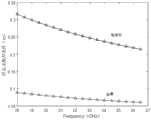
图10是本发明实施例提供的橄榄石颗粒和金属钢珠不同比例混合介电常数反演结果示意图。FIG. 10 is a schematic diagram of an inversion result of the dielectric constant of the mixture of olivine particles and metal steel balls in different proportions according to an embodiment of the present invention.
图10中:(a)为样品介电常数实部反演结果;(b)为样品介电常数虚部反演结果。In Figure 10: (a) is the inversion result of the real part of the sample dielectric constant; (b) is the inversion result of the imaginary part of the sample dielectric constant.
具体实施方式Detailed ways
为了使本发明的目的、技术方案及优点更加清楚明白,以下结合实施例,对本发明进行进一步详细说明。应当理解,此处所描述的具体实施例仅仅用以解释本发明,并不用于限定本发明。In order to make the objectives, technical solutions and advantages of the present invention clearer, the present invention will be further described in detail below with reference to the embodiments. It should be understood that the specific embodiments described herein are only used to explain the present invention, but not to limit the present invention.
针对现有技术存在的问题,本发明提供了一种混合固体颗粒物质介电常数测量方法、系统及应用,下面结合附图对本发明作详细的描述。In view of the problems existing in the prior art, the present invention provides a method, system and application for measuring the dielectric constant of mixed solid particulate matter. The present invention is described in detail below with reference to the accompanying drawings.
如图1所示,本发明提供的混合固体颗粒物质介电常数测量方法包括以下步骤:As shown in Figure 1, the method for measuring the dielectric constant of mixed solid particulate matter provided by the present invention comprises the following steps:
S101:对试验平台进行设计与搭建使其满足平面波条件;S101: Design and build the test platform to meet the plane wave conditions;
S102:待测固体颗粒物质进行混合使其满足样品表面无限大、样品表面无限厚以及样品表面光滑条件;S102: The solid particulate matter to be tested is mixed so that the sample surface is infinite, the sample surface is infinitely thick, and the sample surface is smooth;
S103:对测试场使用金属板双极化定标消除不同极化相位中心误差;S103: Use metal plate dual-polarization calibration on the test field to eliminate phase center errors of different polarizations;
S104:对准备的材料进行垂直极化波和水平极化波下网络参数测量;S104: Measure the network parameters under the vertically polarized wave and the horizontally polarized wave on the prepared material;
S105:对得到的测量数据进行反演最终得出介质的复介电常数。S105: Invert the obtained measurement data to finally obtain the complex permittivity of the medium.
本发明提供的混合固体颗粒物质介电常数测量方法业内的普通技术人员还可以采用其他的步骤实施,图1的本发明提供的混合固体颗粒物质介电常数测量方法仅仅是一个具体实施例而已。Those skilled in the art of the method for measuring the dielectric constant of mixed solid particulate matter provided by the present invention can also implement other steps. The method for measuring the dielectric constant of mixed solid particulate matter provided by the present invention in FIG. 1 is only a specific example.
如图2所示,本发明提供的混合固体颗粒物质介电常数测量系统包括:As shown in Figure 2, the system for measuring the dielectric constant of mixed solid particulate matter provided by the present invention includes:
平台搭建模块1,用于对试验平台进行设计与搭建使其满足平面波条件;
样品混合模块2,用于将待测固体颗粒物质进行混合使其满足样品表面无限大、样品表面无限厚以及样品表面光滑条件;The
误差消除模块3,用于对测试场使用金属板双极化定标消除不同极化相位中心误差;
参数测量模块4,用于对准备的材料进行垂直极化波和水平极化波下网络参数测量;The
复介电常数模块5,用于对得到的测量数据进行反演最终得出介质的复介电常数。The
下面结合附图对本发明的技术方案作进一步的描述。The technical solutions of the present invention will be further described below with reference to the accompanying drawings.
本发明以解决混合固体颗粒物质介电常数测量问题;克服了谐振腔法和波导法对样品材料加工工艺和单频点的限制,克服了同轴线探针法只能测量介质材料局部区域的缺点,拥有多频段覆盖且不会破坏材料原始状态的优势。传统测量方法难以避免的是无法严格满足平面波条件,从而反演精度不高,这是因为入射角过大导致的,同时还引起了收发天线之间的耦合增强。因此改进了测量方式,如图3所示,具体步骤:对试验平台进行设计与搭建使其满足平面波条件;对待测固体颗粒物质进行混合使其满足样品表面无限大、样品表面无限厚以及样品表面光滑条件;对测试场使用金属板双极化定标消除不同极化相位中心误差;对准备的材料进行垂直极化波和水平极化波下网络参数测量;对得到的测量数据进行反演最终得出复介电常数。The invention solves the problem of measuring the dielectric constant of mixed solid particles; overcomes the limitation of the resonant cavity method and the waveguide method on the processing technology and single frequency point of the sample material, and overcomes the problem that the coaxial probe method can only measure the local area of the dielectric material. The disadvantage is that it has the advantage of multi-band coverage without destroying the original state of the material. It is unavoidable that the traditional measurement method cannot strictly meet the plane wave conditions, so the inversion accuracy is not high, which is caused by the excessively large incident angle, and also causes the coupling enhancement between the transmitting and receiving antennas. Therefore, the measurement method is improved, as shown in Figure 3. The specific steps are: design and build the test platform to meet the plane wave conditions; mix the solid particulate matter to be measured so that the sample surface is infinite, the sample surface is infinitely thick and the sample surface is infinite. Smooth conditions; use metal plate dual-polarization calibration on the test field to eliminate the center errors of different polarization phases; measure the network parameters of the prepared materials under vertically polarized waves and horizontally polarized waves; invert the obtained measurement data and finally Get the complex permittivity.
如图3所示,本发明提供的混合固体颗粒物质介电常数测量方法具体包括以下步骤:As shown in Figure 3, the method for measuring the dielectric constant of mixed solid particulate matter provided by the present invention specifically includes the following steps:
(1)搭建试验场地,图4所示为室内测试平台布置。自由空间法反演物质介电常数是建立在菲涅尔反射定律基础上的,基本原理是将发射天线和接收天线分别与矢量网络分析仪的两个端口相连,测量介质材料的散射参数的振幅和相位再反演得出其复介电常数。基于上述原理,测试场地布置和待测材料需要满足四个测量条件:平面波条件、样品表面无限大、样品表面无限厚和样品表面光滑。(1) Build the test site, and Figure 4 shows the layout of the indoor test platform. The inversion of the dielectric constant of the material by the free space method is based on the Fresnel reflection law. and phase inversion to obtain its complex permittivity. Based on the above principles, the layout of the test site and the material to be tested need to meet four measurement conditions: plane wave condition, infinite sample surface, infinite sample surface thickness and smooth sample surface.
为了使本发明实验场布置更加清晰明白,特提供部分实验仪器清单及场地参数,需要说明的是,设置矢网扫频范围时选择20GHz~22GHz即为工作频率,且所有仪器选择及其摆放设置仅供参考。In order to make the layout of the experimental field of the present invention clearer, a list of some experimental instruments and field parameters are provided. It should be noted that when setting the sweep frequency range of the vector grid, selecting 20GHz to 22GHz is the working frequency, and all instruments are selected and placed. Settings are for reference only.
表1部分仪器及场地参数Table 1 Parts of instruments and site parameters
(1.1)首先需满足平面波条件:菲涅尔反射定律要求入射到介质表面的电磁波为平面波或近似平面波,根据天线的远近场判别公式,当待测材料处于天线发射场的远场区域时,照射到材料表面的电磁波便可以视为平面波。因此天线与目标的距离L、天线最大口径D以及电磁波波长λ有如下判别式:(1.1) The plane wave condition must be satisfied first: Fresnel's law of reflection requires that the electromagnetic wave incident on the surface of the medium is a plane wave or an approximate plane wave. According to the antenna's near-field discrimination formula, when the material to be tested is in the far-field area of the antenna's emission field, the radiation Electromagnetic waves that reach the surface of a material can be considered plane waves. Therefore, the distance L between the antenna and the target, the maximum diameter D of the antenna and the wavelength λ of the electromagnetic wave have the following discriminants:


对于喇叭天线,天线最大口径D即为其长轴大小。根据上述天线参数,得出其不同频率下的平面波条件,如图5所示,天线与目标的距离L随着频率而增大,根据工作频率范围两者距离只要大于22GHz时的1.617m即可。现场喇叭天线高度h=163.5cm、入射角θ=35°满足平面波条件。For a horn antenna, the maximum diameter D of the antenna is the size of its long axis. According to the above antenna parameters, the plane wave conditions at different frequencies are obtained. As shown in Figure 5, the distance L between the antenna and the target increases with the frequency. According to the operating frequency range, the distance between the two is only greater than 1.617m at 22GHz. . The height h=163.5cm and the incident angle θ=35° of the field horn antenna satisfy the plane wave conditions.
(1.2)为了消除上述天线耦合效应,转动天线以小角度θ=35°入射以提高测量精度,该实验宜安排在低噪声环境中进行,图6为本实例提供的实验室布置现场图,具体实验室布置应该如下:在测试区域底部放置吸波泡沫板,泡沫板上放置测试样品,以防止电磁波透过测试材料后,接触地面产生反射回波,在测试样品四周布置吸波材料以尽量减小环境干扰,即除了介质表面反射的回波之外其他能量都被吸收,两个天线支架置于待测样品的两侧,收发天线分别安装在可调节高度和入射角度的两个天线支架上,通过调节天线支架的高度和角度,使得两个天线关于待测样品成镜像,且满足入射角等于反射角,再将收发天线分别依次连接功率放大器、矢量网络分析仪的两个端口。(1.2) In order to eliminate the above-mentioned antenna coupling effect, rotate the antenna at a small angle of θ=35° to improve the measurement accuracy. The experiment should be carried out in a low-noise environment. Figure 6 provides a site map of the laboratory layout for this example. The laboratory layout should be as follows: place a wave-absorbing foam board at the bottom of the test area, and place the test sample on the foam board to prevent the electromagnetic wave from passing through the test material and contact the ground to generate reflected echoes, and arrange the wave-absorbing material around the test sample to minimize the Small environmental interference, that is, all other energy except the echo reflected on the surface of the medium is absorbed. Two antenna brackets are placed on both sides of the sample to be tested, and the transceiver antennas are installed on two antenna brackets with adjustable height and incident angle. , by adjusting the height and angle of the antenna support, so that the two antennas are mirror images about the sample to be tested, and the incident angle is equal to the reflection angle, and then the transceiver antenna is connected to the two ports of the power amplifier and the vector network analyzer in turn.
(2)准备待测材料:由现有条件,选择金属钢珠和橄榄石颗粒作为原材料并按照体积比1:3和1:4混合,如图7为本实例提供的样品图,分别为金属钢珠与橄榄石体积比1:3和1:4。根据上面所述,介质材料的选取与规格参数还需满足几个测试条件,即样品表面无限大、样品表面无限厚以及样品表面光滑。(2) Prepare the material to be tested: According to the existing conditions, select metal steel balls and olivine particles as raw materials and mix them according to the volume ratio of 1:3 and 1:4, as shown in Figure 7 for the sample diagram provided for this example, which are metal steel balls respectively. With olivine volume ratio 1:3 and 1:4. According to the above, the selection and specification parameters of the dielectric material also need to meet several test conditions, that is, the sample surface is infinite, the sample surface is infinitely thick, and the sample surface is smooth.
(2.1)样品表面无限大:样品表面的大小可根据Kirchhoff积分公式来确定,它是天线到待测样品的距离、喇叭天线增益、方向图以及入射角的函数,并反映了局部菲涅尔反射系数。一般认为,当Fresnel带个数N>10时,便可以认为样品面积是无限大的。因此根据菲涅尔周线的长轴a和短轴b:(2.1) The sample surface is infinite: the size of the sample surface can be determined according to the Kirchhoff integral formula, which is a function of the distance from the antenna to the sample to be measured, the gain of the horn antenna, the pattern and the incident angle, and reflects the local Fresnel reflection coefficient. It is generally believed that when the number of Fresnel bands N>10, the sample area can be considered to be infinite. So according to the major axis a and the minor axis b of the Fresnel contour:

其中,
(2.2)样品表面无限厚:对于电磁波来说,当其在介质中传输衰减完全且走过的路程刚好为一个来回时,便可以认为这个介质是无限厚的,在实际使用中当信号衰减大于40dB时介质就满足了无限厚条件,衰减系数Γ和介电常数如下:(2.2) The surface of the sample is infinitely thick: For electromagnetic waves, when the transmission attenuation in the medium is completely attenuated and the distance traveled is exactly one round trip, the medium can be considered to be infinitely thick. In actual use, when the signal attenuation is greater than At 40dB, the medium satisfies the condition of infinite thickness, and the attenuation coefficient Γ and the dielectric constant are as follows:

不同的待测介质,Av的值便会不同,一般测量固体的介电常数时有Av=1,而穿透深度表示为电磁波幅度值衰减到只有其在表层处的1/e时所穿过介质的厚度,所以当电磁波以θ为入射角入射到介质表面时,介质厚度最小满足以下便可认为无限厚:Different medium to be measured, the value ofAv will be different. Generally, when measuring the dielectric constant of solid, there isAv = 1, and the penetration depth is expressed as the attenuation of the electromagnetic wave amplitude value to only 1/e at the surface. Through the thickness of the medium, when the electromagnetic wave is incident on the surface of the medium with θ as the incident angle, the minimum thickness of the medium can be considered as infinitely thick:

因为选取的材料为金属钢珠和橄榄石颗粒,参考相关资料,用10+0.1j代表橄榄石介电常数,80+20j代表金属介电常数,分别代入上式预估。如图9所示,金属的厚度条件明显小于橄榄石且都随着频率减小,因此厚度只需大于20GHz时的0.2848m即可。Because the selected materials are metal steel balls and olivine particles, refer to relevant information, use 10+0.1j to represent the dielectric constant of olivine, and 80+20j to represent the dielectric constant of metal, which are respectively substituted into the above formula to estimate. As shown in Figure 9, the thickness of the metal is obviously smaller than that of olivine and decreases with frequency, so the thickness only needs to be greater than 0.2848m at 20GHz.
(2.3)样品表面光滑:根据实验可知,样品表面只要满足基尔霍夫模型(KAM)和小扰动模型(SPM)就可运用菲涅尔定律进行反演:(2.3) The surface of the sample is smooth: According to the experiments, as long as the surface of the sample satisfies the Kirchhoff model (KAM) and the small perturbation model (SPM), the Fresnel law can be used for inversion:

其中,k=2π/λ是波数,s是表面均方根高度,l是表面相关长度。where k=2π/λ is the wave number, s is the surface rms height, and l is the surface correlation length.
(3)金属板双极化定标:由于在两种极化下喇叭天线的相位中心可能不一致,因此为了消除不同极化中心的相位误差,首先在测试区域放置与测试样品大小相同且反射系数为已知RcV=-RcH=1的金属板,通过转动喇叭天线方向来调整不同极化方式,具体有收发天线都为水平极化和垂直极化,分别测量其散射参数

表2定标金属板测量数据Table 2 Calibration metal plate measurement data

(4)开展待测材料测量:完成金属板定标后,不移动天线,不改变传输路径,保持测试现场状态与上述定标时候一致,将准备好的待测材料放置于测试区域,同样通过转动喇叭天线方向来调整不同极化方式,具体有收发天线都为水平极化和垂直极化,分别测量其散射参数S21V和S21H。并记录如表2和表3。(4) Carry out the measurement of the material to be tested: After completing the calibration of the metal plate, do not move the antenna, do not change the transmission path, keep the test site state consistent with the above calibration time, place the prepared material to be tested in the test area, and pass the same Rotate the direction of the horn antenna to adjust different polarization modes. Specifically, the transmitting and receiving antennas are both horizontally polarized and vertically polarized, and their scattering parameters S21V and S21H are measured respectively. And record as in Table 2 and Table 3.
表2小钢珠与橄榄石体积比1:4不同极化测量数据Table 2 Different polarization measurement data of small steel ball and olivine volume ratio 1:4

表3小钢珠与橄榄石体积比1:3不同极化测量数据Table 3 Measurement data of different polarizations of small steel balls and olivine volume ratio of 1:3

(5)对测量数据进行反演计算得出复介电常数:根据菲涅尔反射定律,介质的反射系数与介电常数有如下的关系,于是可以根据反射系数来反演得出其介电常数:(5) Calculate the complex dielectric constant by inverting the measured data: According to the Fresnel reflection law, the reflection coefficient of the medium has the following relationship with the dielectric constant, so the dielectric constant can be obtained by inversion according to the reflection coefficient constant:


其中,εr=ε′r-jε″r为介质复介电常数,由上式可知其只与反射系数RH、RV入射角θ有关,所以只要测得上述参数,便能够求的物质介电常数。但是由矢量网络分析仪获得的是网络参数S21的幅值信息和相位信息,幅值反映网络增益的大小,相位反映电磁波通过整个系统后的延迟。通常有如下关系式:Among them, εr =ε′r-jε ″r is the complex permittivity of the medium, and it can be seen from the above formula that it is only related to the reflection coefficientsRH and RV incident angle θ, so as long as the above parameters are measured, the material that can be calculated The dielectric constant. But what is obtained by the vector network analyzer is the amplitude information and phase information of the network parameter S21 , the amplitude reflects the size of the network gain, and the phase reflects the delay after the electromagnetic wave passes through the entire system. Usually there is the following relationship:

A为整个测试系统的比例系数,比例系数与样品表面粗糙度、电磁波传播路径长度以及测试仪器内部参数有关,所以在同一个测试系统中A是不变的。通过测量出的S21H和S21V得到RH和RV,需要一个定标的过程。A is the proportional coefficient of the entire test system, which is related to the surface roughness of the sample, the length of the electromagnetic wave propagation path, and the internal parameters of the test instrument, so A is constant in the same test system. ObtainingRH andRV by measuring S21H and S21V requires a calibration process.
(5.1)先来处理上面获得的金属板定标数据,利用已知的金属板反射系数关系RcV=-RcH=1,并且引入相位中心偏移误差δ,则金属板定标中获得的垂直极化波与水平极化波散射参数之比为:(5.1) First, process the metal plate calibration data obtained above, use the known metal plate reflection coefficient relationship RcV =-RcH =1, and introduce the phase center offset error δ, then the metal plate calibration The obtained ratio of the vertically polarized wave to the horizontally polarized wave scattering parameters is:

(5.2)因为测量过程中保持了测试系统状态始终不变,即比例系数A不变,因此可以对样品数据做相同处理,则样品测量中获得的垂直极化波与水平极化波散射参数之比为:(5.2) Because the state of the test system is kept unchanged during the measurement process, that is, the proportional coefficient A remains unchanged, so the sample data can be processed in the same way. The ratio is:


根据上式能够解出介电常数反演公式:According to the above formula, the dielectric constant inversion formula can be solved:

其中,
下面结合实验对本发明的技术效果作详细的描述。The technical effects of the present invention will be described in detail below in conjunction with experiments.
一、实验指标1. Experimental indicators
1.极化方式:HH、VV;1. Polarization mode: HH, VV;
2.工作频率:20GHz~22GHz;2. Working frequency: 20GHz~22GHz;
3.场地参数:入射角θ=35°、天线高度h=163.5cm、天线距样品水平距离L=114.5cm;3. Site parameters: incident angle θ=35°, antenna height h=163.5cm, horizontal distance between antenna and sample L=114.5cm;
4.实验仪器:矢量网络分析仪AV3672B、喇叭天线(频率:18~26.5GHz口径:10.5×8.7cm)、天线支架、激光校准器、泡沫板、吸波材料、功率放大器、卷尺、体积量杯、橄榄石颗粒(2~4mm)、金属小钢珠(3.5mm)、金属板。4. Experimental instruments: vector network analyzer AV3672B, horn antenna (frequency: 18-26.5GHz diameter: 10.5×8.7cm), antenna bracket, laser calibrator, foam board, absorbing material, power amplifier, tape measure, volume measuring cup, Olivine particles (2~4mm), small metal steel balls (3.5mm), metal plate.
二、测量与反演结果2. Measurement and Inversion Results
物质的介电常数不仅与其温度、湿度、材料组成等自身的众多性质有关,在本发明中还可以看出其与某些外界条件有密切的关系,如电磁波频率、入射角度等。反演结果如图10所示,理论上橄榄石矿物K波段的介电常数为4~13左右,金属钢珠K波段的介电常数为17~74,从图8中看来橄榄石实部范围在8~10,金属钢珠实部范围在42~49,且橄榄石属低损耗介质故其虚部较小。介电常数实部和虚部都随着混合材料中金属小钢珠的比例的降低而减小,且随着频率的增大而减小,材料中小钢珠占比从0%到20%,整体介电常数实部和虚部变化不大,而小钢珠占比从20%到25%时,整体介电常数实部和虚部变化较大,可见金属体积分数对介电常数影响最大,且随着增大,介电常数实部和虚部迅速增大。The dielectric constant of a substance is not only related to its many properties such as temperature, humidity, material composition, etc., but also has a close relationship with some external conditions, such as electromagnetic wave frequency, incident angle, etc., in the present invention. The inversion results are shown in Figure 10. Theoretically, the K-band dielectric constant of olivine minerals is about 4-13, and the K-band dielectric constant of metal steel balls is 17-74. From Figure 8, it can be seen that the real part of olivine is in the range of From 8 to 10, the real part of the metal ball ranges from 42 to 49, and olivine is a low-loss medium, so its imaginary part is small. Both the real and imaginary parts of the dielectric constant decrease with the decrease of the proportion of metal small steel balls in the mixed material, and decrease with the increase of frequency. The proportion of small steel balls in the material ranges from 0% to 20%, and the overall dielectric The real and imaginary parts of the dielectric constant do not change much, but when the proportion of small steel balls is from 20% to 25%, the real part and imaginary part of the overall dielectric constant change greatly. It can be seen that the metal volume fraction has the greatest influence on the dielectric constant, and with With increasing, the real and imaginary parts of the dielectric constant increase rapidly.
本发明提供了混合固体颗粒物质介电常数测量的方法,具有多频段覆盖、材料制作简单以及不会破坏材料原始状态的优势,结合上述,发现反演结果较好满足理论结果以及体积比与介电常数变化规律,此外本发明对实验室条件及样品限制较低,具有很强的适用性。The invention provides a method for measuring the dielectric constant of mixed solid particulate matter, which has the advantages of multi-band coverage, simple material fabrication, and no damage to the original state of the material. Combining the above, it is found that the inversion result better satisfies the theoretical result and the volume ratio and dielectric constant. The electric constant changes law, in addition, the present invention has low restrictions on laboratory conditions and samples, and has strong applicability.
应当注意,本发明的实施方式可以通过硬件、软件或者软件和硬件的结合来实现。硬件部分可以利用专用逻辑来实现;软件部分可以存储在存储器中,由适当的指令执行系统,例如微处理器或者专用设计硬件来执行。本领域的普通技术人员可以理解上述的设备和方法可以使用计算机可执行指令和/或包含在处理器控制代码中来实现,例如在诸如磁盘、CD或DVD-ROM的载体介质、诸如只读存储器(固件)的可编程的存储器或者诸如光学或电子信号载体的数据载体上提供了这样的代码。本发明的设备及其模块可以由诸如超大规模集成电路或门阵列、诸如逻辑芯片、晶体管等的半导体、或者诸如现场可编程门阵列、可编程逻辑设备等的可编程硬件设备的硬件电路实现,也可以用由各种类型的处理器执行的软件实现,也可以由上述硬件电路和软件的结合例如固件来实现。It should be noted that the embodiments of the present invention may be implemented by hardware, software, or a combination of software and hardware. The hardware portion may be implemented using special purpose logic; the software portion may be stored in memory and executed by a suitable instruction execution system, such as a microprocessor or specially designed hardware. Those of ordinary skill in the art will appreciate that the apparatus and methods described above may be implemented using computer-executable instructions and/or embodied in processor control code, for example on a carrier medium such as a disk, CD or DVD-ROM, such as a read-only memory Such code is provided on a programmable memory (firmware) or a data carrier such as an optical or electronic signal carrier. The device and its modules of the present invention can be implemented by hardware circuits such as very large scale integrated circuits or gate arrays, semiconductors such as logic chips, transistors, etc., or programmable hardware devices such as field programmable gate arrays, programmable logic devices, etc., It can also be implemented by software executed by various types of processors, or by a combination of the above-mentioned hardware circuits and software, such as firmware.
以上所述,仅为本发明的具体实施方式,但本发明的保护范围并不局限于此,任何熟悉本技术领域的技术人员在本发明揭露的技术范围内,凡在本发明的精神和原则之内所作的任何修改、等同替换和改进等,都应涵盖在本发明的保护范围之内。The above are only specific embodiments of the present invention, but the protection scope of the present invention is not limited to this. Any person skilled in the art is within the technical scope disclosed by the present invention, and all within the spirit and principle of the present invention Any modifications, equivalent replacements and improvements made within the scope of the present invention should be included within the protection scope of the present invention.
Claims (10)


Priority Applications (1)
| Application Number | Priority Date | Filing Date | Title |
|---|---|---|---|
| CN202110005016.1ACN112782485A (en) | 2021-01-04 | 2021-01-04 | Method and system for measuring dielectric constant of mixed solid particulate matter and application |
Applications Claiming Priority (1)
| Application Number | Priority Date | Filing Date | Title |
|---|---|---|---|
| CN202110005016.1ACN112782485A (en) | 2021-01-04 | 2021-01-04 | Method and system for measuring dielectric constant of mixed solid particulate matter and application |
Publications (1)
| Publication Number | Publication Date |
|---|---|
| CN112782485Atrue CN112782485A (en) | 2021-05-11 |
Family
ID=75755214
Family Applications (1)
| Application Number | Title | Priority Date | Filing Date |
|---|---|---|---|
| CN202110005016.1APendingCN112782485A (en) | 2021-01-04 | 2021-01-04 | Method and system for measuring dielectric constant of mixed solid particulate matter and application |
Country Status (1)
| Country | Link |
|---|---|
| CN (1) | CN112782485A (en) |
Cited By (3)
| Publication number | Priority date | Publication date | Assignee | Title |
|---|---|---|---|---|
| CN114487618A (en)* | 2022-01-27 | 2022-05-13 | 北京航空航天大学 | Composite material low-frequency electromagnetic parameter equivalent extraction device and method |
| CN114674883A (en)* | 2022-03-28 | 2022-06-28 | 东南大学 | Gas-solid two-phase flow parameter measurement method, electronic device and storage medium |
| CN119044613A (en)* | 2024-08-01 | 2024-11-29 | 华中科技大学 | Complex dielectric constant measurement method and system based on reflection polarization degree |
Citations (2)
| Publication number | Priority date | Publication date | Assignee | Title |
|---|---|---|---|---|
| JP2005172520A (en)* | 2003-12-09 | 2005-06-30 | Tdk Corp | Measuring method of dielectric constant |
| CN102818937A (en)* | 2012-09-08 | 2012-12-12 | 苏州大学 | Method for measuring dielectric constant of solid matter |
- 2021
- 2021-01-04CNCN202110005016.1Apatent/CN112782485A/enactivePending
Patent Citations (2)
| Publication number | Priority date | Publication date | Assignee | Title |
|---|---|---|---|---|
| JP2005172520A (en)* | 2003-12-09 | 2005-06-30 | Tdk Corp | Measuring method of dielectric constant |
| CN102818937A (en)* | 2012-09-08 | 2012-12-12 | 苏州大学 | Method for measuring dielectric constant of solid matter |
Non-Patent Citations (3)
| Title |
|---|
| 姚成: "基于改进空间波法的现场介电常数测量研究", 《中国优秀博硕士学位论文全文数据库(硕士) 工程科技Ⅱ辑》* |
| 张勇: "固体非均匀混合介质频域介电特性测量理论与方法研究", 《中国优秀博硕士学位论文全文数据库(博士) 工程科技Ⅱ辑》* |
| 陈振 等: "基于自由空间法的液体等效电参数测试系统的研究", 《电子设计工程》* |
Cited By (5)
| Publication number | Priority date | Publication date | Assignee | Title |
|---|---|---|---|---|
| CN114487618A (en)* | 2022-01-27 | 2022-05-13 | 北京航空航天大学 | Composite material low-frequency electromagnetic parameter equivalent extraction device and method |
| CN114487618B (en)* | 2022-01-27 | 2022-08-23 | 北京航空航天大学 | Composite material low-frequency electromagnetic parameter equivalent extraction device and method |
| CN114674883A (en)* | 2022-03-28 | 2022-06-28 | 东南大学 | Gas-solid two-phase flow parameter measurement method, electronic device and storage medium |
| CN119044613A (en)* | 2024-08-01 | 2024-11-29 | 华中科技大学 | Complex dielectric constant measurement method and system based on reflection polarization degree |
| CN119044613B (en)* | 2024-08-01 | 2025-09-05 | 华中科技大学 | A complex dielectric constant measurement method and system based on reflection polarizability |
Similar Documents
| Publication | Publication Date | Title |
|---|---|---|
| CN112782485A (en) | Method and system for measuring dielectric constant of mixed solid particulate matter and application | |
| Umari et al. | A free-space bistatic calibration technique for the measurement of parallel and perpendicular reflection coefficients of planar samples | |
| CN104931799A (en) | On-chip antenna electrical property test system and method | |
| Ahmed et al. | Development of scanning single port free space measurement setup for imaging reflection loss of microwave absorbing materials | |
| Hofmann et al. | Challenges of RF absorber characterization: Comparison between RCS-and NRL-arch-methods | |
| US5337016A (en) | Method and apparatus for traveling wave attenuation measurement | |
| CN112859028B (en) | Method and system for collecting and spectrum analyzing scattering time domain echo of external field object | |
| CN113109771A (en) | Calibration device for calibrator and weather radar echo intensity true value calibration method | |
| CN102798778A (en) | Modeling method for signal transmission step of internal field antenna measurement system | |
| CN115267356A (en) | Boundary deformation cross coupling reverberation chamber shielding effectiveness testing device and method | |
| Olk et al. | Highly accurate fully-polarimetric radar cross section facility for mono-and bistatic measurements at W-band frequencies | |
| CN112213566A (en) | Method and system for near-field reconstruction in indirect far-field systems | |
| CN115932411A (en) | Millimeter wave dielectric test system and method for wave absorbing material under action of low-frequency microwave electric field | |
| CN214473624U (en) | Multi-Probe Bracket Test System | |
| Gao et al. | Development and validation of testing system for automated millimeter-wave phased array multibeam near-field measurement | |
| Ghodgaonkar et al. | Microwave nondestructive testing of composite materials using free-space microwave measurement techniques | |
| Mancini et al. | A novel technique to characterize the effect of rain over a radome for radar applications | |
| Zhang et al. | Portability improvement for free-space reflectivity measurement | |
| CN116794418A (en) | A method for testing spatial isolation between antennas | |
| Fedorov et al. | Comparison of the measurement accuracy of material sample specular reflection coefficient for two types of measuring facilities | |
| CN113163432B (en) | Method for rapidly calibrating coherent bandwidth of reverberation chamber by using electrically tunable wave-absorbing super surface | |
| CN103235222A (en) | Detection method for electromagnetic absorption performance of fluid food-derived material | |
| Rodriguez et al. | Measurement of RF Absorber at Large Angles of Incidence using Spectral Domain Transformations | |
| Zhang et al. | Design of reflectance measurement system for P-band portable absorbing materials | |
| CN119666887B (en) | A high and low temperature controllable radar absorbing material reflectivity testing device and method |
Legal Events
| Date | Code | Title | Description |
|---|---|---|---|
| PB01 | Publication | ||
| PB01 | Publication | ||
| SE01 | Entry into force of request for substantive examination | ||
| SE01 | Entry into force of request for substantive examination | ||
| RJ01 | Rejection of invention patent application after publication | Application publication date:20210511 | |
| RJ01 | Rejection of invention patent application after publication |