CN112773417B - Plugging device - Google Patents
Plugging deviceDownload PDFInfo
- Publication number
- CN112773417B CN112773417BCN201911073105.9ACN201911073105ACN112773417BCN 112773417 BCN112773417 BCN 112773417BCN 201911073105 ACN201911073105 ACN 201911073105ACN 112773417 BCN112773417 BCN 112773417B
- Authority
- CN
- China
- Prior art keywords
- marking
- structures
- marking structure
- film
- occluder
- Prior art date
- Legal status (The legal status is an assumption and is not a legal conclusion. Google has not performed a legal analysis and makes no representation as to the accuracy of the status listed.)
- Active
Links
Images


Classifications
- A—HUMAN NECESSITIES
- A61—MEDICAL OR VETERINARY SCIENCE; HYGIENE
- A61B—DIAGNOSIS; SURGERY; IDENTIFICATION
- A61B17/00—Surgical instruments, devices or methods
- A61B17/0057—Implements for plugging an opening in the wall of a hollow or tubular organ, e.g. for sealing a vessel puncture or closing a cardiac septal defect
- A—HUMAN NECESSITIES
- A61—MEDICAL OR VETERINARY SCIENCE; HYGIENE
- A61B—DIAGNOSIS; SURGERY; IDENTIFICATION
- A61B90/00—Instruments, implements or accessories specially adapted for surgery or diagnosis and not covered by any of the groups A61B1/00 - A61B50/00, e.g. for luxation treatment or for protecting wound edges
- A61B90/39—Markers, e.g. radio-opaque or breast lesions markers
- A—HUMAN NECESSITIES
- A61—MEDICAL OR VETERINARY SCIENCE; HYGIENE
- A61B—DIAGNOSIS; SURGERY; IDENTIFICATION
- A61B17/00—Surgical instruments, devices or methods
- A61B17/0057—Implements for plugging an opening in the wall of a hollow or tubular organ, e.g. for sealing a vessel puncture or closing a cardiac septal defect
- A61B2017/00575—Implements for plugging an opening in the wall of a hollow or tubular organ, e.g. for sealing a vessel puncture or closing a cardiac septal defect for closure at remote site, e.g. closing atrial septum defects
- A61B2017/00601—Implements entirely comprised between the two sides of the opening
- A—HUMAN NECESSITIES
- A61—MEDICAL OR VETERINARY SCIENCE; HYGIENE
- A61B—DIAGNOSIS; SURGERY; IDENTIFICATION
- A61B17/00—Surgical instruments, devices or methods
- A61B17/0057—Implements for plugging an opening in the wall of a hollow or tubular organ, e.g. for sealing a vessel puncture or closing a cardiac septal defect
- A61B2017/00646—Type of implements
- A61B2017/00654—Type of implements entirely comprised between the two sides of the opening
- A—HUMAN NECESSITIES
- A61—MEDICAL OR VETERINARY SCIENCE; HYGIENE
- A61B—DIAGNOSIS; SURGERY; IDENTIFICATION
- A61B90/00—Instruments, implements or accessories specially adapted for surgery or diagnosis and not covered by any of the groups A61B1/00 - A61B50/00, e.g. for luxation treatment or for protecting wound edges
- A61B90/39—Markers, e.g. radio-opaque or breast lesions markers
- A61B2090/3983—Reference marker arrangements for use with image guided surgery
Landscapes
- Health & Medical Sciences (AREA)
- Surgery (AREA)
- Life Sciences & Earth Sciences (AREA)
- Heart & Thoracic Surgery (AREA)
- Molecular Biology (AREA)
- Veterinary Medicine (AREA)
- Engineering & Computer Science (AREA)
- Biomedical Technology (AREA)
- Nuclear Medicine, Radiotherapy & Molecular Imaging (AREA)
- Medical Informatics (AREA)
- Public Health (AREA)
- Animal Behavior & Ethology (AREA)
- General Health & Medical Sciences (AREA)
- Pathology (AREA)
- Oral & Maxillofacial Surgery (AREA)
- Cardiology (AREA)
- Prostheses (AREA)
- Apparatus For Radiation Diagnosis (AREA)
Abstract
Translated fromChinese
Description
Translated fromChinese技术领域technical field
本发明涉及植入式医疗器械领域,特别是涉及一种封堵器。The invention relates to the field of implantable medical devices, in particular to an occluder.
背景技术Background technique
本部分提供的仅仅是与本公开相关的背景信息,其并不必然是现有技术。This section provides merely background information related to the present disclosure and is not necessarily prior art.
心脏封堵器是一种治疗先天性心脏缺损的植入式医疗器械。传统的心脏封堵器通常由形状记忆合金制成,形状记忆合金自身在数字减影血管造影机(Digital subtractionangiography,简称DSA)等医学影像设备下可视,在没有额外设置显影标记结构的情况下,亦可保证植入手术顺利进行。A cardiac occluder is an implantable medical device for the treatment of congenital heart defects. Traditional cardiac occluders are usually made of shape memory alloys. The shape memory alloys themselves can be visualized under medical imaging equipment such as digital subtraction angiography (DSA), without additional visualization marking structures. , but also to ensure the smooth operation of implantation.
然而,对于由高分子材料制成的可吸收封堵器,高分子材料自身在DSA等医学影像设备下不可视或可视性较差,难以保证手术顺利进行。尽管有的可吸收封堵器上设置几个显影点以辅助判断可吸收封堵器的大体位置,但在手术过程中很难通过显影点去判断封堵器释放后的形态是否良好,使得手术操作困难,并增加手术过程中的风险。However, for the absorbable occluder made of polymer material, the polymer material itself cannot be seen or has poor visibility under medical imaging equipment such as DSA, and it is difficult to ensure the smooth operation of the operation. Although some absorbable occluders are provided with several developing points to assist in judging the general position of the absorbable occluder, it is difficult to judge whether the shape of the occluder after release is good or not through the developing points during the operation, which makes the operation difficult. Difficult to maneuver and increase risk during surgery.
发明内容SUMMARY OF THE INVENTION
基于此,有必要提供一种能够在手术过程中判断释放形态是否良好的封堵器。Based on this, it is necessary to provide an occluder that can judge whether the release form is good during the operation.
一种封堵器,包括封堵框架,所述封堵框架包括第一封堵单元、第二封堵单元和腰部,所述腰部的两端分别连接所述第一封堵单元和所述第二封堵单元,所述第一封堵单元上设置有多个第一标记结构,所述第二封堵单元上设置有多个第二标记结构,所述腰部上设置有多个第三标记结构,在医学影像设备下的光源的至少一入射方向下,所述多个第一标记结构的中心连线呈直线,所述多个第二标记结构的中心连线呈直线,所述多个第三标记结构的中心连线呈直线,并且,所述多个第一标记结构、所述多个第二标记结构和所述多个第三标记结构在医学影像设备下的显影强度不同、显影大小不同和/或显影形状不同。An occluder, comprising an occlusion frame, the occlusion frame comprising a first occlusion unit, a second occlusion unit and a waist, two ends of the waist are respectively connected to the first occlusion unit and the first occlusion unit Two blocking units, the first blocking unit is provided with a plurality of first mark structures, the second blocking unit is provided with a plurality of second mark structures, and the waist is provided with a plurality of third marks structure, in at least one incident direction of the light source under the medical imaging device, the center connecting lines of the plurality of first marking structures are straight lines, the center connecting lines of the plurality of second marking structures are straight lines, and the plurality of second marking structures are straight lines. The center connecting line of the third marking structure is a straight line, and the plurality of first marking structures, the plurality of second marking structures and the plurality of third marking structures have different developing intensities under medical imaging equipment, and Different sizes and/or different developed shapes.
在其中一个实施例中,所述第一标记结构、所述第二标记结构和所述第三标记结构的材料的密度不同,且所述第一标记结构、所述第二标记结构和所述第三标记结构的厚度不同。In one of the embodiments, the densities of the materials of the first marking structure, the second marking structure and the third marking structure are different, and the first marking structure, the second marking structure and the The thicknesses of the third marking structures are different.
在其中一个实施例中,当所述第一标记结构、所述第二标记结构和所述第三标记结构的材料的密度不同时,所述第一标记结构、所述第二标记结构和所述第三标记结构的之间的厚度差至少为80微米;并且,所述第一标记结构、所述第二标记结构和所述第三标记结构中的任一个的最小厚度为70微米。In one embodiment, when the densities of the materials of the first marking structure, the second marking structure and the third marking structure are different, the first marking structure, the second marking structure and all the The thickness difference between the third marking structures is at least 80 microns; and the minimum thickness of any one of the first marking structures, the second marking structures and the third marking structures is 70 microns.
在其中一个实施例中,当所述第一标记结构、所述第二标记结构和所述第三标记结构的材料的密度不同,且所述第一标记结构所述第二标记结构和所述第三标记结构的厚度不同时,所述第一标记结构、所述第二标记结构和所述第三标记结构的表面积大小差异至少为0.2平方毫米;并且,所述第一标记结构、所述第二标记结构和所述第三标记结构的中的任一个的表面积的至少为0.2平方毫米。In one embodiment, when the densities of the materials of the first marking structure, the second marking structure and the third marking structure are different, and the first marking structure, the second marking structure and the third marking structure have different densities When the thickness of the third marking structure is different, the difference in surface area between the first marking structure, the second marking structure and the third marking structure is at least 0.2 square millimeters; The surface area of either of the second marking structure and the third marking structure is at least 0.2 square millimeters.
在其中一个实施例中,所述封堵器还包括第一阻流膜、第二阻流膜和第三阻流膜,所述第一阻流膜设置于所述第一封堵单元上,所述第二阻流膜设置于所述第二封堵单元上,所述第三阻流膜设置于所腰部上。In one embodiment, the occluder further comprises a first blocking film, a second blocking film and a third blocking film, the first blocking film is disposed on the first blocking unit, The second blocking film is arranged on the second blocking unit, and the third blocking film is arranged on the waist.
在其中一个实施例中,所述第一阻流膜包括层叠设置的第一上层膜和第一下层膜,所述多个第一标记结构设置于所述第一上层膜和所述第一下层膜之间;所述第二阻流膜包括层叠设置的第二上层膜和第二下层膜,所述多个第二标记结构设置于所述第二上层膜和所述第二下层膜之间;所述第三阻流膜包括层叠设置的第三上层膜和第三下层膜,所述多个第三标记结构设置于所述第三上层膜和所述第三下层膜之间。In one embodiment, the first flow blocking film includes a first upper layer film and a first lower layer film arranged in layers, and the plurality of first marking structures are arranged on the first upper layer film and the first lower layer film between the lower layer films; the second flow blocking film includes a second upper layer film and a second lower layer film that are arranged in layers, and the plurality of second mark structures are arranged on the second upper layer film and the second lower layer film between; the third flow blocking film includes a third upper layer film and a third lower layer film arranged in layers, and the plurality of third mark structures are arranged between the third upper layer film and the third lower layer film.
在其中一个实施例中,每个所述第一标记结构的边缘至所述第一阻流膜的边缘的距离为0~2毫米,每个所述第二标记结构的边缘至所述第二阻流膜的边缘的距离为0~2毫米,每个所述第三标记结构的边缘至所述第三阻流膜的边缘的距离为0~2毫米。In one embodiment, the distance from the edge of each of the first marking structures to the edge of the first blocking film is 0˜2 mm, and the distance from the edge of each of the second marking structures to the edge of the second The distance from the edge of the blocking film is 0-2 mm, and the distance from the edge of each of the third marking structures to the edge of the third blocking film is 0-2 mm.
在其中一个实施例中,当所述封堵器处于拉伸状态时,所述第一阻流膜的中心向靠近所述封堵器的远端方向或近端方向延伸,且所述第一阻流膜的边缘收缩而形成第一袋状结构,所述多个第一标记结构位于所述第一袋状结构的内部;所述第二阻流膜的中心向靠近所述封堵器的远端方向或近端方向延伸,且所述第二阻流膜的边缘收缩而形成第二袋状结构,所述多个第二标记结构位于所述第二袋状结构的内部;所述第三阻流膜的中心向靠近所述封堵器的远端方向或近端方向延伸,且所述第三阻流膜的边缘收缩而形成第三袋状结构,所述多个第三标记结构位于所述第三袋状结构的内部。In one of the embodiments, when the occluder is in a stretched state, the center of the first blocking film extends toward the distal or proximal direction of the occluder, and the first obstruction film The edge of the blocking film shrinks to form a first bag-like structure, and the plurality of first marking structures are located inside the first pocket-like structure; extending in a distal direction or a proximal direction, and the edge of the second baffle film shrinks to form a second bag-like structure, and the plurality of second marking structures are located inside the second bag-like structure; the first The center of the three blocking membranes extends toward the distal or proximal direction of the occluder, and the edges of the third blocking membrane shrink to form a third bag-like structure, and the plurality of third marking structures inside the third bag-like structure.
在其中一个实施例中,所述第一标记结构的数量至少为3个,且在自然状态下,所述至少3个第一标记结构的连线为正多边形;In one embodiment, the number of the first marking structures is at least three, and in a natural state, the connecting lines of the at least three first marking structures are regular polygons;
所述第二标记结构的数量至少为3个,且在自然状态下,所述至少3个第二标记结构的连线为正多边形;The number of the second marking structures is at least three, and in a natural state, the connecting lines of the at least three second marking structures are regular polygons;
所述第三标记结构的数量至少为3个,且在自然状态下,所述至少3个第三标记结构的连线为正多边形。The number of the third marking structures is at least three, and in a natural state, the connecting lines of the at least three third marking structures are regular polygons.
在其中一个实施例中,所述封堵器还包括远端封头和远端标记结构,所述远端封头与所述第一封堵单元的远离所述腰部的一端相连,所述远端标记结构设于所述远端封头上,并且,所述远端标记结构与所述第一标记结构在医学影像设备下的显影强度不同、显影大小和/或显影形状不同。In one of the embodiments, the occluder further comprises a distal sealing head and a distal marking structure, the distal sealing head is connected with an end of the first occlusion unit away from the waist, the distal end The end marker structure is arranged on the distal end cap, and the distal marker structure and the first marker structure have different developing strengths, different developing sizes and/or different developing shapes under medical imaging equipment.
上述封堵器的多个第一标记结构、多个第二标记结构和多个第三标记结构在医学影像设备下的显影强度不同、显影大小不同和/或显影形状不同,从而可以通过医学影像设备识别封堵器的第一封堵单元、第二封堵单元和腰部;并且,在医学影像设备的光源的至少一入射方向下,多个第一标记结构的中心连线呈直线,多个第二标记结构的中心连线呈直线,多个第三标记结构的中心连线呈直线时,指示封堵器在缺损部位成型良好。因而,能够在手术过程中判断上述封堵器的释放形态是否良好。The multiple first marking structures, multiple second marking structures, and multiple third marking structures of the above-mentioned occluder have different developing strengths, different developing sizes and/or different developing shapes under medical imaging equipment, so that they can pass the medical image. The device identifies the first occlusion unit, the second occlusion unit and the waist of the occluder; and, under at least one incident direction of the light source of the medical imaging device, the center connecting lines of the plurality of first marking structures are straight, and the plurality of first marking structures are connected in a straight line. When the central connecting lines of the second marking structures are straight, and the central connecting lines of the plurality of third marking structures are straight, it indicates that the occluder is well formed at the defect site. Therefore, it is possible to judge whether the release form of the above-mentioned occluder is good or not during the operation.
附图说明Description of drawings
图1为一实施方式的封堵器的结构示意图;1 is a schematic structural diagram of an occluder according to an embodiment;
图2a为一实施方式的第一阻流膜和第一标记结构的设置关系示意图;FIG. 2a is a schematic diagram of the arrangement relationship between the first blocking film and the first marking structure according to an embodiment;
图2b为另一实施方式的第一阻流膜和第一标记结构的设置关系示意图;2b is a schematic diagram of the arrangement relationship between the first flow blocking film and the first marking structure according to another embodiment;
图3a为一实施方式的第一阻流膜和第一标记结构的设置关系示意图;3a is a schematic diagram of the arrangement relationship between the first flow blocking film and the first marking structure according to an embodiment;
图3b为另一实施方式的第一阻流膜和第一标记结构的设置关系示意图;3b is a schematic diagram of the arrangement relationship between the first flow blocking film and the first marking structure according to another embodiment;
图4a为一实施方式的第一阻流膜和第一标记结构的设置关系示意图;4a is a schematic diagram of the arrangement relationship between the first flow blocking film and the first marking structure according to an embodiment;
图4b为另一实施方式的第一阻流膜和第一标记结构的设置关系示意图;4b is a schematic diagram of the arrangement relationship between the first flow blocking film and the first marking structure according to another embodiment;
图5为一实施方式的封堵器的处于部分拉伸状态的示意图;5 is a schematic diagram of an occluder in a partially stretched state according to an embodiment;
图6一实施方式的封堵器的处于完全拉伸状态的示意图。Figure 6 is a schematic diagram of an occluder in a fully stretched state according to an embodiment.
具体实施方式Detailed ways
为使本发明的上述目的、特征和优点能够更加明显易懂,下面结合附图对本发明的具体实施方式做详细的说明。在下面的描述中阐述了很多具体细节以便于充分理解本发明。但是本发明能够以很多不同于在此描述的其它方式来实施,本领域技术人员可以在不违背本发明内涵的情况下做类似改进,因此本发明不受下面公开的具体实施的限制。In order to make the above objects, features and advantages of the present invention more clearly understood, the specific embodiments of the present invention will be described in detail below with reference to the accompanying drawings. In the following description, numerous specific details are set forth in order to provide a thorough understanding of the present invention. However, the present invention can be implemented in many other ways different from those described herein, and those skilled in the art can make similar improvements without departing from the connotation of the present invention. Therefore, the present invention is not limited by the specific implementation disclosed below.
除非另有定义,本文所使用的所有的技术和科学术语与属于本发明的技术领域的技术人员通常理解的含义相同。本文中在本发明的说明书中所使用的术语只是为了描述具体的实施例的目的,不是旨在于限制本发明。Unless otherwise defined, all technical and scientific terms used herein have the same meaning as commonly understood by one of ordinary skill in the art to which this invention belongs. The terms used herein in the description of the present invention are for the purpose of describing specific embodiments only, and are not intended to limit the present invention.
在介入医疗器械领域,定义“远端”为手术过程中远离操作者的一端,定义“近端”为手术过程中靠近操作者的一端。In the field of interventional medical devices, the "distal end" is defined as the end away from the operator during the operation, and the "proximal end" is defined as the end close to the operator during the operation.
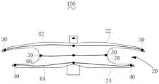
请参阅图1,一实施方式的封堵器100,包括封堵框架20及多个第一标记结构30、多个第二标记结构40和多个第三标记结构50。在一实施方式中,封堵框架20为由多根丝线编织而成的网状结构。丝线的材质可以为在生物体内不可腐蚀的金属,例如,丝线可以为镍钛合金丝、钴铬合金丝或不锈钢丝等。或者,丝线的材质也可以为生物可降解材料。例如,生物可降解材料可以为聚消旋乳酸(PDLLA)、聚D-乳酸(PDLA)、聚L-乳酸(PLLA)、聚乙醇酸(PGA)、聚乳酸-羟基乙酸共聚物(PLGA)、聚羟基脂肪酸脂(PHA)、聚二氧环己酮(PDO)或聚己内酯(PCL)等。在一实施方式中,封堵框架20由3D打印形成。Referring to FIG. 1 , an
封堵框架20包括第一封堵单元22、第二封堵单元24和腰部26。腰部26的两端分别与第一封堵单元22和第二封堵单元24连接,形成两端大中间小的两盘一腰结构。在一实施方式中,第一封堵单元22、第二封堵单元24和腰部26为一体式结构。The
多个第一标记结构30设置于第一封堵单元22上,多个第二标记结构40设置于第二封堵单元24上,多个第三标记结构50设置于腰部26上。在医学影像设备的光影的至少一入射方向下,多个第一标记结构30的中心连线呈直线,多个第二标记结构40的中心连线呈直线,多个第三标记结构50的中心连线呈直线,并且,多个第一标记结构30、多个第二标记结构40和多个第三标记结构50在医学影像设备下的显影强度不同、显影大小不同和/或显影形状不同。A plurality of
需要说明的是,当第一标记结构30、第二标记结构40和第三标记结构50为规则形状时,上述中心是指几何中心。当第一标记结构30、第二标记结构40和第三标记结构50为不规则形状时,上述中心是指重心。但无论是规则形状还是不规则形状,由于第一标记结构30、第二标记结构40和第三标记结构50的表面积很小,可认为第一标记结构30、第二标记结构40和第三标记结构50的连线均穿过几何中心或重心。It should be noted that, when the
还需要说明的是,多个第一标记结构30、多个第二标记结构40和多个第三标记结构50在医学影像设备下的显影强度不同、显影大小和/或显影形状不同是指以下几种并列情况:It should also be noted that the difference in development intensity, development size and/or development shape of the plurality of
1、多个第一标记结构30、多个第二标记结构40和多个第三标记结构50在医学影像设备下的显影强度不同;1. The multiple
2、多个第一标记结构30、多个第二标记结构40和多个第三标记结构50在医学影像设备下的显影大小不同;2. The development sizes of the plurality of
3、多个第一标记结构30、多个第二标记结构40和多个第三标记结构50在医学影像设备下的显影形状不同;3. The developing shapes of the plurality of
4、多个第一标记结构30、多个第二标记结构40和多个第三标记结构50在医学影像设备下的显影强度不同,且显影大小不同;4. The multiple
5、多个第一标记结构30、多个第二标记结构40和多个第三标记结构50在医学影像设备下的显影强度不同,显影形状不同;5. The multiple
6、多个第一标记结构30、多个第二标记结构40和多个第三标记结构50在医学影像设备下的显影大小不同,且显影形状不同;6. The multiple
7、多个第一标记结构30、多个第二标记结构40和多个第三标记结构50在医学影像设备下的显影强度、显影大小和显影形状均不同。7. The multiple
在一实施方式中,显影强度不同是指辐射不透性不同或荧光强度不同。在一实施方式中,显影强度不同,使得在医学影像设备下,人眼可视的第一标记结构30、第二标记结构40和第三标记结构50的颜色不同。In one embodiment, the difference in development intensity refers to the difference in radiopacity or the difference in fluorescence intensity. In one embodiment, the developing intensities are different, so that the colors of the
显影大小不同是在医学影像设备下,人眼可视的第一标记结构30、第二标记结构40和第三标记结构50的覆盖面积不同。The difference in developing size is that under medical imaging equipment, the coverage areas of the
显影形状不同是指,例如,在一实施方式中,第一标记结构30为圆形、第二标记结构40为三角形、第三标记结构50为方形。在另一实施方式中,第一标记结构30、第二标记结构40和第三标记结构50的形状可以从月牙形、星形及其他规则形状或不规则形状中选择。Different developing shapes refer to, for example, in one embodiment, the
在一实施方式中,第一标记结构30、第二标记结构40和第三标记结构50的形状不同,并且,在医学影像设备下,人眼可视的第一标记结构30、第二标记结构40和第三标记结构50的颜色不同。In one embodiment, the shapes of the
在一实施方式中,第一标记结构30、第二标记结构40和第三标记结构50的材料为金属材料。例如,在一实施方式中,第一标记结构30、第二标记结构40和第三标记结构50的材料为金、钽、铂、钨、铱等生物体不可吸收的金属。In one embodiment, the materials of the
在另一实施方式中,第一标记结构30、第二标记结构40和第三标记结构50的材料为铁、镁等生物体可吸收金属。当丝线的材质也为生物可降解材料时,选用生物体可吸收金属制备第一标记结构30、第二标记结构40和第三标记结构50,使得封堵器100是完全可生物降解的,在完成封堵后,封堵器100完全降解,无任何金属残留,避免远期临床风险。In another embodiment, the materials of the
在一实施方式中,第一标记结构30、第二标记结构40和第三标记结构50的材料的密度不同,且第一标记结构30、第二标记结构40和第三标记结构50的厚度不同,使得第一标记结构30、第二标记结构40和第三标记结构50在医学影像设备下的显影强度不同。In one embodiment, the densities of the materials of the
当第一标记结构30、第二标记结构40和第三标记结构50的材料相同时,一标记结构30、第二标记结构40和第三标记结构50的厚度不同,亦能使第一标记结构30、第二标记结构40和第三标记结构50在医学影像设备下的显影强度不同。但为了足够的区分度,第一标记结构30、第二标记结构40和第三标记结构50需要具有足够的厚度差,如此第一标记结构30、第二标记结构40和第三标记结构50之一的厚度会比较大,从而会导致输送困难。因此,选用不同密度的材料制备第一标记结构30、第二标记结构40和第三标记结构50,利用不同密度的材料自身在医学影像设备下的显影强度不同,并结合合适的厚度差,以在医学影像设备下获得足够的区分度,但又使第一标记结构30、第二标记结构40和第三标记结构50中任一个的厚度不至于过大,不会导致输送困难。When the materials of the
在一实施方式中,当第一标记结构30、第二标记结构40和第三标记结构50的材料的密度不同时,第一标记结构30、第二标记结构40和第三标记结构50的之间的厚度差至少为80微米,以使在医学影像设备下,第一标记结构30、第二标记结构40和第三标记结构50的所呈现的影像具有足够的色差,以使人眼能够区分。并且,第一标记结构30、第二标记结构40和第三标记结构50中的任一个的最小厚度为70微米。In one embodiment, when the densities of the materials of the
需要说明的是,第一标记结构30、第二标记结构40和第三标记结构50的之间的厚度差至少为80微米是指第一标记结构30、第二标记结构40和第三标记结构50中,两两均存在厚度差,且两两的厚度差至少为80微米。例如,第一标记结构30的厚度比第二标记结构40的厚度大至少80微米,第二标记结构40的厚度比第三标记结构50的厚度至少大80微米。又如,第一标记结构30的厚度比第三标记结构40的厚度大至少80微米,第二标记结构40的厚度比第三标记结构50的厚度至少大80微米,且,第一标记结构30和第二标记结构40的厚度差至少为80微米。It should be noted that the thickness difference between the
设置第一标记结构30、第二标记结构40和第三标记结构50中的任一个的最小厚度为70微米,以保证第一标记结构30、第二标记结构40和第三标记结构50具有足够的清晰度,使得第一标记结构30、第二标记结构40和第三标记结构50的可视性较好;同时,使当第一标记结构30、第二标记结构40和第三标记结构50的材料相同时,第一标记结构30、第二标记结构40和第三标记结构50的之间的厚度差至少为80微米,以获得足够的区分度。最小厚度在70微米范围内及最小厚度差为80微米的组合,获得可视性、可视性区分度及合理的厚度,避免增加封堵器100的整体的柔顺性而增加输送的难度。The minimum thickness of any one of the
在一实施方式中,第一标记结构30与第三标记结构50的厚度差至少为80微米,第二标记结构40的厚度与第一标记结构30的厚度相等。由于在轴向上,第一标记结构30与第三标记结构50相邻,第二标记结构40与第三标记结构50相邻,而第一标记结构30和第二标记结构40间隔设置,仅使第一标记结构30与第三标记结构50之间形成厚度差,第二标记结构40与第三标记结构50之间形成厚度差,而第一标记结构30和第二标记结构40不形成厚度差,亦能保证在医学影像设备下,能够识别和区分第一封堵单元22、第二封堵单元24和腰部26,并且,第一标记结构30、第二标记结构40和第三标记结构50中任一个的厚度不至于过大而影响输送。In one embodiment, the thickness difference between the
在一实施方式中,第一标记结构30、第二标记结构40和第三标记结构50的厚度相同,且第一标记结构30的材料、第二标记结构40的材料和第三标记结构50的材料的密度不同,使得第一标记结构30、第二标记结构40和第三标记结构50在医学影像设备下的显影强度不同。例如,在DSA影像设备下,密度较大的金属呈现亮黑色,密度较小的金属呈现灰色,由此可区分不同的标记结构,从而区分封堵框架20的不同部位。In one embodiment, the thicknesses of the
在一实施方式中,当第一标记结构30、第二标记结构40和第三标记结构50的厚度相同,且第一标记结构30的材料、第二标记结构40的材料和第三标记结构50的材料的密度不同时,第一标记结构30、第二标记结构40和第三标记结构50的表面积大小差异至少为0.2mm2,以进一步使在医学影像设备下,第一标记结构30、第二标记结构40和第三标记结构50的所呈现的影像具有足够区分度,以使人眼能够区分。并且,第一标记结构30、第二标记结构40和第三标记结构50的中的任一个的表面积的至少为0.2mm2。In one embodiment, when the thicknesses of the
当第一标记结构30、第二标记结构40和第三标记结构50的表面积过大时,所匹配的输送鞘管的尺寸需要越大。因此,第一标记结构30、第二标记结构40和第三标记结构50的表面积应该控制在一定的范围内。但当第一标记结构30、第二标记结构40和第三标记结构50的表面积过小时,对封堵器100形态的指示效果不佳。因此,在一实施方式中,第一标记结构30、第二标记结构40和第三标记结构50的中的任一个的表面积至少为0.2mm2,并且第一标记结构30、第二标记结构40和第三标记结构50的表面积大小差异至少为0.2mm2,以获得较优的可视性及可视性区分度,且可以使用尺寸较小的输送鞘管进行输送。When the surface area of the
需要说明的是,第一标记结构30、第二标记结构40和第三标记结构50的表面积大小差异至少为0.2mm2是指无论第一标记结构30、第二标记结构40和第三标记结构50分别为何种形状,无论三者的形状是否相同,第一标记结构30、第二标记结构40和第三标记结构50的面积大小差异至少为0.2mm2。并且,第一标记结构30、第二标记结构40和第三标记结构50中,两两均存在表面积差,且两两的表面积差至少为0.2mm2。It should be noted that the difference between the surface areas of the
在一实施方式中,多个第一标记结构30、多个第二标记结构40和多个第三标记结构50在医学影像设备下的显影强度不同,并且,多个第一标记结构30、多个第二标记结构40和多个第三标记结构50的显影形状也不同,如此,能够更显著地区分封堵框架20的不同部位,有利于术者准确无误地识别封堵器100的释放形态,提高手术的成功率。In one embodiment, the plurality of
上述封堵器100的多个第一标记结构30、多个第二标记结构40和多个第三标记结构50分别设置于封堵框架20的第一封堵单元22、第二封堵单元24和腰部26上,多个第一标记结构30、多个第二标记结构40和多个第三标记结构50在医学影像设备下的显影强度不同、显影大小不同或显影形状不同,从而可以通过医学影像设备识别封堵框架20的第一封堵单元22、第二封堵单元24和腰部26。The plurality of
并且,在医学影像设备的光影的至少一个入射方向下,多个第一标记结构30的中心连线呈直线,多个第二标记结构40的中心连线呈直线,多个第三标记结构50的中心连线呈直线时,指示封堵器在缺损部位成型良好。因而,能够在手术过程中判断上述封堵器100的释放形态是否良好。In addition, in at least one incident direction of light and shadow of the medical imaging device, the center connecting lines of the plurality of
在一实施方式中,多个第一标记结构30、多个第二标记结构40和多个第三标记结构50直接设置于封堵框架20上。例如,多个第一标记结构30缠绕于第一封堵单元22的丝线上,多个第二标记结构40缠绕于第二封堵单元24的丝线上,多个第三标记结构50缠绕于腰部26的丝线上。In one embodiment, a plurality of
在一实施方式中,封堵器100还包括第一阻流膜62、第二阻流膜64和第三阻流膜66,第一阻流膜62设置于第一封堵单元22上,第二阻流膜64设置于第二封堵单元24上,第三阻流膜66设置于腰部26上。设置第一阻流膜62、第二阻流膜64和第三阻流膜66,有利于避免残余分流,提高即时封堵性。In one embodiment, the
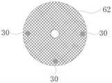
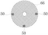
在一实施方式中,请一并参阅图1、图2a和图2b,多个第一标记结构30设置于第一阻流膜62上。请一并参阅图1、图3a和图3b多个第二标记结构40设置于第二阻流膜64上。请一并参阅图1、图4a和图4b,多个第三标记结构50设置于第三阻流膜66上。如此,多个第一标记结构30、多个第二标记结构40和多个第三标记结构50不仅仅能够指示第一封堵单元22、第二封堵单元24和腰部26的释放形态,还能指示第一阻流膜62、第二阻流膜64和第三阻流膜66的形态。例如,指示第一阻流膜62、第二阻流膜64和第三阻流膜66展开良好,无卷边现象。In one embodiment, please refer to FIG. 1 , FIG. 2 a and FIG. 2 b together, a plurality of
在一实施方式中,如图2a所示,第一标记结构30设置于第一阻流膜62的表面。如图3a所示,第二标记结构40设置于第二阻流膜64的表面。如图4a所示,第三标记结构50设置于第三阻流膜66的表面。可以采用粘结等固定方式分别将第一标记结构30、第二标记结构40和第三标记结构50固定于第一阻流膜62、第二阻流膜64和第三阻流膜66上。In one embodiment, as shown in FIG. 2 a , the
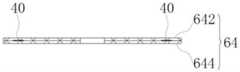
在一实施方式中,请再次参阅图2b,第一阻流膜62包括层叠设置的第一上层膜622和第一下层膜624,多个第一标记结构30设置于第一上层膜622和第一下层膜644之间。请再次参阅图3b,第二阻流膜64包括层叠设置的第二上层膜642和第二下层膜644,多个第二标记结构40设置于第二上层膜642和第二下层膜644之间。请再次参阅图4b,第三阻流膜66包括层叠设置的第三上层膜662和第三下层膜664,多个第三标记结构50设置于第三上层膜662和第三下层膜664之间。在一实施方式中,采用热熔焊接的方式将第一标记结构30固定于第一上层膜622和/或第一下层膜624上,将第二标记结构40固定于第二上层膜642和/或第二下层膜644上,将第三标记结构50固定于第三上层膜662和/或第三下层膜664上。上述设置方式能够防止第一标记结构30、第二标记结构40和/或第三标记结构50脱落。一方面,能够避免在输送过程中第一标记结构30、第二标记结构40和/或第三标记结构50脱落于输送鞘管中而使得封堵器100在医学影像设备下不可视或可视性较差,从而增加手术难度或导致手术不能进行;另一方面,避免在植入后,在内皮化前第一标记结构30、第二标记结构40和/或第三标记结构50脱落而引起不可控的风险。In one embodiment, please refer to FIG. 2b again, the
在一实施方式中,第一阻流膜62、第二阻流膜64和第三阻流膜66均为单层结构,多个第一标记结构30、多个第二标记结构40和多个第三标记结构50分别设置于第一阻流膜62、第二阻流膜64和第三阻流膜66的内部或表面。In one embodiment, the
当第一阻流膜62、第二阻流膜64和第三阻流膜66的厚度大于0.6毫米时,厚度过大,导致所需要的输送鞘管的尺寸较大,从而影响输送。当厚度小于0.02毫米时,阻流膜易破碎,例如在装载时,容易因拉伸而破碎。因此,在一实施方式中,无论第一阻流膜62、第二阻流膜64和第三阻流膜66之一或全部均为单层结构或双层结构,第一阻流膜62、第二阻流膜64和第三阻流膜66的厚度均在0.02~0.6毫米范围内。When the thickness of the
在一实施方式中,当将封堵器100处于拉伸状态或部分拉伸状态(如图5所示)时,第一阻流膜62的中心向靠近封堵器100的远端101方向延伸,且第一阻流膜62的边缘收缩而形成第一袋状结构,第一标记结构30位于第一袋状结构的内部。第二阻流膜64的中心向靠近封堵器100的远端方向101延伸,且第二阻流膜64的边缘收缩而形成第二袋状结构,第二标记结构40位于第二袋状结构的内部。第三阻流膜66的中心向靠近封堵器100的远端101方向延伸,且第三阻流膜66的边缘收缩而形成第三袋状结构,第三标记结构50位于第三袋状结构的内部。在另外的实施方式中,第一阻流膜62的中心向靠近封堵器100的近端102方向延伸且边缘收缩,第二阻流膜64的中心向靠近封堵器100的近端102方向延伸且边缘收缩,第三阻流膜66的中心向靠近封堵器100的近端102方向延伸且边缘收缩。In one embodiment, when the
请一并参阅图5和图6,当封堵器100装载于输送鞘管200中时,封堵器100处于拉伸状态。第一标记结构30、第二标记结构40和第三标记结构50分别位于相应的袋状结构的内部,能够避免与输送鞘管200直接接触,从而避免第一标记结构30、第二标记结构40和第三标记结构50与输送鞘管200的内壁发生摩擦、剐蹭而导致第一标记结构30、第二标记结构40和第三标记结构50脱落的现象。Please refer to FIG. 5 and FIG. 6 together. When the
在一实施方式中,采用缝线缝合的方式分别将第一阻流膜62、第二阻流膜64和第三阻流膜66设置于第一封堵单元22、第二封堵单元24和腰部26上。In one embodiment, the
在一实施方式中,通过采用合理的缝合方式使得在拉伸状态,第一标记结构30、第二标记结构40和第三标记结构50分别位于相应的袋状结构的内部。例如,如图5所示,通过采用第一缝合线71和第二缝合线72将第一阻流膜62固定于第一封堵单元22内部。第一缝合线71比第二缝合线72更靠近第一阻流膜62的中心。第二阻流膜64和第三阻流膜66的固定方式相同,此处不再赘述。In one embodiment, the
在一实施方式中,每个第一标记结构30的边缘至第一阻流膜62的边缘的距离为0~2毫米。每个第二标记结构40的边缘至第二阻流膜64的边缘的距离为0~2毫米。每个第三标记结构50的边缘至第三阻流膜66的边缘的距离为0~2毫米。设置上述三个距离分别为0~2毫米,有利于识别第一封堵单元22、第二封堵单元24和腰部26的极限位置,从而有利于封堵器100的准确定位。In one embodiment, the distance from the edge of each
在一实施方式中,每个第一标记结构30的边缘至第一阻流膜62的边缘的距离为1~2毫米。每个第二标记结构40的边缘至第二阻流膜64的边缘的距离为1~2毫米。每个第三标记结构50的边缘至第三阻流膜66的边缘的距离为1~2毫米。如此,不仅仅利于封堵器100的准确定位,还有利于避免第一标记结构30、第二标记结构40和/第三标记结构50在装载或输送过程中易与输送鞘管的内壁剐蹭而脱落。In one embodiment, the distance from the edge of each
在一实施方式中,第一标记结构30的数量至少为3个,且在自然状态下,所述至少3个第一标记结构30不在同一直线上。第二标记结构40的数量至少为3个,且在自然状态下,至少3个第二标记结构40不在同一直线上。第三标记结构50的数量至少为3个,且在自然状态下,至少3个第三标记结构50不在同一直线上。如此设置,避免在医学影像设备下,多个第一标记结构30重叠为一个点,多个第二标记结构40重叠为一个点及多个第三标记结构50重叠为一个点而影响封堵器100的整体形态的可视性的判断,有利于手术顺利进行。In one embodiment, the number of the
当标记结构的数量过多时,一方面增加成本,另一方面如果标记结构由生物体不可吸收的材料制成,会导致过多的异物留存而可能产生远期临床风险,也会影响输送性能。因此,在一实施方式中,第一标记结构30的数量为3~12个,第二标记结构40的数量为3~12个,第三标记结构50的数量为3~12个。When the number of marker structures is too large, on the one hand, the cost will be increased. On the other hand, if the marker structures are made of non-absorbable materials, it will lead to excessive retention of foreign bodies, which may cause long-term clinical risks, and also affect the delivery performance. Therefore, in one embodiment, the number of the
在一实施方式中,至少3个第一标记结构30均匀分布,至少3个第二标记结构40均匀分布,至少3个第三标记结构50均匀分布。以第一标记结构30为例,均匀分布是指,多个第一标记结构30的中心连线成正多边形或任意相邻两个第一标记结构30的距离相等。多个第二标记结构40均匀分布和多个第三标记结构50均匀分布具有相同的含义,此处不在赘述。In one embodiment, at least three first marking
在一实施方式中,第一标记结构30的数量为三个,三个第一标记结构30的中心连线成正三角形。第二标记结构40的数量为三个,三个第二标记结构40的中心连线成正三角形。第三标记结构50的数量为三个,三个第三标记结构50的中心连线成正三角形。如此设置,使用最少数量的第一标记结构30、最少数量的第二标记结构40和最少数量的第三标记结构50,能够避免过多的非生物可吸收的异物残留及避免对封堵器100的输送性能产生不利影响。并且,无论医学影像设备的光源的入射方向如何,投影形态均不变,均可以通过标记结构的位置和标记结构之间的长度判断封堵器100的形态。同时,方便操作,对医学影像设备的光影的入射方向不做过多的强制要求,有利于缩短手术时间。In one embodiment, the number of the
进一步地,在手术过程中,当第一封堵单元22释放时,可能会有第一封堵单元22或第二封堵单元24的一部分盘面卡在缺损部位的现象发生,按上述方式设置,不论哪个部位受到挤压,都可以通过标记结构的位置和标记结构之间的长度判断封堵器100的形态。Further, during the operation, when the
在一实施方式中,第一标记结构30的数量为三个,三个第一标记结构30的连线成三角形。并且,其中两个第一标记结构30的中心连线穿过第一阻流膜62的中心,或两个第一标记结构30的中心连线穿过第一封堵单元22的中心。第二标记结构40的数量为三个,三个第二标记结构40的中心连线成三角形。并且,其中两个第二标记结构40的中心连线穿过第二阻流膜64的中心,或两个第二标记结构40的中心连线穿过第二封堵单元24的中心。第三标记结构50的数量为三个,三个第三标记结构50的中心连线成三角形。并且,其中两个第三标记结构50的中心连线穿过第三阻流膜66的中心,或两个第三标记结构50的中心连线穿过腰部26的中心。如此设置,以第一标记结构30为例,在医学影像设备的光影的某一入射方向下,三个第一标记结构30的连线(穿过中心)的长度与第一阻流膜62的宽度(例如,当第一阻流膜62为圆形时,宽度为直径。当第一阻流膜62为椭圆形时,宽度为长轴的长度)的差值为0~2毫米。如此,进一步利于至少封堵框架20的各个部位的边缘形态。In one embodiment, the number of the
在一实施方式中,第一标记结构30的数量为2个,且两个第一标记结构30的中心连线穿过第一阻流膜62的中心,或两个第一标记结构30的中心连线穿过第一封堵单元22的中心。第二标记结构40的数量为2个,两个第二标记结构40的中心连线穿过第二阻流膜64的中心,或两个第二标记结构40的中心连线穿过第二封堵单元24的中心。第三标记结构50的数量为2个,两个第三标记结构50的中心连线穿过第三阻流膜66的中心,或两个第三标记结构50的中心连线穿过腰部26的中心。In one embodiment, the number of the
在一实施方式中,多个第一标记结构30设置于第一阻流膜62上。多个第二标记结构40设置于第二阻流膜64上。多个第三标记结构50直接设置于腰部26上。并且,多个第三标记结构50缠绕于腰部26的丝线上,并且,多个第三标记结构50沿腰部26的周向设置,且多个第三标记结构50位于同一平面上。如此,不仅能够较好地区分第一封堵单元22、第二封堵单元24和腰部,还有利于提高腰部26的支撑性能,使得在血流的冲击下,能够避免封堵器20移位。In one embodiment, the plurality of
请再次参阅图5,在一实施方式中,封堵器100还包括远端封头80和设置于远端封头80上的远端标记结构90。远端封头80与第一封堵单元22相连,用于固定第一封堵单元22的丝线的自由端。Referring to FIG. 5 again, in one embodiment, the
在封堵器100的自然状态下,至少两个第一标记结构30与远端标记结构90的连线呈三角形。在手术过程中,该三角形的高度会不断变小而使至少两个第一标记结构30与远端标记结构90的连线变成一直线,当变成直线时即表示封堵器100与缺损部位的贴壁良好,可以停止牵拉操作而继续释放封堵器100的第二封堵单元24。设置远端标记结构90有利于进一步提高手术操作的便利性。In the natural state of the
远端标记结构90与第一标记结构30在医学影像设备下的显影强度不同、显影大小和/或显影形状不同。显影强度不同、显影大小和显影形状不同的实现方式与上述相同,此处不在赘述。The
远端标记结构90与第一标记结构30在医学影像设备下的显影强度不同和/或显影形状不同,使得在手术过程中,能够区分远端标记结构90和第一标记结构30,有利于判断两个第一标记结构30与远端标记结构90的连线所成三角形的高度变化,使手术顺利进行。The
以上所述实施例的各技术特征可以进行任意的组合,为使描述简洁,未对上述实施例中的各个技术特征所有可能的组合都进行描述,然而,只要这些技术特征的组合不存在矛盾,都应当认为是本说明书记载的范围。The technical features of the above-described embodiments can be combined arbitrarily. For the sake of brevity, all possible combinations of the technical features in the above-described embodiments are not described. However, as long as there is no contradiction between the combinations of these technical features, All should be regarded as the scope described in this specification.
以上所述实施例仅表达了本发明的几种实施方式,其描述较为具体和详细,但并不能因此而理解为对发明专利范围的限制。应当指出的是,对于本领域的普通技术人员来说,在不脱离本发明构思的前提下,还可以做出若干变形和改进,这些都属于本发明的保护范围。因此,本发明专利的保护范围应以所附权利要求为准。The above-mentioned embodiments only represent several embodiments of the present invention, and the descriptions thereof are specific and detailed, but should not be construed as a limitation on the scope of the invention patent. It should be pointed out that for those of ordinary skill in the art, without departing from the concept of the present invention, several modifications and improvements can also be made, which all belong to the protection scope of the present invention. Therefore, the protection scope of the patent of the present invention should be subject to the appended claims.
Claims (10)
Translated fromChinesePriority Applications (1)
| Application Number | Priority Date | Filing Date | Title |
|---|---|---|---|
| CN201911073105.9ACN112773417B (en) | 2019-11-05 | 2019-11-05 | Plugging device |
Applications Claiming Priority (1)
| Application Number | Priority Date | Filing Date | Title |
|---|---|---|---|
| CN201911073105.9ACN112773417B (en) | 2019-11-05 | 2019-11-05 | Plugging device |
Publications (2)
| Publication Number | Publication Date |
|---|---|
| CN112773417A CN112773417A (en) | 2021-05-11 |
| CN112773417Btrue CN112773417B (en) | 2022-09-02 |
Family
ID=75747512
Family Applications (1)
| Application Number | Title | Priority Date | Filing Date |
|---|---|---|---|
| CN201911073105.9AActiveCN112773417B (en) | 2019-11-05 | 2019-11-05 | Plugging device |
Country Status (1)
| Country | Link |
|---|---|
| CN (1) | CN112773417B (en) |
Families Citing this family (2)
| Publication number | Priority date | Publication date | Assignee | Title |
|---|---|---|---|---|
| CN113616266B (en)* | 2021-08-26 | 2022-09-30 | 四川大学 | An absorbable occluder |
| CN115770082A (en)* | 2022-11-21 | 2023-03-10 | 深圳市创科医疗科技有限公司 | Plugging device |
Citations (4)
| Publication number | Priority date | Publication date | Assignee | Title |
|---|---|---|---|---|
| CN109464168A (en)* | 2018-12-17 | 2019-03-15 | 先健科技(深圳)有限公司 | occluder |
| CN109498210A (en)* | 2018-11-08 | 2019-03-22 | 东莞先健畅通医疗有限公司 | Intraluminal stent |
| CN109700487A (en)* | 2018-12-29 | 2019-05-03 | 先健科技(深圳)有限公司 | Conveyer and transportation system |
| CN109770964A (en)* | 2018-12-11 | 2019-05-21 | 先健科技(深圳)有限公司 | Occluder and preparation method thereof |
- 2019
- 2019-11-05CNCN201911073105.9Apatent/CN112773417B/enactiveActive
Patent Citations (4)
| Publication number | Priority date | Publication date | Assignee | Title |
|---|---|---|---|---|
| CN109498210A (en)* | 2018-11-08 | 2019-03-22 | 东莞先健畅通医疗有限公司 | Intraluminal stent |
| CN109770964A (en)* | 2018-12-11 | 2019-05-21 | 先健科技(深圳)有限公司 | Occluder and preparation method thereof |
| CN109464168A (en)* | 2018-12-17 | 2019-03-15 | 先健科技(深圳)有限公司 | occluder |
| CN109700487A (en)* | 2018-12-29 | 2019-05-03 | 先健科技(深圳)有限公司 | Conveyer and transportation system |
Also Published As
| Publication number | Publication date |
|---|---|
| CN112773417A (en) | 2021-05-11 |
Similar Documents
| Publication | Publication Date | Title |
|---|---|---|
| US12414775B1 (en) | Occlusion device | |
| Chue et al. | The role of echocardiography in percutaneous left atrial appendage occlusion | |
| CN204016366U (en) | A kind of degradable stopper | |
| CN112773417B (en) | Plugging device | |
| CN111956275A (en) | Plugging device | |
| Zhu et al. | Animal experimental study of the fully biodegradable atrial septal defect (ASD) occluder | |
| CN205251616U (en) | Can absorb plugging device | |
| CN109770964B (en) | Plugging device and preparation method thereof | |
| WO2020093927A1 (en) | Endoluminal stent | |
| CN114767179B (en) | A kind of atrial septal defect occluder | |
| CN209611205U (en) | Plugging device | |
| WO2017113532A1 (en) | Imageable and degradable occluder | |
| CN111150433B (en) | Occluder | |
| WO2020093926A1 (en) | Occlusion device | |
| CN209611204U (en) | Plugging device | |
| Guarracini et al. | Appropriate use criteria of left atrial appendage closure devices: latest evidences | |
| CN212346592U (en) | Plugging device | |
| CN114795309A (en) | Plugging device | |
| Faletra et al. | Atrial Interventions | |
| CN114052815A (en) | occluder | |
| CN112022234B (en) | Implantable device and method of making the same | |
| Valgimigli | Atrial Interventions | |
| CN206120365U (en) | Can survey plugging device of atrial septal defect size | |
| CN109770965B (en) | A kind of blocking film and its manufacturing method and occluder | |
| Zavalloni | PFO Closure: Techniques and Devices |
Legal Events
| Date | Code | Title | Description |
|---|---|---|---|
| PB01 | Publication | ||
| PB01 | Publication | ||
| SE01 | Entry into force of request for substantive examination | ||
| SE01 | Entry into force of request for substantive examination | ||
| GR01 | Patent grant | ||
| GR01 | Patent grant |