CN112773060B - Wrist strap and wrist watch - Google Patents
Wrist strap and wrist watchDownload PDFInfo
- Publication number
- CN112773060B CN112773060BCN202011594117.9ACN202011594117ACN112773060BCN 112773060 BCN112773060 BCN 112773060BCN 202011594117 ACN202011594117 ACN 202011594117ACN 112773060 BCN112773060 BCN 112773060B
- Authority
- CN
- China
- Prior art keywords
- wristband
- inflatable
- bag
- wearing
- main body
- Prior art date
- Legal status (The legal status is an assumption and is not a legal conclusion. Google has not performed a legal analysis and makes no representation as to the accuracy of the status listed.)
- Active
Links
Images


Classifications
- A—HUMAN NECESSITIES
- A44—HABERDASHERY; JEWELLERY
- A44C—PERSONAL ADORNMENTS, e.g. JEWELLERY; COINS
- A44C5/00—Bracelets; Wrist-watch straps; Fastenings for bracelets or wrist-watch straps
- A44C5/0053—Flexible straps
- A—HUMAN NECESSITIES
- A44—HABERDASHERY; JEWELLERY
- A44C—PERSONAL ADORNMENTS, e.g. JEWELLERY; COINS
- A44C5/00—Bracelets; Wrist-watch straps; Fastenings for bracelets or wrist-watch straps
- A44C5/0053—Flexible straps
- A44C5/0069—Flexible straps extensible
- A—HUMAN NECESSITIES
- A44—HABERDASHERY; JEWELLERY
- A44C—PERSONAL ADORNMENTS, e.g. JEWELLERY; COINS
- A44C5/00—Bracelets; Wrist-watch straps; Fastenings for bracelets or wrist-watch straps
Landscapes
- Professional, Industrial, Or Sporting Protective Garments (AREA)
Abstract
Translated fromChinese
Description
Translated fromChinese技术领域technical field
本发明涉及显示技术领域,特别是涉及一种腕带及腕表。The invention relates to the field of display technology, in particular to a wristband and a watch.
背景技术Background technique
随着科技不断发展进步,各种腕表越来越受欢迎,尤其对于智能腕表,既能够满足佩戴人员对时间的获取,同时还能够为佩戴人员提供一些身体条件信息等参数反馈,被越来越多的用户所青睐,相应的,对于腕表的体验度要求也就越来越高。With the continuous development and progress of science and technology, all kinds of watches are becoming more and more popular, especially for smart watches, which can not only satisfy the wearer's acquisition of time, but also provide the wearer with some physical condition information and other parameter feedback. It is favored by more and more users, and correspondingly, the experience requirements for watches are getting higher and higher.
例如,佩戴人员处于不同的状态时对腕表的腕带松弛程度需求是有差异的。当佩戴人员处于运动状态时,其对腕带的需求需要更紧一些,避免在运动时腕带随意晃动造成不适。而当佩戴人员在非运动状态下,其对腕带的需求相对运动时更松弛一些较为舒适。For example, when the wearer is in different states, there are different requirements for the degree of slack in the wrist strap of the watch. When the wearer is exercising, the demand for the wrist strap needs to be tighter, so as to avoid discomfort caused by the random shaking of the wrist strap during exercise. And when the wearer is in a non-exercising state, his demand for the wristband is more relaxed and more comfortable than when he is exercising.
已有的腕带,为满足佩戴人员对于不同状态下对腕带松弛度的要求,主要是通过调节包围佩戴人员手腕等位置的长短来调节,操作复杂,且不利于腕带松弛度的调节。In order to meet the requirements of the wearer for the slackness of the wristband under different conditions, the existing wristbands are mainly adjusted by adjusting the length of the position surrounding the wearer's wrist, which is complicated to operate and is not conducive to the adjustment of the slackness of the wristband.
发明内容Contents of the invention
本发明实施例提供一种腕带及腕表,腕带能够根据佩戴人员的运动状态调节松弛度,操作简便,利于腕带松弛度的调节。Embodiments of the present invention provide a wristband and a wrist watch. The wristband can adjust the slackness according to the movement state of the wearer, and is easy to operate, which is beneficial to the adjustment of the slackness of the wristband.
一方面,根据本发明实施例提出了一种腕带,包括:腕带主体,用于套设于佩戴体,腕带主体包括带本体以及设置于带本体的充气囊,围合形成充气囊的壁部设置有与充气囊的内腔连通的释放结构,以释放充气囊内的气体;充气装置,设置于腕带主体,充气装置包括充气部件及驱动部件,充气部件与充气囊连通,驱动部件与佩戴体随动并向充气部件提供动力,以对充气囊充气。On the one hand, according to the embodiment of the present invention, a wristband is proposed, including: a wristband main body, which is used to be sleeved on a wearing body. The wristband main body includes a belt body and an inflatable bag arranged on the belt body. The wall is provided with a release structure communicating with the inner cavity of the inflatable bag to release the gas in the inflatable bag; the inflatable device is arranged on the main body of the wristband, and the inflatable device includes an inflatable part and a driving part, the inflatable part communicates with the inflatable bag, and the driving part It moves with the wearing body and provides power to the inflatable part to inflate the inflatable bag.
另一方面,根据本发明实施例提出了一种腕表,包括上述的腕带;表盘,与腕带连接并能够与腕带共同围合形成封闭环,漏气孔朝向封闭环设置。On the other hand, according to an embodiment of the present invention, a wrist watch is proposed, including the above-mentioned wrist strap; the dial is connected with the wrist strap and can be enclosed with the wrist strap to form a closed ring, and the air leakage hole is set toward the closed ring.
根据本发明实施例提供的腕带以及腕表,其腕带包括腕带主体以及充气装置,腕带主体具有带本体以及设置于带本体的充气囊,充气装置包括充气部件以及驱动部件,当腕带用于腕表并设置于佩戴体上时,腕带会根据佩戴者的状态调节其对于佩戴体的松弛度。如当佩戴者运动时,驱动部件将会随动并向充气部件提供动力,以对充气囊充气,使得充气囊体积变大,保证腕带在佩戴者的腕部更加紧致,当佩戴者处于安静状态时,可以利用与充气囊的内腔连通的释放结构将充气囊内部的气体释放,以调松腕带,操作简便,利于腕带松弛度的调节。According to the wristband and the wrist watch provided by the embodiment of the present invention, the wristband includes a wristband main body and an inflation device. When the wristband is used for a watch and is set on the wearing body, the wristband will adjust its slack to the wearing body according to the state of the wearer. For example, when the wearer moves, the driving part will follow and provide power to the inflatable part to inflate the inflatable bag, so that the volume of the inflatable bag becomes larger and ensures that the wristband is tighter on the wearer's wrist. In the quiet state, the release structure connected with the inner cavity of the air bag can be used to release the gas inside the air bag to loosen the wrist strap, which is easy to operate and facilitates the adjustment of the slack of the wrist strap.
附图说明Description of drawings
下面将参考附图来描述本发明示例性实施例的特征、优点和技术效果。The features, advantages, and technical effects of exemplary embodiments of the present invention will be described below with reference to the accompanying drawings.
图1是本发明一个实施例的腕带的整体结构示意图;Fig. 1 is a schematic diagram of the overall structure of a wristband according to an embodiment of the present invention;
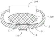
图2是本发明一个实施例的腕带处于松弛状态下的使用状态图;Fig. 2 is a use state diagram of the wristband in a relaxed state according to an embodiment of the present invention;
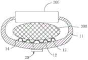
图3是本发明一个实施例的腕带处于调紧状态下的使用状态图;Fig. 3 is a diagram of the use state of the wristband in the tightened state according to an embodiment of the present invention;
图4是本发明一个实施例的腕带的俯视图Fig. 4 is the top view of the wristband of an embodiment of the present invention
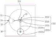
图5是本发明一个实施例的充气装置与安装框架的结构示意图;Fig. 5 is a schematic structural view of an inflatable device and a mounting frame according to an embodiment of the present invention;
图6是图1中A处放大图;Fig. 6 is an enlarged view of place A in Fig. 1;
图7是本发明另一个实施例的腕带的局部结构示意图;Fig. 7 is a schematic diagram of a partial structure of a wristband according to another embodiment of the present invention;
图8是本发明又一个实施例的腕带处于松弛状态下的使用状态图;Fig. 8 is a diagram of the use state of the wristband in a relaxed state according to another embodiment of the present invention;
图9是本发明又一个实施例的腕带处于调紧状态下的使用状态图;Fig. 9 is a diagram of the use state of the wristband in a tightened state according to another embodiment of the present invention;
图10是本发明再一个实施例的腕带处于松弛状态下的使用状态图;Fig. 10 is a diagram of the use state of the wristband in a relaxed state according to another embodiment of the present invention;
图11是本发明再一个实施例的腕带处于调紧状态下的使用状态图;Fig. 11 is a diagram of the use state of the wristband in a tightened state according to another embodiment of the present invention;
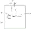
图12是本发明另一个实施例的充气装置与安装框架配合的结构示意图;Fig. 12 is a structural schematic view of the cooperation between the inflator and the installation frame according to another embodiment of the present invention;
图13是本发明又一个实施例的充气装置与安装框架配合的结构示意图;Fig. 13 is a structural schematic diagram of the cooperation between the inflator and the installation frame according to another embodiment of the present invention;
图14是本发明再一个实施例的充气装置与安装框架配合的结构示意图;Fig. 14 is a structural schematic view of the cooperation between the inflator and the installation frame according to another embodiment of the present invention;
图15是本发明再一个实施例的腕带的结构示意图;Fig. 15 is a structural schematic diagram of a wristband according to another embodiment of the present invention;
图16是本发明一个实施例的腕表的结构示意图;Fig. 16 is a structural schematic diagram of a wristwatch according to an embodiment of the present invention;
图17是图16所示结构的俯视图。FIG. 17 is a top view of the structure shown in FIG. 16 .
其中:in:
100-腕带;100 - wrist strap;
10-腕带主体;11-带本体;111-柔性部;112-刚性固定部;11a-第一分体;11b-第二分体;12-充气囊;13-释放结构;131-漏气孔;14-膜片体;10-wristband main body; 11-band body; 111-flexible part; 112-rigid fixed part; 11a-first split; 11b-second split; 12-inflatable bag; 13-release structure; 131-air leakage Hole; 14-diaphragm body;
20-充气装置;21-充气部件;22-驱动部件;221-转接件;222-运动件;2221-转盘;2222-摆动部;2222a-摆臂;2222b-摆锤;2223-第一转轴;2224-第二转轴;23-引导部件;24-连接管路;25-第二控制阀;20-inflatable device; 21-inflatable parts; 22-driving parts; 221-transition piece; 222-moving part; ; 2224-the second rotating shaft; 23-guiding components; 24-connecting pipeline; 25-the second control valve;
30-安装框架;30 - mounting frame;
40-安装座;40 - Mounting seat;
200-表盘;200 - dial;
300-佩戴体。300-wearing body.
在附图中,相同的部件使用相同的附图标记。附图并未按照实际的比例绘制。In the figures, the same parts are given the same reference numerals. The figures are not drawn to scale.
具体实施方式Detailed ways
下面将详细描述本发明的各个方面的特征和示例性实施例。在下面的详细描述中,提出了许多具体细节,以便提供对本发明的全面理解。但是,对于本领域技术人员来说很明显的是,本发明可以在不需要这些具体细节中的一些细节的情况下实施。下面对实施例的描述仅仅是为了通过示出本发明的示例来提供对本发明的更好的理解。在附图和下面的描述中,至少部分的公知结构和技术没有被示出,以便避免对本发明造成不必要的模糊;并且,为了清晰,可能夸大了部分结构的尺寸。此外,下文中所描述的特征、结构或特性可以以任何合适的方式结合在一个或更多实施例中。Features and exemplary embodiments of various aspects of the invention will be described in detail below. In the following detailed description, numerous specific details are set forth in order to provide a thorough understanding of the present invention. It will be apparent, however, to one skilled in the art that the present invention may be practiced without some of these specific details. The following description of the embodiments is only to provide a better understanding of the present invention by showing examples of the present invention. In the drawings and the following description, at least some well-known structures and techniques have not been shown in order to avoid unnecessarily obscuring the present invention; and, for clarity, the dimensions of some structures may have been exaggerated. Furthermore, the features, structures, or characteristics described hereinafter may be combined in any suitable manner in one or more embodiments.
下述描述中出现的方位词均为图中示出的方向,并不是对本发明的腕带以及腕表的具体结构进行限定。在本发明的描述中,还需要说明的是,除非另有明确的规定和限定,术语“安装”、“连接”应做广义理解,例如,可以是固定连接,也可以是可拆卸连接,或一体地连接;可以是直接相连,也可以间接相连。对于本领域的普通技术人员而言,可视具体情况理解上述术语在本发明中的具体含义。The orientation words appearing in the following descriptions are all directions shown in the figure, and are not intended to limit the specific structures of the wristband and wristwatch of the present invention. In the description of the present invention, it should also be noted that, unless otherwise clearly specified and limited, the terms "installation" and "connection" should be understood in a broad sense, for example, it can be a fixed connection or a detachable connection, or Connected integrally; either directly or indirectly. For those skilled in the art, the specific meanings of the above terms in the present invention can be understood according to specific situations.
随着腕表的不断普及,佩戴人员对于腕表的体验度要求越来越高,例如在不同运动状态下腕表的腕带的松弛度调节则为腕表选购时的一项重要指标。已有的腕表,其腕带的松紧调节形式大多采用锁扣的形式调节包围佩人员手腕等位置的长短来调节松紧度,该种方式操作复杂,不利于腕带松弛度的调节。也有部分腕表采用主动向腕带内部充气的方式实现腕带松弛度的调节,其主要通过气泵等动力源根据需要向腕带的内部输入气体或者将腕带内部的气体抽出来达到调节松弛度的目的,该种设置方式虽然能够满足松弛度的调节,但需要外配动力源,动力源的设置需要消耗一定的电能,并且需要配备相应的控制系统,使得腕带整体结构复杂且成本高。With the continuous popularization of wristwatches, wearers have higher and higher requirements for the experience of wristwatches. For example, the slack adjustment of wristbands of wristwatches in different sports states is an important indicator when purchasing wristwatches. Most of the existing wristwatches use locks to adjust the length of the wrist of the wearer to adjust the tightness of the wristband. This method is complicated to operate and is not conducive to the adjustment of the slackness of the wristband. There are also some watches that actively inflate the wristband to adjust the slack of the wristband. It mainly uses an air pump and other power sources to input gas into the wristband or pump out the gas inside the wristband to adjust the slack. Although this setting method can meet the adjustment of slack, it needs an external power source. The setting of the power source needs to consume a certain amount of electric energy, and it needs to be equipped with a corresponding control system, which makes the overall structure of the wristband complicated and expensive.
基于上述技术问题,本发明实施例提供了一种新的腕带,该腕带能够根据佩戴人员的运动状态调节松弛度,操作简便,利于腕带松弛度的调节。为了更好地理解本发明,下面结合图1至图17根据本发明实施例的腕带以及腕表进行详细描述。Based on the above technical problems, the embodiment of the present invention provides a new wrist strap, which can adjust the slack according to the movement state of the wearer, and is easy to operate, which is beneficial to the adjustment of the slack of the wrist strap. In order to better understand the present invention, the wristband and wristwatch according to the embodiment of the present invention will be described in detail below with reference to FIGS. 1 to 17 .
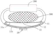
如图1至图5所示,图1示出了本发明一个实施例的腕带100的结构示意图,图2示出了本发明一个实施例的腕带100处于松弛状态下的使用状态图,图3示出了本发明一个实施例的腕带100处于调紧状态下的使用状态图,如图4以及图5所示,图4示出了本发明一个实施例的腕带100的俯视图,图5示出了本发明一个实施例的充气装置20与安装框架30配合的结构示意图。As shown in FIGS. 1 to 5 , FIG. 1 shows a schematic structural view of a
本发明实施例提供的腕带100包括腕带主体10以及充气装置20,腕带主体10用于套设于佩戴体300,腕带主体10包括带本体11以及设置于带本体11的充气囊12,围合形成充气囊12的壁部设置有与充气囊12的内腔连通的释放结构13,以释放充气囊12内的气体,充气装置20设置于腕带主体10,充气装置20包括充气部件21及驱动部件22,充气部件21与充气囊12连通,驱动部件22与佩戴体300随动并向充气部件21提供动力,以对充气囊12充气。The
本发明实施例提供的腕带100,当用于腕表并设置于佩戴体300上时,腕带100会根据佩戴体300的运动状态调节其对于佩戴体300的松弛度。当佩戴体300处于非运动状态时,可以利用与充气囊12的内腔连通的释放结构13将充气囊12内部的气体释放,以调松腕带100。如当佩戴者运动时,驱动部件22将会随动并向充气部件21提供动力,以对充气囊12充气,使得充气囊12体积变大,保证腕带100在佩戴者的腕部更加紧致,操作简便,利于腕带100松弛度的调节。When the
并且,本发明实施例提供的腕带100,其充气装置20的驱动部件22是利用与佩戴体300随动获取动能以向充气部件21提供动力,满足对充气囊12的充气需求,无需外配气泵等动力源,进而也无需配置相应的控制系统来控制动力源,腕带100整体结构简单且成本低廉。In addition, in the
一些可选地实施例中,本发明实施例提供的腕带100,其带本体11可以至少部分采用柔性带制成且柔性带在外力作用下具有预定的形变能力。可选地,带本体11可以全部采用柔性带制成,当然,在有些实施例中,带本体11可以仅在设置充气囊12的位置采用柔性带制成。In some optional embodiments, in the
作为一种可选地实施方式,腕带主体10在自身长度方向可以具有两个相对的自由端,在用于腕表时,两个相对的自由端可以用于与表盘200连接并共同围合形成封闭环。As an optional implementation, the wristband
作为一种可选地实施方式,本发明实施例提供的腕带100,充气囊12设置于带本体11的内部并将带本体11分隔形成相对设置的第一分体11a以及第二分体11b,在第一分体11a以及第二分体11b的排布方向上,第一分体11a的壁厚小于第二分体11b的壁厚,当用于腕表并设置于佩戴体300时,第一分体11a面向佩戴体300设置且第二分体11b背离佩戴体300设置。As an optional implementation mode, in the
如图2所示,腕带100的充气囊12在未充气的状态下,带本体11上形成的第一分体11a与佩戴体300之间可以形成有间隙,此时腕带100处于松弛状态。As shown in Figure 2, when the
如图3所示,当佩戴体300在运动时,如佩戴体300在跑步等运动的过程中,驱动部件22与佩戴体300随动并向充气部件21提供动力,以对充气囊12充气。当充气囊12中进入气体后,充气囊12的体积将变大,同时挤压第一分体11a以及第二分体11b,向第一分体11a以及第二分体11b提供向远离彼此方向运动的作用力。由于第一分体11a的壁厚小于第二分体11b的壁厚,故第一分体11a抵抗外力的能力弱于第二分体11b,充入的气体会预先向第一分体11a所在侧运动,第一分体11a将产生向远离第二分体11b的方向形变,以与佩戴体300接触,减小或者消除与佩戴体300之间的间隙,使得腕带100处于调紧状态,满足佩戴体300在由非运动状态下至运动状态下对腕带100的自动调紧需求。As shown in FIG. 3 , when the wearing
如图6所示,图6是图1中A处放大图。一些可选地实施例中,释放结构13包括漏气孔131,漏气孔131与充气囊12的内腔连通且面向佩戴体300设置。通过使得释放结构13包括漏气孔131,使得充气囊12内的气体可以缓慢的泄露,由于漏气孔131是面向佩戴体300设置的,因此,当佩戴体300处于运动状态下,充气装置20向充气囊12内充气使得充气囊12膨胀,漏气孔131暂时贴合于佩戴体300,保持腕带100的调紧状态。而当佩戴体300处于非运动状态时,驱动部件22也随之停止向充气部件21提供动力,充气囊12内的气体在漏气孔131的作用下将缓慢泄露,自动实现腕带100的调松。As shown in Fig. 6, Fig. 6 is an enlarged view of A in Fig. 1 . In some optional embodiments, the
在一些可选地实施例中,漏气孔131可以设置于第一分体11a并与充气囊12连通,漏气孔131的数量可以根据充气囊12的尺寸、漏气速率要求等参数设定,可以为一个,也可以为两个以上,当为两个以上时,可以在环绕佩戴体300的方向上间隔分布。In some optional embodiments, the air leakage holes 131 can be arranged on the
参见图4至图6,作为一种可选地实施方式,本发明各实施例提供的腕带100,其驱动部件22包括转动连接的转接件221以及运动件222,转接件221背离运动件222的一端与充气部件21连接,运动件222与佩戴体300随动并通过转接件221驱动充气部件21伸缩。驱动部件22采用上述形式,能够通过转接件221将运动件222与充气部件21连接,使得运动件222与佩戴体300随动产生的动能能够转换为充气部件21的伸缩运动,可靠的满足对充气囊12的充气需求。Referring to Fig. 4 to Fig. 6, as an optional implementation mode, in the
在一些可选地实施例中,本发明实施例提供的腕带100,运动件222可以与腕带主体10转动连接,运动件222与腕带主体10的转动中心和转接件221与运动件222的转动中心彼此间隔设置,运动件222与佩戴体300随动并相对腕带主体10转动,以通过转接件221驱动充气部件21伸缩。通过使得运动件222与腕带主体10之间转动连接,使得佩戴体300在运动时,运动件222可以与腕带主体10的转动中心为旋转中心相对腕带主体10做整周转动,以带动转接件221沿着预定轨迹运动,以交替拉伸以及压缩充气部件21,实现对充气囊12的充气需求。In some optional embodiments, in the
作为一种可选地实施方式,运动件222可以包括转盘2221以及与转盘2221连接的摆动部2222,转盘2221的中心通过第一转轴2223与腕带主体10转动连接,摆动部2222与佩戴体300随动并带动转盘2221以第一转轴2223为中心转动,转接件221通过第二转轴2224与转盘2221转动连接,第二转轴2224与第一转轴2223彼此间隔设置。运动件222采用上述结构形式,可以使得佩戴体300在不同方向上动作均可被利用,以使得运动件222在佩戴体300的多方向上的动作均能够使得摆动部2222与转盘2221形成的整体以第一转轴2223为旋转中心相对腕带主体10做整周转动,进而通过第二转轴2224带动转接件221运动,实现对充气部件21的拉伸与压缩。As an optional implementation, the moving
一些可选地实施例中,摆动部2222包括摆臂2222a以及摆锤2222b,摆臂2222a的一端连接于转盘2221,摆臂2222a的另一端沿转盘2221的径向凸出于转盘2221并与摆锤2222b连接。摆动部2222采用上述结构形式,能够放大由佩戴体300获取的动能,提高对转接件221的驱动力,进而能够更容易实现拉伸与压缩充气部件21,保证对充气囊12的充气效果。In some optional embodiments, the
可选地,摆臂2222a可以采用杆件结构体并与转盘2221之间采用固定方式相互连接,摆锤2222b可以为球状体,摆锤2222b可以采用密度较大的材料制成,以保证其在占用较小体积的情况下具有更大的重量。Optionally, the
一些可选地实施例中,转接件221可以采用杆件结构体,结构简单,且利于运动件222至充气部件21之间动能的传递。In some optional embodiments, the
作为一种可选地实施方式,充气部件21包括波纹管,波纹管具有进气孔以及与充气囊12连通的充气孔,波纹管的端部与驱动部件22连接。充气部件21采用波纹管的形式,结构简单,且易于拉伸以及压缩。可选地,波纹管的端部可以与驱动部件22的转接件221连接。As an optional implementation, the
作为一种可选地实施方式,本发明实施例提供的腕带100,当释放部件包括漏气孔131时,充气部件21与充气囊12的接口的径向尺寸大于等于漏气孔131的径向尺寸。通过上述设置,使得佩戴体300在运动时,充气装置20对充气囊12的充气速率能够大于漏气孔131的排气速率,保证佩戴体300运动时对充气囊12的有效充气,保证佩戴体300运动时对腕带100的调紧需求。As an optional implementation mode, in the
在一些可选地实施例中,本发明实施例提供的腕带100,漏气孔131的直径为0.05mm~0.1mm之间的任意数值,包括0.05mm、0.1mm两个端值,可选为0.03mm。充气部件21与充气囊12的接口的直径为1mm~1.5mm之间的任意数值,包括1mm、1.5mm两个端值,可选为1.2mm。漏气孔131与接口采用上述尺寸,能够可靠的保证对腕带100根据佩戴体300的运动状态自动调节松弛度要求,以提高用户体验度。In some optional embodiments, in the
作为一种可选地实施方式,本发明实施例提供的腕带100,其充气装置20还包括连接管路24,连接管路24连通充气部件21以及充气囊12,连接管路24内设置有第二控制阀25,第二控制阀25由充气部件21至充气囊12单向导通。通过上述设置,既能够利于充气囊12与充气部件21之间的连接需求,同时,还能够避免充气部件21在被拉伸时将充气囊12的气体回吸,保证对充气囊12的充气效果。As an optional implementation mode, in the
在一些可选地实施例中,本发明实施例提供的腕带100,还包括设置于腕带主体10的安装框架30,充气装置20集成于安装框架30并通过安装框架30与腕带主体10连接。通过设置安装框架30,可以将充气装置20的充气部件21、驱动部件22以及连接管路24等器件均集成于安装框架30内,提高充气装置20整体的集成度,利于充气装置20的拆装以及维护,同时能够保证腕带100整体的美观性能。In some optional embodiments, the
作为一种可选地实施方式,本发明实施例提供的腕带100,其安装框架30整体可以为矩形框结构,当然,在有些实施例中,也可以为环形、椭圆形或者其他多边形框结构,只要能够满足充气装置20的集成需求均可。As an optional implementation mode, the
在一些可选地实施例中,安装框架30与带本体11之间可以采用粘接连接的方式相互连接,此时,带本体11可以全部采用柔性带制成。可以理解的是,安装框架30与带本体11之间采用粘接连接仅为一种可选地连接方式,但不仅限于该连接方式。In some optional embodiments, the
如图7所示,图7示出了本发明另一个实施例的腕带100的局部结构示意图。在有些实施例中,也可以使得带本体11具有相互连接的柔性部111以及刚性固定部112,充气囊12位于柔性部111,安装框架30与刚性固定部112可拆卸连接。通过上述设置,既能够满足在充气囊12的作用下带本体11的形变需求,以满足腕带100的松弛度的调节。而刚性固定部112的设置,利于安装框架30与刚性固定部112之间采用螺栓、铆钉等可拆卸连接方式连接,利于充气装置20的拆装以及维护。As shown in FIG. 7 , FIG. 7 shows a schematic diagram of a partial structure of a
作为一种可选地实施方式,本发明上述各实施例提供的腕带100,均是以充气囊12设置于带本体11的内部为例进行举例说明,此为一种可选地实施方式,在有些实施例中,也可以使得充气囊12形成于带本体11的外部。As an optional implementation, the
如图8以及图9所示,图8示出了本发明又一个实施例的腕带100处于松弛状态下的使用状态图,图9示出了本发明又一个实施例的腕带100处于调紧状态下的使用状态图。As shown in Fig. 8 and Fig. 9, Fig. 8 shows the use state diagram of the
示例性地,腕带主体10还可以包括膜片体14,膜片体14的外周与带本体11连接并形成充气囊12,膜片体14的厚度小于带本体11的壁厚,膜片体14面向佩戴体300设置且带本体11背离佩戴体300设置,释放结构13设置于膜片体14。通过在带本体11的外部设置于膜片体14并使得膜片体14的外周与带本体11连接,同样能够形成充气囊12,充气装置20的充气部件21可以与充气囊12连通,当然,也可以在带本体11上设置有与充气囊12连通的连接孔,使得充气部件21通过带本体11上的连接孔与充气囊12连通,以使得驱动部件22在与佩戴体300的随动作用下对充气囊12内充气。Exemplarily, the wristband
如图8所示,当本发明实施例提供的腕带100用于腕表并设置于佩戴体300时,初始状态下膜片体14与佩戴体300之间可以形成有间隙。如图9所示,当佩戴体300运动时,在充气装置20的驱动部件22的随动作用下,能够驱动充气部件21向充气囊12内充气,充气囊12的体积将增大。由于膜片体14的厚度小于带本体11的厚度,使得膜片体14抵抗外力的能力弱于带本体11,进而当充气囊12内气体增多时,将使得膜片体14产生形变并向佩戴体300一侧运动,以减小或者消除与膜片体14与佩戴体300之间的间隙,以随佩戴体300的运动自动调紧腕带100的松弛度。As shown in FIG. 8 , when the
由于释放结构13设置于膜片体14,当充气囊12内气体不断增加,使得膜片体14贴合至佩戴体300时,释放结构13的漏气孔131将贴合于佩戴体300,保证腕带100的调紧状态。而当佩戴体300由运动状态转为非运动状体时,充气装置20将停止向充气囊12内充气,使得充气囊12内的气体可以通过漏气孔131缓慢的泄露,再次进入调松状态。Since the
如图10以及图11所示,图10示出了本发明再一个实施例的腕带100处于松弛状态下的使用状态图,图11示出了本发明再一个实施例的腕带100处于调紧状态下的使用状态图。As shown in Fig. 10 and Fig. 11, Fig. 10 shows the use status of the
作为一种可选地实施方式,本发明实施例提供的腕带100,充气囊12的数量为两个以上,两个以上充气囊12在带本体11上间隔分布且相邻两个充气囊12相互连通。通过上述设置,可以将充气囊12分散,相邻两个充气囊12连通,使得同等跨度下能够提高充气以及排气的速率。As an optional implementation mode, in the
可选地,当充气囊12的数量为两个以上且彼此连通时,释放结构13的数量可以根据需求设置,此处不做具体限定。Optionally, when the number of
可以理解的是,本发明上述各实施例提供的腕带100,均是以运动件222在与佩戴体300随动的过程中相对与腕带主体10之间转动连接为例进行举例说明,此为一种可选地方式,但不仅限于上述方式。It can be understood that, the
如图12所示,图12示出了本发明另一个实施例的充气装置20与安装框架30配合的结构示意图。在有些实施例中,也可以使得运动件222与腕带主体10可移动连接,运动件222与佩戴体300随动并能够相对腕带主体10移动,以驱动充气部件21伸缩。同样能够利用运动件222与佩戴体300的随动作用驱动充气部件21伸缩,进而满足对充气囊12的充气要求,实现腕带100的调紧。As shown in FIG. 12 , FIG. 12 shows a schematic structural diagram of an
作为一种可选地实施方式,当运动件222与腕带主体10之间可移动连接时,充气装置20还包括设置于腕带主体10的引导部件23,引导部件23沿充气部件21的伸缩方向延伸,运动件222包括滑动部,滑动部与引导部件23相配合且能够在引导部件23的延伸方向往复滑动。引导部件23的设置能够为运动件222的运动提供约束,使其在与佩戴体300随动的过程中在沿充气部件21能够伸缩的方向运动,以保证对充气部件21的驱动效果。As an optional implementation, when the moving
在一些可选地实施例中,引导部件23可以采用导轨的结构形式,相应的,运动件222的滑动部可以为与导轨形状相匹配并能够滑动配合的结构形式,结构简单,且利于保证与佩戴体300的随动要求。In some optional embodiments, the guiding
可以理解的是,上述各实施例提供的腕带100,均是以驱动部件22驱动一组充气部件21为例进行举例说明,此为一种可选地实施方式,但不仅限于上述方式。It can be understood that, the
如图13所示,图13示出了本发明又一个实施例的充气装置20与安装框架30配合的结构示意图。在有些实施例中,也可以使得充气部件21成对设置,运动件222与每个充气部件21通过转接件221连接。可以通过同一运动件222同时驱动成对设置的两组充气部件21,例如,可以将两组充气部件21对称分布在运动件222的两侧并分别通过转接件221与运动件222连接,当运动件222在随佩戴体300随动并拉伸其中一个充气部件21时,将压缩另一个充气部件21,以实现同时驱动两个充气部件21的伸缩,并且使得成对设置的充气部件21能够为运动件222的运动路径提供约束,提高运动件222由与佩戴体300随动所获取动能的利用率。As shown in FIG. 13 , FIG. 13 shows a schematic structural view of the cooperation between the inflator 20 and the
可选地,成对设置的充气部件21可以与同一充气囊12连接,当然,当充气囊12的数量为两个以上上,成对设置的充气部件21也可以与不同的充气囊12连通,只要能够满足对各充气囊12的需求均可。Optionally, the
可选地,当运动件222同时驱动成对设置的充气部件21伸缩时,运动件222可以采用块状结构体。当然,为了减小摩擦损耗,运动件222也可以采用球状结构,运动件222的外周面上可以设置有铰接耳,以便于与相应的转接件221转动连接。Optionally, when the moving
可以理解的是,本发明上述各实施例提供的腕带100,均是以伸缩件采用波纹管的形式进行举例说明,此为一种可选地实施方式,但不仅限于上述方式。It can be understood that, the
如图14所示,图14示出了本发明再一个实施例的充气装置20与安装框架30配合的结构示意图。在有些实施例中,也可以使得充气部件21包括伸缩缸,伸缩缸的缸体具有进气孔以及与充气囊12连通的充气孔,伸缩缸的缸杆与驱动部件22连接。充气部件21采用伸缩缸的形式同样能够满足在运动件222的驱动下向充气囊12内的充气需求。当充气部件21采用伸缩缸的结构形式时,其缸杆可以与转接件221连接,一些可选地示例中,二者可以为一体式结构。As shown in FIG. 14 , FIG. 14 shows a schematic structural view of the cooperation between the inflator 20 and the
可以理解的是,本发明上述各实施例提供的腕带100,释放结构13以包括漏气孔131的形式进行举例说明,此为一种可选地实施方式,在有些实施例中,释放结构13也可以包第一控制阀,第一控制阀与充气囊12的内腔连通。可以通过控制第一控制阀的启闭来释放或者保持充气囊12内的气体,保证腕带100松弛度的调节,可选地,第一控制阀可以采用电磁阀,易于控制。It can be understood that, in the
可以理解的是,上述各实施例提供的腕带100均是以带本体11整体具有两个相对的自由端为例进行举例说明,此仅为一种可选地实施方式,但不仅限于上述方式。It can be understood that, the
如图15所示,图15示出了本发明再一个实施例的腕带100的结构示意图,在有些实施例中,可以使得带本体11整体呈闭合环状,在用于腕表时,表盘200可以粘接在腕带主体10上。当然,可以在带本体11上设置有安装座40,以用于表盘200的安装。As shown in Figure 15, Figure 15 shows a schematic structural view of a
如图16以及图17所示,图16示出了本发明一个实施例的腕表的结构示意图,图17是图16所示结构的俯视图。As shown in FIG. 16 and FIG. 17 , FIG. 16 shows a schematic structural view of a wrist watch according to an embodiment of the present invention, and FIG. 17 is a top view of the structure shown in FIG. 16 .
另一方面,本发明实施例还提供一种腕表,该腕表包括上述各实施例的腕带100以及表盘200,表盘200与腕带100连接并能够与腕带100共同围合形成封闭环400。可选地,释放结构13可以朝向封闭环400设置。On the other hand, the embodiment of the present invention also provides a wrist watch, which includes the
本发明实施例提供的腕表,因其包括上述各实施例提供的腕带100,因此,能够根据佩戴体300的运动状态自动调节腕带100的松弛度,利于腕带100松弛度的调节。并且,相应设置的表盘200能够用于显示所需的信息,如时间信息、方位信息、佩戴者的心率以及血压等身体条件信息、运动步数等信息,用户体验度高。The wrist watch provided by the embodiment of the present invention includes the
虽然已经参考优选实施例对本发明进行了描述,但在不脱离本发明的范围的情况下,可以对其进行各种改进并且可以用等效物替换其中的部件。尤其是,只要不存在结构冲突,各个实施例中所提到的各项技术特征均可以任意方式组合起来。本发明并不局限于文中公开的特定实施例,而是包括落入权利要求的范围内的所有技术方案。While the invention has been described with reference to a preferred embodiment, various modifications may be made and equivalents may be substituted for parts thereof without departing from the scope of the invention. In particular, as long as there is no structural conflict, the technical features mentioned in the various embodiments can be combined in any manner. The present invention is not limited to the specific embodiments disclosed herein, but includes all technical solutions falling within the scope of the claims.
Claims (17)
Translated fromChinesePriority Applications (3)
| Application Number | Priority Date | Filing Date | Title |
|---|---|---|---|
| CN202011594117.9ACN112773060B (en) | 2020-12-29 | 2020-12-29 | Wrist strap and wrist watch |
| CN202310443776.XACN116268725A (en) | 2020-12-29 | 2020-12-29 | Wristbands and watches |
| US17/204,347US12144404B2 (en) | 2020-12-29 | 2021-03-17 | Wristband and wristwatch |
Applications Claiming Priority (1)
| Application Number | Priority Date | Filing Date | Title |
|---|---|---|---|
| CN202011594117.9ACN112773060B (en) | 2020-12-29 | 2020-12-29 | Wrist strap and wrist watch |
Related Child Applications (1)
| Application Number | Title | Priority Date | Filing Date |
|---|---|---|---|
| CN202310443776.XADivisionCN116268725A (en) | 2020-12-29 | 2020-12-29 | Wristbands and watches |
Publications (2)
| Publication Number | Publication Date |
|---|---|
| CN112773060A CN112773060A (en) | 2021-05-11 |
| CN112773060Btrue CN112773060B (en) | 2023-07-07 |
Family
ID=75751395
Family Applications (2)
| Application Number | Title | Priority Date | Filing Date |
|---|---|---|---|
| CN202310443776.XAPendingCN116268725A (en) | 2020-12-29 | 2020-12-29 | Wristbands and watches |
| CN202011594117.9AActiveCN112773060B (en) | 2020-12-29 | 2020-12-29 | Wrist strap and wrist watch |
Family Applications Before (1)
| Application Number | Title | Priority Date | Filing Date |
|---|---|---|---|
| CN202310443776.XAPendingCN116268725A (en) | 2020-12-29 | 2020-12-29 | Wristbands and watches |
Country Status (2)
| Country | Link |
|---|---|
| US (1) | US12144404B2 (en) |
| CN (2) | CN116268725A (en) |
Families Citing this family (2)
| Publication number | Priority date | Publication date | Assignee | Title |
|---|---|---|---|---|
| CN220141638U (en)* | 2023-03-10 | 2023-12-08 | 华为技术有限公司 | Air bags, blood pressure measurement devices and wearable devices |
| CN116584743A (en)* | 2023-05-17 | 2023-08-15 | 深圳市腾进达信息技术有限公司 | Wearing equipment's coupling assembling and wearing equipment |
Family Cites Families (17)
| Publication number | Priority date | Publication date | Assignee | Title |
|---|---|---|---|---|
| US3713446A (en)* | 1971-03-17 | 1973-01-30 | Survival Technology | Self applied pneumatically actuated pressure |
| US4016616A (en)* | 1972-10-06 | 1977-04-12 | Lawrence S. Scott | Diver flotation apparatus |
| JPH11190281A (en)* | 1997-10-20 | 1999-07-13 | Seiko Instruments Inc | Air pump, air chamber device and wrist watch with air chamber device |
| US6746470B2 (en)* | 2002-01-18 | 2004-06-08 | Mcewen James Allen | Emergency and military tourniquet for pre-hospital use |
| US20060003301A1 (en)* | 2004-06-30 | 2006-01-05 | Biggins Joseph P | Device for simulation of a human figure |
| US7618384B2 (en)* | 2006-09-20 | 2009-11-17 | Tyco Healthcare Group Lp | Compression device, system and method of use |
| JP2009240511A (en)* | 2008-03-31 | 2009-10-22 | Citizen Holdings Co Ltd | Biometric device |
| US20140169993A1 (en)* | 2012-12-18 | 2014-06-19 | Icecure Medical Ltd. | Cryogen pump |
| CN104544792B (en)* | 2015-01-20 | 2016-01-06 | 京东方科技集团股份有限公司 | A kind of information prompting bracelet and information presentation system |
| US9781984B2 (en)* | 2015-03-08 | 2017-10-10 | Apple Inc. | Dynamic fit adjustment for wearable electronic devices |
| WO2017026552A1 (en)* | 2015-08-11 | 2017-02-16 | (주)참케어 | Wrist blood pressure gauge |
| US10206623B2 (en)* | 2015-09-28 | 2019-02-19 | Apple Inc. | Band tightness sensor of a wearable device |
| CN106656240B (en)* | 2016-12-27 | 2019-04-19 | 广东小天才科技有限公司 | Wearable device and audio playing method thereof |
| CN206946593U (en) | 2017-07-14 | 2018-01-30 | 成都九维云联科技有限公司 | Intelligent card machine based on link transmission |
| CN108552685A (en)* | 2018-06-12 | 2018-09-21 | 重庆雄富光电科技有限公司 | Intelligence wearing wrist-watch |
| CN109008094A (en)* | 2018-07-03 | 2018-12-18 | 京东方科技集团股份有限公司 | Wrist strap and its elasticity adjusting method, watch and its elasticity adjusting method |
| CN110638616A (en)* | 2019-08-26 | 2020-01-03 | 林国盛 | User physiological state regulating and controlling equipment based on throwing force diffusion principle |
- 2020
- 2020-12-29CNCN202310443776.XApatent/CN116268725A/enactivePending
- 2020-12-29CNCN202011594117.9Apatent/CN112773060B/enactiveActive
- 2021
- 2021-03-17USUS17/204,347patent/US12144404B2/enactiveActive
Also Published As
| Publication number | Publication date |
|---|---|
| US20220202145A1 (en) | 2022-06-30 |
| CN112773060A (en) | 2021-05-11 |
| US12144404B2 (en) | 2024-11-19 |
| CN116268725A (en) | 2023-06-23 |
Similar Documents
| Publication | Publication Date | Title |
|---|---|---|
| CN112773060B (en) | Wrist strap and wrist watch | |
| US10653552B2 (en) | Device and method for opening an airway | |
| CN108014001B (en) | Flexible walking aid exoskeleton | |
| EP2632397B1 (en) | Device and method for opening an airway | |
| CN206979855U (en) | A kind of mask hanging strip fixed mount for preventing that ear from suffering oppression | |
| CN113763672B (en) | A wearable intelligent pulse monitoring alarm system and its application method | |
| CN220141638U (en) | Air bags, blood pressure measurement devices and wearable devices | |
| CN209252837U (en) | Health Monitoring Device | |
| CN114129273A (en) | Intelligent wireless monitor based on Internet of things | |
| CN109200346A (en) | drainage system | |
| CN201394167Y (en) | Head and eye massager and its helmet | |
| CN114468493A (en) | Intelligent bracelet with learning function | |
| CN201953601U (en) | Miniature negative pressure pump | |
| CN116909025A (en) | Bandage structure and intelligent head-mounted equipment | |
| CN206043749U (en) | A kind of open fixed mobile phone arm band | |
| CN210904013U (en) | External counterpulsation device based on ultrasonic power | |
| CN114831611A (en) | Wearable device, physiological parameter measuring method and device | |
| CN222265704U (en) | Flexible massage assembly and eye massager | |
| CN2432925Y (en) | Body-building apparatus with pressure adjusting device | |
| CN201453434U (en) | Inflatable waist fixing band | |
| CN208371042U (en) | A kind of mask model | |
| CN220833270U (en) | Restraint device convenient to adjustment | |
| CN222092109U (en) | Mute air pump assembly and eye massager | |
| CN219537530U (en) | Portable wrist band | |
| US20240261180A1 (en) | Systems, devices, and methods for ambulatory respiration assistance |
Legal Events
| Date | Code | Title | Description |
|---|---|---|---|
| PB01 | Publication | ||
| PB01 | Publication | ||
| SE01 | Entry into force of request for substantive examination | ||
| SE01 | Entry into force of request for substantive examination | ||
| TA01 | Transfer of patent application right | Effective date of registration:20211015 Address after:No.8, liufangyuanheng Road, Donghu New Technology Development Zone, Wuhan City, Hubei Province, 430074 Applicant after:WUHAN TIANMA MICROELECTRONICS Co.,Ltd. Applicant after:Wuhan Tianma Microelectronics Co.,Ltd. Shanghai Branch Address before:Room 509, building 1, No. 6111, Longdong Avenue, Pudong New Area, Shanghai, 201201 Applicant before:SHANGHAI TIANMA AM-OLED Co.,Ltd. | |
| TA01 | Transfer of patent application right | ||
| GR01 | Patent grant | ||
| GR01 | Patent grant |