CN112761582B - Fracture-cavity type oil reservoir parameter calculation method - Google Patents
Fracture-cavity type oil reservoir parameter calculation methodDownload PDFInfo
- Publication number
- CN112761582B CN112761582BCN202110162655.9ACN202110162655ACN112761582BCN 112761582 BCN112761582 BCN 112761582BCN 202110162655 ACN202110162655 ACN 202110162655ACN 112761582 BCN112761582 BCN 112761582B
- Authority
- CN
- China
- Prior art keywords
- water injection
- well
- production
- far
- fracture
- Prior art date
- Legal status (The legal status is an assumption and is not a legal conclusion. Google has not performed a legal analysis and makes no representation as to the accuracy of the status listed.)
- Expired - Fee Related
Links
Images


Classifications
- E—FIXED CONSTRUCTIONS
- E21—EARTH OR ROCK DRILLING; MINING
- E21B—EARTH OR ROCK DRILLING; OBTAINING OIL, GAS, WATER, SOLUBLE OR MELTABLE MATERIALS OR A SLURRY OF MINERALS FROM WELLS
- E21B43/00—Methods or apparatus for obtaining oil, gas, water, soluble or meltable materials or a slurry of minerals from wells
- E21B43/25—Methods for stimulating production
- E21B43/26—Methods for stimulating production by forming crevices or fractures
- E—FIXED CONSTRUCTIONS
- E21—EARTH OR ROCK DRILLING; MINING
- E21B—EARTH OR ROCK DRILLING; OBTAINING OIL, GAS, WATER, SOLUBLE OR MELTABLE MATERIALS OR A SLURRY OF MINERALS FROM WELLS
- E21B41/00—Equipment or details not covered by groups E21B15/00 - E21B40/00
- E—FIXED CONSTRUCTIONS
- E21—EARTH OR ROCK DRILLING; MINING
- E21B—EARTH OR ROCK DRILLING; OBTAINING OIL, GAS, WATER, SOLUBLE OR MELTABLE MATERIALS OR A SLURRY OF MINERALS FROM WELLS
- E21B43/00—Methods or apparatus for obtaining oil, gas, water, soluble or meltable materials or a slurry of minerals from wells
- E21B43/16—Enhanced recovery methods for obtaining hydrocarbons
- E21B43/20—Displacing by water
- E—FIXED CONSTRUCTIONS
- E21—EARTH OR ROCK DRILLING; MINING
- E21B—EARTH OR ROCK DRILLING; OBTAINING OIL, GAS, WATER, SOLUBLE OR MELTABLE MATERIALS OR A SLURRY OF MINERALS FROM WELLS
- E21B47/00—Survey of boreholes or wells
- E—FIXED CONSTRUCTIONS
- E21—EARTH OR ROCK DRILLING; MINING
- E21B—EARTH OR ROCK DRILLING; OBTAINING OIL, GAS, WATER, SOLUBLE OR MELTABLE MATERIALS OR A SLURRY OF MINERALS FROM WELLS
- E21B47/00—Survey of boreholes or wells
- E21B47/06—Measuring temperature or pressure
- G—PHYSICS
- G06—COMPUTING OR CALCULATING; COUNTING
- G06F—ELECTRIC DIGITAL DATA PROCESSING
- G06F30/00—Computer-aided design [CAD]
- G06F30/20—Design optimisation, verification or simulation
- G—PHYSICS
- G06—COMPUTING OR CALCULATING; COUNTING
- G06Q—INFORMATION AND COMMUNICATION TECHNOLOGY [ICT] SPECIALLY ADAPTED FOR ADMINISTRATIVE, COMMERCIAL, FINANCIAL, MANAGERIAL OR SUPERVISORY PURPOSES; SYSTEMS OR METHODS SPECIALLY ADAPTED FOR ADMINISTRATIVE, COMMERCIAL, FINANCIAL, MANAGERIAL OR SUPERVISORY PURPOSES, NOT OTHERWISE PROVIDED FOR
- G06Q50/00—Information and communication technology [ICT] specially adapted for implementation of business processes of specific business sectors, e.g. utilities or tourism
- G06Q50/02—Agriculture; Fishing; Forestry; Mining
Landscapes
- Engineering & Computer Science (AREA)
- Mining & Mineral Resources (AREA)
- Life Sciences & Earth Sciences (AREA)
- Geology (AREA)
- Physics & Mathematics (AREA)
- Environmental & Geological Engineering (AREA)
- Geochemistry & Mineralogy (AREA)
- General Life Sciences & Earth Sciences (AREA)
- Fluid Mechanics (AREA)
- Theoretical Computer Science (AREA)
- Geophysics (AREA)
- General Physics & Mathematics (AREA)
- Business, Economics & Management (AREA)
- Health & Medical Sciences (AREA)
- General Health & Medical Sciences (AREA)
- Evolutionary Computation (AREA)
- Agronomy & Crop Science (AREA)
- Animal Husbandry (AREA)
- Marine Sciences & Fisheries (AREA)
- Geometry (AREA)
- General Engineering & Computer Science (AREA)
- Economics (AREA)
- Computer Hardware Design (AREA)
- Human Resources & Organizations (AREA)
- Marketing (AREA)
- Primary Health Care (AREA)
- Strategic Management (AREA)
- Tourism & Hospitality (AREA)
- General Business, Economics & Management (AREA)
- Consolidation Of Soil By Introduction Of Solidifying Substances Into Soil (AREA)
Abstract
Translated fromChinese
Description
Technical Field
The invention relates to the technical field of oil exploitation, in particular to a fracture-cavity type oil reservoir parameter calculation method.
Background
The oil reservoir body mainly comprises solution holes, solution cavities and solution gaps formed by the action of structural fractures generated by structural deformation and karst, wherein a large-scale cave is the most main storage space, fractures are communication channels of different cave systems, and a large number of fractures with different scales are also storage spaces.
The reservoir space is divided into a fracture-cavity type, a single-cavity type and a double-cavity type, wherein the development controlled factors of a fracture-cavity type oil reservoir are complex, the heterogeneity is strong, the types of reservoir rocks are various, multiple reservoir body types such as caves, holes and cracks exist in the whole oil reservoir unit, reservoir parameters are difficult to determine, and the production conditions and the production inefficiency reasons of each oil well cannot be determined, so that the yield increasing operation cannot be improved.
Therefore, it is desirable to provide a method for calculating reservoir parameters of a fracture-cavity type reservoir, so as to determine the reservoir parameters.
Disclosure of Invention
The embodiment of the invention provides a method for calculating reservoir parameters of a fracture-cavity type oil reservoir, which can solve the problems that the reservoir parameters are difficult to determine in the prior art, so that the production condition and the production inefficiency of each oil well cannot be determined.
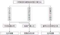
The invention provides a fracture-cavity type oil reservoir parameter calculation method, which comprises the following steps:
establishing a water injection indicating curve, a liquid level recovery curve and an energy indicating curve of the fracture;
according to the slope k of the water injection indication curve and the compression coefficient C of the crude oil0Calculating the remote well reserve;
calculating the far well energy by using a straight line extrapolation method according to the liquid level recovery curve;
and respectively selecting one production node of the water injection indicating curve and one production node of the energy indicating curve, and calculating the fracture starting pressure difference of a near well and the fracture starting pressure difference of a far well of the two nodes.
Preferably, the far well reserves are calculated by:
calculating a far well reserve parameter according to the following formula (1):
V0=1/k*C0=1000/k (1)
in the formula, C0The crude oil compressibility, k, is the water flooding indication curve slope.
Preferably, the method for calculating the far-well energy by using the straight line extrapolation method according to the liquid level recovery curve comprises the following steps:
setting the production time t before shutting in the wellpTowards infinity, the far well energy parameter is calculated according to the following equation (2):

in the formula, PwsFor far well energy, PiIs the formation pressure, tpProduction time before shut-in, Δ tsTo accumulate shut-in time, μ is the fluid viscosity, k is the permeability, and h is the reservoir thickness.
Preferably, the method for calculating the fracture initiation pressure difference of the near well according to the data of one water injection node and one production node comprises the following steps:
near-well crack initiation pressure difference delta P when water injection is setWater injection 1Near well fracture initiation pressure differential Δ P at productionProduction 1Near well reserve Q duringwater injection l0, near well reserve Q at productioninjw=0、PH water column=PH oil column;
Equation (3) and equation (4) are formulated using the yield equation:
Ql=J*(P1–△Pproduction 1–Pwf1)=0 (3)
Qinjw=J*(Pwf1’–△PWater injection 1–P1)=0 (4)
According to the formula(3) + formula (4) Elimination of formation hydrostatic pressure P1To obtain:
Pwf1’–Pwf1=2△Pwater injection 1,Pwf1=PH oil column+PWell head,Pwf1’=PH water column+PIntercept moment;
Near-well fracture initiation pressure difference delta P during water injectionWater injection 1=(PIntercept moment–PWell head)/2;
Near-well fracture initiation pressure differential Δ P during productionProduction 1=(PWell head–PIntercept moment’)/2。
Wherein, PWell headFor wellhead pressure before water injection, Pwf1For bottom hole flow pressure during water injection, Pwf1' bottom hole flow pressure in production, P1Is the static pressure of the formation, PH water columnIs the pressure of the water column during water injection, PH oil columnColumn pressure during production, PIntercept momentIndicating for water injection the distance, P, of a selected node in the curve from the Y coordinate systemIntercept moment' indicates the distance of the selected node in the curve from the Y coordinate system for the energy.
Preferably, the method for calculating the fracture initiation pressure difference of the far well according to the fracture initiation pressure difference of the near well, the data of the other water injection node and the data of the other production node comprises the following steps:
setting crack starting pressure difference delta P of far well during water injectionProduction 2Fracture initiation differential pressure Δ P for an open hole at productionWater injection 2(ii) a Remote well reserve Q during water injectionl' 0, remote well reserve in production Qinjw’=0、PH water column=PH oil column;
Obtaining a formula (5) and a formula (6) by using a yield formula;
Ql’=J*(P2–△Pproduction 1–△PProduction 2–Pwf)=0 (5)
Qinjw’=J*(Pwf’–△PProduction 1–△PProduction 2–P2)=0 (6)
Formula (5) + formula (6) eliminating the column pressure P2,Pwf1=PWell head,Pwf’=PInflection point;
Crack initiation pressure difference delta P of far well during water injectionWater injection 2=△PStart-up 1+△PStart 2=(PInflection point–PWell head)/2;
Fracture initiation pressure difference delta P of far well during productionProduction 2=(PWell head–PInflection point’)/2。
Wherein, PWell headFor wellhead pressure before water injection, PwfFor bottom hole flow pressure during water injection, Pwf' bottom hole flow pressure in production, P2Is the pressure of the water column, PInflection pointInjection pressure, P, for the reserve of the well into which the water is injected during water injectionInflection point' bottom hole pressure of water injection into remote well reserves at production time.
Compared with the prior art, the invention has the advantages that:
the method of the invention determines the remote well reserve, the remote well energy and the fracture starting differential pressure parameters according to the water injection indication curve, the liquid level recovery curve and the energy indication curve, determines the reservoir parameters, determines the production condition of each single well and the real reason of the low efficiency of the single well production, provides guidance for effectively using the second reservoir, namely accurately determining the high-pressure water injection and oil increase well selection conditions, and improves the fracture type oil reservoir recovery ratio to realize the production and cave-in, thereby being worthy of popularization.
Drawings
In order to more clearly illustrate the embodiments of the present invention or the technical solutions in the prior art, the drawings used in the description of the embodiments or the prior art will be briefly described below, it is obvious that the drawings in the following description are only some embodiments of the present invention, and for those skilled in the art, other drawings can be obtained according to the drawings without creative efforts.
FIG. 1 is a process for calculating reservoir parameters of a fracture-cavity reservoir according to the present invention;
FIG. 2 is a schematic diagram of a water injection indication curve of a fracture-cavity type oil reservoir provided by the invention;
FIG. 3 is a schematic diagram of an energy indicating curve for a fracture-cavity reservoir provided by the present invention;
FIG. 4 is a schematic diagram of a fracture-cavity reservoir level recovery curve provided by the present invention;
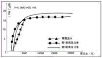
FIG. 5 provides a water injection indication curve for a single well S in accordance with an embodiment of the present invention;
FIG. 6 provides a graph indicating the energy of a single well S in accordance with an embodiment of the present invention;
FIG. 7 is a graph illustrating the fluid level recovery for a single well S according to an embodiment of the present invention;
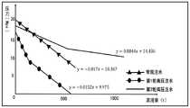
FIG. 8 is a graph of the relationship between remote well reserve and oil production after high pressure water injection in accordance with an embodiment of the present invention;
FIG. 9 is a graph of energy production versus oil production for a remote well after high pressure water injection in accordance with an embodiment.
Detailed Description
The technical solutions in the embodiments of the present invention will be clearly and completely described below with reference to fig. 1 to 9 in the embodiments of the present invention, and it is obvious that the described embodiments are only a part of the embodiments of the present invention, and not all embodiments. All other embodiments, which can be derived by a person skilled in the art from the embodiments given herein without making any creative effort, shall fall within the protection scope of the present invention.
The invention provides a fracture-cavity type oil reservoir parameter calculation method which comprises the following steps:
taking the high-pressure water injection well of the A block of the fractured-vuggy reservoir of the tower river oil field as an example, the development controlled factors of the reservoir of the fractured-vuggy reservoir of the tower river carbonate rock are complex, the heterogeneity is strong, the types of reservoir rocks are various, and various reservoir body types such as caves, holes and cracks exist in the whole reservoir unit.
The invention aims at a reservoir parameter calculation method, takes a single well S in the area as an example, and the specific calculation method is as follows:
s1: establishing a water injection indication curve as shown in FIG. 5 during the water injection process; establishing a liquid level recovery curve as shown in figure 6 in the well opening and closing stages; an energy indicating curve as shown in fig. 7 was established during the production process.
S2: as shown in fig. 5, the water injection indication curve of the well can be obtained, and the well has three stages: normal water injection phase, first high pressure injectionA water stage and a second high-pressure water injection stage; the water injection indicating curve has three sections of slopes, and a formula V is calculated according to the reserve of the far well0=1/k*C0The well reserve V of the well at the conventional water injection stage is 5.8 ten thousand tons, and the well reserve V of the first round of high-pressure water injection stage is 28.8 ten thousand tons; the remote well reserve V of the second high-pressure water injection stage is 63.4 ten thousand tons; illustrating that high pressure water injection makes the reservoir available.
S3: drawing the liquid level conversion pressure data in the liquid level data according to the liquid level recovery curve into a semilogarithmic coordinate system, and setting the shut-in time t as shown in FIG. 6pWhen the energy tends to infinity, the far well energy is 60.3MPa by utilizing a straight line extrapolation method.
S3: according to the characteristics of the water injection indicating curve and the energy indicating curve and the yield formula, as shown in figure 7, the fracture starting pressure difference delta P of the far well during water injectionWater injection 2=(PInflection point–PWell head) 2; fracture initiation pressure difference delta P of far well during productionProduction 2=(PWell head–PInflection point')/2; obtaining the remote well crack starting pressure difference delta P starting as 16.8MPa in water injection; the energy indicating curve calculates the production Δ P start-up to 17.1 MPa.
Based on the specific operation of the single well S, reservoir parameters of all the single wells of the area A of the tower-river fractured-vuggy reservoir are calculated, and the parameter calculation results are shown in Table 1.
TABLE 1 calculation results of parameters of each individual well in A block of Tahe oilfield


By calculating the reservoir parameters of the high-pressure water injection well in the area, the real reasons of the production conditions of each single well and the production inefficiency of the single well are determined, and the guidance is provided for effectively utilizing the second reservoir body, so that the fracture-cavity type oil reservoir recovery rate is improved, and the yield is increased.
From the geological aspect, the fracture-cavity type and double-cavity type reservoir structures have multiple sets of reservoir bodies and also have the potential of communicating remote well reserves through a high-pressure water injection development mode, so the fracture-cavity type and double-cavity type reservoir bodies are preferably selected for high-pressure water injection well selection.
From the aspect of engineering, by combining the comprehensive analysis of high-pressure water injection oil production, remote well reserve and remote well energy, as can be seen from fig. 8 and 9, under the conventional water injection, although a plurality of reservoirs exist, the remote well reserve is still less than 10 ten thousand tons, the remote well energy is weak and less than 40Mpa, and the reserve sealed by the remote well cannot be effectively used by normal-pressure water injection; after the high-pressure water injection measures are preferably implemented, when the energy of a far well is more than 40Mpa, the reserve of the far well is more than 10 ten thousand tons, and the oil production is large, the high-pressure water injection well selection conditions are further determined as follows: firstly, storing bodies in a fracture-cavity type and a double-cavity type, secondly, storing capacity of a far well is still less than 10 ten thousand tons, and thirdly, energy intensity of the far well is less than 40 Mpa; through an independent high-pressure water injection development mode, remote well energy is effectively supplemented, the water injection spread range is expanded, and the oil increasing effect is remarkable.
According to the analysis result of the high-pressure water injection oil replacement effect and the high-pressure water injection well selection conditions, the single-hole type reservoir body does not have the potential of high-pressure water injection communication remote well reserves; under the fracture-cavity reservoir body, when the injection pressure is more than 18MPa and the strength is more than 350m3After the accumulated injection amount exceeds 5700 tons, under the double-hole type reservoir body, when the injection pressure is more than 24Mpa and the strength is more than 370m3And d, after the accumulated injection amount exceeds 7200 tons, calculating and evaluating, finding that the communication cracks among the reservoirs are effectively opened, the spread range of injected water is expanded, the energy of a far well is continuously supplemented, remarkably evaluating the yield-increasing effect of replacing oil by high-pressure water injection, finding that the communication cracks among the reservoirs are effectively opened, the spread range of the injected water is expanded, the energy of the far well is continuously supplemented, and remarkably increasing the yield effect of replacing oil by high-pressure water injection.
In conclusion, the calculation method of the invention determines the remote well reserve, the remote well energy and the fracture starting differential pressure parameters according to the water injection indication curve, the liquid level recovery curve and the energy indication curve, determines the reservoir parameters, defines the production condition of each single well and the real reasons of the low efficiency of the single well production, provides guidance for effectively using the second reservoir, namely accurately determines the high-pressure water injection oil-increasing well selection conditions, improves the recovery ratio of the fracture-cavity type oil reservoir, realizes the production increase, and is worthy of popularization.
While preferred embodiments of the present invention have been described, additional variations and modifications in those embodiments may occur to those skilled in the art once they learn of the basic inventive concepts. Therefore, it is intended that the appended claims be interpreted as including preferred embodiments and all such alterations and modifications as fall within the scope of the invention.
It will be apparent to those skilled in the art that various changes and modifications may be made in the present invention without departing from the spirit and scope of the invention. Thus, if such modifications and variations of the present invention fall within the scope of the claims of the present invention and their equivalents, the present invention is also intended to include such modifications and variations.
Claims (3)
Translated fromChinese
Priority Applications (1)
| Application Number | Priority Date | Filing Date | Title |
|---|---|---|---|
| CN202110162655.9ACN112761582B (en) | 2021-02-05 | 2021-02-05 | Fracture-cavity type oil reservoir parameter calculation method |
Applications Claiming Priority (1)
| Application Number | Priority Date | Filing Date | Title |
|---|---|---|---|
| CN202110162655.9ACN112761582B (en) | 2021-02-05 | 2021-02-05 | Fracture-cavity type oil reservoir parameter calculation method |
Publications (2)
| Publication Number | Publication Date |
|---|---|
| CN112761582A CN112761582A (en) | 2021-05-07 |
| CN112761582Btrue CN112761582B (en) | 2022-02-25 |
Family
ID=75705164
Family Applications (1)
| Application Number | Title | Priority Date | Filing Date |
|---|---|---|---|
| CN202110162655.9AExpired - Fee RelatedCN112761582B (en) | 2021-02-05 | 2021-02-05 | Fracture-cavity type oil reservoir parameter calculation method |
Country Status (1)
| Country | Link |
|---|---|
| CN (1) | CN112761582B (en) |
Families Citing this family (2)
| Publication number | Priority date | Publication date | Assignee | Title |
|---|---|---|---|---|
| CN115392601A (en)* | 2021-05-24 | 2022-11-25 | 中国石油化工股份有限公司 | Analysis method, electronic equipment and medium for high pressure of supersaturated reservoir water flooding for oil replacement |
| CN119266785A (en)* | 2023-07-05 | 2025-01-07 | 中国石油天然气股份有限公司 | A method and device for calculating water drive controlled reserves for high pressure expansion water injection in oil reservoirs |
Citations (11)
| Publication number | Priority date | Publication date | Assignee | Title |
|---|---|---|---|---|
| RU2107155C1 (en)* | 1993-06-16 | 1998-03-20 | Игорь Тихонович Мищенко | Method for development of oil deposits |
| CN101942984A (en)* | 2010-01-27 | 2011-01-12 | 中国石油化工股份有限公司 | Fracture-cave type carbonate reservoir waterflooding oil replacement recovery method |
| CN105507858A (en)* | 2015-07-20 | 2016-04-20 | 塔里木油田分公司勘探开发研究院 | Immiscible gas injection and oil replacement type exploitation method for ultra-deep fractured-vuggy carbonate reservoirs |
| CN105626009A (en)* | 2015-12-17 | 2016-06-01 | 中国石油天然气股份有限公司 | Quantitative evaluation method for single-well water injection oil replacement effect of fracture-cave carbonate reservoir |
| CN106150477A (en)* | 2015-04-23 | 2016-11-23 | 中国石油化工股份有限公司 | A kind of method determining single well controlled reserves |
| CN106677750A (en)* | 2017-01-11 | 2017-05-17 | 西南石油大学 | Carbonate rock reservoir karst cave-fracture reservoir body water injection indication curve interpretation model |
| CN106777628A (en)* | 2016-06-29 | 2017-05-31 | 中国石油大学(华东) | Consider the oil reservoir injectivity and productivity plate method for drafting of non-Darcy flow |
| CN108386187A (en)* | 2018-03-15 | 2018-08-10 | 中国石油化工股份有限公司 | The method for analyzing reservoir structure based on oil well indicative curve |
| CN110334431A (en)* | 2019-07-02 | 2019-10-15 | 西南石油大学 | A method for single well controlled reserves calculation and residual gas analysis in low permeability tight gas reservoirs |
| CN110644975A (en)* | 2019-09-27 | 2020-01-03 | 西安石油大学 | A Quantitative Interpretation Method for Tracer Curves in Fracture-cavity Reservoirs |
| CN111581786A (en)* | 2020-04-19 | 2020-08-25 | 东北石油大学 | Well Test Interpretation Model for Analyzing Fracture-cavity Tandem Mode Dual Pore Composite Reservoir |
Family Cites Families (5)
| Publication number | Priority date | Publication date | Assignee | Title |
|---|---|---|---|---|
| AU5836701A (en)* | 2000-04-24 | 2001-11-07 | Shell Int Research | In situ recovery of hydrocarbons from a kerogen-containing formation |
| US6978672B1 (en)* | 2004-06-18 | 2005-12-27 | Schlumberger Technology Corporation | Wireline apparatus for measuring steaming potentials and determining earth formation characteristics |
| US7882893B2 (en)* | 2008-01-11 | 2011-02-08 | Legacy Energy | Combined miscible drive for heavy oil production |
| CN113090236A (en)* | 2017-01-11 | 2021-07-09 | 西南石油大学 | Carbonate reservoir double-karst-cave reservoir body water injection indication curve interpretation model |
| CN109697538A (en)* | 2017-10-22 | 2019-04-30 | 哈尔滨石油学院 | Carbonate Reservoir Caves-constant volume physical efficiency amount indicative curve interpretation model |
- 2021
- 2021-02-05CNCN202110162655.9Apatent/CN112761582B/ennot_activeExpired - Fee Related
Patent Citations (11)
| Publication number | Priority date | Publication date | Assignee | Title |
|---|---|---|---|---|
| RU2107155C1 (en)* | 1993-06-16 | 1998-03-20 | Игорь Тихонович Мищенко | Method for development of oil deposits |
| CN101942984A (en)* | 2010-01-27 | 2011-01-12 | 中国石油化工股份有限公司 | Fracture-cave type carbonate reservoir waterflooding oil replacement recovery method |
| CN106150477A (en)* | 2015-04-23 | 2016-11-23 | 中国石油化工股份有限公司 | A kind of method determining single well controlled reserves |
| CN105507858A (en)* | 2015-07-20 | 2016-04-20 | 塔里木油田分公司勘探开发研究院 | Immiscible gas injection and oil replacement type exploitation method for ultra-deep fractured-vuggy carbonate reservoirs |
| CN105626009A (en)* | 2015-12-17 | 2016-06-01 | 中国石油天然气股份有限公司 | Quantitative evaluation method for single-well water injection oil replacement effect of fracture-cave carbonate reservoir |
| CN106777628A (en)* | 2016-06-29 | 2017-05-31 | 中国石油大学(华东) | Consider the oil reservoir injectivity and productivity plate method for drafting of non-Darcy flow |
| CN106677750A (en)* | 2017-01-11 | 2017-05-17 | 西南石油大学 | Carbonate rock reservoir karst cave-fracture reservoir body water injection indication curve interpretation model |
| CN108386187A (en)* | 2018-03-15 | 2018-08-10 | 中国石油化工股份有限公司 | The method for analyzing reservoir structure based on oil well indicative curve |
| CN110334431A (en)* | 2019-07-02 | 2019-10-15 | 西南石油大学 | A method for single well controlled reserves calculation and residual gas analysis in low permeability tight gas reservoirs |
| CN110644975A (en)* | 2019-09-27 | 2020-01-03 | 西安石油大学 | A Quantitative Interpretation Method for Tracer Curves in Fracture-cavity Reservoirs |
| CN111581786A (en)* | 2020-04-19 | 2020-08-25 | 东北石油大学 | Well Test Interpretation Model for Analyzing Fracture-cavity Tandem Mode Dual Pore Composite Reservoir |
Also Published As
| Publication number | Publication date |
|---|---|
| CN112761582A (en) | 2021-05-07 |
Similar Documents
| Publication | Publication Date | Title |
|---|---|---|
| US11408264B2 (en) | Volumetric fracturing method of temporarily plugging and diverting through functional slick water with oil displacement agent injected simultaneously | |
| CN111236906B (en) | Method for improving fracture complexity through normal-pressure or deep shale gas main fracture deep plugging | |
| CN107066769B (en) | A high-efficiency acidizing design method suitable for ultra-deep fractured carbonate reservoirs | |
| CN111353205B (en) | Method for calculating formation pressure and dynamic productivity of water-producing gas well of tight gas reservoir | |
| CN108518218B (en) | A single well dynamic reserve determination method for multi-stage fracturing horizontal wells in unconventional oil and gas reservoirs | |
| CN112761582B (en) | Fracture-cavity type oil reservoir parameter calculation method | |
| MXPA02006977A (en) | Production optimization methodology for multilayer commingled reservoirs using commingled reservoir production performance data and production logging information. | |
| CN109783765B (en) | Energy analysis method for fracture-cavity type oil reservoir interference well testing | |
| CN108316915B (en) | Method for determining optimal dosage of fiber temporary plugging steering fluid in tight reservoir of oil and gas well | |
| CN113743037B (en) | Method for calculating water injection induced dynamic fracture change diversion capacity of low-permeability oil reservoir | |
| CN111626001B (en) | Method for improving refined water injection of oil extraction well | |
| RU2737043C1 (en) | Method for development of oil reservoir of multi-layer oil and gas condensate deposit | |
| CN105041274A (en) | Short-range two-layer oil-gas reservoir commingled production technique | |
| CN107339096A (en) | Rapid water exploration method for horizontal well | |
| CN112761602B (en) | Far well reserve potential excavating method for fracture-cavity oil reservoir | |
| CN110344800B (en) | Staged fracturing method for horizontal well | |
| CN105257288A (en) | Method for determining tight reservoir original reservoir pressure based on injection pressure decline well testing technology | |
| CN115841083B (en) | Method for determining injection volume of water injection wells | |
| CN118733924A (en) | Crack complexity diagnosis method and device | |
| RU2160362C2 (en) | Process of working of multipool oil field | |
| CN115961926A (en) | Compact reservoir pressure injection and flooding extraction integrated reservoir transformation method | |
| CN113530534B (en) | Reservoir reconstruction method and device | |
| RU2789784C1 (en) | Method for calculating the parameters of fractured-cavernous reservoirs | |
| CN115217456A (en) | Seepage volume fracturing method for improving shale gas horizontal well yield | |
| CN114526042B (en) | Segment design method and system for open hole well of long well section |
Legal Events
| Date | Code | Title | Description |
|---|---|---|---|
| PB01 | Publication | ||
| PB01 | Publication | ||
| SE01 | Entry into force of request for substantive examination | ||
| SE01 | Entry into force of request for substantive examination | ||
| CB03 | Change of inventor or designer information | Inventor after:Jiang Beibei Inventor after:Jiang Shasha Inventor after:Yang Qianlong Inventor after:Ma Xin Inventor after:Wang Na Inventor after:Xu Qiang Inventor after:Li Yingen Inventor after:Yuan Feiyu Inventor after:Li Haitao Inventor before:Ma Xin Inventor before:Jiang Beibei Inventor before:Jiang Shasha Inventor before:Yang Qianlong Inventor before:Yuan Feiyu Inventor before:Li Yingen Inventor before:Xu Qiang Inventor before:Wang Na | |
| CB03 | Change of inventor or designer information | ||
| GR01 | Patent grant | ||
| GR01 | Patent grant | ||
| CF01 | Termination of patent right due to non-payment of annual fee | Granted publication date:20220225 | |
| CF01 | Termination of patent right due to non-payment of annual fee |