CN112754616B - Ultrasonic positioning puncture system and storage medium - Google Patents
Ultrasonic positioning puncture system and storage mediumDownload PDFInfo
- Publication number
- CN112754616B CN112754616BCN202011610690.4ACN202011610690ACN112754616BCN 112754616 BCN112754616 BCN 112754616BCN 202011610690 ACN202011610690 ACN 202011610690ACN 112754616 BCN112754616 BCN 112754616B
- Authority
- CN
- China
- Prior art keywords
- coordinate system
- joint
- ultrasonic detection
- ultrasonic
- mechanical arm
- Prior art date
- Legal status (The legal status is an assumption and is not a legal conclusion. Google has not performed a legal analysis and makes no representation as to the accuracy of the status listed.)
- Active
Links
- 238000001514detection methodMethods0.000claimsabstractdescription152
- 238000006243chemical reactionMethods0.000claimsabstractdescription71
- 238000004590computer programMethods0.000claimsabstractdescription18
- 239000000523sampleSubstances0.000claimsdescription55
- 230000033001locomotionEffects0.000claimsdescription21
- 230000003068static effectEffects0.000claimsdescription10
- 238000002604ultrasonographyMethods0.000claimsdescription6
- 230000000712assemblyEffects0.000claims1
- 238000000429assemblyMethods0.000claims1
- 210000001503jointAnatomy0.000description27
- 230000009466transformationEffects0.000description27
- 238000000034methodMethods0.000description21
- 239000011159matrix materialSubstances0.000description16
- 238000004364calculation methodMethods0.000description10
- 238000010586diagramMethods0.000description8
- 238000006073displacement reactionMethods0.000description5
- 230000008569processEffects0.000description5
- 230000003902lesionEffects0.000description4
- 230000003287optical effectEffects0.000description4
- 238000002679ablationMethods0.000description3
- 238000003780insertionMethods0.000description3
- 230000037431insertionEffects0.000description3
- 238000011161developmentMethods0.000description2
- 238000005516engineering processMethods0.000description2
- 238000004519manufacturing processMethods0.000description2
- 238000013507mappingMethods0.000description2
- 238000009825accumulationMethods0.000description1
- 230000003321amplificationEffects0.000description1
- 238000001574biopsyMethods0.000description1
- 238000004422calculation algorithmMethods0.000description1
- 230000008859changeEffects0.000description1
- 230000001419dependent effectEffects0.000description1
- 238000013461designMethods0.000description1
- 238000002059diagnostic imagingMethods0.000description1
- 238000002592echocardiographyMethods0.000description1
- 230000004807localizationEffects0.000description1
- 230000007246mechanismEffects0.000description1
- 238000012986modificationMethods0.000description1
- 230000004048modificationEffects0.000description1
- 238000003199nucleic acid amplification methodMethods0.000description1
- 239000000126substanceSubstances0.000description1
- 238000000844transformationMethods0.000description1
- 238000011426transformation methodMethods0.000description1
Images


Classifications
- A—HUMAN NECESSITIES
- A61—MEDICAL OR VETERINARY SCIENCE; HYGIENE
- A61B—DIAGNOSIS; SURGERY; IDENTIFICATION
- A61B17/00—Surgical instruments, devices or methods
- A61B17/34—Trocars; Puncturing needles
- A61B17/3403—Needle locating or guiding means
- A—HUMAN NECESSITIES
- A61—MEDICAL OR VETERINARY SCIENCE; HYGIENE
- A61B—DIAGNOSIS; SURGERY; IDENTIFICATION
- A61B34/00—Computer-aided surgery; Manipulators or robots specially adapted for use in surgery
- A61B34/20—Surgical navigation systems; Devices for tracking or guiding surgical instruments, e.g. for frameless stereotaxis
- A—HUMAN NECESSITIES
- A61—MEDICAL OR VETERINARY SCIENCE; HYGIENE
- A61B—DIAGNOSIS; SURGERY; IDENTIFICATION
- A61B34/00—Computer-aided surgery; Manipulators or robots specially adapted for use in surgery
- A61B34/30—Surgical robots
- A—HUMAN NECESSITIES
- A61—MEDICAL OR VETERINARY SCIENCE; HYGIENE
- A61B—DIAGNOSIS; SURGERY; IDENTIFICATION
- A61B34/00—Computer-aided surgery; Manipulators or robots specially adapted for use in surgery
- A61B34/70—Manipulators specially adapted for use in surgery
- A—HUMAN NECESSITIES
- A61—MEDICAL OR VETERINARY SCIENCE; HYGIENE
- A61B—DIAGNOSIS; SURGERY; IDENTIFICATION
- A61B34/00—Computer-aided surgery; Manipulators or robots specially adapted for use in surgery
- A61B34/70—Manipulators specially adapted for use in surgery
- A61B34/77—Manipulators with motion or force scaling
- A—HUMAN NECESSITIES
- A61—MEDICAL OR VETERINARY SCIENCE; HYGIENE
- A61B—DIAGNOSIS; SURGERY; IDENTIFICATION
- A61B8/00—Diagnosis using ultrasonic, sonic or infrasonic waves
- A61B8/08—Clinical applications
- A61B8/0833—Clinical applications involving detecting or locating foreign bodies or organic structures
- A61B8/085—Clinical applications involving detecting or locating foreign bodies or organic structures for locating body or organic structures, e.g. tumours, calculi, blood vessels, nodules
- A—HUMAN NECESSITIES
- A61—MEDICAL OR VETERINARY SCIENCE; HYGIENE
- A61B—DIAGNOSIS; SURGERY; IDENTIFICATION
- A61B8/00—Diagnosis using ultrasonic, sonic or infrasonic waves
- A61B8/42—Details of probe positioning or probe attachment to the patient
- A61B8/4209—Details of probe positioning or probe attachment to the patient by using holders, e.g. positioning frames
- A61B8/4218—Details of probe positioning or probe attachment to the patient by using holders, e.g. positioning frames characterised by articulated arms
- A—HUMAN NECESSITIES
- A61—MEDICAL OR VETERINARY SCIENCE; HYGIENE
- A61B—DIAGNOSIS; SURGERY; IDENTIFICATION
- A61B8/00—Diagnosis using ultrasonic, sonic or infrasonic waves
- A61B8/42—Details of probe positioning or probe attachment to the patient
- A61B8/4245—Details of probe positioning or probe attachment to the patient involving determining the position of the probe, e.g. with respect to an external reference frame or to the patient
- A—HUMAN NECESSITIES
- A61—MEDICAL OR VETERINARY SCIENCE; HYGIENE
- A61B—DIAGNOSIS; SURGERY; IDENTIFICATION
- A61B90/00—Instruments, implements or accessories specially adapted for surgery or diagnosis and not covered by any of the groups A61B1/00 - A61B50/00, e.g. for luxation treatment or for protecting wound edges
- A61B90/36—Image-producing devices or illumination devices not otherwise provided for
- A61B90/37—Surgical systems with images on a monitor during operation
- A—HUMAN NECESSITIES
- A61—MEDICAL OR VETERINARY SCIENCE; HYGIENE
- A61B—DIAGNOSIS; SURGERY; IDENTIFICATION
- A61B17/00—Surgical instruments, devices or methods
- A61B17/34—Trocars; Puncturing needles
- A61B17/3403—Needle locating or guiding means
- A61B2017/3405—Needle locating or guiding means using mechanical guide means
- A—HUMAN NECESSITIES
- A61—MEDICAL OR VETERINARY SCIENCE; HYGIENE
- A61B—DIAGNOSIS; SURGERY; IDENTIFICATION
- A61B17/00—Surgical instruments, devices or methods
- A61B17/34—Trocars; Puncturing needles
- A61B17/3403—Needle locating or guiding means
- A61B2017/3413—Needle locating or guiding means guided by ultrasound
- A—HUMAN NECESSITIES
- A61—MEDICAL OR VETERINARY SCIENCE; HYGIENE
- A61B—DIAGNOSIS; SURGERY; IDENTIFICATION
- A61B34/00—Computer-aided surgery; Manipulators or robots specially adapted for use in surgery
- A61B34/20—Surgical navigation systems; Devices for tracking or guiding surgical instruments, e.g. for frameless stereotaxis
- A61B2034/2046—Tracking techniques
- A61B2034/2063—Acoustic tracking systems, e.g. using ultrasound
- A—HUMAN NECESSITIES
- A61—MEDICAL OR VETERINARY SCIENCE; HYGIENE
- A61B—DIAGNOSIS; SURGERY; IDENTIFICATION
- A61B34/00—Computer-aided surgery; Manipulators or robots specially adapted for use in surgery
- A61B34/20—Surgical navigation systems; Devices for tracking or guiding surgical instruments, e.g. for frameless stereotaxis
- A61B2034/2046—Tracking techniques
- A61B2034/2065—Tracking using image or pattern recognition
- A—HUMAN NECESSITIES
- A61—MEDICAL OR VETERINARY SCIENCE; HYGIENE
- A61B—DIAGNOSIS; SURGERY; IDENTIFICATION
- A61B90/00—Instruments, implements or accessories specially adapted for surgery or diagnosis and not covered by any of the groups A61B1/00 - A61B50/00, e.g. for luxation treatment or for protecting wound edges
- A61B90/36—Image-producing devices or illumination devices not otherwise provided for
- A61B2090/364—Correlation of different images or relation of image positions in respect to the body
- A—HUMAN NECESSITIES
- A61—MEDICAL OR VETERINARY SCIENCE; HYGIENE
- A61B—DIAGNOSIS; SURGERY; IDENTIFICATION
- A61B90/00—Instruments, implements or accessories specially adapted for surgery or diagnosis and not covered by any of the groups A61B1/00 - A61B50/00, e.g. for luxation treatment or for protecting wound edges
- A61B90/36—Image-producing devices or illumination devices not otherwise provided for
- A61B90/37—Surgical systems with images on a monitor during operation
- A61B2090/378—Surgical systems with images on a monitor during operation using ultrasound
Landscapes
- Health & Medical Sciences (AREA)
- Life Sciences & Earth Sciences (AREA)
- Surgery (AREA)
- Engineering & Computer Science (AREA)
- Nuclear Medicine, Radiotherapy & Molecular Imaging (AREA)
- Public Health (AREA)
- General Health & Medical Sciences (AREA)
- Veterinary Medicine (AREA)
- Biomedical Technology (AREA)
- Heart & Thoracic Surgery (AREA)
- Medical Informatics (AREA)
- Molecular Biology (AREA)
- Animal Behavior & Ethology (AREA)
- Pathology (AREA)
- Radiology & Medical Imaging (AREA)
- Robotics (AREA)
- Biophysics (AREA)
- Physics & Mathematics (AREA)
- Gynecology & Obstetrics (AREA)
- Oral & Maxillofacial Surgery (AREA)
- Vascular Medicine (AREA)
- Manipulator (AREA)
Abstract
Translated fromChinese
Description
Translated fromChinese技术领域technical field
本申请涉及机械臂控制领域,特别是涉及超声定位穿刺系统和存储介质。The present application relates to the field of robotic arm control, and in particular, to an ultrasonic positioning puncture system and a storage medium.
背景技术Background technique
传统的穿刺手术是医生在超声、CT、MRI等图像扫描设备的引导下,由医生手动将小型手术器械(如活检穿刺针等)送入患者体内,对病变部位进行检测或治疗,医生通过病灶附近的二维或三维扫描图像判断合适的入针点和入针方向,然后凭借经验手动完成穿刺操作。In the traditional puncture operation, under the guidance of image scanning equipment such as ultrasound, CT, and MRI, the doctor manually sends small surgical instruments (such as biopsy needles) into the patient's body to detect or treat the lesion. The nearby 2D or 3D scan images determine the appropriate needle entry point and needle entry direction, and then manually complete the puncture operation based on experience.
计算机辅助导航技术和机器人技术被引入到穿刺手术中。具有手术导航系统的穿刺机器人工作原理如下:首先由计算机将扫描的二维图像进行三维合成形成病灶附近的三维图像,然后由医生通过三维图像判断靶点位置和合适的入针路径并输入导航系统,再由导航系统计算出机器人操作臂的当前状态和目标点并规划出一条轨迹,最后操作臂按照规划的轨迹完成穿刺定位,再通过进针机构或医生手动完成进针,避免了纯手动操作带来的误差。然而,现有的导航技术通常通过光学定位对穿刺针和医学影像设备进行定位和配准,在医学影像的辅助下进行穿刺,但光学定位和配准的过程中存在较大的误差,并且在操作的过程中不能使光学小球被遮挡,限制了手术的实施。Computer-aided navigation techniques and robotics were introduced into puncture procedures. The working principle of the puncture robot with the surgical navigation system is as follows: first, the computer 3D synthesizes the scanned 2D image to form a 3D image near the lesion, and then the doctor judges the target position and the appropriate needle insertion path through the 3D image and inputs it into the navigation system. , and then the navigation system calculates the current state and target point of the robot manipulator arm and plans a trajectory. Finally, the manipulator arm completes the puncture positioning according to the planned trajectory, and then manually completes the needle insertion through the needle insertion mechanism or the doctor, avoiding pure manual operation. errors caused. However, the existing navigation technology usually locates and registers the puncture needle and medical imaging equipment through optical positioning, and performs puncture with the aid of medical images, but there are large errors in the process of optical positioning and registration, and in During the operation, the optical ball cannot be blocked, which limits the implementation of the operation.
发明内容SUMMARY OF THE INVENTION
本申请实施例提供了一种超声定位穿刺系统和存储介质,直接在超声影像中获取病灶坐标,而不需要通过光学定位等配准基准间接配准,以解决现有的医学影像导航下穿刺手术的定位和配准技术也存在误差的问题。The embodiments of the present application provide an ultrasonic positioning puncture system and a storage medium, which can directly obtain the coordinates of the lesion in the ultrasonic image without indirect registration through registration datums such as optical positioning, so as to solve the problem of the existing medical image navigation puncture operation There are also errors in the localization and registration techniques of .
第一方面,本申请实施例提供了一种超声定位穿刺系统,所述超声定位穿刺系统包括计算机设备、第一串联机械臂和搭载在所述第一串联机械臂末端的超声探测装置,所述计算机设备分别与所述第一串联机械臂和所述超声探测装置电性连接,所述计算机设备包括存储器和处理器,所述存储器中存储有计算机程序,所述处理器在运行所述计算机程序时执行下列步骤:在所述超声探测装置投射的超声探测平面内定位靶点的第一位置信息;获取所述超声探测平面的第一姿态信息以及所述第一串联机械臂的第二姿态信息;根据所述第一姿态信息和所述第二姿态信息,确定所述超声定位穿刺系统的参考坐标系与所述超声探测平面所在坐标系的位置转换关系;根据所述位置转换关系和所述第一位置信息,确定所述靶点在所述参考坐标系内的第二位置信息。In a first aspect, an embodiment of the present application provides an ultrasonic positioning and puncturing system. The ultrasonic positioning and puncturing system includes a computer device, a first serial manipulator arm, and an ultrasonic detection device mounted on the end of the first serial manipulator arm. Computer equipment is electrically connected to the first serial robotic arm and the ultrasonic detection device respectively, the computer equipment includes a memory and a processor, the memory stores a computer program, and the processor runs the computer program Perform the following steps: locate the first position information of the target point in the ultrasonic detection plane projected by the ultrasonic detection device; obtain the first attitude information of the ultrasonic detection plane and the second attitude information of the first serial robot arm ; According to the first attitude information and the second attitude information, determine the position conversion relationship between the reference coordinate system of the ultrasonic positioning puncture system and the coordinate system where the ultrasonic detection plane is located; According to the position conversion relationship and the described position conversion relationship The first position information determines the second position information of the target point in the reference coordinate system.
在其中的一些实施例中,在所述超声探测装置投射的超声探测平面内定位靶点的第一位置信息包括:获取由所述超声探测装置采集的超声图像,在所述超声图像中定位所述靶点的位置信息;根据所述靶点在所述超声图像中的位置信息以及所述超声探测装置的标定参数,确定所述靶点在所述超声探测装置投射的超声探测平面内的所述第一位置信息。In some of these embodiments, locating the first position information of the target point in the ultrasonic detection plane projected by the ultrasonic detection device includes: acquiring an ultrasonic image acquired by the ultrasonic detection device, and locating the target point in the ultrasonic image. The position information of the target point; according to the position information of the target point in the ultrasonic image and the calibration parameters of the ultrasonic detection device, determine the location of the target point in the ultrasonic detection plane projected by the ultrasonic detection device. describe the first location information.
在其中的一些实施例中,所述超声探测装置与所述第一串联机械臂的末端可转动地连接,所述超声探测平面形成于所述超声探测装置的末端端点并自所述超声探测装置的末端端点沿扇面延伸;所述超声探测平面跟随所述超声探测装置旋转,所述超声探测平面的旋转轴经过所述末端端点;所述第一姿态信息包括所述超声探测平面的旋转角度。In some of these embodiments, the ultrasonic detection device is rotatably connected to the end of the first serial manipulator, and the ultrasonic detection plane is formed at the end of the ultrasonic detection device and extends from the ultrasonic detection device. The end point of the ultrasonic detection plane extends along the fan plane; the ultrasonic detection plane rotates with the ultrasonic detection device, and the rotation axis of the ultrasonic detection plane passes through the end point; the first attitude information includes the rotation angle of the ultrasonic detection plane.
在其中的一些实施例中,所述第一位置信息包括所述靶点相对于所述末端端点的距离,以及所述靶点和所述末端端点的连接线与所述旋转轴的夹角。In some of the embodiments, the first position information includes the distance of the target point relative to the end point, and the included angle of the connecting line between the target point and the end point and the rotation axis.
在其中的一些实施例中,所述第一串联机械臂包括多个关节,多个所述关节包括:旋转关节和/或移动关节,所述第二姿态信息包括每个所述关节的运动量信息。In some of these embodiments, the first serial robotic arm includes a plurality of joints, the plurality of joints include: rotation joints and/or movement joints, and the second posture information includes motion amount information of each of the joints .
在其中的一些实施例中,根据所述第一姿态信息和所述第二姿态信息,确定所述超声定位穿刺系统的参考坐标系与所述超声探测平面所在坐标系的位置转换关系包括:在所述第一串联机械臂处于初始状态时,建立所述第一串联机械臂的参考坐标系和所述第一串联机械臂的各关节的关节坐标系,以及在所述超声探测装置处于初始状态时,以所述超声探测装置的末端端点为坐标原点建立探头坐标系;获取所述第一串联机械臂的参考坐标系和所述第一串联机械臂的各关节的关节坐标系的DH参数,并根据所述DH参数,确定所述第一串联机械臂的参考坐标系到所述第一串联机械臂的末端关节的关节坐标系之间的第一位置转换关系;获取所述探头坐标系的坐标原点在所述末端关节的关节坐标系内的位置信息,以及所述探头坐标系相对于所述末端关节的关节坐标系的姿态角,并根据该位置信息、姿态角以及所述第一位置转换关系,确定所述参考坐标系与所述探头坐标系之间的第二位置转换关系;获取所述超声探测平面的旋转角度,并根据所述旋转角度确定所述超声探测平面所在坐标系与所述探头坐标系之间的第三位置转换关系;根据所述第二位置转换关系和所述第三位置转换关系,确定所述超声定位穿刺系统的参考坐标系与所述超声探测平面所在坐标系的位置转换关系。In some of the embodiments, determining the position conversion relationship between the reference coordinate system of the ultrasonic positioning and puncturing system and the coordinate system where the ultrasonic detection plane is located according to the first attitude information and the second attitude information includes: When the first serial manipulator is in the initial state, the reference coordinate system of the first serial manipulator and the joint coordinate system of each joint of the first serial manipulator are established, and when the ultrasonic detection device is in the initial state When , take the end point of the ultrasonic detection device as the coordinate origin to establish a probe coordinate system; obtain the reference coordinate system of the first serial manipulator and the DH parameters of the joint coordinate system of each joint of the first serial manipulator, And according to the DH parameter, determine the first position conversion relationship between the reference coordinate system of the first serial manipulator and the joint coordinate system of the end joint of the first serial manipulator; obtain the coordinate system of the probe. The position information of the coordinate origin in the joint coordinate system of the terminal joint, and the attitude angle of the probe coordinate system relative to the joint coordinate system of the terminal joint, and according to the position information, attitude angle and the first position conversion relationship, determine the second position conversion relationship between the reference coordinate system and the probe coordinate system; obtain the rotation angle of the ultrasonic detection plane, and determine the coordinate system where the ultrasonic detection plane is located according to the rotation angle and the ultrasonic detection plane. The third position conversion relationship between the probe coordinate systems; according to the second position conversion relationship and the third position conversion relationship, determine the reference coordinate system of the ultrasonic positioning puncture system and the coordinates where the ultrasonic detection plane is located The position conversion relationship of the system.
在其中的一些实施例中,所述第一串联机械臂包括旋转关节和移动关节,旋转关节的关节坐标系的Z轴沿旋转轴设置,移动关节的关节坐标系的Z轴沿移动方向设置,参考坐标系与各关节的关节坐标系同为左手系或右手系,且当旋转关节与在前的移动关节连接时,旋转关节的关节坐标系的原点与该在前的移动关节的关节坐标系的原点重合。In some of the embodiments, the first serial manipulator includes a rotating joint and a moving joint, the Z axis of the joint coordinate system of the rotating joint is set along the rotating axis, and the Z axis of the joint coordinate system of the moving joint is set along the moving direction, The reference coordinate system and the joint coordinate system of each joint are both left-handed or right-handed systems, and when the rotary joint is connected to the previous mobile joint, the origin of the joint coordinate system of the rotary joint is the joint coordinate system of the previous mobile joint. The origin coincides.
在其中的一些实施例中,所述探头坐标系的X、Y、Z轴的方向与所述末端关节的关节坐标系的X、Y、Z轴的方向相同,且所述探头坐标系的Z轴和所述末端关节的关节坐标系的Z轴共线。In some of these embodiments, the directions of the X, Y, and Z axes of the probe coordinate system are the same as the directions of the X, Y, and Z axes of the joint coordinate system of the distal joint, and the Z axis of the probe coordinate system The axis is collinear with the Z-axis of the joint coordinate system of the end joint.
在其中的一些实施例中,所述第一串联机械臂的末端关节为并联运动平台,所述并联运动平台包括静平台、动平台和多个设置在所述静平台与所述动平台之间的伸缩组件,所述超声探测装置设于所述动平台。In some of the embodiments, the end joint of the first serial manipulator is a parallel motion platform, and the parallel motion platform includes a static platform, a moving platform, and a plurality of pieces disposed between the static platform and the moving platform The telescopic assembly, the ultrasonic detection device is set on the moving platform.
在其中的一些实施例中,所述超声定位穿刺系统还包括第二串联机械臂和搭载在所述第二串联机械臂末端的穿刺器械;所述计算机设备还分别与所述第二串联机械臂电性连接,所述处理器在运行所述计算机程序时还执行下列步骤:将所述靶点在所述参考坐标系内的第二位置信息作为目标穿刺点,控制所述第二串联机械臂的穿刺器械对所述目标穿刺点进行穿刺。In some of the embodiments, the ultrasonic positioning and puncturing system further includes a second serial robotic arm and a puncturing instrument mounted on the end of the second serial robotic arm; the computer equipment is further connected to the second serial robotic arm, respectively. electrically connected, the processor further executes the following steps when running the computer program: taking the second position information of the target point in the reference coordinate system as the target puncture point, and controlling the second serial robotic arm The puncture instrument punctures the target puncture point.
第二方面,本申请实施例提供了一种存储介质,所述存储介质中存储有计算机程序,所述计算机程序被设置为运行时执行下列步骤:In a second aspect, an embodiment of the present application provides a storage medium, where a computer program is stored in the storage medium, and the computer program is configured to execute the following steps when running:
在所述超声探测装置投射的超声探测平面内定位靶点的第一位置信息;Locating the first position information of the target point in the ultrasonic detection plane projected by the ultrasonic detection device;
获取所述超声探测平面的第一姿态信息以及所述第一串联机械臂的第二姿态信息;acquiring the first attitude information of the ultrasonic detection plane and the second attitude information of the first serial manipulator;
根据所述第一姿态信息和所述第二姿态信息,确定所述超声定位穿刺系统的参考坐标系与所述超声探测平面所在坐标系的位置转换关系;According to the first attitude information and the second attitude information, determine the position conversion relationship between the reference coordinate system of the ultrasonic positioning puncture system and the coordinate system where the ultrasonic detection plane is located;
根据所述位置转换关系和所述第一位置信息,确定所述靶点在所述参考坐标系内的第二位置信息。According to the position conversion relationship and the first position information, second position information of the target point in the reference coordinate system is determined.
相比于相关技术,本申请实施例提供的超声定位穿刺系统和存储介质,解决了,现有的医学影像导航下穿刺手术的定位和配准技术也存在误差的问题,提高了穿刺手术的精度。Compared with the related art, the ultrasonic positioning puncture system and storage medium provided by the embodiments of the present application solve the problem of errors in the existing positioning and registration technology of puncture operation under medical image navigation, and improve the accuracy of puncture operation. .
本申请的一个或多个实施例的细节在以下附图和描述中提出,以使本申请的其他特征、目的和优点更加简明易懂。The details of one or more embodiments of the application are set forth in the accompanying drawings and the description below in order to make other features, objects and advantages of the application more apparent.
附图说明Description of drawings
此处所说明的附图用来提供对本申请的进一步理解,构成本申请的一部分,本申请的示意性实施例及其说明用于解释本申请,并不构成对本申请的不当限定。在附图中:The drawings described herein are used to provide further understanding of the present application and constitute a part of the present application. The schematic embodiments and descriptions of the present application are used to explain the present application and do not constitute an improper limitation of the present application. In the attached image:
图1是本申请实施例提供的超声定位穿刺系统的结构框图。FIG. 1 is a structural block diagram of an ultrasonic positioning and puncturing system provided by an embodiment of the present application.
图2是本申请实施例提供的超声定位穿刺系统的工作方法的流程图。FIG. 2 is a flowchart of a working method of the ultrasonic positioning puncture system provided by the embodiment of the present application.
图3是本申请实施例的多关节机械臂的坐标转换方法的流程图。FIG. 3 is a flowchart of a coordinate conversion method for a multi-joint robotic arm according to an embodiment of the present application.
图4是本申请优选实施例提供的多关节机械臂的结构示意图。FIG. 4 is a schematic structural diagram of a multi-joint robotic arm provided by a preferred embodiment of the present application.
图5是本申请优选实施例提供的多关节机械臂的机械坐标系和关节坐标系的示意图。FIG. 5 is a schematic diagram of a mechanical coordinate system and a joint coordinate system of a multi-joint manipulator provided by a preferred embodiment of the present application.
图6是本申请优选实施例的超声探测装置的探头坐标系与Stewart计算坐标系的示意图。FIG. 6 is a schematic diagram of a probe coordinate system and a Stewart calculation coordinate system of an ultrasonic detection device according to a preferred embodiment of the present application.
具体实施方式Detailed ways
为了使本申请的目的、技术方案及优点更加清楚明白,以下结合附图及实施例,对本申请进行描述和说明。应当理解,此处所描述的具体实施例仅仅用以解释本申请,并不用于限定本申请。基于本申请提供的实施例,本领域普通技术人员在没有作出创造性劳动的前提下所获得的所有其他实施例,都属于本申请保护的范围。此外,还可以理解的是,虽然这种开发过程中所作出的努力可能是复杂并且冗长的,然而对于与本申请公开的内容相关的本领域的普通技术人员而言,在本申请揭露的技术内容的基础上进行的一些设计,制造或者生产等变更只是常规的技术手段,不应当理解为本申请公开的内容不充分。In order to make the objectives, technical solutions and advantages of the present application clearer, the present application will be described and illustrated below with reference to the accompanying drawings and embodiments. It should be understood that the specific embodiments described herein are only used to explain the present application, but not to limit the present application. Based on the embodiments provided in the present application, all other embodiments obtained by those of ordinary skill in the art without creative work fall within the protection scope of the present application. In addition, it will also be appreciated that while such development efforts may be complex and lengthy, for those of ordinary skill in the art to which the present disclosure pertains, the techniques disclosed in this application Some changes in design, manufacture or production based on the content are only conventional technical means, and it should not be understood that the content disclosed in this application is not sufficient.
在本申请中提及“实施例”意味着,结合实施例描述的特定特征、结构或特性可以包含在本申请的至少一个实施例中。在说明书中的各个位置出现该短语并不一定均是指相同的实施例,也不是与其它实施例互斥的独立的或备选的实施例。本领域普通技术人员显式地和隐式地理解的是,本申请所描述的实施例在不冲突的情况下,可以与其它实施例相结合。Reference in this application to an "embodiment" means that a particular feature, structure, or characteristic described in connection with the embodiment can be included in at least one embodiment of the application. The appearances of the phrase in various places in the specification are not necessarily all referring to the same embodiment, nor a separate or alternative embodiment that is mutually exclusive of other embodiments. It is explicitly and implicitly understood by those of ordinary skill in the art that the embodiments described in this application may be combined with other embodiments without conflict.
除非另作定义,本申请所涉及的技术术语或者科学术语应当为本申请所属技术领域内具有一般技能的人士所理解的通常意义。本申请所涉及的“一”、“一个”、“一种”、“该”等类似词语并不表示数量限制,可表示单数或复数。本申请所涉及的术语“包括”、“包含”、“具有”以及它们任何变形,意图在于覆盖不排他的包含;例如包含了一系列步骤或模块(单元)的过程、方法、系统、产品或设备没有限定于已列出的步骤或单元,而是可以还包括没有列出的步骤或单元,或可以还包括对于这些过程、方法、产品或设备固有的其它步骤或单元。本申请所涉及的“连接”、“相连”、“耦接”等类似的词语并非限定于物理的或者机械的连接,而是可以包括电气的连接,不管是直接的还是间接的。本申请所涉及的“多个”是指大于或者等于两个。“和/或”描述关联对象的关联关系,表示可以存在三种关系,例如,“A和/或B”可以表示:单独存在A,同时存在A和B,单独存在B这三种情况。本申请所涉及的术语“第一”、“第二”、“第三”等仅仅是区别类似的对象,不代表针对对象的特定排序。Unless otherwise defined, the technical or scientific terms involved in this application shall have the usual meanings understood by those with ordinary skill in the technical field to which this application belongs. Words such as "a", "an", "an", "the" and the like mentioned in this application do not denote a quantitative limitation, and may denote the singular or the plural. The terms "comprising", "comprising", "having" and any of their variants referred to in this application are intended to cover non-exclusive inclusion; for example, a process, method, system, product or process comprising a series of steps or modules (units) The apparatus is not limited to the steps or units listed, but may further include steps or units not listed, or may further include other steps or units inherent to the process, method, product or apparatus. Words like "connected," "connected," "coupled," and the like referred to in this application are not limited to physical or mechanical connections, but may include electrical connections, whether direct or indirect. The "plurality" referred to in this application means greater than or equal to two. "And/or" describes the association relationship between associated objects, indicating that there can be three kinds of relationships. For example, "A and/or B" can mean that A exists alone, A and B exist at the same time, and B exists alone. The terms "first", "second", "third", etc. involved in this application are only to distinguish similar objects, and do not represent a specific order for the objects.
本实施例提供了一种超声定位穿刺系统,图1是本申请实施例提供的超声定位穿刺系统的结构框图,如图1所示,该超声定位穿刺系统包括计算机设备101、第一串联机械臂102和搭载在第一串联机械臂102末端的超声探测装置103,计算机设备101分别与第一串联机械臂102和超声探测装置103电性连接,计算机设备101包括存储器1011和处理器1012,存储器1011中存储有计算机程序10111。This embodiment provides an ultrasonic positioning and puncturing system. FIG. 1 is a structural block diagram of the ultrasonic positioning and puncturing system provided by the embodiment of the present application. As shown in FIG. 1 , the ultrasonic positioning and puncturing system includes a
图2是本申请实施例提供的超声定位穿刺系统的工作方法的流程图,如图2所示,处理器1012在运行计算机程序时执行下列步骤S201至步骤S204。FIG. 2 is a flowchart of the working method of the ultrasonic positioning and puncturing system provided by the embodiment of the present application. As shown in FIG. 2 , the
步骤S201,在超声探测装置投射的超声探测平面内定位靶点的第一位置信息。Step S201 , locate the first position information of the target point in the ultrasonic detection plane projected by the ultrasonic detection device.
超声探测装置103投射的超声探测平面通常呈扇面状,扇面的扇心即为超声发生的起点位置,在扇心位置发出超声并接收物质反射的回波来探测该超声探测平面内的目标位置。The ultrasonic detection plane projected by the
由于超声探测平面只能够探测到一个扇面的信息,而待穿刺的靶点位置位于人体内的一个空间位置内,因此若要探测到准确的靶点位置,搭载超声探测装置103的第一串联机械臂102需要将超声探测装置103移动到靶点附近位置,在移动到靶点附近位置时,第一串联机械臂102的各关节的运动量会发生变化,在本申请实施例中这些关节运动量的集合称为第二姿态信息。在其中的一些实施例中,第一串联机械臂包括多个关节,多个关节包括:旋转关节和/或移动关节,第二姿态信息包括每个关节的运动量信息。Since the ultrasonic detection plane can only detect the information of one sector, and the position of the target to be punctured is located in a spatial position in the human body, to detect the accurate target position, the first serial machine equipped with the
在其中的一些实施例中,超声探测装置与第一串联机械臂102的末端可转动地连接,超声探测平面形成于超声探测装置的末端端点并自超声探测装置的末端端点沿扇面延伸;超声探测平面跟随超声探测装置旋转,超声探测平面的旋转轴经过末端端点;第一姿态信息包括超声探测平面的旋转角度。In some of these embodiments, the ultrasonic detection device is rotatably connected to the end of the first serial
当超声探测装置103被移动到靶点附近位置之后,超声探测平面朝向靶点方向照射,为了在超声探测平面中显示岀靶点,在本申请实施例中沿扇面的对称轴旋转超声探测装置103,超声探测平面随之旋转,从而实现圆台形或圆锥形空间区域内的靶点探测,每个超声探测平面的超声图像都会实时显示在电子屏幕上。一旦在电子屏幕上观察到与靶点特征相符的图像,则可以该靶点在超声图像内的位置确定靶点在真实的超声探测平面内的位置,即为第一位置信息。After the
例如,确定靶点在超声探测平面内的位置,通过实时获取由超声探测装置采集的超声图像,在超声图像中定位靶点的位置信息;然后根据靶点在超声图像中的位置信息以及超声探测装置的标定参数,确定靶点在超声探测装置投射的超声探测平面内的第一位置信息。超声探测装置的标定参数包括但不限于以下至少之一:阵元数、曲率半径、线阵宽度、查扫视野(FOV)等。For example, determine the position of the target point in the ultrasonic detection plane, and locate the position information of the target point in the ultrasonic image by acquiring the ultrasonic image collected by the ultrasonic detection device in real time; then according to the position information of the target point in the ultrasonic image and the ultrasonic detection The calibration parameters of the device determine the first position information of the target point in the ultrasonic detection plane projected by the ultrasonic detection device. The calibration parameters of the ultrasonic detection device include, but are not limited to, at least one of the following: the number of array elements, the radius of curvature, the width of the linear array, the field of view (FOV), and the like.
第一位置信息可以采用直角坐标或极坐标的方式表示。例如,在采用极坐标方式表示的情况下,第一位置信息包括靶点相对于末端端点的距离,以及靶点和末端端点的连接线与旋转轴的夹角。The first position information may be represented in the form of Cartesian coordinates or polar coordinates. For example, in the case of using polar coordinates to represent, the first position information includes the distance of the target point relative to the end point, and the angle between the connecting line between the target point and the end point and the rotation axis.
步骤S202,获取超声探测平面的第一姿态信息以及第一串联机械臂的第二姿态信息。Step S202, acquiring first attitude information of the ultrasonic detection plane and second attitude information of the first serial manipulator.
步骤S203,根据第一姿态信息和第二姿态信息,确定超声定位穿刺系统的参考坐标系与超声探测平面所在坐标系的位置转换关系。Step S203, according to the first attitude information and the second attitude information, determine the position conversion relationship between the reference coordinate system of the ultrasonic positioning puncture system and the coordinate system where the ultrasonic detection plane is located.
步骤S204,根据位置转换关系和第一位置信息,确定靶点在参考坐标系内的第二位置信息。Step S204, according to the position conversion relationship and the first position information, determine the second position information of the target point in the reference coordinate system.
在超声探测平面的第一姿态信息和第一串联机械臂的第二姿态信息确定的情况下,则超声探测平面上的任意一点与参考坐标系的转换关系就是确定的,因此,根据第一姿态信息和第二姿态信息,可以确定超声定位穿刺系统的参考坐标系与超声探测平面所在坐标系的位置转换关系,再根据该位置转换关系和第一位置信息就能够确定靶点在参考坐标系内的第二位置信息,实现靶点在参考坐标系下的定位。When the first attitude information of the ultrasonic detection plane and the second attitude information of the first serial manipulator are determined, the conversion relationship between any point on the ultrasonic detection plane and the reference coordinate system is determined. Therefore, according to the first attitude information and the second attitude information, can determine the position conversion relationship between the reference coordinate system of the ultrasonic positioning puncture system and the coordinate system where the ultrasonic detection plane is located, and then according to the position conversion relationship and the first position information, it can be determined that the target point is in the reference coordinate system. The second position information of , realizes the positioning of the target point in the reference coordinate system.
需要说明的是,在上述流程中或者附图的流程图中示出的步骤可以在诸如一组计算机可执行指令的计算机系统中执行,并且,虽然在流程图中示出了逻辑顺序,但是在某些情况下,可以以不同于此处的顺序执行所示出或描述的步骤。例如,步骤S201也可以在步骤S202或步骤S203之后执行。It should be noted that the steps shown in the above flow or the flow chart of the accompanying drawings can be executed in a computer system such as a set of computer-executable instructions, and although a logical sequence is shown in the flow chart, in the In some cases, steps shown or described may be performed in an order different from that herein. For example, step S201 may also be performed after step S202 or step S203.
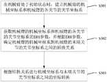
在其中的一些实施例中,根据第一姿态信息和第二姿态信息,确定超声定位穿刺系统的参考坐标系与超声探测平面所在坐标系的位置转换关系包括如下步骤:In some of these embodiments, according to the first attitude information and the second attitude information, determining the position conversion relationship between the reference coordinate system of the ultrasonic positioning puncture system and the coordinate system where the ultrasonic detection plane is located includes the following steps:
步骤S203-1,在第一串联机械臂处于初始状态时,建立第一串联机械臂的参考坐标系和第一串联机械臂的各关节的关节坐标系,以及在超声探测装置处于初始状态时,以超声探测装置的末端端点为坐标原点建立探头坐标系。Step S203-1, when the first serial manipulator is in the initial state, establish the reference coordinate system of the first serial manipulator and the joint coordinate system of each joint of the first serial manipulator, and when the ultrasonic detection device is in the initial state, The probe coordinate system is established with the end point of the ultrasonic detection device as the coordinate origin.
步骤S203-2,获取第一串联机械臂的参考坐标系和第一串联机械臂的各关节的关节坐标系的DH参数,并根据DH参数,确定第一串联机械臂的参考坐标系到第一串联机械臂的末端关节的关节坐标系之间的第一位置转换关系。Step S203-2, obtain the reference coordinate system of the first serial manipulator and the DH parameters of the joint coordinate system of each joint of the first serial manipulator, and determine the reference coordinate system of the first serial manipulator to the first serial manipulator according to the DH parameter. The first position transformation relationship between the joint coordinate systems of the end joints of the serial manipulator.
步骤S203-3,获取探头坐标系的坐标原点在末端关节的关节坐标系内的位置信息,以及探头坐标系相对于末端关节的关节坐标系的姿态角,并根据该位置信息、姿态角以及第一位置转换关系,确定参考坐标系与探头坐标系之间的第二位置转换关系。Step S203-3, obtain the position information of the coordinate origin of the probe coordinate system in the joint coordinate system of the terminal joint, and the attitude angle of the probe coordinate system relative to the joint coordinate system of the terminal joint, and according to the position information, attitude angle and the first A position conversion relationship, which determines a second position conversion relationship between the reference coordinate system and the probe coordinate system.
步骤S203-4,获取超声探测平面的旋转角度,并根据旋转角度确定超声探测平面所在坐标系与探头坐标系之间的第三位置转换关系。Step S203-4, acquiring the rotation angle of the ultrasonic detection plane, and determining a third position conversion relationship between the coordinate system where the ultrasonic detection plane is located and the probe coordinate system according to the rotation angle.
步骤S203-5,根据第二位置转换关系和第三位置转换关系,确定超声定位穿刺系统的参考坐标系与超声探测平面所在坐标系的位置转换关系。Step S203-5, according to the second position conversion relationship and the third position conversion relationship, determine the position conversion relationship between the reference coordinate system of the ultrasonic positioning puncture system and the coordinate system where the ultrasonic detection plane is located.
上述的步骤S203-2旨在确定第一串联机械臂的参考坐标系到第一串联机械臂的末端关节的关节坐标系之间的第一位置转换关系。The above-mentioned step S203-2 aims to determine the first position conversion relationship between the reference coordinate system of the first serial manipulator and the joint coordinate system of the end joint of the first serial manipulator.
针对相关技术中机械臂的控制复杂的问题,在本实施例提供了一种多关节机械臂的坐标转换方法,应用于包括旋转关节和移动关节的机械臂,这些旋转关节和移动关节依次串联连接。为了实现机械臂在空间中多个自由度的运动,旋转关节和移动关节的数量可以根据需要的自由度和运动范围进行设置,即旋转关节和移动关节的数量都可以是一个或者多个。Aiming at the problem of complex control of the manipulator in the related art, this embodiment provides a coordinate conversion method for a multi-joint manipulator, which is applied to a manipulator including a rotating joint and a moving joint, and these rotating joints and moving joints are sequentially connected in series . In order to realize the movement of the manipulator with multiple degrees of freedom in space, the number of rotating joints and moving joints can be set according to the required degrees of freedom and motion range, that is, the number of rotating joints and moving joints can be one or more.
图3是本申请实施例的多关节机械臂的坐标转换方法的流程图,如图3所示,该流程包括如下步骤S301至步骤S303。FIG. 3 is a flowchart of a coordinate conversion method for a multi-joint robotic arm according to an embodiment of the present application. As shown in FIG. 3 , the flowchart includes the following steps S301 to S303 .
步骤S301,在机械臂处于初始状态时,建立机械臂的机械坐标系和机械臂的各关节的关节坐标系。Step S301 , when the robotic arm is in an initial state, a mechanical coordinate system of the robotic arm and a joint coordinate system of each joint of the robotic arm are established.
机械臂的控制通常基于DH参数进行坐标系的转换,DH参数包括传统的DH参数和改进的DH参数。相连接的两个关节为相邻关节。相邻两个关节的关节坐标系的变换通常采用DH参数或改进的DH参数来表示。以DH参数为例,相邻两个关节坐标系通过绕Z轴旋转θ、平移d后,再绕X轴旋转α、平移a,就能够相互重合,上述的θ、d、α和a即为DH参数。由此可知,如果DH参数越简洁,则相邻两个关节坐标系的转换越简单。The control of the manipulator is usually based on DH parameters for coordinate system transformation, and DH parameters include traditional DH parameters and improved DH parameters. Two connected joints are adjacent joints. The transformation of the joint coordinate system of two adjacent joints is usually represented by a DH parameter or an improved DH parameter. Taking the DH parameter as an example, two adjacent joint coordinate systems can overlap each other by rotating θ around the Z axis and translating d, and then rotating α around the X axis and translating a. The above θ, d, α and a are DH parameters. It can be seen from this that the simpler the DH parameter is, the simpler the transformation of two adjacent joint coordinate systems will be.
为了简化DH参数,在本实施例中,旋转关节的关节坐标系的Z轴沿旋转轴设置,移动关节的关节坐标系的Z轴沿移动方向设置,机械坐标系与各关节的关节坐标系同为左手系或右手系,且当旋转关节之前的关节为移动关节时,旋转关节的关节坐标系的原点与该移动关节的关节坐标系的原点重合。In order to simplify the DH parameters, in this embodiment, the Z axis of the joint coordinate system of the rotating joint is set along the rotation axis, the Z axis of the joint coordinate system of the moving joint is set along the moving direction, and the mechanical coordinate system is the same as the joint coordinate system of each joint. It is a left-handed system or a right-handed system, and when the joint before the rotating joint is a moving joint, the origin of the joint coordinate system of the rotating joint coincides with the origin of the joint coordinate system of the moving joint.
上述的机械坐标系又可以称为参考坐标系或者世界坐标系,该机械坐标系通常设置于机械臂的底座中心,并且位于多关节臂的第一个关节的正下方,这样可以使得机械坐标系与第一个关节的转换关系尽可能地简单。The above-mentioned mechanical coordinate system can also be called a reference coordinate system or a world coordinate system. The mechanical coordinate system is usually set at the center of the base of the manipulator, and is located directly below the first joint of the multi-joint arm, which can make the mechanical coordinate system The transformation relationship to the first joint is as simple as possible.
在串联机械臂中,在大多数情况下旋转关节在接收到转角为0或2π的指令时,可能不需要区分二者,而是根据预先的设定保持不旋转或者以设定方向旋转2π。但在一些情况下,需要对这两个转角进行区分。在需要对0或2π转角进行区分的情形下,旋转关节的DH参数中Z轴的旋转角度不为0或2π,以避免混淆0或2π的旋转角度。In a serial manipulator, in most cases, when a rotary joint receives a command with a rotation angle of 0 or 2π, it may not be necessary to distinguish between the two, but it will not rotate according to a preset setting or rotate by 2π in a set direction. However, in some cases, it is necessary to distinguish between these two corners. In the case where the 0 or 2π rotation angle needs to be distinguished, the rotation angle of the Z axis in the DH parameter of the rotary joint is not 0 or 2π, so as to avoid confusing the rotation angle of 0 or 2π.
步骤S302,获取机械臂的机械坐标系和机械臂的各关节的关节坐标系的DH参数,并根据DH参数,确定机械臂的机械坐标系到机械臂的末端关节的关节坐标系之间的转换关系。Step S302: Obtain the mechanical coordinate system of the manipulator and the DH parameters of the joint coordinate system of each joint of the manipulator, and determine the conversion between the mechanical coordinate system of the manipulator and the joint coordinate system of the end joint of the manipulator according to the DH parameters relation.
在建立各关节的关节坐标系之后,就可以依次获得相邻关节之间的DH参数,并根据DH参数,确定机械臂的机械坐标系到机械臂的末端关节的关节坐标系之间的转换关系。After the joint coordinate system of each joint is established, the DH parameters between adjacent joints can be obtained in turn, and according to the DH parameters, the conversion relationship between the mechanical coordinate system of the manipulator and the joint coordinate system of the end joint of the manipulator can be determined. .
其中,根据DH法则,第i-1关节的坐标到第i关节的坐标的齐次变换被构造为具有两个旋转和两个变换的序列,采用矩阵可表示如下:Among them, according to the DH rule, the homogeneous transformation from the coordinates of the i-1th joint to the coordinates of the ith joint is constructed as a sequence with two rotations and two transformations, which can be expressed as follows using a matrix:

其中,i=2,3,4,…,n;n为机械臂的旋转关节和移动关节的总数量。机械臂的第1个关节的DH参数是表示的该第一个关节与机械坐标系之间的坐标系的转换,记为

可见,该变换关系与第i-1关节的坐标到第i关节的坐标的齐次变换形式完全相同。It can be seen that the transformation relationship is exactly the same as the homogeneous transformation form from the coordinates of the i-1th joint to the coordinates of the ith joint.
在得到


其中,第N个关节为末端关节。Among them, the Nth joint is the end joint.
步骤S303,根据转换关系进行机械坐标系与末端关节的关节坐标系之间的坐标转换。Step S303 , coordinate transformation between the mechanical coordinate system and the joint coordinate system of the end joint is performed according to the transformation relationship.
上述步骤S302中确定的
下面通过优选实施例对本申请实施例进行描述和说明。The embodiments of the present application will be described and illustrated below through preferred embodiments.
图4是本申请优选实施例提供的多关节机械臂的结构示意图,如图4所示的多关节机械臂依次包括移动关节1、旋转关节2、移动关节3、旋转关节4、旋转关节5、移动关节6、旋转关节7、移动关节8、旋转关节9和移动关节10,此外,该多关节机械臂还包括与移动关节1固连的基座11。FIG. 4 is a schematic structural diagram of a multi-joint mechanical arm provided by a preferred embodiment of the present application. The multi-joint mechanical arm shown in FIG. The moving joint 6 , the
该优选实施例的多关节机械臂的坐标转换方法包括步骤1至步骤3,分别对应于图3中的步骤S301至步骤S303。The coordinate transformation method for a multi-joint robotic arm in this preferred embodiment includes
步骤1,依照世界坐标系的规则在机械臂的基座处建立机械坐标系,以及各关节的关节坐标系。
图5是本申请优选实施例提供的多关节机械臂的机械坐标系和关节坐标系的示意图。FIG. 5 is a schematic diagram of a mechanical coordinate system and a joint coordinate system of a multi-joint manipulator provided by a preferred embodiment of the present application.
参考图5,机械坐标系F0-X0Y0Z0坐标系原点F0固连于机械臂基座处,Z0轴由F0指向移动关节1,Y0轴由基座F0点指向机械臂,X0轴指向符合右手坐标系。Referring to Figure 5, the origin of the mechanical coordinate system F0 -X0 Y0 Z0 is fixed at the base of the robot arm, the Z0 axis points from F0 to the moving joint1 , and the Y0 axis points from the base F0 Point to the robotic arm, and the X0 axis points to conform to the right-handed coordinate system.
移动关节1的关节坐标系L1-X1Y1Z1的原点L1固连在移动关节1上,各坐标轴的指向和机械坐标系的对应轴指向相同。The origin L1 of the joint coordinate system L1 -X1 Y1 Z1 of the mobile joint 1 is fixed on the mobile joint1 , and the orientation of each coordinate axis is the same as that of the corresponding axis of the mechanical coordinate system.
旋转关节2的关节坐标系R2-X2Y2Z2的原点R2固连在旋转关节2上且与L1重合,Z2指向和Z1轴指向相同,X2轴和Y2轴的指向分别与X1轴和Y1轴指向相反。The origin of the joint coordinate system R2 -X2 Y2 Z2 of the rotary joint2 is fixed on the
移动关节3的关节坐标系L3-X3Y3Z3原点L3固连在移动关节3上,Z3轴由L1点指向L3点,X3轴和Y3轴分别与X2轴和Z2轴指向相同。The joint coordinate system L3 -X3 Y3 Z3 of the mobile joint 3 is fixed at the origin L3 of the mobile joint 3, the Z3 axis points from the L1 point to the L3 point, and the X3 axis and the Y3 axis are respectively connected with the X2 Axis and Z2 axis point the same.
旋转关节4的关节坐标系R4-X4Y4Z4原点R4固连在旋转关节4上且与L3点重合(图5中为清晰标明移动关节3的关节坐标系和旋转关节4的关节坐标系将L3和R4分开标出,下同),Z4轴指向和Y3轴指向相反,初始时,X4轴和Y4轴指向分别与X3轴和Z3轴指向相反。The origin of the joint coordinate system R4 -X4 Y4 Z4 of the rotary joint4 is fixed on the
旋转关节5的关节坐标系R5-X5Y5Z5原点R5固连在旋转关节5上,Z5轴方向和Z4轴方向相同,初始时,X5轴和Y5轴指向分别与X4轴和Y4轴指向相反。The joint coordinate system R5 -X5 Y5 Z5 of the rotary joint 5 is fixed at the origin R5 of the rotary joint 5. The direction of the Z5 axis and the Z4 axis are the same. Initially, the X5 axis and the Y5 axis point respectively. The X4 -axis and Y4 -axis point opposite.
移动关节6的关节坐标系L6-X6Y6Z6原点L6固连在移动关节6上,Z6轴由R5点指向L6点,X6轴和Y6轴指向分别与X5轴和Z5轴指向相同。The joint coordinate system L6 -X6 Y6 Z6 of the mobile joint 6 is fixed at the origin L6 of the mobile joint 6. The Z6 axis points from the R5 point to the L6 point, and the X6 axis and the Y6 axis point to the X axis respectively.The 5 -axis and the Z5 -axis point the same.
旋转关节7的关节坐标系R7-X7Y7Z7原点R7固连在旋转关节7上且和L6点重合,初始时,Z7轴和Y7轴的指向分别与Y6轴和X6轴的指向相反,X7轴和Z6轴的指向相同。The origin of the joint coordinate system R7 -X7 Y7 Z7 of the
移动关节8的关节坐标系L8-X8Y8Z8的原点L8固连在移动关节8上,Z8轴由L8点指向R7点,X8和Y8轴的指向分别与X7和Y7轴的指向相同。The origin of the joint coordinate system L8 -X8 Y8 Z8 of the mobile joint8 is fixed on the
旋转关节9的关节坐标系R9-X9Y9Z9的原点R9点固连在旋转关节9上且和L8点重合,Z9轴的方向与Y8轴的方向相反,初始时,X9轴的方向与Z8轴的方向相反,Y9轴的方向与X8轴的方向相同。The origin of the joint coordinate systemR9 -X9Y9Z9 of the rotary joint9 is fixed on the rotary joint9 and coincides with theL8 point.The direction of theZ9 axis is opposite to the direction of theY8 axis. Initially , the direction of the X9 axis is opposite to the direction of the Z8 axis, and the direction of the Y9 axis is the same as the direction of the X8 axis.
移动关节10的关节坐标系L10-X10Y10Z10的原点L10固连在移动关节10上,Z10轴由R9点指向L10点,X10轴和Y10轴的指向分别与X9轴和Z9轴的指向相同。The origin of the joint coordinate system L10 -X10 Y10 Z10 of the mobile joint10 is fixed on the mobile joint 10. The Z10 axis points from the R9 point to the L10 point, and the X10 axis and the Y10 axis point respectively. The same point as the X9 and Z9 axes.
F0R2的长度为l1,R2R4的长度为l2,R4R5的长度为l3,R5R7的长度为l4,R7R9的长度为l5,R9L10的长度为16,点L1、R2、L3、R4、R5、L6和R7位于同一水平面上。The length of F0 R2 is l1 , the length of R2 R4 is l2 , the length of R4 R5 is l3 , the length of R5 R7 is l4 , the length of R7 R9 is l5 , The length of R9 L10 is 16 , and the points L1 , R2 , L3 , R4 , R5 , L6 and R7 are located on the same horizontal plane.
步骤2,获取DH参数,并计算机械坐标系到多关节机械臂的末端关节的转换关系。
DH参数如表1所示。在表1中,为了避免混淆旋转关节的旋转角度0和2π,在每个旋转关节的Z轴旋转角θ上分别增加了一个偏转角度,例如旋转关节2的Z轴旋转角度为π+θ2,其中θ2即为偏转角度。DH parameters are shown in Table 1. In Table 1, in order to avoid confusing the rotation angles 0 and 2π of the rotary joint, a deflection angle is added to the Z-axis rotation angle θ of each rotary joint. For example, the Z-axis rotation angle of the
表1图5所示的多关节机械臂的DH参数表Table 1. DH parameter table of the multi-joint manipulator shown in Fig. 5


在图4所示的多关节机械臂的末端关节上还可以搭载并联平台,并联平台包括静平台、动平台和多个设置在静平台与动平台之间的伸缩组件,并联平台的计算坐标系与多关节机械臂的末端关节的关节坐标系完全重合,超声探测装置设于动平台。A parallel platform can also be mounted on the end joint of the multi-joint manipulator shown in Figure 4. The parallel platform includes a static platform, a moving platform, and a plurality of telescopic components arranged between the static platform and the moving platform. The calculation coordinate system of the parallel platform It is completely coincident with the joint coordinate system of the end joint of the multi-joint mechanical arm, and the ultrasonic detection device is arranged on the moving platform.
本实施例的并联平台可以实现多个自由度的运动,以具有六自由度的Stewart并联平台为例,Stewart并联平台包括静平台、动平台和多个设置在静平台与动平台之间的伸缩组件,可以实现空间上六个自由度的运动,分别为沿X轴位移、沿Y轴位移、沿Z轴位移、绕X轴转动、绕Y轴转动和绕Z轴转动。Stewart并联平台由6根伸缩组件支撑,与采用串联的悬臂梁结构的被动臂相比刚度大,结构稳定,并且由于刚度大,并联结构较串联结构在相同的自重或体积下,有较高的承载能力。采用串联的悬臂梁结构的被动臂末端的误差是各个关节误差的积累和放大,因而误差大、精度低,而并联平台则没有那样的误差积累和放大关系,微动精度高,更适宜执行高精度的手术操作。此外,在位置求解上,并联平台的逆解非常容易,容易根据坐标位置求得并联平台各伸缩组件的运动姿态。The parallel platform in this embodiment can realize motion with multiple degrees of freedom. Taking the Stewart parallel platform with six degrees of freedom as an example, the Stewart parallel platform includes a static platform, a moving platform, and a plurality of telescopic and retractable platforms arranged between the static platform and the moving platform. The component can realize six degrees of freedom movement in space, namely displacement along the X axis, displacement along the Y axis, displacement along the Z axis, rotation around the X axis, rotation around the Y axis, and rotation around the Z axis. The Stewart parallel platform is supported by 6 telescopic components. Compared with the passive arm using the cantilever beam structure in series, the rigidity is higher and the structure is stable. Due to the high rigidity, the parallel structure has a higher self-weight or volume than the series structure. Carrying capacity. The error at the end of the passive arm using the cantilever beam structure in series is the accumulation and amplification of the errors of each joint, so the error is large and the precision is low. Precision surgical operation. In addition, in terms of position solution, the inverse solution of the parallel platform is very easy, and it is easy to obtain the motion posture of each telescopic component of the parallel platform according to the coordinate position.
正是基于并联平台逆解非常容易的特点,在上述实施例中,可以通过在静平台上建立从用户坐标系,将主操作手的位移量映射到从用户坐标系内,再通过从用户坐标系与计算坐标系的转换从而得到目标位置在计算坐标系内的位置信息,根据该位置信息通过逆解就能够很容易地得到并联平台各伸缩组件的运动姿态,相对于相关技术中通过正运动学求解并联平台末端的位置信息,上述方式大大降低了运算复杂度,提高了控制效率,节约了运算资源。Based on the fact that the inverse solution of the parallel platform is very easy, in the above embodiment, the displacement of the master operator can be mapped to the slave user coordinate system by establishing the slave user coordinate system on the static platform, and then the slave user coordinate system can be used to map the displacement of the master operator into the slave user coordinate system. The position information of the target position in the calculation coordinate system can be obtained by the conversion of the system and the calculation coordinate system. According to the position information, the motion posture of each telescopic assembly of the parallel platform can be easily obtained through the inverse solution. The above method greatly reduces the computational complexity, improves the control efficiency, and saves computational resources.
解算Stewart计算坐标系到机械坐标系的转换矩阵,即移动关节坐标系L10-X10Y10Z10到机械坐标系F0-X0Y0Z0的转换矩阵与逆矩阵:Solve the transformation matrix from the Stewart calculation coordinate system to the mechanical coordinate system, that is, the transformation matrix and inverse matrix of the moving joint coordinate system L10 -X10 Y10 Z10 to the mechanical coordinate system F0 -X0 Y0 Z0 :
根据机器人正运动学可知两相邻关节之间的转换矩阵为According to the forward kinematics of the robot, the transformation matrix between two adjacent joints is

从第m关节(包含m关节的自由度)到第n关节的转换矩阵可表示为:The transformation matrix from the mth joint (containing the m degree of freedom) to the nth joint can be expressed as:

可解算得单条机械臂从基座到Stewart平台静平台的转换矩降

步骤3,根据转换矩阵和转换矩阵的逆矩阵进行机械坐标系与Stewart计算坐标系的坐标转换。In
为了简化探头坐标系与参考坐标系之间的转换关系,在其中的一些实施例中,探头坐标系的X、Y、Z轴的方向与末端关节的关节坐标系的X、Y、Z轴的方向相同,且探头坐标系的Z轴和末端关节的关节坐标系的Z轴共线。在第一串联机械臂的末端关节为并联平台的情况下,探头坐标系的X、Y、Z轴的方向与动平台坐标系的X、Y、Z轴的方向相同,且探头坐标系的Z轴和动平台坐标系的Z轴共线。In order to simplify the conversion relationship between the probe coordinate system and the reference coordinate system, in some of the embodiments, the directions of the X, Y, and Z axes of the probe coordinate system and the directions of the X, Y, and Z axes of the joint coordinate system of the end joint are The directions are the same, and the Z axis of the probe coordinate system and the Z axis of the joint coordinate system of the end joint are collinear. When the end joint of the first serial manipulator is a parallel platform, the directions of the X, Y, and Z axes of the probe coordinate system are the same as the directions of the X, Y, and Z axes of the moving platform coordinate system, and the Z axis of the probe coordinate system is the same. The axis and the Z axis of the moving platform coordinate system are collinear.
下面通过优选实施例对本申请实施例的探头坐标系以及探头坐标系与参考坐标系的转换关系进行描述和说明。The following describes and illustrates the probe coordinate system and the conversion relationship between the probe coordinate system and the reference coordinate system in the embodiments of the present application by using preferred embodiments.
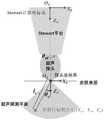
图6是本申请优选实施例的超声探测装置的探头坐标系与Stewart计算坐标系的示意图。在超声探测装置与Stewart动平台之间设有一个旋转电机,电机的旋转角度记为θm。超声探测装置的末端点位于Stewart动平台坐标系的Z轴上,无论θm取何值,超声探测装置的末端点相对Stewart动平台的位置都是不变。FIG. 6 is a schematic diagram of a probe coordinate system and a Stewart calculation coordinate system of an ultrasonic detection device according to a preferred embodiment of the present application. A rotary motor is arranged between the ultrasonic detection device and the Stewart moving platform, and the rotation angle of the motor is recorded as θm . The end point of the ultrasonic detection device is located on the Z axis of the Stewart moving platform coordinate system. No matter what the value of θm is, the position of the end point of the ultrasonic detection device relative to the Stewart moving platform remains unchanged.
在超声探测装置末端建立探头坐标系,探头坐标系的原点与探头末端点重合,且忽略Stewart动平台与超声探测装置之间的旋转电机的运动,默认探头坐标系的XYZ轴始终与Stewart动平台坐标系的XYZ轴平行。也就是将Stewart动平台与超声探测装置之间的电机的旋转量θm视为超声探测平面相对探头坐标系的运动。A probe coordinate system is established at the end of the ultrasonic detection device. The origin of the probe coordinate system coincides with the end point of the probe, and the motion of the rotating motor between the Stewart moving platform and the ultrasonic detection device is ignored. By default, the XYZ axis of the probe coordinate system is always the same as the Stewart moving platform. The XYZ axes of the coordinate system are parallel. That is, the rotation amount θm of the motor between the Stewart moving platform and the ultrasonic detection device is regarded as the movement of the ultrasonic detection plane relative to the probe coordinate system.
需要说明的是,探头坐标系的建立方式并不是唯一的,并不一定要将探头相对于Stewart动平台的转动θm转化为超声探测平面相对于探头坐标系的转动。It should be noted that the establishment of the probe coordinate system is not unique, and it is not necessary to convert the rotation θm of the probe relative to the Stewart moving platform into the rotation of the ultrasonic detection plane relative to the probe coordinate system.
在通过主从映射方法控制Stewart并联平台的情况下,超声探头的运动可以由主操作手控制,例如通过混联主从映射算法将主操作手在竖直方向上的运动量映射到并联平台,将主操作手的水平平面内的运动量映射到串联机械臂。通过混联主从映射算法可得超声探测装置末端点在Stewart计算坐标系的位置Ccoord_det_st(三维列向量),和探头坐标系相对于Stewart计算坐标系的姿态角


其中Rcoord_det_st为旋转矩阵,用姿态角

操作者可以通过主操作手操控末端安装有超声探测装置的机械臂,使穿刺目标靶点位于超声探测平面(声束平面)上。超声探测平面为经过超声探测装置末端点且垂直于探头坐标系XY平面的一个平面,在超声探测平面内的任意一点可测得其相对于探头坐标系的距离lc和与Z轴的夹角θc。The operator can control the mechanical arm with the ultrasonic detection device installed at the end through the main operator, so that the puncture target is located on the ultrasonic detection plane (sound beam plane). The ultrasonic detection plane is a plane that passes through the end point of the ultrasonic detection device and is perpendicular to the XY plane of the probe coordinate system. At any point in the ultrasonic detection plane, the distance lc relative to the probe coordinate system and the included angle with the Z axis can be measured. θc .
通过lc,θc,θm这三个已知量,可知穿刺目标靶点在探头坐标系下的坐标Sst(Xst,Yst,Zst),记为Ccoord_tar_det。Through the three known quantities of lc , θc , and θm , the coordinates Sst (Xst, Yst, Zst) of the puncture target in the probe coordinate system can be known, which is denoted as Ccoord_tar_det .
Ccoord_tar_det=[lcsinθccosθm lcsinθcsinθm lccosθc 1]T。Ccoord_tar_det =[lc sinθc cosθm lc sinθc sinθm lc cosθc 1]T .
通过坐标转换可得目标靶点在机械坐标系下的坐标Ccoord_tar_mach:The coordinate Ccoord_tar_mach of the target point in the mechanical coordinate system can be obtained by coordinate transformation:
Ccoord_tar_mach=Ttrans_mach_stTtrans_st_detCcoord_tar_det。Ccoord_tar_mach =Ttrans_mach_st Ttrans_st_det Ccoord_tar_det .
在其中的一些实施例中,超声定位穿刺系统还包括第二串联机械臂和搭载在第二串联机械臂末端的穿刺器械;计算机设备还分别与第二串联机械臂电性连接,处理器在运行计算机程序时还执行下列步骤:将靶点在参考坐标系内的第二位置信息作为目标穿刺点,控制第二串联机械臂的穿刺器械对目标穿刺点进行穿刺。In some of the embodiments, the ultrasonic positioning and puncturing system further includes a second serial robotic arm and a puncturing instrument mounted on the end of the second serial robotic arm; the computer equipment is also electrically connected to the second serial robotic arm, and the processor is running The computer program also executes the following steps: taking the second position information of the target in the reference coordinate system as the target puncture point, and controlling the puncture instrument of the second serial robotic arm to puncture the target puncture point.
通过坐标转换可得目标靶点在穿刺机械臂Stewart计算坐标系下的坐标Ccoord_tar_stl:The coordinate Ccoord_tar_stl of the target point in the coordinate system calculated by Stewart of the puncture manipulator can be obtained through coordinate transformation:
Ccoord_tar_stl=Ttrans_stl_machCcoord_tar_mach。Ccoord_tar_stl =Ttrans_stl_mach Ccoord_tar_mach .
其中Ttrans_stl_mach为穿刺机械臂Stewart计算坐标系到计算坐标系的转换矩阵。Among them, Ttrans_stl_mach is the transformation matrix from the calculated coordinate system of the puncture manipulator Stewart to the calculated coordinate system.
已知目标靶点在穿刺机械臂Stewart计算坐标系下的坐标以及预设的穿刺路径和穿刺速度,即可通过Stewart并联平台的逆运动学解算穿刺机械臂Stewart平台的关节运动量,用穿刺机械臂进行精准的穿刺。Knowing the coordinates of the target point in the coordinate system calculated by the puncture manipulator Stewart, as well as the preset puncture path and puncture speed, the joint motion of the Stewart platform of the puncture manipulator can be calculated through the inverse kinematics of the Stewart parallel platform. Arm for precise puncture.
通过上述具有两个机械臂的系统,第一串联机械臂的末端搭载超声探测装置,第二串联机械臂的末端搭载穿刺器械,穿刺消融手术的执行由两个机械臂协作完成,第一串联机械臂持超声探头,在人体表面扫描寻找病灶,并定位穿刺目标靶点,可以实现靶点的精准定位。第二串联机械臂持消融针,对目标靶点进行穿刺消融,可以实现对靶点的精准穿刺。整个定位和穿刺的过程几乎对人为操作的依赖性较小,更加安全,并且上述靶点定位和穿刺方法兼容现有的具有多机械臂且机械臂末端设置有并联平台的机器人,不需要独立开发复杂的系统。Through the above system with two robotic arms, the end of the first serial robotic arm is equipped with an ultrasonic detection device, and the end of the second serial robotic arm is equipped with a puncture instrument, the execution of the puncture and ablation operation is completed by the cooperation of the two robotic arms, and the first serial The arm holds the ultrasound probe, scans the surface of the human body to find the lesions, and locates the puncture target, which can achieve precise positioning of the target. The second serial robotic arm holds the ablation needle and performs puncture and ablation on the target point, which can achieve precise puncture of the target point. The whole process of positioning and puncturing is almost less dependent on human operation and is safer, and the above-mentioned target positioning and puncturing methods are compatible with existing robots with multiple manipulators and a parallel platform at the end of the manipulator, and no independent development is required. complex system.
另外,结合上述实施例中的方法,本申请实施例还提供一种计算机可读存储介质来实现。该计算机可读存储介质上存储有计算机程序;计算机程序被设置为运行时执行下列步骤:In addition, in combination with the methods in the foregoing embodiments, the embodiments of the present application further provide a computer-readable storage medium for implementation. A computer program is stored on the computer-readable storage medium; the computer program is configured to execute the following steps when running:
S1,在超声探测装置投射的超声探测平面内定位靶点的第一位置信息。S1, locate the first position information of the target in the ultrasonic detection plane projected by the ultrasonic detection device.
S2,获取超声探测平面的第一姿态信息以及第一串联机械臂的第二姿态信息。S2: Acquire first attitude information of the ultrasonic detection plane and second attitude information of the first serial manipulator.
S3,根据第一姿态信息和第二姿态信息,确定超声定位穿刺系统的参考坐标系与超声探测平面所在坐标系的位置转换关系。S3, according to the first attitude information and the second attitude information, determine the position conversion relationship between the reference coordinate system of the ultrasonic positioning puncture system and the coordinate system where the ultrasonic detection plane is located.
S4,根据位置转换关系和第一位置信息,确定靶点在参考坐标系内的第二位置信息。S4, according to the position conversion relationship and the first position information, determine the second position information of the target point in the reference coordinate system.
在其中一些实施例中,在超声探测装置投射的超声探测平面内定位靶点的第一位置信息包括:获取由超声探测装置采集的超声图像,在超声图像中定位靶点的位置信息;根据靶点在超声图像中的位置信息以及超声探测装置的标定参数,确定靶点在超声探测装置投射的超声探测平面内的第一位置信息。In some of these embodiments, locating the first position information of the target point in the ultrasonic detection plane projected by the ultrasonic detection device includes: acquiring an ultrasonic image collected by the ultrasonic detection device, and locating the position information of the target point in the ultrasonic image; The position information of the point in the ultrasonic image and the calibration parameters of the ultrasonic detection device determine the first position information of the target point in the ultrasonic detection plane projected by the ultrasonic detection device.
在其中一些实施例中,第一位置信息包括靶点相对于末端端点的距离,以及靶点和末端端点的连接线与旋转轴的夹角。In some of the embodiments, the first position information includes the distance of the target point relative to the end point, and the angle between the connecting line between the target point and the end point and the rotation axis.
在其中一些实施例中,根据第一姿态信息和第二姿态信息,确定超声定位穿刺系统的参考坐标系与超声探测平面所在坐标系的位置转换关系包括:在第一串联机械臂处于初始状态时,建立第一串联机械臂的参考坐标系和第一串联机械臂的各关节的关节坐标系,以及在超声探测装置处于初始状态时,以超声探测装置的末端端点为坐标原点建立探头坐标系;获取第一串联机械臂的参考坐标系和第一串联机械臂的各关节的关节坐标系的DH参数,并根据DH参数,确定第一串联机械臂的参考坐标系到第一串联机械臂的末端关节的关节坐标系之间的第一位置转换关系;获取探头坐标系的坐标原点在末端关节的关节坐标系内的位置信息,以及探头坐标系相对于末端关节的关节坐标系的姿态角,并根据该位置信息、姿态角以及第一位置转换关系,确定参考坐标系与探头坐标系之间的第二位置转换关系;获取超声探测平面的旋转角度,并根据旋转角度确定超声探测平面所在坐标系与探头坐标系之间的第三位置转换关系;根据第二位置转换关系和第三位置转换关系,确定超声定位穿刺系统的参考坐标系与超声探测平面所在坐标系的位置转换关系。In some of the embodiments, according to the first attitude information and the second attitude information, determining the position conversion relationship between the reference coordinate system of the ultrasonic positioning and puncturing system and the coordinate system where the ultrasonic detection plane is located includes: when the first serial robotic arm is in an initial state , establish the reference coordinate system of the first serial manipulator and the joint coordinate system of each joint of the first serial manipulator, and when the ultrasonic detection device is in the initial state, establish the probe coordinate system with the end point of the ultrasonic detection device as the coordinate origin; Obtain the reference coordinate system of the first serial manipulator and the DH parameters of the joint coordinate system of each joint of the first serial manipulator, and determine the reference coordinate system of the first serial manipulator to the end of the first serial manipulator according to the DH parameters The first position conversion relationship between the joint coordinate systems of the joints; obtain the position information of the coordinate origin of the probe coordinate system in the joint coordinate system of the end joint, and the attitude angle of the probe coordinate system relative to the joint coordinate system of the end joint, and According to the position information, the attitude angle and the first position conversion relationship, determine the second position conversion relationship between the reference coordinate system and the probe coordinate system; obtain the rotation angle of the ultrasonic detection plane, and determine the coordinate system where the ultrasonic detection plane is located according to the rotation angle The third position conversion relationship with the probe coordinate system; according to the second position conversion relationship and the third position conversion relationship, the position conversion relationship between the reference coordinate system of the ultrasonic positioning puncture system and the coordinate system where the ultrasonic detection plane is located is determined.
在其中一些实施例中,第一串联机械臂包括旋转关节和移动关节,旋转关节的关节坐标系的Z轴沿旋转轴设置,移动关节的关节坐标系的Z轴沿移动方向设置,参考坐标系与各关节的关节坐标系同为左手系或右手系,且当旋转关节与在前的移动关节连接时,旋转关节的关节坐标系的原点与该在前的移动关节的关节坐标系的原点重合。In some of these embodiments, the first serial manipulator includes a rotating joint and a moving joint, the Z axis of the joint coordinate system of the rotating joint is set along the rotating axis, the Z axis of the joint coordinate system of the moving joint is set along the moving direction, and the reference coordinate system The joint coordinate system of each joint is the same as the left-handed or right-handed system, and when the rotary joint is connected to the previous mobile joint, the origin of the joint coordinate system of the rotary joint coincides with the origin of the joint coordinate system of the previous mobile joint .
在其中一些实施例中,探头坐标系的X、Y、Z轴的方向与末端关节的关节坐标系的X、Y、Z轴的方向相同,且探头坐标系的Z轴和末端关节的关节坐标系的Z轴共线。In some of these embodiments, the directions of the X, Y, and Z axes of the probe coordinate system are the same as the directions of the X, Y, and Z axes of the joint coordinate system of the end joint, and the Z axis of the probe coordinate system and the joint coordinates of the end joint The Z axis of the system is collinear.
在其中一些实施例中,计算机程序还被设置为运行时执行下列步骤:将靶点在参考坐标系内的第二位置信息作为目标穿刺点,控制第二串联机械臂的穿刺器械对目标穿刺点进行穿刺。In some of the embodiments, the computer program is further configured to execute the following steps when running: use the second position information of the target point in the reference coordinate system as the target puncture point, and control the puncture instrument of the second serial robotic arm to puncture the target puncture point Perform puncture.
需要说明的是,本实施例中的具体示例可以参考上述实施例及可选实施方式中所描述的示例,本实施例在此不再赘述。It should be noted that, for specific examples in this embodiment, reference may be made to the examples described in the foregoing embodiments and optional implementation manners, and details are not described herein again in this embodiment.
本领域的技术人员应该明白,以上所述实施例的各技术特征可以进行任意的组合,为使描述简洁,未对上述实施例中的各个技术特征所有可能的组合都进行描述,然而,只要这些技术特征的组合不存在矛盾,都应当认为是本说明书记载的范围。Those skilled in the art should understand that the technical features of the above-described embodiments can be combined arbitrarily. For the sake of brevity, all possible combinations of the technical features of the above-described embodiments are not described. There is no contradiction in the combination of technical features, and it should be regarded as the scope of the description in this specification.
以上所述实施例仅表达了本申请的几种实施方式,其描述较为具体和详细,但并不能因此而理解为对发明专利范围的限制。应当指出的是,对于本领域的普通技术人员来说,在不脱离本申请构思的前提下,还可以做出若干变形和改进,这些都属于本申请的保护范围。因此,本申请专利的保护范围应以所附权利要求为准。The above-mentioned embodiments only represent several embodiments of the present application, and the descriptions thereof are specific and detailed, but should not be construed as a limitation on the scope of the invention patent. It should be pointed out that for those skilled in the art, without departing from the concept of the present application, several modifications and improvements can be made, which all belong to the protection scope of the present application. Therefore, the scope of protection of the patent of the present application shall be subject to the appended claims.
Claims (10)
Priority Applications (1)
| Application Number | Priority Date | Filing Date | Title |
|---|---|---|---|
| CN202011610690.4ACN112754616B (en) | 2020-12-30 | 2020-12-30 | Ultrasonic positioning puncture system and storage medium |
Applications Claiming Priority (1)
| Application Number | Priority Date | Filing Date | Title |
|---|---|---|---|
| CN202011610690.4ACN112754616B (en) | 2020-12-30 | 2020-12-30 | Ultrasonic positioning puncture system and storage medium |
Publications (2)
| Publication Number | Publication Date |
|---|---|
| CN112754616A CN112754616A (en) | 2021-05-07 |
| CN112754616Btrue CN112754616B (en) | 2022-05-10 |
Family
ID=75695934
Family Applications (1)
| Application Number | Title | Priority Date | Filing Date |
|---|---|---|---|
| CN202011610690.4AActiveCN112754616B (en) | 2020-12-30 | 2020-12-30 | Ultrasonic positioning puncture system and storage medium |
Country Status (1)
| Country | Link |
|---|---|
| CN (1) | CN112754616B (en) |
Families Citing this family (9)
| Publication number | Priority date | Publication date | Assignee | Title |
|---|---|---|---|---|
| CN115211970A (en)* | 2021-06-11 | 2022-10-21 | 诺创智能医疗科技(杭州)有限公司 | Pose transformation method and system of mechanical arm and mechanical arm assembly |
| CN113349939B (en)* | 2021-07-12 | 2023-03-21 | 哈尔滨思哲睿智能医疗设备股份有限公司 | Performance test method and system for passive active hand type master-slave control surgical robot |
| CN113749694B (en)* | 2021-10-11 | 2023-08-15 | 上海交通大学医学院附属第九人民医院 | Puncture biopsy and ablation system |
| CN114271911A (en)* | 2021-12-17 | 2022-04-05 | 领汇医疗科技(武汉)有限公司 | A puncture target, targeted puncture positioning device and method |
| CN114714349B (en)* | 2022-03-23 | 2024-04-16 | 武汉库柏特科技有限公司 | A remote-operated ultrasonic scanning robot posture testing method, device and equipment |
| CN115462901A (en)* | 2022-10-20 | 2022-12-13 | 哈尔滨思哲睿智能医疗设备股份有限公司 | Operation real-time navigation method, device, system, equipment and medium |
| CN116619327B (en)* | 2023-07-24 | 2023-09-19 | 成都盛锴科技有限公司 | Combined type railway vehicle part image acquisition robot and method |
| CN119655841B (en)* | 2025-02-19 | 2025-05-30 | 卡本(深圳)医疗器械有限公司 | Ultrasonic positioning puncture system and storage medium |
| CN120036897B (en)* | 2025-04-25 | 2025-07-22 | 中南大学湘雅二医院 | A five-degree-of-freedom puncture robot and control method |
Citations (8)
| Publication number | Priority date | Publication date | Assignee | Title |
|---|---|---|---|---|
| CN102105190A (en)* | 2008-05-28 | 2011-06-22 | 泰克尼恩研究和发展基金有限公司 | Ultrasound-guided robotics for flexible needle manipulation |
| CN104856720A (en)* | 2015-05-07 | 2015-08-26 | 东北电力大学 | Auxiliary ultrasonic scanning system of robot based on RGB-D sensor |
| DE102014216944A1 (en)* | 2014-08-26 | 2016-03-03 | Siemens Aktiengesellschaft | Medical examination device and method for registration of imaging devices |
| CN109549705A (en)* | 2019-01-21 | 2019-04-02 | 华科精准(北京)医疗科技有限公司 | A surgical robot system and method of using the same |
| CN109938768A (en)* | 2019-03-11 | 2019-06-28 | 深圳市比邻星精密技术有限公司 | Ultrasonic imaging method, device, computer equipment and storage medium |
| CN110353774A (en)* | 2018-12-15 | 2019-10-22 | 深圳铭杰医疗科技有限公司 | Assist Needle-driven Robot and its control method, computer equipment, storage medium |
| CN110559077A (en)* | 2018-06-05 | 2019-12-13 | 上海联影医疗科技有限公司 | Coordinate system registration method, robot control method, device, equipment and medium |
| CN111956329A (en)* | 2020-08-12 | 2020-11-20 | 中国科学院深圳先进技术研究院 | Calibration method, system, terminal and storage medium for double-arm robot |
Family Cites Families (21)
| Publication number | Priority date | Publication date | Assignee | Title |
|---|---|---|---|---|
| JP3937108B2 (en)* | 1997-07-18 | 2007-06-27 | 株式会社安川電機 | Robot control method and robot |
| US7904202B2 (en)* | 2004-10-25 | 2011-03-08 | University Of Dayton | Method and system to provide improved accuracies in multi-jointed robots through kinematic robot model parameters determination |
| DE102010020350B4 (en)* | 2010-05-12 | 2017-02-23 | Siemens Healthcare Gmbh | Method for positioning the focus of a gradient field and treatment device |
| CN102794763B (en)* | 2012-08-31 | 2014-09-24 | 江南大学 | Calibration method of welding robot system based on line structured light vision sensor guidance |
| KR102470468B1 (en)* | 2014-03-17 | 2022-11-25 | 인튜어티브 서지컬 오퍼레이션즈 인코포레이티드 | System and method for aligning with a reference target |
| WO2015161297A1 (en)* | 2014-04-17 | 2015-10-22 | The Johns Hopkins University | Robot assisted ultrasound system |
| WO2016069663A1 (en)* | 2014-10-27 | 2016-05-06 | Intuitive Surgical Operations, Inc. | System and method for integrated surgical table motion |
| WO2016082019A1 (en)* | 2014-11-25 | 2016-06-02 | Synaptive Medical (Barbados) Inc. | Hand guided automated positioning device controller |
| WO2016092461A1 (en)* | 2014-12-09 | 2016-06-16 | Koninklijke Philips N.V. | Positioning electromagnetic field generators for interventional procedures |
| JP6504864B2 (en)* | 2015-03-13 | 2019-04-24 | キヤノン株式会社 | Robot control method, robot apparatus, program, recording medium, and article manufacturing method |
| CN104858870A (en)* | 2015-05-15 | 2015-08-26 | 江南大学 | Industrial robot measurement method based on tail end numbered tool |
| GB201509341D0 (en)* | 2015-05-29 | 2015-07-15 | Cambridge Medical Robotics Ltd | Characterising robot environments |
| CN111329553B (en)* | 2016-03-12 | 2021-05-04 | P·K·朗 | Devices and methods for surgery |
| US11446104B2 (en)* | 2017-10-26 | 2022-09-20 | Cilag Gmbh International | Manual release assembly for robotic surgical tool |
| CN107811710B (en)* | 2017-10-31 | 2019-09-17 | 微创(上海)医疗机器人有限公司 | Operation aided positioning system |
| CN107928805B (en)* | 2017-12-06 | 2019-04-26 | 上海波城医疗科技有限公司 | Ultrasonic scanning space positioning system and method |
| CN109278044A (en)* | 2018-09-14 | 2019-01-29 | 合肥工业大学 | A method of hand-eye calibration and coordinate conversion |
| US20220110685A1 (en)* | 2019-02-05 | 2022-04-14 | Smith & Nephew, Inc. | Methods for improving robotic surgical systems and devices thereof |
| US10576636B1 (en)* | 2019-04-12 | 2020-03-03 | Mujin, Inc. | Method and control system for and updating camera calibration for robot control |
| CN111012506B (en)* | 2019-12-28 | 2021-07-27 | 哈尔滨工业大学 | Robot-assisted puncture surgery end tool center calibration method based on stereo vision |
| CN112025772B (en)* | 2020-07-28 | 2021-11-23 | 沈阳建筑大学 | Mechanical arm autonomous calibration method based on visual measurement |
- 2020
- 2020-12-30CNCN202011610690.4Apatent/CN112754616B/enactiveActive
Patent Citations (8)
| Publication number | Priority date | Publication date | Assignee | Title |
|---|---|---|---|---|
| CN102105190A (en)* | 2008-05-28 | 2011-06-22 | 泰克尼恩研究和发展基金有限公司 | Ultrasound-guided robotics for flexible needle manipulation |
| DE102014216944A1 (en)* | 2014-08-26 | 2016-03-03 | Siemens Aktiengesellschaft | Medical examination device and method for registration of imaging devices |
| CN104856720A (en)* | 2015-05-07 | 2015-08-26 | 东北电力大学 | Auxiliary ultrasonic scanning system of robot based on RGB-D sensor |
| CN110559077A (en)* | 2018-06-05 | 2019-12-13 | 上海联影医疗科技有限公司 | Coordinate system registration method, robot control method, device, equipment and medium |
| CN110353774A (en)* | 2018-12-15 | 2019-10-22 | 深圳铭杰医疗科技有限公司 | Assist Needle-driven Robot and its control method, computer equipment, storage medium |
| CN109549705A (en)* | 2019-01-21 | 2019-04-02 | 华科精准(北京)医疗科技有限公司 | A surgical robot system and method of using the same |
| CN109938768A (en)* | 2019-03-11 | 2019-06-28 | 深圳市比邻星精密技术有限公司 | Ultrasonic imaging method, device, computer equipment and storage medium |
| CN111956329A (en)* | 2020-08-12 | 2020-11-20 | 中国科学院深圳先进技术研究院 | Calibration method, system, terminal and storage medium for double-arm robot |
Also Published As
| Publication number | Publication date |
|---|---|
| CN112754616A (en) | 2021-05-07 |
Similar Documents
| Publication | Publication Date | Title |
|---|---|---|
| CN112754616B (en) | Ultrasonic positioning puncture system and storage medium | |
| WO2022141153A1 (en) | Ultrasonic positioning puncture system and storage medium | |
| CN113133832B (en) | A method and system for calibrating a dual-arm robot puncture system | |
| WO2022218389A1 (en) | Ultrasonic and x-ray combined execution operation method, device and system, and computer-readable storage medium | |
| CN114631886B (en) | Robotic arm positioning method, readable storage medium and surgical robot system | |
| JP7383489B2 (en) | Integration of robotic device guidance and acoustic probes | |
| CN115105175B (en) | Puncture navigation system, method, device, storage medium and puncture device | |
| CN113456220B (en) | Alignment method, surgical robot, and computer storage medium | |
| CN112828885B (en) | Hybrid master-slave mapping method, robotic arm system and computer equipment | |
| CN117084790B (en) | Puncture azimuth control method and device, computer equipment and storage medium | |
| CN111603205A (en) | Three-dimensional image reconstruction and positioning analysis system used in CT (computed tomography) cabin of puncture surgical robot | |
| WO2022141138A1 (en) | Hybrid master-slave mapping method, robotic arm system, and computer device | |
| WO2022198615A1 (en) | Calibration method and system for dual-arm robot puncture system | |
| CN117084791B (en) | Puncture azimuth resolving method and puncture operation executing system | |
| CN116236288B (en) | Miniature puncture robot, puncture system and puncture control model | |
| CN115778445A (en) | A verification method for laser guidance at the end of a robotic arm | |
| Azimi et al. | Teleoperative control of intraocular robotic snake: Vision-based angular calibration | |
| JP7500272B2 (en) | Registration method, registration program, and puncture system | |
| CN115153782A (en) | Puncture robot space registration method under ultrasonic guidance | |
| JPWO2022043896A5 (en) | ||
| CN119655841B (en) | Ultrasonic positioning puncture system and storage medium | |
| CN119587162B (en) | A method, device, system and computer program product for navigation and positioning | |
| US20250288361A1 (en) | Generating imaging pose recommendations | |
| US20250302543A1 (en) | Registration of imaging system with sensor system for instrument navigation | |
| Yoshida et al. | Image plane positioning by pneumatic actuators for ultrasound guidance |
Legal Events
| Date | Code | Title | Description |
|---|---|---|---|
| PB01 | Publication | ||
| PB01 | Publication | ||
| SE01 | Entry into force of request for substantive examination | ||
| SE01 | Entry into force of request for substantive examination | ||
| GR01 | Patent grant | ||
| GR01 | Patent grant | ||
| PP01 | Preservation of patent right | ||
| PP01 | Preservation of patent right | Effective date of registration:20241209 Granted publication date:20220510 |