CN112734652B - Near-infrared blood vessel image projection correction method based on binocular vision - Google Patents
Near-infrared blood vessel image projection correction method based on binocular visionDownload PDFInfo
- Publication number
- CN112734652B CN112734652BCN202011530678.2ACN202011530678ACN112734652BCN 112734652 BCN112734652 BCN 112734652BCN 202011530678 ACN202011530678 ACN 202011530678ACN 112734652 BCN112734652 BCN 112734652B
- Authority
- CN
- China
- Prior art keywords
- image
- pixel
- coordinate system
- points
- blood vessel
- Prior art date
- Legal status (The legal status is an assumption and is not a legal conclusion. Google has not performed a legal analysis and makes no representation as to the accuracy of the status listed.)
- Active
Links
Images


Classifications
- G—PHYSICS
- G06—COMPUTING OR CALCULATING; COUNTING
- G06T—IMAGE DATA PROCESSING OR GENERATION, IN GENERAL
- G06T5/00—Image enhancement or restoration
- G06T5/80—Geometric correction
- G—PHYSICS
- G06—COMPUTING OR CALCULATING; COUNTING
- G06T—IMAGE DATA PROCESSING OR GENERATION, IN GENERAL
- G06T17/00—Three dimensional [3D] modelling, e.g. data description of 3D objects
- G—PHYSICS
- G06—COMPUTING OR CALCULATING; COUNTING
- G06T—IMAGE DATA PROCESSING OR GENERATION, IN GENERAL
- G06T7/00—Image analysis
- G06T7/80—Analysis of captured images to determine intrinsic or extrinsic camera parameters, i.e. camera calibration
- G06T7/85—Stereo camera calibration
- G—PHYSICS
- G06—COMPUTING OR CALCULATING; COUNTING
- G06T—IMAGE DATA PROCESSING OR GENERATION, IN GENERAL
- G06T2207/00—Indexing scheme for image analysis or image enhancement
- G06T2207/10—Image acquisition modality
- G06T2207/10028—Range image; Depth image; 3D point clouds
- G—PHYSICS
- G06—COMPUTING OR CALCULATING; COUNTING
- G06T—IMAGE DATA PROCESSING OR GENERATION, IN GENERAL
- G06T2207/00—Indexing scheme for image analysis or image enhancement
- G06T2207/10—Image acquisition modality
- G06T2207/10048—Infrared image
- G—PHYSICS
- G06—COMPUTING OR CALCULATING; COUNTING
- G06T—IMAGE DATA PROCESSING OR GENERATION, IN GENERAL
- G06T2207/00—Indexing scheme for image analysis or image enhancement
- G06T2207/20—Special algorithmic details
- G06T2207/20112—Image segmentation details
- G06T2207/20164—Salient point detection; Corner detection
- G—PHYSICS
- G06—COMPUTING OR CALCULATING; COUNTING
- G06T—IMAGE DATA PROCESSING OR GENERATION, IN GENERAL
- G06T2207/00—Indexing scheme for image analysis or image enhancement
- G06T2207/30—Subject of image; Context of image processing
- G06T2207/30004—Biomedical image processing
- G06T2207/30101—Blood vessel; Artery; Vein; Vascular
Landscapes
- Engineering & Computer Science (AREA)
- Physics & Mathematics (AREA)
- General Physics & Mathematics (AREA)
- Theoretical Computer Science (AREA)
- Computer Graphics (AREA)
- Geometry (AREA)
- Software Systems (AREA)
- Computer Vision & Pattern Recognition (AREA)
- Image Analysis (AREA)
- Measurement Of The Respiration, Hearing Ability, Form, And Blood Characteristics Of Living Organisms (AREA)
Abstract
Description
Translated fromChinese技术领域technical field
本发明涉及静脉穿刺的图像识别领域,尤其是涉及一种基于双目视觉的近红外血管图像投影校正方法。The invention relates to the field of image recognition of venipuncture, in particular to a near-infrared blood vessel image projection correction method based on binocular vision.
背景技术Background technique
在静脉穿刺的血管成像过程中,近红外光成像技术仍然是应用最为广泛的成像技术。其利用静脉血管中血红蛋白对近红外光的吸收作用,来获取静脉血管图像;其获取的图像再经过二值化、滤波、图像增强等一系列图像处理技术处理,最终投影到皮肤表面,便可看到较为清晰的静脉血管图像。但在实际的投影过程中,由于皮肤表面并非平面,而是由一系列圆滑曲面所构成,所以在投影的过程当中会产生一系列的图像扭曲畸变。因此,最终在人皮肤上所形成血管图像往往会发生一系列的扭曲畸变,对最终的穿刺引导造成较大的误差。In the vascular imaging process of venipuncture, near-infrared light imaging technology is still the most widely used imaging technology. It uses the absorption of near-infrared light by hemoglobin in veins to obtain images of veins; the acquired images are processed by a series of image processing technologies such as binarization, filtering, and image enhancement, and finally projected onto the skin surface. See clearer images of veins and blood vessels. However, in the actual projection process, since the skin surface is not flat, but is composed of a series of smooth curved surfaces, a series of image distortions will be generated during the projection process. Therefore, a series of distortions often occur in the final vascular image formed on the human skin, which causes large errors in the final puncture guidance.
发明内容Contents of the invention
本发明的目的就是为了克服上述现有技术存在的缺陷而提供一种基于双目视觉的近红外血管图像投影校正方法,克服近红外血管图像投影至皮肤表面时,由于皮肤非平面所带来的畸变失真,从而提高穿刺的成功率。The purpose of the present invention is to provide a near-infrared blood vessel image projection correction method based on binocular vision in order to overcome the above-mentioned defects in the prior art, to overcome the problem caused by the non-planar skin when the near-infrared blood vessel image is projected onto the skin surface. Distortion and distortion, thereby improving the success rate of puncture.
本发明的目的可以通过以下技术方案来实现:The purpose of the present invention can be achieved through the following technical solutions:
一种基于双目视觉的近红外血管图像投影校正方法,包括以下步骤:A method for projecting correction of near-infrared blood vessel images based on binocular vision, comprising the following steps:
S1、通过近红外采集装置获得当前皮肤位置血管图像P0;S1. Obtain the blood vessel image P0 at the current skin position through the near-infrared acquisition device;
S2、利用双目相机移动多个位置拍摄相同皮肤位置的图像,双目相机每移动一次位置进行一次参数标定;S2. Use the binocular camera to move multiple positions to take images of the same skin position, and perform a parameter calibration every time the binocular camera moves a position;
S3、通过在双目相机所拍摄的每一张图像上不断移动窗口位置来寻找Harris 算子的极值,当该极值大于给定阈值时,即认定当前像素点为该图像的特征点 Pn(m),n表示图像的序号,m表示特征点的序号;S3. Find the extreme value of the Harris operator by continuously moving the window position on each image captured by the binocular camera. When the extreme value is greater than a given threshold, the current pixel is identified as the feature point P of the image.n (m), n represents the sequence number of the image, and m represents the sequence number of the feature point;
S4、利用NCC算法对步骤S3中所得到的不同图像的特征点Pn(m)进行两两匹配,当通过NCC匹配度公式计算得到的匹配度系数大于设定阈值时,认定两个特征点匹配,从而建立起配对的track组合;S4. Use the NCC algorithm to perform pairwise matching on the feature points Pn (m) of different images obtained in step S3. When the matching degree coefficient calculated by the NCC matching degree formula is greater than the set threshold, two feature points are identified. match, thus establishing a paired track combination;
S5、计算每一个track中的特征点的实际三维坐标,并利用最小二乘法将每一个track中的计算所得点连接成为3D点云模型;S5. Calculate the actual three-dimensional coordinates of the feature points in each track, and use the least squares method to connect the calculated points in each track to form a 3D point cloud model;
S6、通过最近点迭代的ICP算法完成3D点云模型匹配重构出皮肤3D表面模型;S6. Complete the 3D point cloud model matching and reconstruct the skin 3D surface model through the nearest point iterative ICP algorithm;
S7、利用步骤S6中所得到的皮肤3D曲面模型的曲率信息对血管图像P0进行扭曲还原处理,最终得到处理后的图像;S7. Using the curvature information of the skin 3D curved surface model obtained in step S6, the blood vessel imageP0 is distorted and restored, and finally the processed image is obtained;
S8、将处理后的近红外血管图像投影至皮肤表面。S8. Projecting the processed near-infrared blood vessel image onto the skin surface.
进一步地,所述的步骤S2中,利用双目相机光心、图像平面中的像素点和实际物体的位置关系来获取物体的深度信息同时完成摄像机的参数标定;Further, in the step S2, the depth information of the object is obtained by using the optical center of the binocular camera, the pixel points in the image plane and the positional relationship of the actual object, and the parameter calibration of the camera is completed at the same time;
所述世界坐标系用于描述摄像机的位置;The world coordinate system is used to describe the position of the camera;
所述图像坐标系包括原点在图像左上角的像素图像坐标系O-uv,以及原点在图像的几何中心位置的物理图像坐标系O-XY;The image coordinate system includes a pixel image coordinate system O-uv whose origin is at the upper left corner of the image, and a physical image coordinate system O-XY whose origin is at the geometric center of the image;
所述摄像机坐标系O-xyz即为以摄像机为中心位置,横纵轴与像素图坐标系平行,z轴则沿摄像机光心位置透过图像指向物体的坐标系;The camera coordinate system O-xyz is the camera as the center position, the horizontal and vertical axes are parallel to the pixel map coordinate system, and the z axis is the coordinate system pointing to the object through the image along the optical center position of the camera;
进行双目相机参数标定的表达式如下:The expression for binocular camera parameter calibration is as follows:
物理图像坐标系O-XY与摄像机坐标系O-xyz的关系式为:The relationship between the physical image coordinate system O-XY and the camera coordinate system O-xyz is:


其中,


双目相机的两个镜头的位置之间的关系表达式为:The relationship expression between the positions of the two lenses of the binocular camera is:

其中,x、y、z表示物体在实际空间中的三维坐标;r1~r9表示双目相机参数标定中需要标定的9个旋转矩阵参数的待定系数;tx、ty、tz表示双目相机参数标定中需要标定的3个平移矩阵参数的待定系数;R表示旋转矩阵;T表示平移矩阵;P 表示参数矩阵,反映了摄像机坐标系相对于世界坐标系的方向和位置参数等信息,求得P的过程即为摄像机的参数标定。Among them, x, y, and z represent the three-dimensional coordinates of the object in the actual space; r1~r9 represent the undetermined coefficients of the 9 rotation matrix parameters that need to be calibrated in the binocular camera parameter calibration; tx ,ty , tz represent the binocular The undetermined coefficients of the three translation matrix parameters that need to be calibrated in the camera parameter calibration; R represents the rotation matrix; T represents the translation matrix; P represents the parameter matrix, which reflects the direction and position parameters of the camera coordinate system relative to the world coordinate system. The process of obtaining P is the parameter calibration of the camera.
进一步地,所述的步骤S3具体包括:Further, the step S3 specifically includes:
S31、计算S2中所得每张图像的水平和垂直方向的梯度;S31. Calculate the horizontal and vertical gradients of each image obtained in S2;
S32、计算每个像素点位置的Harris矩阵;S32. Calculate the Harris matrix of each pixel position;
S33、计算每个像素点位置的Harris角点响应值;S33. Calculate the Harris corner response value of each pixel position;
S34、进行非极大值抑制:分别给定步骤S33中计算所得的每个窗口的置信度得分,窗口由3×3像素点构成,取窗口内9个像素点Harris角点响应值的算术均值为置信度,设定阈值0.75;依据置信度进行排序,并将置信度最高的窗口边界框中特征点选出;计算所有剩余特征点像素的面积之和;计算置信度最高的像素点及其周围候选像素点的IoU;删除IoU大于设定阈值的边界框;重复步骤S32~S34 直到边界框列表为空;S34. Perform non-maximum value suppression: given the confidence score of each window calculated in step S33 respectively, the window is composed of 3×3 pixels, and the arithmetic mean value of the Harris corner point response values of 9 pixels in the window is taken For the confidence level, set a threshold of 0.75; sort according to the confidence level, and select the feature points in the window boundary box with the highest confidence level; calculate the sum of the areas of all remaining feature point pixels; calculate the highest confidence level of the pixel point and its The IoU of the surrounding candidate pixels; delete the bounding box whose IoU is greater than the set threshold; repeat steps S32-S34 until the bounding box list is empty;
S35、找到Harris角点响应值大于给定阈值0.65的点作为特征点输出。S35. Find out the points whose Harris corner response value is greater than the given threshold 0.65 and output them as feature points.
进一步地,所述的步骤S4具体包括:Further, the step S4 specifically includes:
S41、对步骤S3所得到的每一个特征像素点(px,py)构建一个大小为n×n的邻域作为匹配窗口;S41. For each feature pixel point (px , py ) obtained in step S3, construct a neighborhood with a size of n×n as a matching window;
S42、对于相应待检测目标像素位置(px+d,py)同样构建一个大小为n×n的匹配窗口;S42. Construct a matching window with a size of n×n for the corresponding target pixel position (px +d, py ) to be detected;
S43、进行相似度匹配计算;S43. Perform similarity matching calculation;
S44、若步骤S43所计算的结果大于设定阈值,则认为两特征点匹配完成,否则,认为两特征点无强相关性。S44. If the calculated result in step S43 is greater than the set threshold, it is considered that the matching of the two feature points is completed; otherwise, it is considered that the two feature points have no strong correlation.
进一步地,所述相似度的计算表达式如下:Further, the calculation expression of the similarity is as follows:

其中,Hp为在步骤S4中所得到的需要匹配的特征点窗口;I1(x,y)为特征像素点的像素值;

进一步地,所述的步骤S7具体包括:Further, the step S7 specifically includes:
S71、依据步骤S6所得到的皮肤3D模型,可直接获得图像所对应像素点的曲率信息;S71. According to the skin 3D model obtained in step S6, the curvature information of the pixel corresponding to the image can be directly obtained;
S72、依据3D图像曲率信息,将全部特征点与血管图像P0一一对应;S72. According to the curvature information of the 3D image, one-to-one correspondence is made between all the feature points and the blood vessel imageP0 ;
S73、假设未进行畸变校正近红外图像像素在图像上所属坐标为(x,y),进行畸变校正后其相同像素的位置坐标为


通过步骤S72中得到的N个对应点,求出图像畸形校正系数a0~an,以及b0~bn。Image distortion correction coefficients a0 -an , and b0 -bn are calculated from the N corresponding points obtained in step S72 .
进一步地,步骤S1中,近红外采集装置获得当前皮肤位置血管图像后,通过高斯滤波去除噪点进行预处理。Further, in step S1, after the near-infrared acquisition device obtains the blood vessel image at the current skin position, it performs preprocessing by removing noise points through Gaussian filtering.
本发明是依据双目相机参数、特征点检测、特征匹配算法、空间点定位、表面几何重建等一系列变换后最终构建出曲面的3D表面模型。其中,在摄像机参数标定中采用三角测量方法;在图像特征提取中通过定义Harris算子,并寻找该算子的极值来提取图像的特征点;在特征点提取完成后利用NCC(Normalized Cross Correlation Method)对特征进行匹配;在特征点和匹配完成后,计算每一个track中的特征点的实际三维坐标,得点连接成为3D点云模型;并最终通过最近点迭代的 ICP(Iterative Closest Point)算法完成点云匹配重构出3D表面模型。The present invention finally constructs a 3D surface model of a curved surface after a series of transformations such as binocular camera parameters, feature point detection, feature matching algorithm, spatial point positioning, and surface geometry reconstruction. Among them, the triangulation method is used in the camera parameter calibration; in the image feature extraction, the feature points of the image are extracted by defining the Harris operator and looking for the extremum of the operator; after the feature point extraction is completed, the NCC (Normalized Cross Correlation Method) to match the features; after the feature points and the matching are completed, the actual three-dimensional coordinates of the feature points in each track are calculated, and the points are connected to form a 3D point cloud model; and finally through the ICP (Iterative Closest Point) algorithm of the nearest point iteration Complete the point cloud matching to reconstruct the 3D surface model.
与现有技术相比,本发明具有以下有益效果:Compared with the prior art, the present invention has the following beneficial effects:
本发明将基于双目视觉的3D曲面立体重建技术和图像扭曲畸变还原技术引入近红外血管成像的矫正当中,首先利用双目视觉的3D曲面立体重建技术得到皮肤表面的3D模型,从而获得指导图像扭曲畸变的曲面曲率等信息,并最终将畸变校正后的图像投影至皮肤表面,从而大大提高血管图像再次投影到皮肤表面上的精确性,从而大大提高静脉穿刺的准确率。The present invention introduces binocular vision-based 3D curved surface stereoscopic reconstruction technology and image distortion restoration technology into the correction of near-infrared vascular imaging, and first uses binocular vision 3D curved surface stereoscopic reconstruction technology to obtain a 3D model of the skin surface, thereby obtaining a guiding image Distort information such as the curvature of the distorted surface, and finally project the distortion-corrected image onto the skin surface, thereby greatly improving the accuracy of re-projecting the blood vessel image onto the skin surface, thereby greatly improving the accuracy of venipuncture.
附图说明Description of drawings
图1为本发明的流程示意图。Fig. 1 is a schematic flow chart of the present invention.
图2为世界坐标系、图像坐标系、摄像机坐标系的关系图。FIG. 2 is a relationship diagram of the world coordinate system, the image coordinate system, and the camera coordinate system.
图3为高斯核函数进行离散化处理时模板在各个位置坐标关系图。Fig. 3 is a coordinate diagram of the template at various positions when the Gaussian kernel function is discretized.
具体实施方式Detailed ways
下面结合附图和具体实施例对本发明进行详细说明。本实施例以本发明技术方案为前提进行实施,给出了详细的实施方式和具体的操作过程,但本发明的保护范围不限于下述的实施例。The present invention will be described in detail below in conjunction with the accompanying drawings and specific embodiments. This embodiment is carried out on the premise of the technical solution of the present invention, and detailed implementation and specific operation process are given, but the protection scope of the present invention is not limited to the following embodiments.
如图1所示,本实施例提供了一种基于双目视觉的近红外血管图像投影校正方法,包括以下步骤:As shown in FIG. 1 , this embodiment provides a binocular vision-based near-infrared blood vessel image projection correction method, including the following steps:
步骤S1、通过近红外采集装置获得当前皮肤位置血管图像,并通过高斯滤波对其进行图像预处理,去除图像噪点,将其获得图像记为P0。Step S1. Obtain the blood vessel image at the current skin position through the near-infrared acquisition device, perform image preprocessing on the image through Gaussian filtering, remove image noise, and denote the obtained image as P0 .
步骤S2、利用双目相机移动多个位置拍摄相同皮肤位置的图像(共拍摄n张图片,将其图片分别记为P1,P2,...Pn),双目相机每移动一次位置进行一次参数标定。Step S2, use the binocular camera to move multiple positions to take images of the same skin position (a total of n pictures are taken, and the pictures are recorded as P1 , P2 , ... Pn ), each time the binocular camera moves the position Perform a parameter calibration.
步骤S3、分别在双目摄像机所摄图像(P1,P2,...Pn)的每一张图像上不断移动窗口位置来寻找Harris算子的极值,当该极值大于给定阈值0.65时,即可认定其为该图像的特征点Pn(m),其代表意义是第n张双目摄像机所摄图像上的第m个特征点。Step S3, continuously move the window position on each image (P1 , P2 ,...Pn ) captured by the binocular camera to find the extremum value of the Harris operator, when the extremum value is greater than the given When the threshold is 0.65, it can be identified as the feature point Pn (m) of the image, and its representative meaning is the mth feature point on the image captured by the nth binocular camera.
步骤S4、利用NCC(Normalized Cross Correlation Method)算法对步骤S3中所得到的分属于不同图像的特征点Pn(m)进行两两匹配,当通过NCC匹配度公式计算得到的匹配度系数大于设定阈值0.75时,认定该两个特征点匹配;从而建立起配对的track组合比如(track1:P1(3)、P2(7)…代表P1图的第3个特征点和P2图的第 7个特征点匹配(是实际世界中相同的点只是在不同图片中位置不同))。Step S4, using the NCC (Normalized Cross Correlation Method) algorithm to perform pairwise matching on the feature points Pn (m) obtained in step S3 belonging to different images, when the matching degree coefficient calculated by the NCC matching degree formula is greater than the set When the threshold is set to 0.75, it is determined that the two feature points match; thereby establishing a paired track combination such as (track1:P1 (3), P2 (7)...represents the third feature point of the P1 map and the P2 map The 7th feature point matches (it is the same point in the actual world but the position is different in different pictures)).
步骤S5、计算每一个track中的特征点的实际三维坐标,并利用最小二乘法将每一个track中的计算所得点连接成为3D点云模型。Step S5, calculating the actual three-dimensional coordinates of the feature points in each track, and connecting the calculated points in each track to form a 3D point cloud model by using the least square method.
步骤S6、通过最近点迭代的ICP(Iterative Closest Point)算法完成点云匹配重构出3D表面模型。Step S6, complete the point cloud matching and reconstruct the 3D surface model through the iterative ICP (Iterative Closest Point) algorithm.
步骤S7、利用S6中所得到的3D曲面模型的曲率信息对血管图像P0进行扭曲还原处理,最终得到处理后的图像。Step S7, using the curvature information of the 3D curved surface model obtained in S6 to perform distortion restoration processing on the blood vessel imageP0 , and finally obtain a processed image.
步骤S8、将处理后的近红外血管图像投影至皮肤表面。Step S8, projecting the processed near-infrared blood vessel image onto the skin surface.
上述步骤的具体展开如下:The specific expansion of the above steps is as follows:
在步骤S1中,图像预处理采用高斯滤波去除噪点,其处理流程如下:In step S1, image preprocessing uses Gaussian filtering to remove noise, and its processing flow is as follows:
步骤S11:移动相关核的中心元素,使其位于输入图像待处理元素的正上方;其中一个二维的高斯核函数如下所示:Step S11: Move the central element of the relevant kernel so that it is directly above the element to be processed in the input image; one of the two-dimensional Gaussian kernel functions is as follows:

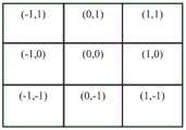
其中(x,y)为坐标点,在图像处理中可以认定为整数;σ是标准差;为了得到一个高斯滤波模板,可以对高斯函数进行离散化处理,例如对中心像素点周围3×3大小的区域共八个相邻像素点进行采样,模板在各个位置的坐标如图3所示;对于窗口模板的大小为(2k+1)×(2k+1),模板中各元素计算公式如下:Where (x, y) is the coordinate point, which can be regarded as an integer in image processing; σ is the standard deviation; in order to obtain a Gaussian filter template, the Gaussian function can be discretized, for example, the size of 3×3 around the central pixel point A total of eight adjacent pixels in the region are sampled, and the coordinates of the template at each position are shown in Figure 3; for the size of the window template is (2k+1)×(2k+1), the calculation formula of each element in the template is as follows:

若计算结果为小数,无需进行任何处理;If the calculation result is a decimal, no processing is required;
若计算结果为整数,则需要进行归一化处理,将模板左上角的值归一化处理为 1,同时在模板前添加一个系数,其值为模板系数和的倒数:If the calculation result is an integer, normalization processing is required, and the value in the upper left corner of the template is normalized to 1, and a coefficient is added in front of the template, and its value is the reciprocal of the template coefficient sum:

步骤S12:将输入的图像的像素值作为权重,乘以相关的核。Step S12: Multiply the pixel value of the input image by the relevant kernel as the weight.
步骤S13:将步骤S11和S12所得到的结果相加作为输出,完成滤波。Step S13: add the results obtained in steps S11 and S12 as an output, and complete the filtering.
在步骤S2中,需要对双目相机完成参数标定,其参数标定过程如下:In step S2, it is necessary to complete the parameter calibration of the binocular camera, and the parameter calibration process is as follows:
步骤S3中,涉及三个坐标系,世界坐标系、摄像机坐标系和图像坐标系。In step S3, three coordinate systems are involved, namely, the world coordinate system, the camera coordinate system and the image coordinate system.
世界坐标系是指物体在实际空间中的三位坐标,在本专利中用于描述摄像机的位置;The world coordinate system refers to the three-dimensional coordinates of the object in the actual space, which is used to describe the position of the camera in this patent;
图像坐标系包括两种,包括像素图像坐标系O-uv,其原点在图像左上角,u轴方向水平向左,v轴方向垂直向下。和物理图像坐标系O-XY,其原点在图像的几何中心位置;There are two types of image coordinate systems, including the pixel image coordinate system O-uv, whose origin is in the upper left corner of the image, the direction of the u-axis is horizontal to the left, and the direction of the v-axis is vertically downward. And the physical image coordinate system O-XY, whose origin is at the geometric center of the image;
摄像机坐标系O-xyz即指以摄像机为中心位置,其横纵轴与像素图坐标系平行,z轴则沿摄像机光心位置透过图像指向物体。The camera coordinate system O-xyz refers to the camera as the center position, its horizontal and vertical axes are parallel to the pixel map coordinate system, and the z-axis points to the object through the image along the optical center of the camera.
其各个坐标轴位置信息如图2所示,假设左侧和右侧相机的焦距分别为为 f1、f2。则有以下等式成立:(物理图像坐标系O-XY与摄像机坐标系O-xyz的关系式)The position information of each coordinate axis is shown in FIG. 2 , assuming that the focal lengths of the left and right cameras are f1 and f2 respectively. Then the following equations are established: (the relationship between the physical image coordinate system O-XY and the camera coordinate system O-xyz)


由关系矩阵P可表示两个摄像机位置之间的相互关系可表示如下:The relationship between the two camera positions can be expressed by the relationship matrix P as follows:

上两个关系式中,


上式中P矩阵反映了摄像机坐标系相对于世界坐标系的方向和位置参数等信息,称为参数矩阵,R称为旋转矩阵,T称为平移矩阵。利用计算机利用上式求得 P的过程即为摄像机的参数标定。In the above formula, the P matrix reflects information such as the direction and position parameters of the camera coordinate system relative to the world coordinate system, and is called a parameter matrix, R is called a rotation matrix, and T is called a translation matrix. The process of using the computer to obtain P by using the above formula is the parameter calibration of the camera.
在步骤S3中,分别在双目摄像机所摄图像(P1,P2,...Pn)的每一张图像上不断移动窗口位置来寻找Harris算子的极值,当该极值大于给定阈值0.65时,即可认定其为该图像的特征点Pn(m)(其代表意义是第n张双目摄像机所摄图像上的第 m个特征点)。In step S3, move the window position continuously on each image (P1 , P2 ,...Pn ) captured by the binocular camera to find the extremum of the Harris operator. When the extremum is greater than When a threshold of 0.65 is given, it can be identified as the feature point Pn (m) of the image (its representative meaning is the mth feature point on the image captured by the nth binocular camera).
假设ω(x,y)表示权重权值为1或者以点为中心的高斯权重;x+u;y+v分别为中心加偏移量;x,y分别为中心的坐标;I代表像素,即为RGB或灰度;H代表 Harris矩阵。Assume that ω(x, y) represents a weight value of 1 or a Gaussian weight centered on a point; x+u; y+v are the center plus offset; x, y are the coordinates of the center; I represents a pixel, That is, RGB or grayscale; H represents the Harris matrix.
其具体实施过程如下所示:Its specific implementation process is as follows:
步骤S31:计算S2中所得每张图像的水平和垂直方向的梯度,计算公式如下:Step S31: Calculate the horizontal and vertical gradients of each image obtained in S2, the calculation formula is as follows:


步骤S32:计算每个像素点位置的Harris矩阵,计算公式如下:Step S32: Calculate the Harris matrix of each pixel position, the calculation formula is as follows:

其中,σ1表示逐个计算每个像素点,ω(x,y)表示权重权值为1或者以点为中心的高斯权重。Among them, σ1 means to calculate each pixel point one by one, and ω(x, y) means the weight value is 1 or the Gaussian weight centered on the point.
步骤S33:计算每个像素位置的Harris角点响应值。Step S33: Calculate the Harris corner response value of each pixel position.
对H矩阵进行特征值分析:记λmax=λ1;λmin=λ2;则两个特征值分别反映了相互垂直关系上的变化情况,分别代表最快和最慢的变化方向;Carry out eigenvalue analysis on the H matrix: record λmax = λ1 ; λmin = λ2 ; then the two eigenvalues reflect the changes in the vertical relationship with each other, representing the fastest and slowest direction of change respectively;
进一步地,计算每个像素位置处的Harris角点响应值,计算公式如下:Further, calculate the Harris corner response value at each pixel position, the calculation formula is as follows:
C=det(H)-ktrace(H)2=λ1λ2-k(λ1+λ1)2C=det(H)-ktrace(H)2 =λ1 λ2 -k(λ1 +λ1 )2
其中,k为设定参数,一般情况下,k越小,检测越敏感。Among them, k is a setting parameter, and generally, the smaller k is, the more sensitive the detection is.
步骤S34:非极大值抑制,其具体操作流程如下所示:Step S34: non-maximum value suppression, the specific operation process is as follows:
1)分别给定步骤c中计算所得的每个窗口的置信度得分,设定阈值0.75。1) The confidence score of each window calculated in step c is respectively given, and the threshold is set to 0.75.
2)依据置信度进行排序,并将置信度最高的窗口边界框中特征点选出。2) Sort according to the confidence, and select the feature points in the window bounding box with the highest confidence.
3)计算所有剩余特征点像素的面积之和。3) Calculate the sum of the areas of all remaining feature point pixels.
4)计算置信度最高的像素点及其周围候选像素点的IoU(即两个边界框的交集部分除以他们的并集部分)。4) Calculate the IoU of the pixel with the highest confidence and its surrounding candidate pixels (that is, the intersection of two bounding boxes divided by their union).
5)删除IoU大于设定阈值的边界框。5) Delete bounding boxes with IoU larger than a set threshold.
6)重复2)~5)步,直到边界框列表为空。6) Repeat steps 2) to 5) until the list of bounding boxes is empty.
步骤S35:找到Harris角点响应值大于给定阈值0.65的点作为特征点输出。Step S35: Find the points whose Harris corner response value is greater than the given threshold 0.65 and output them as feature points.
在步骤S4中,利用NCC(Normalized Cross Correlation Method)算法对步骤S4中所得到的分属于不同图像的特征点Pn(m)进行两两匹配,当通过NCC匹配度公式计算得到的匹配度系数大于设定阈值0.75时,认定该两个特征点匹配;其具体操作过程如下所示。In step S4, use the NCC (Normalized Cross Correlation Method) algorithm to perform pairwise matching on the feature points Pn (m) obtained in step S4 belonging to different images, when the matching degree coefficient calculated by the NCC matching degree formula When it is greater than the set threshold of 0.75, it is determined that the two feature points match; the specific operation process is as follows.
步骤S41:对步骤S3所得到的每一个特征像素点(px,py)构建一个大小为n×n 的邻域作为匹配窗口。Step S41: For each feature pixel point (px , py ) obtained in step S3, construct a neighborhood with a size of n×n as a matching window.
步骤S42:对于相应待检测目标像素位置(px+d,py)同样构建一个大小为n×n 的匹配窗口。Step S42: Construct a matching window with a size of n×n for the corresponding target pixel position (px +d, py ) to be detected.
步骤S43:进行相似度匹配,Hp为在步骤S4中所得到的需要匹配的特征点窗口;I1(x,y)为原始图像的像素值;
其计算公式如下:Its calculation formula is as follows:

步骤S44:若步骤S43所计算结果大于设定阈值0.75,则认为两特征点匹配完成,否则,认为两特征点无强相关性。Step S44: If the calculated result in step S43 is greater than the set threshold of 0.75, it is considered that the two feature points have been matched; otherwise, it is considered that the two feature points have no strong correlation.
步骤S45:建立起配对的track组合比如(track1:P1(3)、P2(7)…代表P1图的第 3个特征点和P2图的第7个特征点匹配(是实际世界中相同的点只是在不同图片中位置不同))。Step S45: Establish a paired track combination such as (track1: P1 (3), P2 (7) ... represents the match between the 3rd feature point of P1 map and the 7th feature point of P2 map (which is the actual world The same points are just in different positions in different pictures)).
在步骤S5中,计算每一个track中的特征点的实际三维坐标,并利用最小二乘法将每一个track中的计算所得点连接成为3D点云模型;In step S5, calculate the actual three-dimensional coordinates of the feature points in each track, and use the least squares method to connect the calculated points in each track to form a 3D point cloud model;
步骤S51:分别计算track1中每一个特征点的实际三维坐标,其计算公式如下:Step S51: Calculate the actual three-dimensional coordinates of each feature point in track1 respectively, and the calculation formula is as follows:
在世界坐标系下任意点在双目相机的两个镜头坐标系下的关系有:The relationship between any point in the world coordinate system and the two lens coordinate systems of the binocular camera is:

结合拍摄该图片时的双目相机标定信息即矩阵P(由步骤S2得到),则有空间中某一点的三维信息(x,y,z)为:Combined with the calibration information of the binocular camera when the picture was taken, that is, the matrix P (obtained by step S2), the three-dimensional information (x, y, z) of a certain point in the space is:

步骤S52:利用最小二乘法将track1中计算所得的点连接成为3D点云模型。Step S52: Connect the points calculated in track1 to form a 3D point cloud model by using the least square method.
步骤S53:分别对每一个track重复步骤上述步骤S61和S62。Step S53: Repeat steps S61 and S62 above for each track respectively.
在步骤S6中,利用ICP算法对步骤S5中所得到的点云模型进行匹配以此来获得更为完整和精确的皮肤表面3D曲面模型,其中n为最邻近点的个数,pi为目标点云P中的一点,qi为目标点云A中与pi对应的最近点,R为旋转矩阵,T为平移向量。其基本步骤如下:In step S6, use the ICP algorithm to match the point cloud model obtained in step S5 to obtain a more complete and accurate 3D surface model of the skin surface, where n is the number of nearest neighbor points, pi is the target A point in the point cloud P, qi is the closest point corresponding to pi in the target point cloud A, R is the rotation matrix, and T is the translation vector. The basic steps are as follows:
步骤S61:在目标点云P中取点集pi∈P。Step S61: Take the point set pi ∈ P in the target point cloud P.
步骤S62:找出源点云中的对应点集中的一点qi∈Q,使得最终有‖pi-qi‖最小。Step S62: find out a point qi ∈ Q in the corresponding point set in the source point cloud, so that finally ‖ pi -qi ‖ is the smallest.
步骤S63:计算旋转矩阵R和平移矩阵T,使得误差函数最小。Step S63: Calculate the rotation matrix R and the translation matrix T so that the error function is minimized.
其中误差函数的计算公式为:The calculation formula of the error function is:

步骤S63:对点pi使用步骤c中求得的旋转矩阵R和平移矩阵T进行旋转和平移变换,对应到新的点集pi=Rpi+T,pi∈P。Step S63: Perform rotation and translation transformation on point pi using the rotation matrix R and translation matrix T obtained in step c, and correspond to a new point set pi =Rpi +T, pi ∈P.
步骤S64:计算pi与pi的距离,其计算公式如下:Step S64: Calculate the distance between pi and pi , the calculation formula is as follows:

当d小于给定阈值时,则停止迭代,否则返回步骤S62继续迭代,直到满足收敛条件。When d is less than the given threshold, stop the iteration, otherwise return to step S62 to continue the iteration until the convergence condition is satisfied.
在步骤S7中,利用S6中所得到的3D曲面模型的曲率信息对血管图像进行扭曲还原处理,最终得到处理后的图像,其基本操作流程如下:In step S7, use the curvature information of the 3D surface model obtained in S6 to perform distortion restoration processing on the blood vessel image, and finally obtain the processed image. The basic operation flow is as follows:
步骤S71:依据步骤S6所得到的皮肤3D模型,可直接获得图像所对应像素点的曲率信息。Step S71: According to the skin 3D model obtained in step S6, the curvature information of the pixel corresponding to the image can be obtained directly.
步骤S72:依据3D图像曲率信息,将部分特征点(N个)与原图像点一一对应。Step S72: According to the curvature information of the 3D image, one-to-one correspondence is made between some feature points (N) and the original image points.
步骤S73:假设未进行畸变校正近红外图像像素格在图像上所属坐标为(x,y),进行畸变校正后其相同像素的位置坐标为


利用步骤S72中所得到的N个对应点,求出图像畸形校正系数,并按照此对应关系对血管图像进行畸形校正。Using the N corresponding points obtained in step S72, the image distortion correction coefficient is obtained, and the blood vessel image is deformed according to the corresponding relationship.
以上详细描述了本发明的较佳具体实施例。应当理解,本领域的普通技术人员无需创造性劳动就可以根据本发明的构思作出诸多修改和变化。因此,凡本技术领域中技术人员依本发明的构思在现有技术的基础上通过逻辑分析、推理或者有限的实验可以得到的技术方案,皆应在由权利要求书所确定的保护范围内。The preferred specific embodiments of the present invention have been described in detail above. It should be understood that those skilled in the art can make many modifications and changes according to the concept of the present invention without creative efforts. Therefore, all technical solutions that can be obtained by those skilled in the art based on the concept of the present invention through logical analysis, reasoning or limited experiments on the basis of the prior art shall be within the scope of protection defined by the claims.
Claims (5)


Priority Applications (1)
| Application Number | Priority Date | Filing Date | Title |
|---|---|---|---|
| CN202011530678.2ACN112734652B (en) | 2020-12-22 | 2020-12-22 | Near-infrared blood vessel image projection correction method based on binocular vision |
Applications Claiming Priority (1)
| Application Number | Priority Date | Filing Date | Title |
|---|---|---|---|
| CN202011530678.2ACN112734652B (en) | 2020-12-22 | 2020-12-22 | Near-infrared blood vessel image projection correction method based on binocular vision |
Publications (2)
| Publication Number | Publication Date |
|---|---|
| CN112734652A CN112734652A (en) | 2021-04-30 |
| CN112734652Btrue CN112734652B (en) | 2023-03-31 |
Family
ID=75604039
Family Applications (1)
| Application Number | Title | Priority Date | Filing Date |
|---|---|---|---|
| CN202011530678.2AActiveCN112734652B (en) | 2020-12-22 | 2020-12-22 | Near-infrared blood vessel image projection correction method based on binocular vision |
Country Status (1)
| Country | Link |
|---|---|
| CN (1) | CN112734652B (en) |
Families Citing this family (4)
| Publication number | Priority date | Publication date | Assignee | Title |
|---|---|---|---|---|
| CN113889238B (en)* | 2021-10-25 | 2022-07-12 | 推想医疗科技股份有限公司 | Image identification method and device, electronic equipment and storage medium |
| CN115423758B (en)* | 2022-08-15 | 2023-07-11 | 山东电力建设第三工程有限公司 | A Whole-Field Refined DNI Prediction Method |
| CN115778320B (en)* | 2022-11-10 | 2023-06-09 | 北京悬丝医疗科技有限公司 | Movable joint type pulse feeling instrument |
| CN118078402B (en)* | 2024-04-28 | 2024-07-23 | 南昌大学第一附属医院 | An intelligent puncture system for indwelling needles based on image segmentation model |
Citations (3)
| Publication number | Priority date | Publication date | Assignee | Title |
|---|---|---|---|---|
| CN102440855A (en)* | 2010-10-07 | 2012-05-09 | 西门子公司 | 2d3d overlay on cpr basis for aneurysm repair |
| CN103337071A (en)* | 2013-06-19 | 2013-10-02 | 北京理工大学 | Device and method for structure-reconstruction-based subcutaneous vein three-dimensional visualization |
| CN103868460A (en)* | 2014-03-13 | 2014-06-18 | 桂林电子科技大学 | Parallax optimization algorithm-based binocular stereo vision automatic measurement method |
Family Cites Families (8)
| Publication number | Priority date | Publication date | Assignee | Title |
|---|---|---|---|---|
| US9525862B2 (en)* | 2011-08-31 | 2016-12-20 | Metaio Gmbh | Method for estimating a camera motion and for determining a three-dimensional model of a real environment |
| CN104116496B (en)* | 2014-07-11 | 2016-06-22 | 深圳先进技术研究院 | Medical three dimension vein blood vessel augmented reality device and method |
| CN105184856A (en)* | 2015-09-02 | 2015-12-23 | 泰山学院 | Two-phase human skin three-dimensional reconstruction method based on density matching |
| CN107041729A (en)* | 2016-12-30 | 2017-08-15 | 西安中科微光影像技术有限公司 | Binocular near infrared imaging system and blood vessel recognition methods |
| CN107481315A (en)* | 2017-06-29 | 2017-12-15 | 重庆邮电大学 | A kind of monocular vision three-dimensional environment method for reconstructing based on Harris SIFT BRIEF algorithms |
| CN107837076B (en)* | 2017-11-27 | 2020-09-11 | 东北大学 | Near-infrared self-registration vein imaging device and method |
| CN108335350A (en)* | 2018-02-06 | 2018-07-27 | 聊城大学 | The three-dimensional rebuilding method of binocular stereo vision |
| CN111210506B (en)* | 2019-12-30 | 2024-09-13 | 塔普翊海(上海)智能科技有限公司 | Three-dimensional restoration method, system, terminal equipment and storage medium |
- 2020
- 2020-12-22CNCN202011530678.2Apatent/CN112734652B/enactiveActive
Patent Citations (3)
| Publication number | Priority date | Publication date | Assignee | Title |
|---|---|---|---|---|
| CN102440855A (en)* | 2010-10-07 | 2012-05-09 | 西门子公司 | 2d3d overlay on cpr basis for aneurysm repair |
| CN103337071A (en)* | 2013-06-19 | 2013-10-02 | 北京理工大学 | Device and method for structure-reconstruction-based subcutaneous vein three-dimensional visualization |
| CN103868460A (en)* | 2014-03-13 | 2014-06-18 | 桂林电子科技大学 | Parallax optimization algorithm-based binocular stereo vision automatic measurement method |
Also Published As
| Publication number | Publication date |
|---|---|
| CN112734652A (en) | 2021-04-30 |
Similar Documents
| Publication | Publication Date | Title |
|---|---|---|
| CN112734652B (en) | Near-infrared blood vessel image projection correction method based on binocular vision | |
| CN113524194B (en) | Target grabbing method of robot vision grabbing system based on multi-mode feature deep learning | |
| CN110135455B (en) | Image matching method, device and computer readable storage medium | |
| CN110070564B (en) | Feature point matching method, device, equipment and storage medium | |
| CN102472609B (en) | Position and posture calibration method and device | |
| CN113393439A (en) | Forging defect detection method based on deep learning | |
| CN110223377A (en) | One kind being based on stereo visual system high accuracy three-dimensional method for reconstructing | |
| CN108381549B (en) | Binocular vision guide robot rapid grabbing method and device and storage medium | |
| CN107274483A (en) | A kind of object dimensional model building method | |
| CN113706381A (en) | Three-dimensional point cloud data splicing method and device | |
| CN109325995B (en) | Low-resolution multi-view hand reconstruction method based on hand parameter model | |
| CN112067233A (en) | Six-degree-of-freedom motion capture method for wind tunnel model | |
| CN112150518B (en) | Attention mechanism-based image stereo matching method and binocular device | |
| CN111325828B (en) | Three-dimensional face acquisition method and device based on three-dimensional camera | |
| CN112200056B (en) | Face living body detection method and device, electronic equipment and storage medium | |
| CN111998862A (en) | Dense binocular SLAM method based on BNN | |
| CN111127556A (en) | Target object identification and pose estimation method and device based on 3D vision | |
| CN108564620A (en) | A Scene Depth Estimation Method for Light Field Array Camera | |
| CN116587280A (en) | Robot 3D laser vision disordered grabbing control method, medium and system | |
| Wietrzykowski et al. | Stereo plane R-CNN: Accurate scene geometry reconstruction using planar segments and camera-agnostic representation | |
| KR101673144B1 (en) | Stereoscopic image registration method based on a partial linear method | |
| WO2025077462A1 (en) | Camera position and orientation determination method and apparatus, and storage medium | |
| CN118397489A (en) | A method, device, electronic terminal and medium for identifying and deduplicating defects in power scenarios | |
| CN112001954A (en) | An underwater PCA-SIFT image matching method based on polar curve constraints | |
| CN117934611A (en) | 6D gesture estimation method, system, equipment and medium based on object imaging |
Legal Events
| Date | Code | Title | Description |
|---|---|---|---|
| PB01 | Publication | ||
| PB01 | Publication | ||
| SE01 | Entry into force of request for substantive examination | ||
| SE01 | Entry into force of request for substantive examination | ||
| GR01 | Patent grant | ||
| GR01 | Patent grant |