CN112716554B - Medical instrument - Google Patents
Medical instrumentDownload PDFInfo
- Publication number
- CN112716554B CN112716554BCN201911032196.1ACN201911032196ACN112716554BCN 112716554 BCN112716554 BCN 112716554BCN 201911032196 ACN201911032196 ACN 201911032196ACN 112716554 BCN112716554 BCN 112716554B
- Authority
- CN
- China
- Prior art keywords
- stent
- clamping
- medical device
- protrusions
- distal end
- Prior art date
- Legal status (The legal status is an assumption and is not a legal conclusion. Google has not performed a legal analysis and makes no representation as to the accuracy of the status listed.)
- Active
Links
- 230000007246mechanismEffects0.000claimsabstractdescription66
- 229910001000nickel titaniumInorganic materials0.000claimsdescription9
- 239000000463materialSubstances0.000claimsdescription4
- 230000000149penetrating effectEffects0.000claimsdescription4
- 239000013013elastic materialSubstances0.000claimsdescription3
- 239000010935stainless steelSubstances0.000claimsdescription3
- 229910001220stainless steelInorganic materials0.000claimsdescription3
- HLXZNVUGXRDIFK-UHFFFAOYSA-Nnickel titaniumChemical compound[Ti].[Ti].[Ti].[Ti].[Ti].[Ti].[Ti].[Ti].[Ti].[Ti].[Ti].[Ni].[Ni].[Ni].[Ni].[Ni].[Ni].[Ni].[Ni].[Ni].[Ni].[Ni].[Ni].[Ni].[Ni]HLXZNVUGXRDIFK-UHFFFAOYSA-N0.000claims1
- 230000007704transitionEffects0.000claims1
- 210000005248left atrial appendageAnatomy0.000description24
- 210000000078clawAnatomy0.000description18
- 238000000034methodMethods0.000description15
- 230000008569processEffects0.000description11
- 238000011084recoveryMethods0.000description11
- 238000004873anchoringMethods0.000description10
- 238000010586diagramMethods0.000description7
- HZEWFHLRYVTOIW-UHFFFAOYSA-N[Ti].[Ni]Chemical compound[Ti].[Ni]HZEWFHLRYVTOIW-UHFFFAOYSA-N0.000description6
- 238000005452bendingMethods0.000description5
- 230000000452restraining effectEffects0.000description5
- 230000008859changeEffects0.000description4
- 206010003658Atrial FibrillationDiseases0.000description3
- 230000008901benefitEffects0.000description3
- 208000032382Ischaemic strokeDiseases0.000description2
- PXHVJJICTQNCMI-UHFFFAOYSA-NNickelChemical compound[Ni]PXHVJJICTQNCMI-UHFFFAOYSA-N0.000description2
- 230000000903blocking effectEffects0.000description2
- 230000000694effectsEffects0.000description2
- 238000002360preparation methodMethods0.000description2
- 208000005228Pericardial EffusionDiseases0.000description1
- 230000009471actionEffects0.000description1
- 229910045601alloyInorganic materials0.000description1
- 239000000956alloySubstances0.000description1
- 206010003119arrhythmiaDiseases0.000description1
- 230000006793arrhythmiaEffects0.000description1
- 210000004204blood vesselAnatomy0.000description1
- 238000006073displacement reactionMethods0.000description1
- 230000005489elastic deformationEffects0.000description1
- 238000002474experimental methodMethods0.000description1
- 210000003709heart valveAnatomy0.000description1
- 230000001939inductive effectEffects0.000description1
- 230000003993interactionEffects0.000description1
- 238000012986modificationMethods0.000description1
- 230000004048modificationEffects0.000description1
- 229910052759nickelInorganic materials0.000description1
- 210000000056organAnatomy0.000description1
- 230000002265preventionEffects0.000description1
- 239000012781shape memory materialSubstances0.000description1
- 238000001356surgical procedureMethods0.000description1
- 230000002459sustained effectEffects0.000description1
- 230000002792vascularEffects0.000description1
- 238000003466weldingMethods0.000description1
Images


Classifications
- A—HUMAN NECESSITIES
- A61—MEDICAL OR VETERINARY SCIENCE; HYGIENE
- A61B—DIAGNOSIS; SURGERY; IDENTIFICATION
- A61B17/00—Surgical instruments, devices or methods
- A61B17/12—Surgical instruments, devices or methods for ligaturing or otherwise compressing tubular parts of the body, e.g. blood vessels or umbilical cord
- A61B17/12022—Occluding by internal devices, e.g. balloons or releasable wires
- A61B17/12099—Occluding by internal devices, e.g. balloons or releasable wires characterised by the location of the occluder
- A61B17/12122—Occluding by internal devices, e.g. balloons or releasable wires characterised by the location of the occluder within the heart
- A—HUMAN NECESSITIES
- A61—MEDICAL OR VETERINARY SCIENCE; HYGIENE
- A61B—DIAGNOSIS; SURGERY; IDENTIFICATION
- A61B17/00—Surgical instruments, devices or methods
- A61B17/12—Surgical instruments, devices or methods for ligaturing or otherwise compressing tubular parts of the body, e.g. blood vessels or umbilical cord
- A61B17/12022—Occluding by internal devices, e.g. balloons or releasable wires
- A61B17/12027—Type of occlusion
- A61B17/12031—Type of occlusion complete occlusion
- A—HUMAN NECESSITIES
- A61—MEDICAL OR VETERINARY SCIENCE; HYGIENE
- A61B—DIAGNOSIS; SURGERY; IDENTIFICATION
- A61B17/00—Surgical instruments, devices or methods
- A61B17/12—Surgical instruments, devices or methods for ligaturing or otherwise compressing tubular parts of the body, e.g. blood vessels or umbilical cord
- A61B17/12022—Occluding by internal devices, e.g. balloons or releasable wires
- A61B17/12131—Occluding by internal devices, e.g. balloons or releasable wires characterised by the type of occluding device
- A61B17/12168—Occluding by internal devices, e.g. balloons or releasable wires characterised by the type of occluding device having a mesh structure
- A61B17/12172—Occluding by internal devices, e.g. balloons or releasable wires characterised by the type of occluding device having a mesh structure having a pre-set deployed three-dimensional shape
- A—HUMAN NECESSITIES
- A61—MEDICAL OR VETERINARY SCIENCE; HYGIENE
- A61F—FILTERS IMPLANTABLE INTO BLOOD VESSELS; PROSTHESES; DEVICES PROVIDING PATENCY TO, OR PREVENTING COLLAPSING OF, TUBULAR STRUCTURES OF THE BODY, e.g. STENTS; ORTHOPAEDIC, NURSING OR CONTRACEPTIVE DEVICES; FOMENTATION; TREATMENT OR PROTECTION OF EYES OR EARS; BANDAGES, DRESSINGS OR ABSORBENT PADS; FIRST-AID KITS
- A61F2/00—Filters implantable into blood vessels; Prostheses, i.e. artificial substitutes or replacements for parts of the body; Appliances for connecting them with the body; Devices providing patency to, or preventing collapsing of, tubular structures of the body, e.g. stents
- A61F2/02—Prostheses implantable into the body
- A61F2/24—Heart valves ; Vascular valves, e.g. venous valves; Heart implants, e.g. passive devices for improving the function of the native valve or the heart muscle; Transmyocardial revascularisation [TMR] devices; Valves implantable in the body
- A—HUMAN NECESSITIES
- A61—MEDICAL OR VETERINARY SCIENCE; HYGIENE
- A61B—DIAGNOSIS; SURGERY; IDENTIFICATION
- A61B17/00—Surgical instruments, devices or methods
- A61B17/12—Surgical instruments, devices or methods for ligaturing or otherwise compressing tubular parts of the body, e.g. blood vessels or umbilical cord
- A61B17/12022—Occluding by internal devices, e.g. balloons or releasable wires
- A61B2017/1205—Introduction devices
- A61B2017/12054—Details concerning the detachment of the occluding device from the introduction device
Landscapes
- Health & Medical Sciences (AREA)
- Life Sciences & Earth Sciences (AREA)
- Surgery (AREA)
- Biomedical Technology (AREA)
- Veterinary Medicine (AREA)
- Engineering & Computer Science (AREA)
- Heart & Thoracic Surgery (AREA)
- Vascular Medicine (AREA)
- Animal Behavior & Ethology (AREA)
- General Health & Medical Sciences (AREA)
- Public Health (AREA)
- Cardiology (AREA)
- Medical Informatics (AREA)
- Reproductive Health (AREA)
- Nuclear Medicine, Radiotherapy & Molecular Imaging (AREA)
- Molecular Biology (AREA)
- Oral & Maxillofacial Surgery (AREA)
- Transplantation (AREA)
- Media Introduction/Drainage Providing Device (AREA)
- Prostheses (AREA)
Abstract
Description
Translated fromChinese技术领域technical field
本发明涉及医疗器械技术领域,特别涉及一种医疗器械。The invention relates to the technical field of medical devices, in particular to a medical device.
背景技术Background technique
心房颤动(简称“房颤”)是临床上最常见的持续性心律失常,有诱发缺血性中风的风险,因此预防心房颤动具有重要的意义。近年来的研究表明,对左心耳进行封堵可以有效地预防因心房颤动而造成缺血性中风的风险。Atrial fibrillation (abbreviated as "AF") is the most common clinical sustained arrhythmia, which has the risk of inducing ischemic stroke, so the prevention of atrial fibrillation is of great significance. Recent studies have shown that closure of the left atrial appendage can effectively prevent the risk of ischemic stroke caused by atrial fibrillation.
现有用于左心耳封堵术的封堵器基本可分为两类:一类是以Watchman为代表的笼状封堵器,其特点在于,骨架部分为一体成型,易于加工;另一类是以LAmbre为代表的分体式封堵器,其特点在于,由一个定位结构和一个封堵盘连接构成,使用时以定位结构嵌于左心耳内,起到铆钉的效果,且也可能起到一定的封堵作用,其主要依靠贴合在左心耳口的封堵盘起到封堵的作用。上述两种封堵器有一个共同的缺点,即封堵器与连接装置分离后,都难以再回收了,如果要回收,只能求助于抓捕器,成功率很低。The existing occluders used for left atrial appendage occlusion can basically be divided into two categories: one is a cage-shaped occluder represented by Watchman, which is characterized in that the skeleton part is integrally formed and easy to process; the other is The split occluder represented by LAmbre is characterized in that it is composed of a positioning structure and an occluding disk. When in use, the positioning structure is embedded in the left atrial appendage, which acts as a rivet and may also play a certain role. The blocking effect of the left atrial appendage mainly depends on the blocking disc attached to the opening of the left atrial appendage. The above two occluders have a common shortcoming, that is, after the occluder is separated from the connection device, it is difficult to recover. If you want to recover, you can only turn to the catcher, and the success rate is very low.
目前已有通过不同结构设计实现先放置封堵器本体,再释放封堵器锚定的结构,同时可实现封堵器半回收,但这类设计容易导致封堵器释放失败。At present, there are different structural designs to place the occluder body first, and then release the occluder anchor structure, and at the same time realize half-recovery of the occluder, but this kind of design is likely to cause the failure of the release of the occluder.
发明内容Contents of the invention
本发明的目的在于提供一种医疗器械,旨在通过束缚装置减小支架在输送鞘管内的形变,并防止支架尾部发生缠结,由此提高支架释放的成功率。The purpose of the present invention is to provide a medical device, aiming at reducing the deformation of the stent in the delivery sheath through the restraint device, and preventing the tail of the stent from being entangled, thereby improving the success rate of stent release.
为实现上述目的,本发明提供一种医疗器械,包括支架,所述支架具有相对的第一近端和第一远端,所述第一远端被配置为具有展开状态和聚拢状态,所述第一远端的尾部包括若干凸起,所述医疗器械还包括束缚装置,所述束缚装置包括主体和夹持机构,所述夹持机构设置于所述主体的远端,所述主体经所述第一近端延伸至所述第一远端,且所述夹持机构穿过全部或部分所述凸起而限制凸起间的相对运动。To achieve the above object, the present invention provides a medical device, including a stent, the stent has an opposite first proximal end and a first distal end, the first distal end is configured to have an expanded state and a gathered state, the The tail of the first distal end includes several protrusions, and the medical device also includes a binding device, the binding device includes a main body and a clamping mechanism, the clamping mechanism is arranged at the distal end of the main body, and the main body passes through the The first proximal end extends to the first distal end, and the clamping mechanism passes through all or part of the protrusions to limit relative movement between the protrusions.
可选地,所述夹持机构为单个夹持体,所述夹持体依次穿过全部凸起,或者所述夹持体间隔穿过部分凸起。Optionally, the clamping mechanism is a single clamping body, and the clamping body passes through all the protrusions sequentially, or the clamping body passes through some protrusions at intervals.
可选地,所述夹持机构为单个夹持体,所述夹持体的一端分别穿入不同的凸起。Optionally, the clamping mechanism is a single clamping body, and one end of the clamping body penetrates into different protrusions respectively.
可选地,所述夹持机构为多个夹持体,所述多个夹持体沿周向分布,每个所述夹持体的一端穿入对应的一个凸起,且各个所述夹持体穿设于不同的凸起之中。Optionally, the clamping mechanism is a plurality of clamping bodies, the multiple clamping bodies are distributed along the circumferential direction, one end of each of the clamping bodies penetrates into a corresponding protrusion, and each of the clamping bodies The holding body is set in different protrusions.
可选地,所述夹持体的数量小于或等于所述凸起的数量。Optionally, the number of the clamping bodies is less than or equal to the number of the protrusions.
可选地,所述凸起的数量为所述夹持体的2倍。Optionally, the number of the protrusions is twice that of the clamping body.
可选地,所述夹持体为丝状构件,且所述丝状构件由弹性材料制成。Optionally, the clamping body is a wire member, and the wire member is made of elastic material.
可选地,所述丝状构件的材料为镍钛合金或不锈钢。Optionally, the material of the filamentary member is nickel-titanium alloy or stainless steel.
可选地,所述夹持体呈“C”字型,或者,所述夹持体呈“V”字型。Optionally, the clamping body is in a "C" shape, or, the clamping body is in a "V" shape.
可选地,所述夹持体相对于所述主体具有一弯曲角度,所述弯曲角度的范围为30°~180°。Optionally, the clamping body has a bending angle relative to the main body, and the bending angle ranges from 30° to 180°.
可选地,所述医疗器械还包括近端固定件,所述近端固定件设置于所述第一近端,用于使所述第一近端形成闭合设置。Optionally, the medical device further includes a proximal fixing member, the proximal fixing member is disposed on the first proximal end, and is configured to make the first proximal end form a closed configuration.
可选地,所述医疗器械还包括远端固定件和牵引机构;所述牵引机构包括若干牵引体,所有所述牵引体的第一端均连接至所述远端固定件,所有所述牵引体的第二端均连接至所述第一远端;且所述远端固定件被配置为能够朝向所述近端固定件方向运动,而使所述第一远端从展开状态转变为聚拢状态。Optionally, the medical device also includes a distal fixation piece and a traction mechanism; the traction mechanism includes several traction bodies, the first ends of all the traction bodies are connected to the distal fixation piece, and all the traction bodies The second end of the body is connected to the first distal end; and the distal fixing member is configured to be able to move toward the direction of the proximal fixing member, so that the first distal end is transformed from an expanded state to a gathered state state.
可选地,所述医疗器械还包括生物相容性膜,所述生物相容性覆盖于所述支架表面,且不覆盖所述凸起。Optionally, the medical device further includes a biocompatible film that covers the surface of the stent and does not cover the protrusion.
可选地,所述医疗器械还包括输送器,所述输送器包括中空推送管以及驱动件;所述中空推送管的远端用于与所述支架的第一近端可拆卸地连接;所述驱动件用于穿过所述中空推送管并穿入所述支架后与所述支架的第一远端可拆卸地连接,以驱动所述第一远端从展开状态转变为聚拢状态;所述主体经所述中空推送管、所述第一近端延伸至所述第一远端。Optionally, the medical device further includes a conveyor, and the conveyor includes a hollow push tube and a driving member; the distal end of the hollow push tube is used to detachably connect with the first proximal end of the bracket; the The driving member is used to pass through the hollow push tube and penetrate into the stent and detachably connect with the first distal end of the stent, so as to drive the first distal end to change from the unfolded state to the gathered state; The main body extends from the first proximal end to the first distal end through the hollow push tube.
与现有技术相比,本发明的医疗器械具有如下优点:Compared with the prior art, the medical device of the present invention has the following advantages:
第一、在输送过程中,上述医疗器械通过束缚装置限制支架尾部上的凸起间的相对运动,一方面可减少支架在输送鞘管内的形变,另一方面也可避免支架尾部缠结,结合该两个方面,可确保支架脱离鞘管释放时能够顺利展开,从而提高支架释放成功率。First, during the delivery process, the above-mentioned medical device restricts the relative movement between the protrusions on the tail of the stent through the restraint device. On the one hand, it can reduce the deformation of the stent in the delivery sheath, and on the other hand, it can also avoid entanglement of the tail of the stent. These two aspects can ensure that the stent can be deployed smoothly when released from the sheath, thereby improving the success rate of stent release.
第二、所述束缚装置的夹持机构可以为单个夹持体或多个夹持体,通过夹持体穿设于全部凸起或部分凸起之中,可以宽松且有序地束缚支架尾部,这样做不仅便于夹持机构的解脱,而且夹持效果好,可以更好的防止凸起间出现缠结问题。Second, the clamping mechanism of the binding device can be a single clamping body or multiple clamping bodies, through which the clamping body penetrates all or part of the protrusions, the tail of the bracket can be bound loosely and orderly In this way, it is not only easy to release the clamping mechanism, but also has a good clamping effect, which can better prevent the problem of entanglement between the protrusions.
第三、通过束缚装置束缚支架的尾部,还可以避免支架在正确释放之前其尖锐的尾部刺伤器官组织。Third, restraining the tail of the stent by the restraining device can also prevent the sharp tail of the stent from stabbing the organ tissue before it is released correctly.
第四、当所述夹持机构为多个夹持体时,夹持体的数量优选小于凸起的数量,方便每间隔一个或多个所述凸起后在相应凸起内穿设一个夹持体,这样做输送尺寸小,而且也能实现较好的夹持。Fourth, when the clamping mechanism is a plurality of clamping bodies, the number of clamping bodies is preferably less than the number of protrusions, so that a clamp can be inserted in the corresponding protrusions every interval of one or more protrusions. Holder, in this way, the conveying size is small, and better clamping can also be achieved.
附图说明Description of drawings
图1是本发明根据一实施例所提供的医疗器械的主视结构示意图;Fig. 1 is a schematic front view structure diagram of a medical device provided by the present invention according to an embodiment;
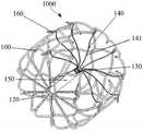
图2是本发明根据一实施例所提供的医疗器械的立体结构示意图;Fig. 2 is a schematic three-dimensional structure diagram of a medical device provided by the present invention according to an embodiment;
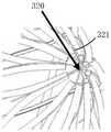
图3是本发明根据一实施例所提供的医疗器械释放且支架尾部未锚定时的结构示意图;Fig. 3 is a schematic structural view of the medical device provided according to an embodiment of the present invention when it is released and the tail of the stent is not anchored;
图4a是本发明根据一实施例所提供的采用2根丝形成两个夹持体的局部放大图;Fig. 4a is a partial enlarged view of two clamping bodies formed by using two wires according to an embodiment of the present invention;
图4b是本发明根据一实施例所提供的采用5根丝形成五个夹持体的局部放大图;Fig. 4b is a partial enlarged view of five clamping bodies formed by using five wires according to an embodiment of the present invention;
图4c是本发明根据一实施例所提供的采用10根丝形成十个夹持体的局部放大图;Fig. 4c is a partial enlarged view of ten clamping bodies formed by using 10 wires according to an embodiment of the present invention;
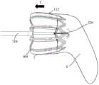
图5a是本发明根据一实施例所提供的医疗器械用于封堵左心耳并在左心耳内释放以后支架尾部未锚定时的状态示意图;Fig. 5a is a schematic diagram of the state when the tail of the stent is not anchored after the medical device provided by the present invention is used to occlude the left atrial appendage and released in the left atrial appendage;
图5b是本发明根据一实施例所提供的医疗器械用于封堵左心耳并在左心耳内释放以后且支架尾部已展开的状态示意图;Fig. 5b is a schematic diagram of a state in which the medical device provided by the present invention is used to occlude the left atrial appendage and released in the left atrial appendage according to an embodiment, and the tail of the stent has been deployed;
图5c是本发明根据一实施例所提供的在撤去输送器以及束缚装置后,支架在左心耳内定位固定的状态示意图;Fig. 5c is a schematic diagram of the position and fixation of the stent in the left atrial appendage after the conveyor and the restraint device are removed according to an embodiment of the present invention;
图6是本发明根据另一实施例提供的医疗器械的主视结构示意图。Fig. 6 is a schematic front view structural diagram of a medical device according to another embodiment of the present invention.
具体实施方式Detailed ways
为使本发明的目的、优点和特征更加清楚,以下结合附图对本发明的各种实施例作进一步详细说明。需说明的是,附图均采用非常简化的形式且均使用非精准的比例,仅用以方便、明晰地辅助说明本发明实施例的目的。In order to make the purpose, advantages and features of the present invention clearer, various embodiments of the present invention will be further described in detail below in conjunction with the accompanying drawings. It should be noted that all the drawings are in a very simplified form and use imprecise scales, and are only used to facilitate and clearly assist the purpose of illustrating the embodiments of the present invention.
如在本说明书中所使用的,单数形式“一”、“一个”以及“该”包括复数对象,除非内容另外明确指出外。如在本说明书中所使用的,“多个”的含义通常包括二个或二个以上,除非内容另外明确指出外。如在本说明书中所使用的,术语“或”通常是以包括“和/或”的含义而进行使用的,除非内容另外明确指出外。术语“近端”通常是指靠近医疗器械操作者的一端,“远端”是指远离医疗器械操作者的一端。附图中相同或相似的附图标记代表相同或相似的部件。As used in this specification, the singular forms "a", "an" and "the" include plural referents unless the content clearly dictates otherwise. As used in this specification, the meaning of "plurality" generally includes two or more, unless the content clearly states otherwise. As used in this specification, the term "or" is generally employed in its sense including "and/or" unless the content clearly dictates otherwise. The term "proximal" generally refers to the end near the operator of the medical device, and "distal" refers to the end away from the operator of the medical device. The same or similar reference numerals in the drawings represent the same or similar components.
本发明的核心思想是提供一种医疗器械,包括支架和束缚装置,所述束缚装置用于约束支架的尾部,以此避免支架在输送过程中产生过大的形变,同时也能避免支架在输送过程中尾部发生缠结,这些均有利于支架脱离鞘管后释放时顺利展开而确保成功释放,从而提高手术成功率。需补充说明的是,本发明的医疗器械可以应用于封堵左心耳,还可以用于其他腔体的封堵,例如是左心耳封堵器、血管封堵器等;或者是血管滤器、心脏瓣膜支架、覆膜支架等。The core idea of the present invention is to provide a medical device, including a stent and a restraint device, the restraint device is used to constrain the tail of the stent, so as to avoid excessive deformation of the stent during delivery, and at the same time prevent the stent from being deformed during delivery. Tangling occurs at the tail during the process, which is conducive to the smooth deployment of the stent when it is released from the sheath to ensure successful release, thereby improving the success rate of the operation. It should be added that the medical device of the present invention can be used to occlude the left atrial appendage, and can also be used to occlude other cavities, such as left atrial appendage occluders, blood vessel occluders, etc.; or vascular filters, heart Valve stents, stent grafts, etc.
更详细来说,本发的支架具有相对的第一近端和第一远端,所述第一远端被配置为具有展开状态和聚拢状态,所述第一远端的尾部包括若干凸起。而本发明提供的束缚装置包括主体和设置于所述主体之远端的夹持机构。实际使用时,所述主体经所述第一近端延伸至所述第一远端,且所述夹持机构穿过全部或部分凸起而限制凸起间的相对运动,由此防止支架的尾部在聚拢过程中发生缠结,同时还可避免输送及释放过程中相关部件(例如中空推送管与牵引机构)相对受力,从而还可减少支架在输送鞘管内的变形,进一步降低支架尾部缠结的风险。In more detail, the stent of the present invention has an opposite first proximal end and a first distal end, the first distal end is configured to have a deployed state and a gathered state, and the tail of the first distal end includes several protrusions . However, the binding device provided by the present invention includes a main body and a clamping mechanism disposed at the distal end of the main body. In actual use, the main body extends from the first proximal end to the first distal end, and the clamping mechanism passes through all or part of the protrusions to restrict the relative movement between the protrusions, thereby preventing the bracket from moving The tail is tangled during the gathering process, and at the same time, it can avoid relative stress on related components (such as the hollow push tube and traction mechanism) during the delivery and release process, thereby reducing the deformation of the stent in the delivery sheath and further reducing the entanglement of the stent tail. knot risk.
例如当本发明的医疗器械用于左心耳封堵时,其实际使用过程包括以下几个方面:For example, when the medical device of the present invention is used for left atrial appendage occlusion, its actual use process includes the following aspects:
输送过程:首先将支架(即封堵器)安装在输送鞘管内进行输送;此过程中,可先通过支架自带的牵引机构以及输送器中的驱动件将支架的尾部聚拢之后装入输送鞘管,然后,再装入束缚装置来约束支架的尾部。束缚装置介入之后,驱动件(例如中空牵引管或牵引体)无需再对牵引机构产生力的作用(也即牵引机构没有对支架产生力的作用,而仅依靠束缚装置约束支架的尾部),这样做,使驱动件无需与输送器中的中空推送管保持相对位置不变,从而可避免牵引机构和中空推送管相对受力,由此便于操作者对支架的形态进行控制,从而减少支架在输送鞘管内的形变,以此避免支架尾部发生缠结的问题。Delivery process: first install the stent (i.e. occluder) in the delivery sheath for delivery; during this process, the tail of the stent can be gathered first through the traction mechanism that comes with the stent and the drive in the delivery device, and then put into the delivery sheath The tube, then, is fitted with a restraint device to constrain the tail of the stent. After the restraint device intervenes, the driving member (such as the hollow traction tube or traction body) no longer needs to exert force on the traction mechanism (that is, the traction mechanism does not exert force on the bracket, but only relies on the restraint device to constrain the tail of the bracket), so Do, so that the driving part does not need to keep the relative position of the hollow push tube in the conveyor unchanged, so as to avoid the relative force on the traction mechanism and the hollow push tube, which is convenient for the operator to control the shape of the stent, thereby reducing the need for the stent to be transported. Deformation in the sheath to avoid tangling of the tail of the stent.
释放过程:当支架到达预定位置(如左心耳)后,借助于输送器中的中空推送管将支架推出输送鞘管并进入左心耳,此时,支架上的锚定结构由于尾部的束缚而不会刺入目标组织(如左心耳壁),从而便术者通过中空推送管对支架的位置进行调整。当支架的位置确认调整无误后,再释放锚定结构,使支架的锚定结构展开而进入目标组织实现支架的固定。其中在释放锚定结构时,术者只要轻拉束缚装置,即可以解脱束缚装置对支架的束缚,而使支架的尾部展开,实现锚定结构的释放。且支架尾部释放过程中,由于支架的尾部被束缚装置宽松且有序地束缚,故在输送鞘管内支架的尾部不会缠结而在释放时能够顺利展开。Release process: when the stent reaches the predetermined position (such as the left atrial appendage), the stent is pushed out of the delivery sheath and enters the left atrial appendage with the help of the hollow push tube in the conveyor. It will penetrate the target tissue (such as the wall of the left atrial appendage), so that the operator can adjust the position of the stent through the hollow push tube. After the position of the stent is confirmed to be adjusted correctly, the anchoring structure is released, so that the anchoring structure of the stent is expanded and enters the target tissue to realize the fixation of the stent. When releasing the anchoring structure, the operator only needs to lightly pull the restraining device to release the restraint of the restraining device on the stent, and expand the tail of the stent to realize the release of the anchoring structure. In addition, during the release process of the tail of the stent, since the tail of the stent is loosely and orderly restrained by the restraint device, the tail of the stent will not be entangled in the delivery sheath and can be smoothly deployed during release.
回收过程:锚定结构释放后,如果发现支架的位置不准确,还可通过牵引机构和驱动件半回收支架,以重新调整支架的位置。具体的,通过驱动件拉动牵引机构,使牵引机构带动支架的第一远端聚拢,使锚定结构抽离目标组织,实现支架的半回收。且借助于中空推送管重新调整好支架的位置后,再撤离驱动件使支架的尾部展开而使锚定结构再次刺入目标组织,实现支架的固定。在一种方案中,前述驱动件可以是中空牵引管,其与牵引机构通过远端固定件可拆卸地连接(例如螺纹连接),从而通过中空牵引管驱动牵引机构拉动支架的第一远端,使支架的第一远端从展开转变到聚拢。因此,通过中空牵引管可实现支架的一次或多次回收,使用方便。在另一种方案中,前述驱动件还可以是柔性牵引件,如牵引绳或牵引丝,优选医用导丝,从而通过牵引绳或牵引丝等对牵引机构进行控制,实现支架的回收,此方案中,一旦撤去牵引绳或牵引丝,则无法再次回收支架,故而仅能实现一次性回收。然而,本发明对驱动件的类型不作特别限定,只要能够实现支架的半回收即可。Recovery process: After the anchoring structure is released, if the position of the support is found to be inaccurate, the support can also be half-recovered through the traction mechanism and the driving part to readjust the position of the support. Specifically, the traction mechanism is pulled by the driving member, so that the traction mechanism drives the first distal end of the stent to gather, so that the anchoring structure is pulled away from the target tissue, and half recovery of the stent is realized. And after readjusting the position of the bracket with the help of the hollow push tube, the driving part is withdrawn to expand the tail of the bracket so that the anchoring structure penetrates into the target tissue again to realize the fixation of the bracket. In one solution, the aforementioned driving member may be a hollow traction tube, which is detachably connected (for example, threaded) to the traction mechanism through a distal fixing member, so as to drive the traction mechanism through the hollow traction tube to pull the first distal end of the stent, The first distal end of the stent is transitioned from deployed to gathered. Therefore, one or more recovery of the bracket can be realized through the hollow traction tube, which is convenient to use. In another solution, the above-mentioned driving member can also be a flexible traction member, such as a traction rope or a traction wire, preferably a medical guide wire, so as to control the traction mechanism through the traction rope or traction wire, etc., to realize the recovery of the stent. Among them, once the traction rope or traction wire is removed, the stent cannot be recovered again, so only one-time recovery can be realized. However, the present invention does not specifically limit the type of the driving member, as long as the half recovery of the bracket can be realized.
进一步的,本发明中的医疗器械还包括近端固定件,所述近端固定件设置于所述第一近端,用于使所述第一近端形成闭合设置。进一步的,所述医疗器械还包括远端固定件和牵引机构。所述牵引机构包括若干牵引体(包括但不限于绳、丝等只承受拉力的构件,还可以是能够承受压力和拉力的构件)。在所述牵引机构中,所有所述牵引体的第一端均连接至所述远端固定件,所有所述牵引体的第二端均连接至所述第一远端。并且所述远端固定件被配置为能够朝向所述近端固定件方向运动,从而通过牵引机构带动第一远端从展开状态转变为聚拢状态,实现支架的半回收。本发明对支架尾部上的凸起的形状不作限定,例如可以是锯齿形、波浪形、梯形等。Further, the medical device in the present invention further includes a proximal fixing member, the proximal fixing member is disposed on the first proximal end, and is used to make the first proximal end form a closed configuration. Further, the medical device also includes a distal fixing piece and a traction mechanism. The traction mechanism includes several traction bodies (including but not limited to ropes, wires and other components that can only withstand tension, and can also be components that can withstand pressure and tension). In the traction mechanism, the first ends of all the traction bodies are connected to the distal fixing member, and the second ends of all the traction bodies are connected to the first distal end. And the distal fixing part is configured to be able to move towards the direction of the proximal fixing part, so that the first distal end is driven by the traction mechanism to change from the expanded state to the gathered state, so as to realize half-recovery of the stent. The present invention does not limit the shape of the protrusion on the tail of the bracket, for example, it may be zigzag, wave, trapezoid and so on.
发明人发现,输送过程中,当所述支架的第一远端受力而聚拢时,所述尾部上的凸起会发生缠结,最终导致支架释放时尾部无法顺利展开。对此,发明人进一步发现,导致凸起发生缠结的根本原因是,这些凸起之间会产生相对运动而容易发生缠绕、交叉等问题。因此,当所述支架的第一远端受力从展开状态转变为聚拢状态时,通过束缚装置的夹持机构穿过全部或部分凸起,可以较好的限制凸起间的相对运动,由此较好地控制输送过程中支架的形变,并避免尾部发生缠结的问题。The inventors found that during delivery, when the first distal end of the stent is brought together under force, the protrusions on the tail will be tangled, and eventually the tail cannot be smoothly deployed when the stent is released. In this regard, the inventors further found that the root cause of the tangle of the protrusions is that the relative motion between these protrusions is likely to cause problems such as entanglement and crossing. Therefore, when the first distal end of the stent is forced to change from the expanded state to the gathered state, the clamping mechanism of the restraint device passes through all or part of the protrusions, so that the relative movement between the protrusions can be better restricted. This better controls the deformation of the stent during delivery and avoids the problem of tail entanglement.
本发明的医疗器械还包括输送器,用于与支架配套使用。所述输送器包括中空推送管以及驱动件。所述中空推送管的远端用于与所述支架的第一近端可拆卸地连接。所述驱动件用于穿过所述中空推送管并穿入支架后与支架的第一远端可拆卸地连接,以通过驱动件驱动支架的第一远端从展开状态转变为聚拢状态。优选实施例中,所述中空推送管的远端与前述近端固定件可拆卸地连接,所述驱动件依次穿过中空推送管、近端固定件与所述远端固定件可拆卸地连接,使驱动件驱动所述远端固定件朝向所述近端固定件的方向运动,所述远端固定件再通过牵引机构带动支架的第一远端向内聚拢。此外,所述束缚装置的主体经所述中空推送管、近端固定件以及远端固定件后伸出所述支架的第一远端,从而使所述夹持机构在第一远端的外部张开而束缚第一远端的尾部。为此,通过输送器中的中空推送管可实现支架的输送、释放和位置调整,而通过输送器中的驱动件可实现支架的装载和半回收,但如前所述,这里的驱动件可以是中空牵引管或柔性牵引件。The medical device of the present invention also includes a delivery device for use with the stent. The conveyor includes a hollow push tube and a drive. The distal end of the hollow push tube is used for detachable connection with the first proximal end of the bracket. The driving member is used to pass through the hollow push tube and penetrate the stent and then be detachably connected with the first distal end of the stent, so that the first distal end of the stent can be driven to change from the expanded state to the gathered state through the driving member. In a preferred embodiment, the distal end of the hollow push tube is detachably connected to the aforementioned proximal fixing member, the driving member sequentially passes through the hollow pushing tube, and the proximal fixing member is detachably connected to the distal fixing member , so that the driving part drives the distal fixing part to move towards the direction of the proximal fixing part, and the distal fixing part drives the first distal end of the bracket to gather inward through the traction mechanism. In addition, the main body of the binding device protrudes from the first distal end of the bracket after passing through the hollow push tube, the proximal fixing part and the distal fixing part, so that the clamping mechanism is outside the first distal end. Open and restrain the first distal tail. For this reason, the delivery, release and position adjustment of the stent can be realized through the hollow push tube in the conveyor, and the loading and semi-recovery of the stent can be realized through the drive in the conveyor, but as mentioned earlier, the drive here can be It is a hollow traction tube or a flexible traction piece.
以下结合附图进一步详细说明本发明的医疗器械,且以下描述中,以封堵左心耳作为示例,但不应以此作为对本发明的限定。The medical device of the present invention will be further described in detail below in conjunction with the accompanying drawings, and in the following description, occlusion of the left atrial appendage is taken as an example, but this should not be used as a limitation of the present invention.
图1是本发明一实施例提供的医疗器械的主视结构示意图,图2是本发明一实施例所提供的医疗器械的立体结构示意图,图3是本发明一实施例提供的医疗器械释放后且支架尾部未锚定时的状态。如图1和图2所示,本发明实施例提供一种医疗器械1000,其包括支架100、输送器200和束缚装置300。Figure 1 is a schematic front view of a medical device provided by an embodiment of the present invention, Figure 2 is a schematic diagram of a three-dimensional structure of a medical device provided by an embodiment of the present invention, and Figure 3 is a schematic view of the medical device provided by an embodiment of the present invention after release And the state when the tail of the stent is not anchored. As shown in FIGS. 1 and 2 , an embodiment of the present invention provides a
参考图2,所述支架100具有相对的第一近端和第一远端,所述第一近端形成闭合设置,所述第一远端为敞开设置。其中,所述第一远端的尾部包括若干凸起111,本发明对凸起111的形状没有限制,包括但不限于为锯齿形。进一步的,所述支架100还包括近端固定件120,所述第一近端与近端固定件120相连接,用于使所述第一近端形成闭合设置。更进一步的,所述支架100还包括远端固定件130和牵引机构140。所述牵引机构140包括若干牵引体141,牵引体141的具体数量不作限定,只要能够拉动第一远端而使第一远端呈现聚拢状态即可。具体的,牵引体141的数量可以小于、等于或大于凸起111的数量,优选的,牵引体141的数量与凸起111的数量相一致。并且所有所述牵引体141的第一端均连接至所述远端固定件130,所有所述牵引体141的第二端均连接至所述第一远端。Referring to FIG. 2 , the
参考图1,所述输送器200包括中空推送管210以及中空牵引管220。实际应用时,所述中空推送管210的远端与支架100的第一近端可拆卸地连接,优选与所述近端固定件120可拆卸地连接,具体的连接方式不作限定。可选的,所述中空推送管210的远端与近端固定件120螺纹连接。而所述中空牵引管220即充当本发明的驱动件,其穿过中空推送管210并穿入支架100后与支架100的第一远端可拆卸地连接,优选的,中空牵引管220依次穿过中空推送管210、近端固定件120后与远端固定件130可拆卸地连接,可拆卸连接方式也不作限定。可选的,所述中空牵引管220的远端与远端固定件130螺纹连接。优选的,所述支架100还包括中空导向件150,所述中空导向件150的近端与所述支架100的第一近端固定连接,可选的,所述中空导向件150的近端与近端固定件120固定连接并与近端固定件120同轴布置,以允许所述远端固定件130以及至少部分所述牵引机构140从中空导向件150的远端穿入中空导向件150,从而方便控制支架100的形变姿态和方向,以方便回收。进一步地,所述中空牵引管220穿过近端固定件120后,进一步穿入中空导向件150,而后与远端固定件130可拆卸地连接。由此,通过拉动中空牵引管220的近端,便可驱动所述远端固定件130朝向所述近端固定件120的方向运动,所述远端固定件130再通过牵引机构140拉动支架100的第一远端向内聚拢,聚拢过程中,所有凸起111相互靠近甚至于相互抵靠在一起。Referring to FIG. 1 , the
所述束缚装置300的主体310穿过中空推送管210和支架100并进一步伸出支架100的第一远端,更具体的,所述主体310依次穿过中空推送管210、近端固定件120、中空导向件150以及远端固定件130后伸出所述支架100的第一远端,而使主体310之远端处的夹持机构320位于第一远端的外部,由此,通过夹持机构320穿过支架100之尾部上的全部或部分凸起111,可以限制凸起111间的相对运动,并还可以约束支架的尾部。The
具体的,所述束缚装置300包括主体310以及设置于所述主体310之远端的夹持机构320。在一实施例中,所述夹持机构320为多个夹持体321,如2个、3个、4个、5个或更多个。参考图图2和3,所述夹持机构320包括多个夹持体321,这些夹持体321穿过部分或全部凸起111,从而夹持住第一远端已经聚拢的支架的尾部,使得第一远端上的所有凸起111不能产生相对运动,从而避免凸起之间发生缠结的问题。这样做,在输送鞘管内,束缚装置与中空推送管之间不会产生相对位移,从而便于操作者对支架的形态进行控制,便于输送和回收。更具体的,装载支架100时,可先通过中空牵引管220稍微收拢支架100的第一远端,而后再将第一远端收拢的支架100装入输送鞘管,之后,再将束缚装置300穿入支架100,当夹持机构320在支架100的第一远端的外部通过自身结构形成夹持状态后,即可牢固约束支架的尾部,使支架的尾部保持在聚拢状态,此时,操作者无需再对中空牵引管220施加作用力,使中空牵引管220可以相对于中空推送管210活动,从而减少支架在输送鞘管内的形变,例如图3所示,支架的形变姿态和方向得到了较好的控制。后续再通过中空推送管210将支架100推出输送鞘管后,依然可通过束缚装置300约束支架尾部,直到支架100的位置调整无误后,即可向近端拉动束缚装置300的主体310,使得夹持机构320受力打开或形变而解脱对支架尾部的约束,由于支架的尾部具有弹性,在弹性力作用下,支架的尾部自动展开,使支架上的锚定结构112朝向左心耳壁,并进一步刺入左心耳壁。Specifically, the
结合图5a至图5c更详细来说。首先如图5a所示,当支架100被推出输送鞘管之后且未解脱束缚装置300时,支架100进入到左心耳S,此时,可通过中空推送管210对支架100的位置进行调整,例如沿箭头A所指示的方向前后移动支架100,或者沿箭头B所指示的方向旋转支架100,直至支架100的位置符合要求。接下去如图5b所示,待操作者调整好支架100的位置后,操作者可以轻轻拉扯束缚装置300便可释放夹持机构320,从而释放支架100的尾部,进而将锚定结构112刺入左心耳壁,此后,沿箭头C所指示的方向回撤束缚装置300即可。最后如图5c所示,支架100成功释放后,操作者只需要将束缚装置300、中空推送管210以及中空牵引管220相继撤离人体,即可完成左心耳的封堵。It will be described in more detail in conjunction with FIGS. 5a to 5c. First, as shown in FIG. 5a, when the
进一步地,所述夹持体321优选为丝状构件,丝状构件需具有足够的强度和良好的变形能力,从而可实现牢固的夹持,并方便通过弹性形变顺利解脱。更进一步地,所述夹持体321由弹性材料或形状记忆材料制成,以赋予夹持机构320优良的形变性能和足够的力学性能,例如所述夹持体321的材料可选自镍钛合金或不锈钢。更优选的,所述夹持体321为镍钛丝,镍钛丝可选为圆形丝,圆形丝的直径可选为0.15mm,以赋予镍钛丝足够大的刚度和良好的形变性能,并还能减小输送尺寸。Further, the clamping
进一步,本发明对夹持体321的具体数量不作限定,具体根据支架尾部的尺寸进行设定。接下去以支架100之尾部上的10个凸起111作为示意,对夹持体321的夹持方式作进一步的说明。Further, the present invention does not limit the specific number of clamping
针对图3中虚线框圈示区域的局部放大结构进行说明。如图4a所示,所述夹持机构320可包括两根丝,每根丝呈“C”字型,且将两根丝交叉布置,即可获得两个夹持体321,每个夹持体321也呈“C”字型,使每个夹持体321自带两个卡爪,并在部分凸起111内穿设卡爪,从而通过四个卡爪夹紧一部分凸起111,且由于支架的10个凸起之间存在相互作用力,使得所有凸起都能够被束缚住而不会产生相对运动。或者,如图4b所示,所述夹持机构320也可包括五根丝,每根丝的一端弯折形成一个夹持体321,进而将五根丝沿周向间隔布置,便可获得五个夹持体321,每个夹持体321构成一个卡爪,且也在部分凸起111内穿设卡爪,从而通过五个卡爪夹紧一部分凸起111,这样做,也能使所有凸起被有效地束缚而不会产生相对运动。又或者,如图4c所示,所述夹持机构320可包括十根丝,与图4b类似,每根丝的一端弯折形成一个夹持体321,进而将十根丝沿周向间隔布置,便可获得十个夹持体321,同样的,每个夹持体321也构成一个卡爪,所不同的,在每个凸起111内穿设一个卡爪,从而通过十个卡爪夹紧所有凸起111。The partial enlarged structure of the area circled by the dotted line in FIG. 3 will be described. As shown in Figure 4a, the
在其他实施例中,所述夹持体321也可以呈“V”字型,使一个夹持体321自带两个卡爪,此时,所述夹持机构320可以为单个夹持体321,例如夹持体321呈“C字”型或“V”字型,通过将夹持体321的两个卡爪分别穿入不同的凸起111中,可对部分凸起111实现夹紧。在替代性实施例中,所述夹持机构320为多个夹持体321,此时,夹持体321既可自带一个卡爪,也可自带两个卡爪,且可组合使用。如果夹持体321自带一个卡爪,夹持体321的一端设置在支架100的外部,另一端穿入凸起111之中,且各个夹持体321穿设于不同的凸起中。In other embodiments, the clamping
在本发明的束缚装置300中,通过夹持体321穿过全部或部分凸起111来限制凸起111间的相对运动,这样做的好处是,可以宽松且有序地束缚各个凸起,更方便支架尾部展开。本实施例中,每个凸起111为镂空结构,也即具有网孔,每个夹持体321的一端经由凸起的网孔穿入支架100。In the
补充说明的是,当所述夹持机构320为单个夹持体时,每个夹持体自带两个卡爪,卡爪的数量小于凸起的数量。而当所述夹持机构320为多个夹持体321时,每个夹持体321自带一个卡爪,卡爪的数量小于或等于凸起的数量,也即夹持体的数量小于或等于凸起的数量。It is added that when the
以多个夹持体321进行说明。例如所述夹持体321的数量与凸起111的数量相同,从而可以在每个凸起111内穿设一个夹持体321,如图4c所示。又例如,所述夹持体321的数量小于凸起111的数量,优选的,所述凸起111的数量为所述夹持体321的2倍,例如10个凸起111配置5个夹持体321,以减小夹持机构320的尺寸,从而减小输送尺寸,更优选的,每间隔1个或更多个凸起后在相应凸起内穿设一个夹持体321。或者,在10个凸起111的情况下,所述夹持体321为五个,从而每间隔1个凸起后在相邻的凸起内穿设一个夹持体321,这样做可以兼顾输送尺寸和夹持效果。此外,随着夹持体321的增多,夹持体321的直径也应该更小。例如当夹持体321为四个或五个时,可采用直径为0.15mm的圆形镍钛丝,又例如夹持体321为十个时,可采用直径为0.04mm的镍钛丝。A plurality of clamping
图6是束缚装置300的另一种实施方式,其中夹持机构320为单个夹持体321’,夹持体321’可以依次穿过每一个凸起,也可以间隔穿过部分凸起。以8个凸起为例,夹持体321’按顺时针穿过第1、2、3、5、6、7个凸起,余下第4、8个凸起未被夹持。进一步的,所述夹持体321’整体呈“C”字型,但对C字型的开口大小不作限定,只要能够有效收紧所有凸起即可。所述夹持体321优选为弹性丝,例如镍钛丝或者其他以镍为基材组成的合金。操作时,只要轻轻拉动或旋转主体310即可将夹持体321’抽离,实现支架尾部的释放,结构简单,操作方便。Fig. 6 is another embodiment of the
本发明对束缚装置300的制备方式不作限定,可以有多种制备方式。例如主体310被构造成一根直杆,在直杆的远端通过焊接或其他方式连接数根丝(如图4a至图4c所示的丝)而形成夹持机构320。又或者,数根丝在一端被处理成弯曲的形状,并可通过套管将这些丝束缚在一起,例如套管构造为主体310。再或者,主体310为一根较粗的管子和丝,通过在丝或管子的一端切割或其他方式分叉形成数根细丝,然后这些细丝再处理成弯曲形状以形成夹持机构320。The present invention does not limit the preparation method of the
进一步,当夹持体321相对于主体3210弯曲时,每个夹持体321相对于主体310的弯曲角度优选在30°~180°之间,更优选为53°至72°。发明人通过实验发现,当夹持体321位于该弯曲角度区间时,可以同时满足有效固定和方便解脱。本文中,取主体310的近端指向远端方向为主体310的轴线的正方向,则夹持体321相对于主体310的轴线的正方向的夹角为所述弯曲角度。Further, when the clamping
进一步,所述支架100还包括生物相容性膜,所述生物相容性覆盖于支架100的外表面,且不覆盖所述凸起。Further, the
需知的,夹持体还可以有其他结构形式,本申请对此均适用;此外,支架可以是编织支架或切割支架,本发明对此不作限定。It should be known that the clamping body may also have other structural forms, and this application is applicable to all of them; in addition, the stent may be a braided stent or a cut stent, which is not limited in the present invention.
综上,根据本发明实施例提供的技术方案,在实际使用过程中,通过本发明提供的束缚装置能够较好地束缚支架的尾部,使得支架在输送鞘管内的形变可控而方便输送和打开,而且支架的尾部也不会发生缠结,较好的保证了支架出鞘后释放的成功率。同时,本发明的支架出鞘时其锚定结构不会在第一时间内锚定在左心耳内壁上,能够避免操作者由于操作失误,对患者左心耳壁造成的伤害,并且还可以降低手术中心包积液的风险。In summary, according to the technical solution provided by the embodiment of the present invention, in actual use, the restraint device provided by the present invention can better bind the tail of the stent, so that the deformation of the stent in the delivery sheath is controllable and convenient for delivery and opening , and the tail of the stent will not be tangled, which better guarantees the success rate of the release of the stent after it is unsheathed. At the same time, when the stent of the present invention is out of the sheath, its anchoring structure will not be anchored on the inner wall of the left atrial appendage in the first time, which can prevent the operator from causing damage to the patient's left atrial appendage wall due to operational errors, and can also reduce the risk of surgery. Risk of pericardial effusion.
上述描述仅是对本发明较佳实施例的描述,并非对本发明范围的任何限定,本发明领域的普通技术人员根据上述揭示内容做的任何变更、修饰,均属于权利要求书的保护范围。The above description is only a description of the preferred embodiments of the present invention, and does not limit the scope of the present invention. Any changes and modifications made by those of ordinary skill in the field of the present invention based on the above disclosures shall fall within the protection scope of the claims.
Claims (13)
Priority Applications (4)
| Application Number | Priority Date | Filing Date | Title |
|---|---|---|---|
| CN201911032196.1ACN112716554B (en) | 2019-10-28 | 2019-10-28 | Medical instrument |
| US17/772,320US12239324B2 (en) | 2019-10-28 | 2020-10-20 | Medical instrument |
| EP20882016.7AEP4035608B1 (en) | 2019-10-28 | 2020-10-20 | Medical instrument |
| PCT/CN2020/122019WO2021082974A1 (en) | 2019-10-28 | 2020-10-20 | Medical instrument |
Applications Claiming Priority (1)
| Application Number | Priority Date | Filing Date | Title |
|---|---|---|---|
| CN201911032196.1ACN112716554B (en) | 2019-10-28 | 2019-10-28 | Medical instrument |
Publications (2)
| Publication Number | Publication Date |
|---|---|
| CN112716554A CN112716554A (en) | 2021-04-30 |
| CN112716554Btrue CN112716554B (en) | 2023-03-24 |
Family
ID=75588854
Family Applications (1)
| Application Number | Title | Priority Date | Filing Date |
|---|---|---|---|
| CN201911032196.1AActiveCN112716554B (en) | 2019-10-28 | 2019-10-28 | Medical instrument |
Country Status (4)
| Country | Link |
|---|---|
| US (1) | US12239324B2 (en) |
| EP (1) | EP4035608B1 (en) |
| CN (1) | CN112716554B (en) |
| WO (1) | WO2021082974A1 (en) |
Families Citing this family (8)
| Publication number | Priority date | Publication date | Assignee | Title |
|---|---|---|---|---|
| JP6423851B2 (en) | 2013-03-13 | 2018-11-14 | アーロン・ヴィ・カプラン | Device for emptying the left atrial appendage |
| US11399842B2 (en) | 2013-03-13 | 2022-08-02 | Conformal Medical, Inc. | Devices and methods for excluding the left atrial appendage |
| WO2018081466A2 (en) | 2016-10-27 | 2018-05-03 | Conformal Medical, Inc. | Devices and methods for excluding the left atrial appendage |
| US11426172B2 (en) | 2016-10-27 | 2022-08-30 | Conformal Medical, Inc. | Devices and methods for excluding the left atrial appendage |
| US12144508B2 (en) | 2019-02-08 | 2024-11-19 | Conformal Medical, Inc. | Devices and methods for excluding the left atrial appendage |
| US12268394B2 (en) | 2019-02-08 | 2025-04-08 | Conformal Medical, Inc. | Devices and methods for excluding the left atrial appendage |
| CN114041896B (en)* | 2021-12-21 | 2024-05-07 | 启晨(上海)医疗器械有限公司 | Airway obstruction device |
| CN116492106A (en)* | 2023-03-16 | 2023-07-28 | 先健科技(深圳)有限公司 | A medical device operating device and system thereof |
Family Cites Families (13)
| Publication number | Priority date | Publication date | Assignee | Title |
|---|---|---|---|---|
| US7758626B2 (en)* | 2004-07-20 | 2010-07-20 | Medtronic Vascular, Inc. | Device and method for delivering an endovascular stent-graft having a longitudinally unsupported portion |
| EP1988851A2 (en) | 2006-02-14 | 2008-11-12 | Sadra Medical, Inc. | Systems and methods for delivering a medical implant |
| US8764772B2 (en)* | 2008-02-21 | 2014-07-01 | Cook Medical Technologies Llc | Occlusion device |
| EP2349124B1 (en)* | 2008-09-05 | 2018-10-17 | Cook Medical Technologies LLC | Apparatus for improved stent deployment |
| EP3238661B1 (en)* | 2008-10-10 | 2019-05-22 | Boston Scientific Scimed, Inc. | Medical devices and delivery systems for delivering medical devices |
| US10064628B2 (en) | 2009-06-17 | 2018-09-04 | Coherex Medical, Inc. | Medical device for modification of left atrial appendage and related systems and methods |
| US20110054515A1 (en)* | 2009-08-25 | 2011-03-03 | John Bridgeman | Device and method for occluding the left atrial appendage |
| US9561102B2 (en)* | 2010-06-02 | 2017-02-07 | Medtronic, Inc. | Transcatheter delivery system and method with controlled expansion and contraction of prosthetic heart valve |
| WO2015075708A1 (en)* | 2013-11-19 | 2015-05-28 | Endospan Ltd. | Stent system with radial-expansion locking |
| EP3174502B1 (en)* | 2014-07-30 | 2022-04-06 | Cardiovalve Ltd | Apparatus for implantation of an articulatable prosthetic valve |
| CN104688292B (en)* | 2015-02-15 | 2017-08-25 | 上海形状记忆合金材料有限公司 | A kind of left atrial appendage occlusion device and plugging system |
| EP3294220B1 (en) | 2015-05-14 | 2023-12-06 | Cephea Valve Technologies, Inc. | Cardiac valve delivery devices and systems |
| CN108236479A (en) | 2016-12-26 | 2018-07-03 | 上海微创医疗器械(集团)有限公司 | Left atrial appendage occlusion system, occluder for left auricle and its conveyer |
- 2019
- 2019-10-28CNCN201911032196.1Apatent/CN112716554B/enactiveActive
- 2020
- 2020-10-20WOPCT/CN2020/122019patent/WO2021082974A1/ennot_activeCeased
- 2020-10-20EPEP20882016.7Apatent/EP4035608B1/enactiveActive
- 2020-10-20USUS17/772,320patent/US12239324B2/enactiveActive
Also Published As
| Publication number | Publication date |
|---|---|
| US20220401112A1 (en) | 2022-12-22 |
| EP4035608B1 (en) | 2025-03-12 |
| CN112716554A (en) | 2021-04-30 |
| US12239324B2 (en) | 2025-03-04 |
| WO2021082974A1 (en) | 2021-05-06 |
| EP4035608A1 (en) | 2022-08-03 |
| EP4035608A4 (en) | 2022-11-23 |
| EP4035608C0 (en) | 2025-03-12 |
Similar Documents
| Publication | Publication Date | Title |
|---|---|---|
| CN112716554B (en) | Medical instrument | |
| US11207073B2 (en) | Tissue ligation devices and methods therefor | |
| US11266389B2 (en) | Body part repositioning apparatus and method | |
| US6936058B2 (en) | Over-the-wire interlock attachment/detachment mechanism | |
| US20160278782A1 (en) | Embolic coil delivery system with easy-release knot | |
| CN110960279A (en) | Left auricle plugging device and left auricle plugging system | |
| US11871932B2 (en) | Occlusion device | |
| JP2007535997A (en) | Capturing mechanism of tubular septal occluder | |
| CN110522486A (en) | Closure stent for left atrial appendage |
Legal Events
| Date | Code | Title | Description |
|---|---|---|---|
| PB01 | Publication | ||
| PB01 | Publication | ||
| SE01 | Entry into force of request for substantive examination | ||
| SE01 | Entry into force of request for substantive examination | ||
| GR01 | Patent grant | ||
| GR01 | Patent grant |