Movatterモバイル変換


[0]ホーム

URL:


CN112710914B - Fault diagnosis method of intelligent substation considering control center fault information tampering - Google Patents

Fault diagnosis method of intelligent substation considering control center fault information tampering
Download PDF

Info

Publication number
CN112710914B
CN112710914BCN202011485183.2ACN202011485183ACN112710914BCN 112710914 BCN112710914 BCN 112710914BCN 202011485183 ACN202011485183 ACN 202011485183ACN 112710914 BCN112710914 BCN 112710914B
Authority
CN
China
Prior art keywords
neuron
fault
value
inference
temporal
Prior art date
Legal status (The legal status is an assumption and is not a legal conclusion. Google has not performed a legal analysis and makes no representation as to the accuracy of the status listed.)
Active
Application number
CN202011485183.2A
Other languages
Chinese (zh)
Other versions
CN112710914A (en
Inventor
王涛
程亮
刘伟
黄著
陈孝天
周科全
刘力源
古世甫
詹红霞
张彼德
Current Assignee (The listed assignees may be inaccurate. Google has not performed a legal analysis and makes no representation or warranty as to the accuracy of the list.)
Wu Yuxin
Original Assignee
Xihua University
Priority date (The priority date is an assumption and is not a legal conclusion. Google has not performed a legal analysis and makes no representation as to the accuracy of the date listed.)
Filing date
Publication date
Application filed by Xihua UniversityfiledCriticalXihua University
Priority to CN202011485183.2ApriorityCriticalpatent/CN112710914B/en
Publication of CN112710914ApublicationCriticalpatent/CN112710914A/en
Application grantedgrantedCritical
Publication of CN112710914BpublicationCriticalpatent/CN112710914B/en
Activelegal-statusCriticalCurrent
Anticipated expirationlegal-statusCritical

Links

Images

Classifications

Landscapes

Abstract

The invention discloses an intelligent substation fault diagnosis method considering control center fault information tampering, which comprises the steps of firstly finding suspected fault elements by adopting a fuzzy C-means clustering algorithm, then evaluating the telemetering measurement uncertainty degree of each suspected fault element by calculating the voltage sampling value clustering coefficient of each suspected fault element, further determining input data of a fault element identification model, finally providing a fault element identification model based on a multi-element pulse neural membrane system and a multi-element pulse matrix reasoning algorithm corresponding to the fault element identification model, and solving to obtain a fault diagnosis result of the suspected fault elements. The method and the system can effectively solve the problem of intelligent substation fault diagnosis under the condition that the fault information of the control center is tampered, and can also solve the problem of high uncertainty and inaccuracy of the fault information caused by the fact that the fault information is tampered, which cannot be processed by the existing method.

Description

Translated fromChinese
计及控制中心故障信息篡改的智能变电站故障诊断方法Fault diagnosis method of intelligent substation considering control center fault information tampering

技术领域technical field

本发明属于智能变电站安全技术领域,具体涉及一种计及控制中心故障信息篡改的智能变电站故障诊断方法的设计。The invention belongs to the technical field of intelligent substation security, and in particular relates to the design of a fault diagnosis method for an intelligent substation which takes into account the tampering of fault information of a control center.

背景技术Background technique

智能变电站担负着电能传输与变换的重任,是智能电网与能源互联网的重要枢纽。随着智能电网和能源互联网的大力发展,智能变电站的故障诊断功能,对于故障发生后快速供能具有重要作用。变电站故障诊断是指当其发生故障时,通过控制中心获得的故障告警信息(包括变电站一次系统和二次系统告警信息),采用诊断方法确定故障元件,并评价相关保护或断路器的不正常动作。目前,变电站的故障诊断方法主要集中于变电站常规故障的诊断工作,所采用的方法主要有专家系统、模糊集理论、Petri网、贝叶斯网络和人工神经网络等;而对于信息袭击等极端情况下的非常规故障诊断的研究工作,还远远不够。The smart substation is responsible for the transmission and transformation of electric energy, and is an important hub of the smart grid and the energy Internet. With the vigorous development of smart grid and energy Internet, the fault diagnosis function of smart substation plays an important role in rapid energy supply after a fault occurs. Substation fault diagnosis refers to the fault alarm information (including the substation primary system and secondary system alarm information) obtained through the control center when a fault occurs, the diagnosis method is used to determine the faulty components, and the abnormal operation of the relevant protection or circuit breaker is evaluated. . At present, the fault diagnosis methods of substations mainly focus on the diagnosis of conventional faults in substations. The methods used mainly include expert systems, fuzzy set theory, Petri nets, Bayesian networks and artificial neural networks. For extreme cases such as information attacks The research work on unconventional fault diagnosis is far from enough.

随着智能变电站的快速发展,通信网与物理网的相依性越发增强,其故障诊断过程中的问题也逐渐凸显出来:(1)当远动信息或者站内电子式互感器遇到较大干扰时,会导致故障信息畸变或丢失;(2)变电站之间的对时不准导致故障信息存在时标偏差;(3)通信系统与物理系统的强烈相依性使智能变电站相较于常规电站更易遭受黑客攻击。此外,随着信息物理社会系统的全息感知、人机交互和数据高效共享的逐渐实现,将导致智能变电站更易遭受数据篡改等信息袭击。With the rapid development of smart substations, the interdependence between the communication network and the physical network has become stronger and stronger, and the problems in the fault diagnosis process have gradually become prominent: (1) When the telecontrol information or the electronic transformer in the station encounters great interference , which will cause the fault information to be distorted or lost; (2) the inaccurate timing between substations leads to the time scale deviation of the fault information; (3) the strong interdependence between the communication system and the physical system makes the smart substation more vulnerable than the conventional power station. hacker attack. In addition, with the gradual realization of holographic perception, human-computer interaction and efficient data sharing of cyber-physical social systems, smart substations will be more vulnerable to information attacks such as data tampering.

例如,黑客通过篡改控制中心的数据采集与监视控制(Supervisory Control AndData Acquisition,SCADA)和故障录波系统的故障信息,即故障遥信量和故障遥测量,人为地大大增强了故障信息的不确定性和不精确性,致使现有故障诊断方法不能快速准确地识别真实故障元件,不能快速恢复故障后供电,进而造成重大经济损失。由于现有研究和诊断系统并未考虑上述极端情况,因此相关诊断方法亟待探索。For example, by tampering with the data acquisition and monitoring control (Supervisory Control And Data Acquisition, SCADA) of the control center and the fault information of the fault recording system, that is, the fault remote signal quantity and fault remote measurement, the uncertainty of the fault information is artificially greatly enhanced. The existing fault diagnosis methods cannot quickly and accurately identify the real faulty components, and cannot quickly restore the power supply after the fault, thereby causing significant economic losses. Since existing research and diagnostic systems do not consider the above extreme cases, relevant diagnostic methods need to be explored urgently.

发明内容SUMMARY OF THE INVENTION

本发明的目的是为了解决智能变电站诊断方法存在的上述问题,提出了一种计及控制中心故障信息篡改的智能变电站故障诊断方法,以应对由于黑客信息袭击所引起的故障信息中高度不确定性和不精确性的问题。The purpose of the present invention is to solve the above problems existing in the intelligent substation diagnosis method, and propose a intelligent substation fault diagnosis method which takes into account the tampering of the control center fault information, so as to deal with the high uncertainty in the fault information caused by the hacker information attack. and imprecision.

本发明的技术方案为:计及控制中心故障信息篡改的智能变电站故障诊断方法,包括以下步骤:The technical scheme of the present invention is: a fault diagnosis method for an intelligent substation considering the tampering of the fault information of the control center, comprising the following steps:

S1、采用模糊C均值聚类算法对智能变电站遥测量的归一化电压值进行聚类分析,并根据聚类结果确定疑似故障元件。S1. Use the fuzzy C-means clustering algorithm to perform cluster analysis on the normalized voltage values of the remote measurement of the smart substation, and determine the suspected faulty components according to the clustering results.

S2、针对各疑似故障元件,采用幅值序列点约束和时间序列点约束计算得到序列点隶属矩阵D,并根据序列点隶属矩阵D计算得到各疑似故障元件的电压采样值合群系数,并根据电压采样值合群系数确定故障元件识别模型的输入数据。S2. For each suspected fault element, the sequence point membership matrix D is obtained by calculating the amplitude sequence point constraint and the time series point constraint, and the voltage sampling value group coefficient of each suspected fault element is calculated according to the sequence point membership matrix D, and according to the voltage The sampled value clustering coefficient determines the input data for the faulty component identification model.

S3、根据智能变电站的物理拓扑结构、保护装置配置和故障告警信息,为每一个疑似故障元件建立基于多元脉冲神经膜系统的故障元件识别模型,并通过计算时序约束隶属度来修正各个故障元件识别模型中保护装置对应输入神经元的初始脉冲值。S3. According to the physical topology of the smart substation, the configuration of the protection device and the fault alarm information, a fault element identification model based on the multi-pulse neural membrane system is established for each suspected fault element, and the identification of each fault element is corrected by calculating the timing constraint membership degree. The protection device in the model corresponds to the initial pulse value of the input neuron.

S4、通过多元脉冲矩阵推理算法求解基于多元脉冲神经膜系统的故障元件识别模型,得到疑似故障元件的故障诊断结果。S4, solving the fault component identification model based on the multi-pulse neural membrane system through the multi-pulse matrix inference algorithm, and obtaining the fault diagnosis result of the suspected fault component.

进一步地,步骤S1包括以下分步骤:Further, step S1 includes the following sub-steps:

S11、对智能变电站正常运行状态下的历史电压数据和未遭受攻击但故障状态下的历史电压数据进行处理,得到清洁数据,并提取智能变电站各母线和变压器的实时电压采样值。S11. Process the historical voltage data in the normal operation state of the smart substation and the historical voltage data in the unattacked but faulty state to obtain clean data, and extract real-time voltage sampling values of each busbar and transformer of the smart substation.

S12、当检测到智能变电站故障发生时,确定故障时间窗,并对智能变电站遥测量中的实时电压采样值进行归一化处理,得到归一化电压值。S12, when it is detected that a fault occurs in the smart substation, determine the fault time window, and normalize the real-time voltage sampling value in the remote measurement of the smart substation to obtain a normalized voltage value.

S13、将归一化电压值作为模糊C均值聚类算法的输入进行数据聚类,根据聚类结果,将与聚类中心的距离大于距离阈值的母线或变压器以及与它们相连的馈线作为疑似故障元件。S13. Use the normalized voltage value as the input of the fuzzy C-means clustering algorithm to perform data clustering, and according to the clustering result, take the bus or transformer whose distance from the cluster center is greater than the distance threshold and the feeder connected to them as the suspected fault element.

进一步地,步骤S12中对智能变电站遥测量中的电压进行归一化处理的方法具体为:Further, the method for normalizing the voltage in the remote measurement of the smart substation in step S12 is specifically:

采用以下公式对智能变电站遥测量中的电压进行归一化处理,并提取0s、0.01s、0.03s和0.05s四个时刻的归一化电压值:Use the following formula to normalize the voltage in the remote measurement of the smart substation, and extract the normalized voltage values at four times of 0s, 0.01s, 0.03s and 0.05s:

Figure BDA0002839151940000021

其中U'为归一化电压值,U为待归一化的实时电压采样值,Umax和Umin分别为清洁数据中历史电压值的最大值和最小值。Wherein U' is the normalized voltage value, U is the real-time voltage sampling value to be normalized, and Umax and Umin are the maximum and minimum values of the historical voltage values in the cleaning data, respectively.

进一步地,步骤S2包括以下分步骤:Further, step S2 includes the following sub-steps:

S21、针对各疑似故障元件,采用幅值序列点约束

Figure BDA0002839151940000022
和时间序列点约束
Figure BDA0002839151940000023
计算得到序列点隶属矩阵D。S21. For each suspected faulty component, use the amplitude sequence point constraint
Figure BDA0002839151940000022
and time series point constraints
Figure BDA0002839151940000023
The sequence point membership matrix D is obtained by calculation.

S22、根据序列点隶属矩阵D计算得到各疑似故障元件的电压采样值合群系数p。S22 , calculating the grouping coefficient p of the voltage sampling values of each suspected faulty element according to the sequence point membership matrix D.

S23、判断各疑似故障元件的电压采样值合群系数p是否大于设定阈值,若是则将该疑似故障元件的电压采样值合群系数p、遥信量信息和时序信息作为故障元件识别模型的输入数据,否则将该疑似故障元件的遥信量信息和时序信息作为故障元件识别模型的输入数据。S23. Determine whether the grouping coefficient p of the voltage sampling values of each suspected faulty element is greater than the set threshold, and if so, take the grouping coefficient p, the remote signal quantity information and the timing information of the voltage sampling value of the suspected faulty element as the input data of the fault element identification model , otherwise the remote signal quantity information and timing information of the suspected faulty element are used as the input data of the faulty element identification model.

进一步地,步骤S21中序列点隶属矩阵D表示为:Further, the sequence point membership matrix D in step S21 is expressed as:

Figure BDA0002839151940000031

其中,

Figure BDA0002839151940000032
表示遥测量篡改评估因素,幅值序列点约束
Figure BDA0002839151940000033
用于约束遥测量信息中的正序、负序和零序电压幅值,其定义如下:in,
Figure BDA0002839151940000032
Indicates the telemetry tampering evaluation factor, the magnitude sequence point constraint
Figure BDA0002839151940000033
It is used to constrain the positive-sequence, negative-sequence and zero-sequence voltage amplitudes in telemetry information, and is defined as follows:

Figure BDA0002839151940000034

其中Vjk表示第k序电压的第j个序列点的序电压值,k∈[1,n],j∈[1,l],l表示每种序电压的时间序列点数数目,n表示序电压的类型数目,

Figure BDA0002839151940000035
Figure BDA0002839151940000036
分别表示对应时间序列点的历史电压采样值幅值的平均值和方差;μi表示对应第i个时间序列点的电压幅值,m表示历史电压的数目。Where Vjk represents the sequence voltage value of the jth sequence point of the kth sequence voltage, k∈[1,n], j∈[1,l], l denotes the number of time series points of each sequence voltage, n denotes the sequence voltage number of voltage types,
Figure BDA0002839151940000035
and
Figure BDA0002839151940000036
respectively represent the mean value and variance of the historical voltage sampling value amplitude corresponding to the time series point; μi represents the voltage amplitude corresponding to the i-th time series point, and m represents the number of historical voltages.

时间序列点约束

Figure BDA0002839151940000037
用于约束遥测量采样值信息中的正序、负序和零序电压时间戳的范围,其定义如下:time series point constraints
Figure BDA0002839151940000037
Used to constrain the range of positive-sequence, negative-sequence, and zero-sequence voltage timestamps in telemetry sampled value information, which is defined as follows:

Figure BDA0002839151940000038

其中Tjk表示第k序电压的第j个序列点时间戳,

Figure BDA0002839151940000039
Figure BDA00028391519400000310
分别表示对应时间序列点的历史时间戳的平均值和方差;ti表示第i个幅值序列点的时间戳。where Tjk represents the timestamp of the jth sequence point of the kth sequence voltage,
Figure BDA0002839151940000039
and
Figure BDA00028391519400000310
represent the mean and variance of the historical timestamps of the corresponding time series points, respectively; ti represents the timestamp of the ith amplitude sequence point.

进一步地,步骤S22中电压采样值合群系数p的计算公式为:Further, in step S22, the formula for calculating the group coefficient p of the voltage sampling value is:

Figure BDA00028391519400000311

进一步地,步骤S3中建立的基于多元脉冲神经膜系统的故障元件识别模型∏具体为:Further, the fault component identification model ∏ based on the multi-pulse neural membrane system established in step S3 is specifically:

∏=(A,syn,σ1,...,σm,in,out)∏=(A,syn,σ1 ,...,σm ,in,out)

其中A={a}表示神经脉冲的集合,a表示一个神经脉冲。where A={a} represents a set of nerve impulses, and a represents a nerve impulse.

syn={(i,j)|1≤i,j≤m∧i≠j}表示突触的集合,syn包括时序突触和推理突触,其中时序突触负责连接时序突触前神经元和时序突触后神经元,其作用为利用时标信息修正输入神经元的初始脉冲值,即保护装置的动作置信度;推理突触负责连接推理神经元,其作用为推理、计算其他神经元的脉冲值,以确定故障元件;时序突触通过目标智能变电站中保护设备之间的保护格局和时序约束信息生成,推理突触基于Dempster组合规则生成。syn={(i,j)|1≤i,j≤m∧i≠j} represents a set of synapses, syn includes temporal synapses and inference synapses, where temporal synapses are responsible for connecting temporal presynaptic neurons and Temporal post-synaptic neurons, whose role is to use the time-scale information to correct the initial pulse value of the input neuron, that is, the action confidence of the protection device; the inference synapse is responsible for connecting the inference neurons, and its role is to reason and calculate other neurons. The pulse value is used to determine the fault element; the timing synapse is generated through the protection pattern and timing constraint information between the protection devices in the target smart substation, and the inference synapse is generated based on the Dempster combination rule.

σ1,...,σm为故障元件识别模型∏中的m个神经元,其包括时序突触前神经元σi=(Xi,wiji,ri)、时序突触后神经元σj=(Yjj,rj)和推理神经元σp=(Upp,rp),其中1≤i≤k1,k1+1≤j≤k1+k2,k1+k2+1≤p≤m,k1+k2+k3=m,k1,k2和k3分别表示时序突触前神经元、时序突触后神经元和推理神经元的数目。σ1 ,...,σm are m neurons in the fault element identification model , which includestemporalpresynapticneurons Post neuron σj =(Yjj ,rj ) and inference neuron σp =(Upp ,rp ), where 1≤i≤k1 ,k1 +1≤j≤k1 +k2 ,k1 +k2 +1≤p≤m,k1 +k2 +k3 =m, k1 ,k2 and k3 represent the timing presynaptic neuron and the timing postsynaptic neuron, respectively number of neurons and inference neurons.

时序突触前神经元σi的多元脉冲值由二元组Xi={αi,ti}表示,其中αi为一元脉冲值,取值为[0,1]上的实数,表示对应于σi的保护装置的动作置信度;ti为二元脉冲值,表示该保护装置动作时SOE事件顺序记录中的时间戳信息;当时序突触前神经元σi对应保护装置未动作或告警信息丢失时,取ti=1。The multivariate pulse value of the temporal presynaptic neuron σi is represented by the binary group Xi ={αi ,ti }, where αi is the unary pulse value, which is a real number on [0,1], indicating that the corresponding The action confidence of the protective device at σi ; ti is the binary pulse value, indicating the time stamp information in theSOE event sequence record when the protective device acts; When the alarm information is lost, take ti =1.

时序突触后神经元σj的多元脉冲值由二元组

Figure BDA0002839151940000041
表示,其中βj
Figure BDA0002839151940000042
分别表示采用时序信息修正警报信息后,与时序突触后神经元σj对应的保护装置的动作置信度和动作非置信度,两者的取值皆为[0,1]上的实数。The multivariate spike values of the temporal postsynaptic neuronσj are composed of two-tuples
Figure BDA0002839151940000041
represents, where βj and
Figure BDA0002839151940000042
Respectively represent the action confidence and action non-confidence of the protection device corresponding to the post-synaptic neuron σj after the timing information is used to correct the alarm information, both of which are real numbers in [0,1].

推理神经元σp的多元脉冲值由二元组

Figure BDA0002839151940000043
表示,其中θp
Figure BDA0002839151940000044
为在计算过程中得到的取值在区间[0,1]上的实数。The multivariate spike value of the inference neuronσp consists of two-tuples
Figure BDA0002839151940000043
represents, where θp and
Figure BDA0002839151940000044
is a real number in the interval [0,1] obtained during the calculation.

wij表示神经元时序突触前神经元σi到时序突触后神经元σj的有向时序突触权重,其计算公式为:

Figure BDA0002839151940000045
其中sij表示σi到σj的有向连接,若σi到σj存在时序突触,则sij=1,否则sij=0;λj为wij的时序约束隶属度,表示与σj相连的σi的脉冲值对于保护装置之间时序约束的满足程度。wij represents the directional timing synapse weight from the neuron timing pre-synaptic neuron σi to the timing post-synaptic neuron σj , and its calculation formula is:
Figure BDA0002839151940000045
where sij represents the directed connection from σi to σj , if there is a temporalsynapse between σi and σj , then sij =1, otherwisesij= 0; The degree of satisfaction of the pulse value of σi connected to σj to the timing constraints between protection devices.

εijp分别为神经元时序突触前神经元σi、时序突触后神经元σj和推理神经元σp的点火阀值,εi=εj=εp=0。εi , εj , εp are the firing thresholds of the neuron timing pre-synaptic neuron σi , timing post-synaptic neuron σj and inference neuron σp respectively, εijp =0 .

ri为时序突触前神经元σi的点火规则,其形式为

Figure BDA0002839151940000046
其点火条件为E={α>εi},表示当且仅当时序突触前神经元σi的初始脉冲值大于εi时,才能执行规则ri;此时,σi将消耗一个位势值为{α,t}的脉冲a{α,t},产生并向其突触后神经元传递一个位势值为
Figure BDA0002839151940000051
的新脉冲
Figure BDA0002839151940000052
其中
Figure BDA0002839151940000053
ri is the firing rule of temporal presynaptic neuron σi in the form of
Figure BDA0002839151940000046
Its firing condition is E={α>εi }, which means that the ruleri can be executed if and only when the initial pulse value of the timing presynaptic neuron σi is greater than εi ; at this time, σi will consume one bit A pulse a{α,t} with potential {α,t} generates and transmits a potential value to its postsynaptic neuron
Figure BDA0002839151940000051
new pulse
Figure BDA0002839151940000052
in
Figure BDA0002839151940000053

rj为时序突触后神经元σj的点火规则,若时序突触后神经元σj后面连接的是推理突触,则它将变异为推理神经元σp来推理和计算神经元的脉冲值,在此情况下,rj与rp一致;否则σj进入休眠状态,不再参与后续任何计算。rj is the firing rule of the temporal post-synaptic neuron σj . If the temporal post-synaptic neuron σj is connected to an inference synapse, it will mutate into an inference neuron σp to infer and calculate the neuron’s impulses. value, in this case, rj is consistent with rp ; otherwise, σj enters a dormant state and does not participate in any subsequent calculations.

rp为推理神经元σp的点火规则,其形式为

Figure BDA0002839151940000054
其点火条件为E={θ>0∧g≤k3-1},表示当且仅当脉冲值θ大于0且多元脉冲矩阵推理算法的推理步骤不超过k3-1时,才能执行规则rp;此时,σp将消耗一个位势值为
Figure BDA0002839151940000055
的脉冲
Figure BDA0002839151940000056
产生并向其突触后神经元传递一个位势值为
Figure BDA0002839151940000057
的新脉冲
Figure BDA0002839151940000058
其中:rp is the firing rule of the inference neuron σp in the form of
Figure BDA0002839151940000054
The ignition condition is E={θ>0∧g≤k3 -1}, which means that the rule r can be executed if and only when the pulse value θ is greater than 0 and the reasoning step of the multivariate pulse matrix inference algorithm does not exceed k3 -1p ; at this time, σp will consume a potential value of
Figure BDA0002839151940000055
the pulse
Figure BDA0002839151940000056
generates and transmits a potential value to its postsynaptic neuron
Figure BDA0002839151940000057
new pulse
Figure BDA0002839151940000058
in:

Figure BDA0002839151940000059

Figure BDA00028391519400000510

若一个推理神经元后面连接的是推理突触,则其参与其他神经元脉冲值的推理和计算神经元;否则,该推理神经元是一个输出神经元,并将其脉冲值输出到环境中。If an inference neuron is followed by an inference synapse, it participates in the inference and calculation of the impulse values of other neurons; otherwise, the inference neuron is an output neuron and outputs its impulse value to the environment.

Figure BDA00028391519400000517
分别表示多元脉冲神经膜系统的输入和输出神经元集合。
Figure BDA00028391519400000517
represent the input and output neuron sets of the multivariate spiking neural membrane system, respectively.

进一步地,步骤S3中时序约束隶属度的计算公式为:Further, the calculation formula of the timing constraint membership degree in step S3 is:

Figure BDA00028391519400000511

其中λAB表示故障事件A和B的时序约束隶属度,且故障事件A发生在B之前,t为故障的时间戳信息,

Figure BDA00028391519400000512
表示时序约束,其表示形式为:
Figure BDA00028391519400000513
tA和tB分别表示故障事件A和B的时间戳,
Figure BDA00028391519400000514
Figure BDA00028391519400000515
分别表示
Figure BDA00028391519400000516
的下限和上限;若故障事件A没有时间戳,则tA=-1且其与故障事件B的时间距离为
Figure BDA0002839151940000061
where λAB represents the timing constraint membership of fault events A and B, and fault event A occurs before B, t is the timestamp information of the fault,
Figure BDA00028391519400000512
Represents timing constraints, and its representation is:
Figure BDA00028391519400000513
tA and tB represent the timestamps of fault events A and B, respectively,
Figure BDA00028391519400000514
and
Figure BDA00028391519400000515
Respectively
Figure BDA00028391519400000516
The lower and upper bounds of
Figure BDA0002839151940000061

进一步地,步骤S4中的多元脉冲矩阵推理算法包括以下步骤:Further, the multivariate impulse matrix inference algorithm in step S4 includes the following steps:

A1、设置推理步数g=0。A1. Set the number of inference steps g=0.

A2、对于每个时序突触前神经元,采用以下公式计算其时序约束隶属度λjA2. For each timing presynaptic neuron, use the following formula to calculate its timing constraint membership degree λj :

Figure BDA0002839151940000062

Figure BDA0002839151940000063
表示时序约束,t-和t+分别表示
Figure BDA0002839151940000064
的下限和上限。
Figure BDA0002839151940000063
represent timing constraints,t- and t+ , respectively
Figure BDA0002839151940000064
lower and upper bounds.

A3、根据时序约束隶属度λj计算每个时序突触前神经元的时序突触权重wijA3. Calculate the timing synaptic weight wij of each timing presynaptic neuron according to the timing constraint membership degree λj :

Figure BDA0002839151940000065

A4、判断每个时序突触前神经元是否满足点火条件,若是则进入步骤A5,否则时序突触前神经元不点火,并且记录其当前脉冲值为0,并进入步骤A6。A4. Determine whether each timing presynaptic neuron satisfies the ignition condition, if so, go to step A5, otherwise the timing presynaptic neuron does not fire, and record its current pulse value as 0, and enter step A6.

A5、根据

Figure BDA0002839151940000066
计算时序突触后神经元的脉冲值,进入步骤A6。A5. According to
Figure BDA0002839151940000066
Calculate the pulse value of the post-synaptic neuron in the time series, and go to step A6.

A6、对于每个推理神经元,判断推理步数g是否小于k3-1,若是则进入步骤A7,否则算法结束,得到输出神经元的脉冲值。A6. For each inference neuron, judge whether the number of inference steps g is less than k3 -1, if so, go to step A7, otherwise the algorithm ends, and the pulse value of the output neuron is obtained.

A7、判断每个推理神经元是否满足点火条件,若是则进入步骤A8,否则推理神经元不点火,记录其当前脉冲值为0,返回步骤A6。A7. Determine whether each inference neuron satisfies the ignition condition, if so, go to step A8, otherwise the inference neuron does not fire, record its current pulse value as 0, and return to step A6.

A8、推理神经元点火并根据

Figure BDA0002839151940000067
计算其脉冲值,返回步骤A6。A8. Inference neurons fire and fire according to
Figure BDA0002839151940000067
Calculate its pulse value, and return to step A6.

多元脉冲矩阵推理算法中涉及的向量、矩阵与运算算子含义如下:The meanings of vectors, matrices and operators involved in the multivariate impulse matrix inference algorithm are as follows:

Figure BDA0002839151940000068
表示时序突触前神经元的一元脉冲值向量,其中αi为第i个时序突触前神经元的一元脉冲值,1≤i≤k1
Figure BDA0002839151940000068
Represents the vector of unary spike values of the temporal presynaptic neuron, where αi is the unary spike value of the ith temporal presynaptic neuron, 1≤i≤k1 .

Figure BDA0002839151940000069
表示时序突触前神经元的二元脉冲值向量,其中ti为第i个时序突触前神经元的二元脉冲值。
Figure BDA0002839151940000069
represents the binary spike value vector of the temporal presynaptic neuron, where ti is the binary spike value of the ith temporal presynaptic neuron.

Figure BDA00028391519400000610
表示时序突触后神经元的一元脉冲值向量,其中βj为第j个时序突触后神经元的一元脉冲值,k1+1≤j≤k1+k2
Figure BDA00028391519400000610
represents the unary spike value vector of the temporal postsynaptic neuron, where βj is the unary spike value of the jth temporal postsynaptic neuron, k1 +1≤j≤k1 +k2 .

Figure BDA00028391519400000611
表示时序突触后神经元的二元脉冲值向量,其中
Figure BDA00028391519400000612
为第j个时序突触后神经元的二元脉冲值。
Figure BDA00028391519400000611
represents a vector of binary spike values for temporal postsynaptic neurons, where
Figure BDA00028391519400000612
is the binary spike value of the jth time-series postsynaptic neuron.

Figure BDA0002839151940000071
表示推理神经元的一元脉冲值向量,其中θp为第p个推理神经元的脉冲值,k1+k2+1≤p≤m。
Figure BDA0002839151940000071
represents the unary spike value vector of the inference neuron, where θp is the spike value of the pth inference neuron, k1 +k2 +1≤p≤m.

Figure BDA0002839151940000072
表示推理神经元的二元脉冲值向量,其中
Figure BDA0002839151940000073
为第p个推理神经元的脉冲值。
Figure BDA0002839151940000072
represents a vector of binary spike values for an inference neuron, where
Figure BDA0002839151940000073
is the spike value of the pth inference neuron.

Figure BDA0002839151940000074
表示时序约束隶属度矩阵,其中λj表示wij的时序约束隶属度。
Figure BDA0002839151940000074
represents the timing constraint membership matrix, where λj represents the timing constraint membership of wij .

Figure BDA0002839151940000075
表示时序突触连接矩阵,其中sij为神经元σi到σj之间的有向突触连接关系,若神经元σi到σj之间存在突触连接,则sij=1,否则sij=0。
Figure BDA0002839151940000075
represents the temporal synaptic connection matrix, where sij is the directed synaptic connection relationship between neurons σi to σj , if there is a synaptic connection between neurons σi to σj , then sij =1, otherwisesij =0.

Figure BDA0002839151940000076
表示时序突触权重矩阵,表示时序神经元之间的突触权重,
Figure BDA0002839151940000077
表示神经元σi到σj的突触权重。
Figure BDA0002839151940000076
represents the temporal synapse weight matrix, which represents the synaptic weights between temporal neurons,
Figure BDA0002839151940000077
represents the synaptic weights of neurons σi to σj .

Figure BDA0002839151940000078
表示推理突触连接矩阵,其中bpq表示推理神经元之间的有向突触连接关系,若推理神经元之间有突触连接,则bpq=1,否则bpq=0,k1+k2+1≤p≤m,1≤q≤m。
Figure BDA0002839151940000078
represents the inference synaptic connection matrix, where bpq represents the directed synaptic connection relationship between the inference neurons, if there is synaptic connection between the inference neurons, then bpq = 1, otherwise bpq = 0, k1 + k2 +1≤p≤m, 1≤q≤m.

上标T表示向量和矩阵的转置,下标g表示推理步数。The superscript T represents the transpose of vectors and matrices, and the subscript g represents the number of inference steps.

Figure BDA0002839151940000079
则多元脉冲矩阵推理算法中相关算子定义如下:make
Figure BDA0002839151940000079
Then the correlation operator in the multivariate impulse matrix inference algorithm is defined as follows:

一元脉冲值推理算子

Figure BDA00028391519400000710
定义为:Unary impulse value inference operator
Figure BDA00028391519400000710
defined as:

Figure BDA00028391519400000711

若θ1=0∧θ2≠0,则

Figure BDA00028391519400000712
If θ1 =0∧θ2 ≠0, then
Figure BDA00028391519400000712

二元脉冲值推理算子

Figure BDA0002839151940000081
定义为:Binary impulse value inference operator
Figure BDA0002839151940000081
defined as:

Figure BDA0002839151940000082

若θ1=0∧θ2≠0,则

Figure BDA0002839151940000083
If θ1 =0∧θ2 ≠0, then
Figure BDA0002839151940000083

其中θ12表示与θ性质相同的两个向量,θ12分别表示向量θ12中的元素,

Figure BDA0002839151940000084
分别表示与
Figure BDA0002839151940000085
性质相同的两个向量
Figure BDA0002839151940000086
中的元素,X,Y分别表示向量X,Y中的元素,O表示零向量。where θ1 , θ2 represent two vectors with the same properties as θ , θ1 , θ2 represent elements in vectors θ1 , θ2 respectively,
Figure BDA0002839151940000084
respectively represent and
Figure BDA0002839151940000085
Two vectors with the same properties
Figure BDA0002839151940000086
The elements in , X, Y represent the elements in the vector X, Y respectively, and O represents the zero vector.

加法算子

Figure BDA0002839151940000087
定义为:addition operator
Figure BDA0002839151940000087
defined as:

Figure BDA0002839151940000088

乘法算子

Figure BDA0002839151940000089
定义为:multiplication operator
Figure BDA0002839151940000089
defined as:

Figure BDA00028391519400000810

其中

Figure BDA00028391519400000813
Figure BDA00028391519400000811
分别表示wi1
Figure BDA00028391519400000812
中的非零元素。in
Figure BDA00028391519400000813
and
Figure BDA00028391519400000811
represent wi1 and
Figure BDA00028391519400000812
nonzero elements in .

进一步地,步骤S4中通过故障元件识别模型∏输出神经元的脉冲值得到疑似故障元件的故障诊断结果,当且仅当输出神经元的一元脉冲值大于0.5,并且其二元脉冲值小于0.5时,判定输出神经元对应的疑似故障元件为故障元件,否则判定疑似故障元件不是故障元件。Further, in step S4, the fault diagnosis result of the suspected faulty element is obtained through the fault element identification model ∏ the pulse value of the output neuron, if and only if the unary pulse value of the output neuron is greater than 0.5, and its binary pulse value is less than 0.5. , determine that the suspected faulty component corresponding to the output neuron is a faulty component, otherwise it is determined that the suspected faulty component is not a faulty component.

本发明的有益效果是:本发明首先采用模糊C均值聚类算法查找出疑似故障元件,然后通过计算各疑似故障元件的电压采样值合群系数对其遥测量不确定性程度进行评估,进而确定故障元件识别模型的输入数据,最后提出了一种基于多元脉冲神经膜系统的故障元件识别模型及其对应的多元脉冲矩阵推理算法,求解得到疑似故障元件的故障诊断结果。本发明不仅能够有效解决控制中心故障信息被篡改情况下的智能变电站故障诊断问题,还能够解决现有方法不能处理的因故障信息被篡改而带来的故障信息高度不确定性和不精确性问题。The beneficial effects of the present invention are as follows: the present invention first uses the fuzzy C-means clustering algorithm to find out the suspected faulty components, and then evaluates the degree of uncertainty of its telemetry by calculating the group coefficient of the voltage sampling values of the suspected faulty components, and then determines the fault. The input data of the component identification model, and finally a fault component identification model based on the multi-pulse neural membrane system and its corresponding multi-pulse matrix inference algorithm are proposed, and the fault diagnosis results of the suspected faulty components are obtained. The invention can not only effectively solve the fault diagnosis problem of the intelligent substation when the fault information of the control center is tampered with, but also can solve the problem of high uncertainty and inaccuracy of the fault information caused by the tampering of the fault information which cannot be handled by the existing method. .

附图说明Description of drawings

图1所示为本发明实施例提供的计及控制中心故障信息篡改的智能变电站故障诊断方法流程图。FIG. 1 is a flowchart of a method for diagnosing faults in a smart substation that takes into account the tampering of fault information in a control center provided by an embodiment of the present invention.

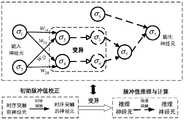
图2所示为本发明实施例提供的多元脉冲神经膜系统中各神经元关系示意图。FIG. 2 is a schematic diagram showing the relationship of each neuron in the multi-pulse neural membrane system provided by the embodiment of the present invention.

图3所示为本发明实施例提供的110kV智能变电站网络拓扑图。FIG. 3 is a network topology diagram of a 110kV smart substation provided by an embodiment of the present invention.

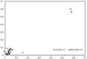
图4所示为本发明实施例提供的疑似故障元件的聚类结果示意图。FIG. 4 is a schematic diagram illustrating a clustering result of suspected faulty components according to an embodiment of the present invention.

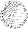
图5所示为本发明实施例提供的母线B1的基于mpSNPS的故障元件识别模型。FIG. 5 shows an mpSNPS-based fault component identification model of the bus bar B1 provided by the embodiment of the present invention.

具体实施方式Detailed ways

现在将参考附图来详细描述本发明的示例性实施方式。应当理解,附图中示出和描述的实施方式仅仅是示例性的,意在阐释本发明的原理和精神,而并非限制本发明的范围。Exemplary embodiments of the present invention will now be described in detail with reference to the accompanying drawings. It should be understood that the embodiments shown and described in the accompanying drawings are exemplary only, and are intended to illustrate the principles and spirit of the present invention, and not to limit the scope of the present invention.

本发明实施例提供了一种计及控制中心故障信息篡改的智能变电站故障诊断方法,如图1所示,包括以下步骤S1~S4:An embodiment of the present invention provides a fault diagnosis method for an intelligent substation that takes into account the tampering of fault information of a control center, as shown in FIG. 1 , including the following steps S1 to S4:

S1、采用模糊C均值聚类算法对智能变电站遥测量的归一化电压值进行聚类分析,并根据聚类结果确定疑似故障元件。S1. Use the fuzzy C-means clustering algorithm to perform cluster analysis on the normalized voltage values of the remote measurement of the smart substation, and determine the suspected faulty components according to the clustering results.

步骤S1包括以下分步骤S11~S13:Step S1 includes the following sub-steps S11 to S13:

S11、对智能变电站正常运行状态下的历史电压数据和未遭受攻击但故障状态下的历史电压数据进行处理,得到清洁数据,并提取智能变电站各母线和变压器的实时电压采样值。S11. Process the historical voltage data in the normal operation state of the smart substation and the historical voltage data in the unattacked but faulty state to obtain clean data, and extract real-time voltage sampling values of each busbar and transformer of the smart substation.

S12、当检测到智能变电站故障发生时,确定故障时间窗,并对智能变电站遥测量中的实时电压采样值进行归一化处理,得到归一化电压值。S12, when it is detected that a fault occurs in the smart substation, determine the fault time window, and normalize the real-time voltage sampling value in the remote measurement of the smart substation to obtain a normalized voltage value.

本发明实施例中,采用以下公式对智能变电站遥测量中的电压进行归一化处理,并提取0s、0.01s、0.03s和0.05s四个时刻的归一化电压值:In the embodiment of the present invention, the following formula is used to normalize the voltage in the remote measurement of the smart substation, and the normalized voltage values at four moments of 0s, 0.01s, 0.03s and 0.05s are extracted:

Figure BDA0002839151940000091

其中U'为归一化电压值,U为待归一化的实时电压采样值,Umax和Umin分别为清洁数据中历史电压值的最大值和最小值。Wherein U' is the normalized voltage value, U is the real-time voltage sampling value to be normalized, and Umax and Umin are the maximum and minimum values of the historical voltage values in the cleaning data, respectively.

S13、将归一化电压值作为模糊C均值聚类算法的输入进行数据聚类,根据聚类结果,将与聚类中心的距离大于距离阈值的母线或变压器以及与它们相连的馈线作为疑似故障元件。S13. Use the normalized voltage value as the input of the fuzzy C-means clustering algorithm to perform data clustering, and according to the clustering result, take the bus or transformer whose distance from the cluster center is greater than the distance threshold and the feeder connected to them as the suspected fault element.

S2、针对各疑似故障元件,采用幅值序列点约束和时间序列点约束计算得到序列点隶属矩阵D,并根据序列点隶属矩阵D计算得到各疑似故障元件的电压采样值合群系数,并根据电压采样值合群系数确定故障元件识别模型的输入数据。S2. For each suspected fault element, the sequence point membership matrix D is obtained by calculating the amplitude sequence point constraint and the time series point constraint, and the voltage sampling value group coefficient of each suspected fault element is calculated according to the sequence point membership matrix D, and according to the voltage The sampled value clustering coefficient determines the input data for the faulty component identification model.

步骤S2包括以下分步骤S21~S23:Step S2 includes the following sub-steps S21-S23:

S21、针对各疑似故障元件,采用幅值序列点约束

Figure BDA0002839151940000101
和时间序列点约束
Figure BDA0002839151940000102
计算得到序列点隶属矩阵D。S21. For each suspected faulty component, use the amplitude sequence point constraint
Figure BDA0002839151940000101
and time series point constraints
Figure BDA0002839151940000102
The sequence point membership matrix D is obtained by calculation.

序列点隶属矩阵D表示为:The sequence point membership matrix D is expressed as:

Figure BDA0002839151940000103

其中,

Figure BDA0002839151940000104
表示遥测量篡改评估因素,当智能变电站正常运作且遥测量没有被篡改时,由于小干扰、测量误差和传输错误等因素,在相同运行状态下,不同组别中的历史告警信息的电压采样值在某一时间内并不是一个确定值,而是在某一确定值附近波动的。当故障发生时,历史电压采样值的幅值分布将发生变化。因此,本发明实施例基于上述特征提出幅值序列点约束
Figure BDA0002839151940000105
和时间序列点约束
Figure BDA0002839151940000106
以判断遥测量是否遭受篡改。in,
Figure BDA0002839151940000104
Indicates the evaluation factor of telemetry tampering. When the smart substation is in normal operation and the telemetry has not been tampered with, due to factors such as small interference, measurement errors and transmission errors, the voltage sampling values of historical alarm information in different groups under the same operating state It is not a certain value at a certain time, but fluctuates around a certain value. When a fault occurs, the amplitude distribution of the historical voltage sampling values will change. Therefore, the embodiment of the present invention proposes an amplitude sequence point constraint based on the above characteristics
Figure BDA0002839151940000105
and time series point constraints
Figure BDA0002839151940000106
to determine whether telemetry has been tampered with.

幅值序列点约束

Figure BDA0002839151940000107
用于约束遥测量信息中的正序、负序和零序电压幅值,其定义如下:Amplitude Sequence Point Constraint
Figure BDA0002839151940000107
It is used to constrain the positive-sequence, negative-sequence and zero-sequence voltage amplitudes in telemetry information, and is defined as follows:

Figure BDA0002839151940000108

其中Vjk表示第k序电压(即正序、负序或零序电压)的第j个序列点的序电压值,k∈[1,n],j∈[1,l],l表示每种序电压的时间序列点数数目,n表示序电压的类型数目,本发明实施例中n=3;

Figure BDA0002839151940000109
Figure BDA00028391519400001010
分别表示对应时间序列点的历史电压采样值幅值的平均值和方差;μi表示对应第i个时间序列点的电压幅值,m表示历史电压的数目。where Vjk represents the sequence voltage value of the jth sequence point of the kth sequence voltage (ie positive sequence, negative sequence or zero sequence voltage), k∈[1,n], j∈[1,l], l denotes each The number of time-series points of the seed sequence voltage, n represents the number of types of sequence voltages, and n=3 in the embodiment of the present invention;
Figure BDA0002839151940000109
and
Figure BDA00028391519400001010
respectively represent the mean value and variance of the historical voltage sampling value amplitude corresponding to the time series point; μi represents the voltage amplitude corresponding to the i-th time series point, and m represents the number of historical voltages.

时间序列点约束

Figure BDA00028391519400001011
用于约束遥测量采样值信息中的正序、负序和零序电压时间戳的范围,其定义如下:time series point constraints
Figure BDA00028391519400001011
Used to constrain the range of positive-sequence, negative-sequence, and zero-sequence voltage timestamps in telemetry sampled value information, which is defined as follows:

Figure BDA00028391519400001012

其中Tjk表示第k序电压的第j个序列点时间戳,

Figure BDA00028391519400001013
Figure BDA00028391519400001014
分别表示对应时间序列点的历史时间戳的平均值和方差;ti表示第i个幅值序列点的时间戳。where Tjk represents the timestamp of the jth sequence point of the kth sequence voltage,
Figure BDA00028391519400001013
and
Figure BDA00028391519400001014
represent the mean and variance of the historical timestamps of the corresponding time series points, respectively; ti represents the timestamp of the ith amplitude sequence point.

S22、根据序列点隶属矩阵D计算得到各疑似故障元件的电压采样值合群系数p:S22, according to the sequence point membership matrix D, the group coefficient p of the voltage sampling values of each suspected fault element is obtained:

Figure BDA0002839151940000111

本发明实施例中,电压采样值合群系数p用于评估各疑似故障元件遥测量的不确定性程度。In the embodiment of the present invention, the grouping coefficient p of the voltage sampling value is used to evaluate the degree of uncertainty of the remote measurement of each suspected faulty component.

S23、判断各疑似故障元件的电压采样值合群系数p是否大于设定阈值,若是则说明该疑似故障元件的电压采样值合群系数较大,其实时电压采样值与其历史值高度匹配,这意味着实时遥测量信息的不确定性程度较低,此时将该疑似故障元件的电压采样值合群系数p、遥信量信息和时序信息作为故障元件识别模型的输入数据,以确定疑似元件是否发生故障。否则该疑似故障元件的实时采样值与其历史值匹配程度较低,这意味着遥测量信息的不确定性程度较高,此时电压采样值合群系数p将不会被使用,即对应该值的神经元不会触发,只将该疑似故障元件的遥信量信息和时序信息作为故障元件识别模型的输入数据。S23. Determine whether the grouping coefficient p of the voltage sampling value of each suspected faulty component is greater than the set threshold. If so, it means that the grouping coefficient of the voltage sampling value of the suspected faulty component is relatively large, and the real-time voltage sampling value is highly matched with its historical value, which means that The uncertainty of real-time telemetry information is relatively low. At this time, the voltage sampling value of the suspected faulty component, the group coefficient p, the remote signal quantity information and the timing information are used as the input data of the faulty component identification model to determine whether the suspected component is faulty. . Otherwise, the real-time sampling value of the suspected faulty component has a low degree of matching with its historical value, which means that the uncertainty of the telemetry information is high. At this time, the voltage sampling value grouping coefficient p will not be used, that is, the The neuron will not be triggered, and only the remote signal information and timing information of the suspected faulty component are used as the input data of the faulty component identification model.

S3、根据智能变电站的物理拓扑结构、保护装置配置和故障告警信息,为每一个疑似故障元件建立基于多元脉冲神经膜系统(Multi-pulse Spiking Neural P System,mpSNPS)的故障元件识别模型,并通过计算时序约束隶属度来修正各个故障元件识别模型中保护装置对应输入神经元的初始脉冲值。S3. According to the physical topology of the smart substation, the configuration of the protection device and the fault alarm information, a fault element identification model based on the Multi-pulse Spiking Neural P System (mpSNPS) is established for each suspected fault element, and a fault element identification model is established through the Multi-pulse Spiking Neural P System (mpSNPS). The membership degree of timing constraints is calculated to correct the initial pulse value of the protection device corresponding to the input neuron in each fault element identification model.

本发明实施例中,基于多元脉冲神经膜系统的故障元件识别模型∏具体为:In the embodiment of the present invention, the fault component identification model ∏ based on the multi-pulse neural membrane system is specifically:

∏=(A,syn,σ1,...,σm,in,out)∏=(A,syn,σ1 ,...,σm ,in,out)

其中A={a}表示神经脉冲的集合,a表示一个神经脉冲。where A={a} represents a set of nerve impulses, and a represents a nerve impulse.

syn={(i,j)|1≤i,j≤m∧i≠j}表示突触的集合,如果(i,j)∈syn,那么神经元σi是σj的突触前神经元,或者说σj为σi的突触后神经元。syn包括时序突触和推理突触,其中时序突触负责连接时序突触前神经元和时序突触后神经元,其作用为利用时标信息修正输入神经元的初始脉冲值,即保护装置的动作置信度;推理突触负责连接推理神经元,其作用为推理、计算其他神经元的脉冲值,以确定故障元件;时序突触通过目标智能变电站中保护设备之间的保护格局和时序约束信息生成,推理突触基于Dempster组合规则生成。syn={(i,j)|1≤i,j≤m∧i≠j} represents the set of synapses, if (i,j)∈syn, then neuron σi is the presynaptic neuron of σj , or σj is the postsynaptic neuron of σi . syn includes temporal synapses and inference synapses, where temporal synapses are responsible for connecting temporal presynaptic neurons and temporal postsynaptic neurons, and their role is to use the time scale information to correct the initial pulse value of the input neuron, that is, the protection device's initial pulse value. Action confidence; reasoning synapses are responsible for connecting reasoning neurons, and their functions are to reason and calculate the pulse values of other neurons to determine faulty components; timing synapses pass the protection pattern and timing constraint information between protection devices in the target smart substation Generating, inferential synapses are generated based on Dempster combinatorial rules.

σ1,…,σm为故障元件识别模型∏中的m个神经元,其包括时序突触前神经元σi=(Xi,wiji,ri)、时序突触后神经元σj=(Yjj,rj)和推理神经元σp=(Upp,rp),其中1≤i≤k1,k1+1≤j≤k1+k2,k1+k2+1≤p≤m,k1+k2+k3=m,k1,k2和k3分别表示时序突触前神经元、时序突触后神经元和推理神经元的数目。σ1 ,...,σm are the mneurons in the fault element identification model , which include thesequential element σj =(Yjj ,rj ) and inference neuron σp =(Upp ,rp ), where 1≤i≤k1 ,k1 +1≤j≤k1 + k2 , k1 +k2 +1≤p≤m,k1 +k2 +k3 =m, k1 , k2 and k3 represent the temporal presynaptic neuron, the temporal postsynaptic neuron and the Number of inference neurons.

本发明实施例中,三种神经元之间的关系如图2所示,其中“变异”表示在采用时序突触修正完输入神经元的初始脉冲值后,时序突触前神经元将变异为mpSNPS模型中的一部分推理神经元,模型中的另一部分推理神经元将来自环境;变异过程、时序突触和推理突触分别用虚线空心箭头、实线实心箭头和虚线实心箭头表示。需要注意的是,mpSNPS中来自环境的推理神经元是输入神经元,其脉冲值对应步骤S2中获得的电压采样值合群系数p;由时序突触后神经元变异而来的推理神经元也是输入神经元,其对应于目标智能变电站中的保护装置(即保护继电器或断路器),因此其脉冲值等于对应保护装置的动作置信度,如表1所示。一个输出神经元则表示一个疑似故障元件,其脉冲值由mpSNPS的多元脉冲矩阵推理算法计算获得,用于确定该疑似故障元件是否真的发生故障。In the embodiment of the present invention, the relationship between the three types of neurons is shown in Figure 2, where "variation" means that after the initial pulse value of the input neuron is corrected by using the time series synapse, the time series presynaptic neuron will mutate into A part of the inference neurons in the mpSNPS model, and the other part of the inference neurons in the model will come from the environment; the mutation process, the temporal synapse, and the inference synapse are represented by dashed hollow arrows, solid solid arrows, and dashed solid arrows, respectively. It should be noted that the inference neuron from the environment in mpSNPS is the input neuron, and its pulse value corresponds to the grouping coefficient p of the voltage sampling value obtained in step S2; the inference neuron mutated from the sequential post-synaptic neuron is also the input. Neuron, which corresponds to the protection device (ie, protection relay or circuit breaker) in the target smart substation, so its pulse value is equal to the action confidence of the corresponding protection device, as shown in Table 1. An output neuron represents a suspected faulty element, and its pulse value is calculated by the multivariate pulse matrix inference algorithm of mpSNPS to determine whether the suspected faulty element really fails.

表1保护继电器和断路器动作置信度Table 1 Protection relay and circuit breaker action confidence

Figure BDA0002839151940000121

时序突触前神经元σi的多元脉冲值由二元组Xi={αi,ti}表示,其中αi为一元脉冲值,取值为[0,1]上的实数,表示对应于σi的保护装置的动作置信度;ti为二元脉冲值,表示该保护装置动作时SOE事件顺序记录中的时间戳信息;当时序突触前神经元σi对应保护装置未动作或告警信息丢失时,取ti=1。The multivariate pulse value of the temporal presynaptic neuron σi is represented by the binary group Xi ={αi ,ti }, where αi is the unary pulse value, which is a real number on [0,1], indicating that the corresponding The action confidence of the protective device at σi ; ti is the binary pulse value, indicating the time stamp information in theSOE event sequence record when the protective device acts; When the alarm information is lost, take ti =1.

时序突触后神经元σj的多元脉冲值由二元组

Figure BDA0002839151940000122
表示,其中βj
Figure BDA0002839151940000123
分别表示采用时序信息修正警报信息后,与时序突触后神经元σj对应的保护装置的动作置信度和动作非置信度,两者的取值皆为[0,1]上的实数。The multivariate spike values of the temporal postsynaptic neuronσj are composed of two-tuples
Figure BDA0002839151940000122
represents, where βj and
Figure BDA0002839151940000123
Respectively represent the action confidence and action non-confidence of the protection device corresponding to the post-synaptic neuron σj after the timing information is used to correct the alarm information, both of which are real numbers in [0,1].

推理神经元σp的多元脉冲值由二元组

Figure BDA0002839151940000124
表示,其中θp
Figure BDA0002839151940000125
为在计算过程中得到的取值在区间[0,1]上的实数。The multivariate spike value of the inference neuronσp consists of two-tuples
Figure BDA0002839151940000124
represents, where θp and
Figure BDA0002839151940000125
is a real number in the interval [0,1] obtained during the calculation.

wij表示神经元时序突触前神经元σi到时序突触后神经元σj的有向时序突触权重,其计算公式为:

Figure BDA0002839151940000126
其中sij表示σi到σj的有向连接,若σi到σj存在时序突触,则sij=1,否则sij=0;λj为wij的时序约束隶属度,表示与σj相连的σi的脉冲值对于保护装置之间时序约束的满足程度。若λj越大,则表示对应脉冲值满足时序约束的程度越高,这意味着wij对应突触所携带的信息对故障元件的识别结果的影响越大。wij represents the directional timing synapse weight from the neuron timing pre-synaptic neuron σi to the timing post-synaptic neuron σj , and its calculation formula is:
Figure BDA0002839151940000126
where sij represents the directed connection from σi to σj , if there is a temporalsynapse between σi and σj , then sij =1, otherwisesij= 0; The degree of satisfaction of the pulse value of σi connected to σj to the timing constraints between protection devices. If λj is larger, it indicates that the corresponding pulse value satisfies the higher degree of timing constraints, which means that the information carried by the corresponding synapse of wij has a greater influence on the identification result of the faulty element.

εijp分别为神经元时序突触前神经元σi、时序突触后神经元σj和推理神经元σp的点火阀值,本发明实施例中,由于保护装置的最低动作置信度为0.2,设定εi=εj=εp=0。εi , εj , and εp are respectively the firing thresholds of the neuron sequential pre-synaptic neuron σi , the sequential post-synaptic neuron σj and the inference neuron σp . The lowest action confidence is 0.2, and εijp =0 is set.

ri为时序突触前神经元σi的点火规则,其形式为

Figure BDA0002839151940000131
其点火条件为E={α>εi},表示当且仅当时序突触前神经元σi的初始脉冲值大于εi时,才能执行规则ri;此时,σi将消耗一个位势值为{α,t}的脉冲a{α,t},产生并向其突触后神经元传递一个位势值为
Figure BDA0002839151940000132
的新脉冲
Figure BDA0002839151940000133
其中
Figure BDA0002839151940000134
ri is the firing rule of temporal presynaptic neuron σi in the form of
Figure BDA0002839151940000131
Its firing condition is E={α>εi }, which means that the ruleri can be executed if and only when the initial pulse value of the timing presynaptic neuron σi is greater than εi ; at this time, σi will consume one bit A pulse a{α,t} with potential {α,t} generates and transmits a potential value to its postsynaptic neuron
Figure BDA0002839151940000132
new pulse
Figure BDA0002839151940000133
in
Figure BDA0002839151940000134

rj为时序突触后神经元σj的点火规则,若时序突触后神经元σj后面连接的是推理突触,则它将变异为推理神经元σp来推理和计算神经元的脉冲值,在此情况下,rj与rp一致;否则σj进入休眠状态,不再参与后续任何计算。rj is the firing rule of the temporal post-synaptic neuron σj . If the temporal post-synaptic neuron σj is connected to an inference synapse, it will mutate into an inference neuron σp to infer and calculate the neuron’s impulses. value, in this case, rj is consistent with rp ; otherwise, σj enters a dormant state and does not participate in any subsequent calculations.

rp为推理神经元σp的点火规则,其形式为

Figure BDA0002839151940000135
其点火条件为E={θ>0∧g≤k3-1},表示当且仅当脉冲值θ大于0且多元脉冲矩阵推理算法的推理步骤不超过k3-1时,才能执行规则rp;此时,σp将消耗一个位势值为
Figure BDA0002839151940000136
的脉冲
Figure BDA0002839151940000137
产生并向其突触后神经元传递一个位势值为
Figure BDA0002839151940000138
的新脉冲
Figure BDA0002839151940000139
其中:rp is the firing rule of the inference neuron σp in the form of
Figure BDA0002839151940000135
The ignition condition is E={θ>0∧g≤k3 -1}, which means that the rule r can be executed if and only when the pulse value θ is greater than 0 and the reasoning step of the multivariate pulse matrix inference algorithm does not exceed k3 -1p ; at this time, σp will consume a potential value of
Figure BDA0002839151940000136
the pulse
Figure BDA0002839151940000137
generates and transmits a potential value to its postsynaptic neuron
Figure BDA0002839151940000138
new pulse
Figure BDA0002839151940000139
in:

Figure BDA00028391519400001310

Figure BDA00028391519400001311

若一个推理神经元后面连接的是推理突触,则其参与其他神经元脉冲值的推理和计算神经元;否则,该推理神经元是一个输出神经元,并将其脉冲值输出到环境中。If an inference neuron is followed by an inference synapse, it participates in the inference and calculation of the impulse values of other neurons; otherwise, the inference neuron is an output neuron and outputs its impulse value to the environment.

Figure BDA00028391519400001312
分别表示多元脉冲神经膜系统的输入和输出神经元集合。
Figure BDA00028391519400001312
represent the input and output neuron sets of the multivariate spiking neural membrane system, respectively.

本发明实施例中,时序约束隶属度的计算公式为:In the embodiment of the present invention, the calculation formula of the timing constraint membership is:

Figure BDA0002839151940000141

其中λAB表示故障事件A和B的时序约束隶属度,且故障事件A发生在B之前,t为故障的时间戳信息,

Figure BDA0002839151940000142
表示时序约束,其表示形式为:
Figure BDA0002839151940000143
tA和tB分别表示故障事件A和B的时间戳,
Figure BDA0002839151940000144
Figure BDA0002839151940000145
分别表示
Figure BDA0002839151940000146
的下限和上限;若故障事件A没有时间戳,则tA=-1且其与故障事件B的时间距离为
Figure BDA0002839151940000147
where λAB represents the timing constraint membership of fault events A and B, and fault event A occurs before B, t is the timestamp information of the fault,
Figure BDA0002839151940000142
Represents timing constraints, and its representation is:
Figure BDA0002839151940000143
tA and tB represent the timestamps of fault events A and B, respectively,
Figure BDA0002839151940000144
and
Figure BDA0002839151940000145
Respectively
Figure BDA0002839151940000146
The lower and upper bounds of
Figure BDA0002839151940000147

本发明实施例中,用故障时间戳信息和故障时序约束

Figure BDA0002839151940000148
来描述故障事件的时间特征。各类保护装置的延时区间和
Figure BDA0002839151940000149
的上下限是由保护装置的动作时间逻辑得到,不同保护装置的延时区间如表2所示。In this embodiment of the present invention, the fault time stamp information and the fault timing constraint are used
Figure BDA0002839151940000148
to describe the temporal characteristics of fault events. The delay interval of various protection devices and
Figure BDA0002839151940000149
The upper and lower limits are obtained from the action time logic of the protection device, and the delay interval of different protection devices is shown in Table 2.

表2不同保护装置的延时区间Table 2 Delay interval of different protection devices

事件event延时区间/msDelay interval/ms故障Fault00主保护继电器main protection relay[10,40][10,40]第一后备保护继电器First backup protection relay[310,340][310,340]第二后备保护继电器Second backup protection relay[510,540][510,540]断路器breaker[20,40][20,40]

S4、通过多元脉冲矩阵推理算法(Multi-pulse Matrix Reasoning Algorithm,MMRA)求解基于多元脉冲神经膜系统的故障元件识别模型,得到疑似故障元件的故障诊断结果。S4. Solve the fault element identification model based on the multi-pulse neural membrane system by using the Multi-pulse Matrix Reasoning Algorithm (MMRA), and obtain the fault diagnosis result of the suspected fault element.

多元脉冲矩阵推理算法包括以下步骤A1~A8:The multivariate impulse matrix inference algorithm includes the following steps A1-A8:

A1、设置推理步数g=0。A1. Set the number of inference steps g=0.

A2、对于每个时序突触前神经元,采用以下公式计算其时序约束隶属度λjA2. For each timing presynaptic neuron, use the following formula to calculate its timing constraint membership degree λj :

Figure BDA00028391519400001410

Figure BDA00028391519400001411
表示时序约束,t-和t+分别表示
Figure BDA00028391519400001412
的下限和上限。
Figure BDA00028391519400001411
represent timing constraints,t- and t+ , respectively
Figure BDA00028391519400001412
lower and upper bounds.

A3、根据时序约束隶属度λj计算每个时序突触前神经元的时序突触权重wijA3. Calculate the timing synaptic weight wij of each timing presynaptic neuron according to the timing constraint membership degree λj :

Figure BDA00028391519400001413

A4、判断每个时序突触前神经元是否满足点火条件,若是则进入步骤A5,否则时序突触前神经元不点火,并且记录其当前脉冲值为0,并进入步骤A6。A4. Determine whether each timing presynaptic neuron satisfies the ignition condition, if so, go to step A5, otherwise the timing presynaptic neuron does not fire, and record its current pulse value as 0, and enter step A6.

A5、根据

Figure BDA0002839151940000151
计算时序突触后神经元的脉冲值,进入步骤A6。A5. According to
Figure BDA0002839151940000151
Calculate the pulse value of the post-synaptic neuron in the time series, and go to step A6.

A6、对于每个推理神经元,判断推理步数g是否小于k3-1,若是则进入步骤A7,否则算法结束,得到输出神经元的脉冲值。A6. For each inference neuron, judge whether the number of inference steps g is less than k3 -1, if so, go to step A7, otherwise the algorithm ends, and the pulse value of the output neuron is obtained.

A7、判断每个推理神经元是否满足点火条件,若是则进入步骤A8,否则推理神经元不点火,记录其当前脉冲值为0,返回步骤A6。A7. Determine whether each inference neuron satisfies the ignition condition, if so, go to step A8, otherwise the inference neuron does not fire, record its current pulse value as 0, and return to step A6.

A8、推理神经元点火并根据

Figure BDA0002839151940000152
计算其脉冲值,返回步骤A6。A8. Inference neurons fire and fire according to
Figure BDA0002839151940000152
Calculate its pulse value, and return to step A6.

多元脉冲矩阵推理算法中涉及的向量、矩阵与运算算子含义如下:The meanings of vectors, matrices and operators involved in the multivariate impulse matrix inference algorithm are as follows:

Figure BDA0002839151940000153
表示时序突触前神经元的一元脉冲值向量,其中αi为第i个时序突触前神经元的一元脉冲值,1≤i≤k1
Figure BDA0002839151940000153
Represents the vector of unary spike values of the temporal presynaptic neuron, where αi is the unary spike value of the ith temporal presynaptic neuron, 1≤i≤k1 .

Figure BDA0002839151940000154
表示时序突触前神经元的二元脉冲值向量,其中ti为第i个时序突触前神经元的二元脉冲值。
Figure BDA0002839151940000154
represents the binary spike value vector of the temporal presynaptic neuron, where ti is the binary spike value of the ith temporal presynaptic neuron.

Figure BDA0002839151940000155
表示时序突触后神经元的一元脉冲值向量,其中βj为第j个时序突触后神经元的一元脉冲值,k1+1≤j≤k1+k2
Figure BDA0002839151940000155
represents the unary spike value vector of the temporal postsynaptic neuron, where βj is the unary spike value of the jth temporal postsynaptic neuron, k1 +1≤j≤k1 +k2 .

Figure BDA0002839151940000156
表示时序突触后神经元的二元脉冲值向量,其中
Figure BDA0002839151940000157
为第j个时序突触后神经元的二元脉冲值。
Figure BDA0002839151940000156
represents a vector of binary spike values for temporal postsynaptic neurons, where
Figure BDA0002839151940000157
is the binary spike value of the jth time-series postsynaptic neuron.

Figure BDA0002839151940000158
表示推理神经元的一元脉冲值向量,其中θp为第p个推理神经元的脉冲值,k1+k2+1≤p≤m。
Figure BDA0002839151940000158
represents the unary spike value vector of the inference neuron, where θp is the spike value of the pth inference neuron, k1 +k2 +1≤p≤m.

Figure BDA0002839151940000159
表示推理神经元的二元脉冲值向量,其中
Figure BDA00028391519400001510
为第p个推理神经元的脉冲值。
Figure BDA0002839151940000159
represents a vector of binary spike values for an inference neuron, where
Figure BDA00028391519400001510
is the spike value of the pth inference neuron.

Figure BDA00028391519400001511
表示时序约束隶属度矩阵,其中λj表示wij的时序约束隶属度。
Figure BDA00028391519400001511
represents the timing constraint membership matrix, where λj represents the timing constraint membership of wij .

Figure BDA0002839151940000161
表示时序突触连接矩阵,其中sij为神经元σi到σj之间的有向突触连接关系,若神经元σi到σj之间存在突触连接,则sij=1,否则sij=0。
Figure BDA0002839151940000161
represents the temporal synaptic connection matrix, where sij is the directed synaptic connection relationship between neurons σi to σj , if there is a synaptic connection between neurons σi to σj , then sij =1, otherwisesij =0.

Figure BDA0002839151940000162
表示时序突触权重矩阵,表示时序神经元之间的突触权重,
Figure BDA0002839151940000163
表示神经元σi到σj的突触权重。
Figure BDA0002839151940000162
represents the temporal synapse weight matrix, which represents the synaptic weights between temporal neurons,
Figure BDA0002839151940000163
represents the synaptic weights of neurons σi to σj .

Figure BDA0002839151940000164
表示推理突触连接矩阵,其中bpq表示推理神经元之间的有向突触连接关系,若推理神经元之间有突触连接,则bpq=1,否则bpq=0,k1+k2+1≤p≤m,1≤q≤m。
Figure BDA0002839151940000164
represents the inference synaptic connection matrix, where bpq represents the directed synaptic connection relationship between the inference neurons, if there is synaptic connection between the inference neurons, then bpq = 1, otherwise bpq = 0, k1 + k2 +1≤p≤m, 1≤q≤m.

上标T表示向量和矩阵的转置,下标g表示推理步数。The superscript T represents the transpose of vectors and matrices, and the subscript g represents the number of inference steps.

Figure BDA0002839151940000165
则多元脉冲矩阵推理算法中相关算子定义如下:make
Figure BDA0002839151940000165
Then the correlation operator in the multivariate impulse matrix inference algorithm is defined as follows:

一元脉冲值推理算子

Figure BDA0002839151940000166
定义为:Unary impulse value inference operator
Figure BDA0002839151940000166
defined as:

Figure BDA0002839151940000167

若θ1=0∧θ2≠0,则

Figure BDA0002839151940000168
If θ1 =0∧θ2 ≠0, then
Figure BDA0002839151940000168

二元脉冲值推理算子

Figure BDA0002839151940000169
定义为:Binary impulse value inference operator
Figure BDA0002839151940000169
defined as:

Figure BDA00028391519400001610

若θ1=0∧θ2≠0,则

Figure BDA00028391519400001611
If θ1 =0∧θ2 ≠0, then
Figure BDA00028391519400001611

其中θ12表示与θ性质相同的两个向量,θ12分别表示向量θ12中的元素,

Figure BDA00028391519400001612
分别表示与
Figure BDA00028391519400001613
性质相同的两个向量
Figure BDA00028391519400001614
中的元素,X,Y分别表示向量X,Y中的元素,O表示零向量。where θ1 , θ2 represent two vectors with the same properties as θ , θ1 , θ2 represent elements in vectors θ1 , θ2 respectively,
Figure BDA00028391519400001612
respectively represent and
Figure BDA00028391519400001613
Two vectors with the same properties
Figure BDA00028391519400001614
The elements in , X, Y represent the elements in the vector X, Y respectively, and O represents the zero vector.

加法算子

Figure BDA00028391519400001615
定义为:addition operator
Figure BDA00028391519400001615
defined as:

Figure BDA0002839151940000171

乘法算子

Figure BDA0002839151940000172
定义为:multiplication operator
Figure BDA0002839151940000172
defined as:

Figure BDA0002839151940000173

其中

Figure BDA0002839151940000178
Figure BDA0002839151940000174
分别表示wi1
Figure BDA0002839151940000175
中的非零元素。in
Figure BDA0002839151940000178
and
Figure BDA0002839151940000174
represent wi1 and
Figure BDA0002839151940000175
nonzero elements in .

本发明实施例中,通过故障元件识别模型∏输出神经元的脉冲值得到疑似故障元件的故障诊断结果,当且仅当输出神经元的一元脉冲值大于0.5,并且其二元脉冲值小于0.5时,判定输出神经元对应的疑似故障元件为故障元件,否则判定疑似故障元件不是故障元件。In the embodiment of the present invention, the fault diagnosis result of the suspected faulty element is obtained through the fault element identification model ∏ the pulse value of the output neuron, if and only if the unary pulse value of the output neuron is greater than 0.5 and the binary pulse value of the output neuron is less than 0.5 , determine that the suspected faulty component corresponding to the output neuron is a faulty component, otherwise it is determined that the suspected faulty component is not a faulty component.

下面以110kV智能变电站为诊断对象,以一个具体实验例为例,给出本发明的详细执行过程,以促进细节理解。In the following, the 110kV intelligent substation is taken as the diagnosis object, and a specific experimental example is taken as an example to give a detailed implementation process of the present invention to facilitate detailed understanding.

图3为110kV智能变电站网络拓扑图,其中预设故障情景和故障识别元件结果如表3所示,其中◇表示对应故障信息丢失,°表示对应故障信息被篡改。Figure 3 is a network topology diagram of a 110kV smart substation, in which the preset fault scenarios and the results of fault identification components are shown in Table 3, where ◇ means that the corresponding fault information is lost, and ° means that the corresponding fault information has been tampered with.

表3预设故障情景与故障元件识别结果Table 3 Preset fault scenarios and fault component identification results

Figure BDA0002839151940000176

首先,在故障发生后,基于表4中的数据以及变电站历史操作数据,采用模糊C均值算法寻找疑似故障元件,聚类结果如图4所示。First, after the fault occurs, based on the data in Table 4 and the historical operation data of the substation, the fuzzy C-means algorithm is used to find the suspected faulty components, and the clustering results are shown in Figure 4.

表4遥测量信息中的电压Table 4 Voltage in telemetry information

Figure BDA0002839151940000177

Figure BDA0002839151940000181

母线B1的电压采样值合群系数为:The group coefficient of the voltage sampling value of bus B1 is:

Figure BDA0002839151940000182

同样地,可以得到L111的电压采样值合群系数,即pL111=0.0275。Similarly, the group coefficient of the voltage sampling value of L111 can be obtained, that is, pL111 =0.0275.

由上述分析可知,母线B1的电压采样值合群系数(即0.9778)很大,这意味着实时电压采样值信息被篡改的可能性很低。因此,母线B1的mpSNPS故障元件识别模型中对应电压采样值合群系数的神经元将被触发,即在母线B1的故障元件识别模型中同时使用电压采样值合群系数、遥信量信息和时序信息来确定其是否真的发生故障。同理可得,L111的mpSNPS故障元件识别模型中对应电压采样值合群系数的神经元不会被触发,因此其识别模型将只使用遥信量信息和时序信息。It can be seen from the above analysis that the group coefficient of the voltage sampling value of the bus B1 (ie, 0.9778) is very large, which means that the possibility of tampering with the real-time voltage sampling value information is very low. Therefore, in the mpSNPS fault element identification model of bus B1, the neuron corresponding to the group coefficient of the voltage sampling value will be triggered, that is, the group coefficient of the voltage sampling value, the remote signal information and the timing information are used simultaneously in the fault element identification model of the bus B1. Determine if it is actually malfunctioning. In the same way, the neuron corresponding to the group coefficient of the voltage sampling value in the mpSNPS fault component identification model of L111 will not be triggered, so the identification model will only use the remote signal information and timing information.

建立母线B1的mpSNPS故障元件识别模型,如图5所示,其形式化表示为:The mpSNPS fault component identification model of bus B1 is established, as shown in Figure 5, which is formally expressed as:

Π1=(A,syn,σ1,...,σ24,in,out)Π1 =(A,syn,σ1 ,...,σ24 ,in,out)

其中:in:

(1)A={a}表示神经脉冲的集合,a表示一个神经脉冲。(1) A={a} represents a set of nerve impulses, and a represents one nerve impulse.

(2)syn={ST,I},其中:(2) syn={ST ,I}, where:

ST={(1,9),(1,10),(1,11),(2,6),(2,7),(2,8),(3,6),(3,9),(3,12),(3,13),(4,7),(4,10),(4,12),(4,14),(5,8),(5,11),(5,13),(5,14)}表示时序突触之间的有向连接关系;I={(6,22),(7,21),(8,20),(9,19),(10,18),(11,17),(12,16),(13,15),(14,15),(15,16),(16,17),(17,18),(18,19),(19,20),(20,21),(21,22),(22,24),(23,24)}表示推理突触之间的有向连接关系。ST = {(1,9),(1,10),(1,11),(2,6),(2,7),(2,8),(3,6),(3,9 ),(3,12),(3,13),(4,7),(4,10),(4,12),(4,14),(5,8),(5,11), (5, 13), (5, 14)} represents the directed connection relationship between temporal synapses; I={(6,22),(7,21),(8,20),(9,19) ,(10,18),(11,17),(12,16),(13,15),(14,15),(15,16),(16,17),(17,18),( 18, 19), (19, 20), (20, 21), (21, 22), (22, 24), (23, 24)} represent the directed connection relationship between inference synapses.

(3)σ1,...,σ24是故障元件识别模型中的24个神经元,其中σ1,...,σ5为时序突触前神经元,表示母线B1的保护装置;σ6,...,σ14为时序突触后神经元,表示由时序约束隶属度λ修正后的保护装置动作信息,即遥信量信息;σ6,...,σ24为推理神经元,它们将对模型中其他神经元的脉冲值进行推理和计算,以找到故障元件,其中σ6,...,σ14是由时序突触后神经元变异而来的,σ23的脉冲值则取B1的电压采样值合群系数。(3)σ1 , .6 ,...,σ14 are temporal post-synaptic neurons, representing the action information of the protection device corrected by the temporal constraint membership degree λ, that is, the telesignal information; σ6 ,...,σ24 are inference neurons , they will reason and compute the spike values of other neurons in the model to find the faulty element, where σ6 ,...,σ14 is mutated from the temporal postsynaptic neuron, and the spike value of σ23 Then take the voltage sampling value of B1 as the group coefficient.

(4)in={σ1234523},out={σ24},故障元件的识别结果将由神经元σ24的脉冲值确定。(4) in={σ1234523 },out={σ24 }, the identification result of the faulty element will be determined by the pulse value of neuron σ24 .

然后执行多元脉冲矩阵推理算法来计算σ24的多脉冲值,当g=10时,推理结束。此时,σ24输出其多脉冲值(0.94,0.06),其表示母线B1的故障置信度为0.94,非置信度为0.06。因此,依据判定规则确定母线B1为故障元件。Then a multi-pulse matrix inference algorithm is performed to calculate the multi-pulse value of σ24 , and the inference ends when g=10. At this time, σ24 outputs its multi-pulse value (0.94, 0.06), which indicates that the failure confidence of bus B1 is 0.94, and the unconfidence is 0.06. Therefore, the bus bar B1 is determined to be the faulty element according to the decision rule.

本领域的普通技术人员将会意识到,这里所述的实施例是为了帮助读者理解本发明的原理,应被理解为本发明的保护范围并不局限于这样的特别陈述和实施例。本领域的普通技术人员可以根据本发明公开的这些技术启示做出各种不脱离本发明实质的其它各种具体变形和组合,这些变形和组合仍然在本发明的保护范围内。Those of ordinary skill in the art will appreciate that the embodiments described herein are intended to assist readers in understanding the principles of the present invention, and it should be understood that the scope of the present invention is not limited to such specific statements and embodiments. Those skilled in the art can make various other specific modifications and combinations without departing from the essence of the present invention according to the technical teachings disclosed in the present invention, and these modifications and combinations still fall within the protection scope of the present invention.

Claims (7)

Translated fromChinese
1.计及控制中心故障信息篡改的智能变电站故障诊断方法,其特征在于,包括以下步骤:1. The intelligent substation fault diagnosis method considering the tampering of the fault information of the control center, is characterized in that, comprises the following steps:S1、采用模糊C均值聚类算法对智能变电站遥测量的归一化电压值进行聚类分析,并根据聚类结果确定疑似故障元件;S1. Use the fuzzy C-means clustering algorithm to perform cluster analysis on the normalized voltage values of the remote measurement of the smart substation, and determine the suspected faulty components according to the clustering results;S2、针对各疑似故障元件,采用幅值序列点约束和时间序列点约束计算得到序列点隶属矩阵D,并根据序列点隶属矩阵D计算得到各疑似故障元件的电压采样值合群系数,并根据电压采样值合群系数确定故障元件识别模型的输入数据;S2. For each suspected fault element, the sequence point membership matrix D is obtained by calculating the amplitude sequence point constraint and the time series point constraint, and the voltage sampling value group coefficient of each suspected fault element is calculated according to the sequence point membership matrix D, and according to the voltage The sampling value clustering coefficient determines the input data of the faulty component identification model;S3、根据智能变电站的物理拓扑结构、保护装置配置和故障告警信息,为每一个疑似故障元件建立基于多元脉冲神经膜系统的故障元件识别模型,并通过计算时序约束隶属度来修正各个故障元件识别模型中保护装置对应输入神经元的初始脉冲值;S3. According to the physical topology of the smart substation, the configuration of the protection device and the fault alarm information, a fault element identification model based on the multi-pulse neural membrane system is established for each suspected fault element, and the identification of each fault element is corrected by calculating the timing constraint membership degree. The protection device in the model corresponds to the initial pulse value of the input neuron;S4、通过多元脉冲矩阵推理算法求解基于多元脉冲神经膜系统的故障元件识别模型,得到疑似故障元件的故障诊断结果;S4. Solve the fault element identification model based on the multi-pulse neural membrane system through the multi-pulse matrix inference algorithm, and obtain the fault diagnosis result of the suspected fault element;所述步骤S3中建立的基于多元脉冲神经膜系统的故障元件识别模型∏具体为:The fault component identification model ∏ based on the multi-pulse neural membrane system established in the step S3 is specifically:∏=(A,syn,σ1,…,σm,in,out)∏=(A,syn,σ1 ,…,σm ,in,out)其中A={a}表示神经脉冲的集合,a表示一个神经脉冲;where A={a} represents a set of nerve impulses, and a represents a nerve impulse;syn={(i,j)|1≤i,j≤m∧i≠j}表示突触的集合,syn包括时序突触和推理突触,其中时序突触负责连接时序突触前神经元和时序突触后神经元,其作用为利用时标信息修正输入神经元的初始脉冲值,即保护装置的动作置信度;推理突触负责连接推理神经元,其作用为推理、计算其他神经元的脉冲值,以确定故障元件;所述时序突触通过目标智能变电站中保护设备之间的保护格局和时序约束信息生成,所述推理突触基于Dempster组合规则生成;syn={(i,j)|1≤i,j≤m∧i≠j} represents a set of synapses, syn includes temporal synapses and inference synapses, where temporal synapses are responsible for connecting temporal presynaptic neurons and Temporal post-synaptic neuron, whose function is to use time-scale information to correct the initial pulse value of the input neuron, that is, the action confidence of the protection device; the reasoning synapse is responsible for connecting the reasoning neurons, and its function is to reason and calculate other neurons. The pulse value is used to determine the fault element; the time sequence synapse is generated by the protection pattern and time sequence constraint information between the protection devices in the target smart substation, and the reasoning synapse is generated based on the Dempster combination rule;σ1,…,σm为故障元件识别模型∏中的m个神经元,其包括时序突触前神经元σi=(Xi,wiji,ri)、时序突触后神经元σj=(Yjj,rj)和推理神经元σp=(Upp,rp),其中1≤i≤k1,k1+1≤j≤k1+k2,k1+k2+1≤p≤m,k1+k2+k3=m,k1,k2和k3分别表示时序突触前神经元、时序突触后神经元和推理神经元的数目;σ1 ,...,σm are m neurons in the fault element identification model , which includestemporalpresynapticneurons element σj =(Yjj ,rj ) and inference neuron σp =(Upp ,rp ), where 1≤i≤k1 ,k1 +1≤j≤k1 + k2 , k1 +k2 +1≤p≤m,k1 +k2 +k3 =m, k1 , k2 and k3 represent the temporal presynaptic neuron, the temporal postsynaptic neuron and the the number of inference neurons;时序突触前神经元σi的多元脉冲值由二元组Xi={αi,ti}表示,其中αi为一元脉冲值,取值为[0,1]上的实数,表示对应于σi的保护装置的动作置信度;ti为二元脉冲值,表示该保护装置动作时SOE事件顺序记录中的时间戳信息;当时序突触前神经元σi对应保护装置未动作或告警信息丢失时,取ti=1;The multivariate pulse value of the temporal presynaptic neuron σi is represented by the binary group Xi ={αi ,ti }, where αi is the unary pulse value, which is a real number in [0,1], indicating that the corresponding The action confidence of the protective device at σi ; ti is the binary pulse value, indicating the time stamp information in theSOE event sequence record when the protective device acts; When the alarm information is lost, take ti =1;时序突触后神经元σj的多元脉冲值由二元组
Figure FDA0003610922650000021
表示,其中βj
Figure FDA0003610922650000022
分别表示采用时序信息修正警报信息后,与时序突触后神经元σj对应的保护装置的动作置信度和动作非置信度,两者的取值皆为[0,1]上的实数;The multivariate spike values of the temporal postsynaptic neuronσj are composed of two-tuples
Figure FDA0003610922650000021
represents, where βj and
Figure FDA0003610922650000022
respectively represent the action confidence and action non-confidence of the protection device corresponding to the post-synaptic neuron σj after the time sequence information is used to correct the alarm information, both of which are real numbers in [0,1];推理神经元σp的多元脉冲值由二元组
Figure FDA0003610922650000023
表示,其中θp
Figure FDA0003610922650000024
为在计算过程中得到的取值在区间[0,1]上的实数;
The multivariate spike value of the inference neuronσp consists of two-tuples
Figure FDA0003610922650000023
represents, where θp and
Figure FDA0003610922650000024
is a real number in the interval [0,1] obtained in the calculation process;
wij表示神经元时序突触前神经元σi到时序突触后神经元σj的有向时序突触权重,其计算公式为:
Figure FDA0003610922650000025
其中sij表示σi到σj的有向连接,若σi到σj存在时序突触,则sij=1,否则sij=0;λj为wij的时序约束隶属度,表示与σj相连的σi的脉冲值对于保护装置之间时序约束的满足程度;
wij represents the directional timing synapse weight from the neuron timing pre-synaptic neuron σi to the timing post-synaptic neuron σj , and its calculation formula is:
Figure FDA0003610922650000025
where sij represents the directed connection from σi to σj , if there is a temporalsynapse between σi and σj , then sij =1, otherwise sij= 0; The degree to which the pulse value of σi connected to σj satisfies the timing constraints between protection devices;
εijp分别为神经元时序突触前神经元σi、时序突触后神经元σj和推理神经元σp的点火阀值,εi=εj=εp=0;εi , εj , and εp are the firing thresholds of the temporal presynaptic neuron σi , the temporal post-synaptic neuron σj and the inference neuron σp respectively, εijp =0 ;ri为时序突触前神经元σi的点火规则,其形式为
Figure FDA0003610922650000026
其点火条件为E={α>εi},表示当且仅当时序突触前神经元σi的初始脉冲值大于εi时,才能执行规则ri;此时,σi将消耗一个位势值为{α,t}的脉冲a{α,t},产生并向其突触后神经元传递一个位势值为
Figure FDA0003610922650000027
的新脉冲
Figure FDA0003610922650000028
其中
Figure FDA0003610922650000029
ri is the firing rule of temporal presynaptic neuron σi in the form of
Figure FDA0003610922650000026
Its ignition condition is E={α>εi }, which means that the ruleri can be executed if and only when the initial pulse value of the timing presynaptic neuron σi is greater than εi ; at this time, σi will consume one bit A pulse a{α,t} with potential {α,t} generates and transmits a potential value to its postsynaptic neuron
Figure FDA0003610922650000027
new pulse
Figure FDA0003610922650000028
in
Figure FDA0003610922650000029
rj为时序突触后神经元σj的点火规则,若时序突触后神经元σj后面连接的是推理突触,则它将变异为推理神经元σp来推理和计算神经元的脉冲值,在此情况下,rj与rp一致;否则σj进入休眠状态,不再参与后续任何计算;rj is the firing rule of the temporal post-synaptic neuron σj . If the temporal post-synaptic neuron σj is connected with an inference synapse, it will mutate into an inference neuron σp to infer and calculate the neuron’s impulse. value, in this case, rj is consistent with rp ; otherwise, σj enters the dormant state and does not participate in any subsequent calculations;rp为推理神经元σp的点火规则,其形式为
Figure FDA00036109226500000210
其点火条件为E={θ>0∧g≤k3-1},表示当且仅当脉冲值θ大于0且多元脉冲矩阵推理算法的推理步骤不超过k3-1时,才能执行规则rp;此时,σp将消耗一个位势值为
Figure FDA00036109226500000211
的脉冲
Figure FDA00036109226500000212
产生并向其突触后神经元传递一个位势值为
Figure FDA0003610922650000031
的新脉冲
Figure FDA0003610922650000032
其中:
rp is the firing rule of the inference neuron σp in the form of
Figure FDA00036109226500000210
The ignition condition is E={θ>0∧g≤k3 -1}, which means that the rule r can be executed if and only when the pulse value θ is greater than 0 and the inference steps of the multivariate pulse matrix inference algorithm do not exceed k3 -1p ; at this time, σp will consume a potential value of
Figure FDA00036109226500000211
the pulse
Figure FDA00036109226500000212
generates and transmits to its postsynaptic neuron a potential value of
Figure FDA0003610922650000031
new pulse
Figure FDA0003610922650000032
in:
Figure FDA0003610922650000033
Figure FDA0003610922650000034
若一个推理神经元后面连接的是推理突触,则其参与其他神经元脉冲值的推理和计算神经元;否则,该推理神经元是一个输出神经元,并将其脉冲值输出到环境中;If an inference neuron is connected to an inference synapse, it participates in the inference and calculation of the impulse values of other neurons; otherwise, the inference neuron is an output neuron and outputs its impulse value to the environment;
Figure FDA0003610922650000035
分别表示多元脉冲神经膜系统的输入和输出神经元集合;
Figure FDA0003610922650000035
represent the input and output neuron sets of the multi-spiking neural membrane system, respectively;
所述步骤S3中时序约束隶属度的计算公式为:The calculation formula of the timing constraint membership degree in the step S3 is:
Figure FDA0003610922650000036
其中λAB表示故障事件A和B的时序约束隶属度,且故障事件A发生在B之前,t为故障的时间戳信息,
Figure FDA0003610922650000037
表示时序约束,其表示形式为:
Figure FDA0003610922650000038
tA和tB分别表示故障事件A和B的时间戳,
Figure FDA0003610922650000039
Figure FDA00036109226500000310
分别表示
Figure FDA00036109226500000311
的下限和上限;若故障事件A没有时间戳,则tA=-1且其与故障事件B的时间距离为
Figure FDA00036109226500000312
where λAB represents the timing constraint membership of fault events A and B, and fault event A occurs before B, t is the timestamp information of the fault,
Figure FDA0003610922650000037
Represents timing constraints, and its representation is:
Figure FDA0003610922650000038
tA and tB represent the timestamps of fault events A and B, respectively,
Figure FDA0003610922650000039
and
Figure FDA00036109226500000310
Respectively
Figure FDA00036109226500000311
The lower and upper bounds of
Figure FDA00036109226500000312
所述步骤S4中的多元脉冲矩阵推理算法包括以下步骤:The multivariate impulse matrix inference algorithm in the step S4 includes the following steps:A1、设置推理步数g=0;A1. Set the number of inference steps g=0;A2、对于每个时序突触前神经元,采用以下公式计算其时序约束隶属度λjA2. For each timing presynaptic neuron, use the following formula to calculate its timing constraint membership degree λj :
Figure FDA00036109226500000313
Figure FDA00036109226500000314
表示时序约束,t-和t+分别表示
Figure FDA00036109226500000315
的下限和上限;
Figure FDA00036109226500000314
represent timing constraints,t- and t+ , respectively
Figure FDA00036109226500000315
lower and upper bounds;
A3、根据时序约束隶属度λj计算每个时序突触前神经元的时序突触权重wijA3. Calculate the timing synaptic weight wij of each timing presynaptic neuron according to the timing constraint membership degree λj :
Figure FDA00036109226500000316
A4、判断每个时序突触前神经元是否满足点火条件,若是则进入步骤A5,否则时序突触前神经元不点火,并且记录其当前脉冲值为0,并进入步骤A6;A4. Determine whether each timing presynaptic neuron satisfies the ignition condition, if so, go to step A5, otherwise the timing presynaptic neuron does not fire, and record its current pulse value as 0, and enter step A6;A5、根据
Figure FDA0003610922650000041
计算时序突触后神经元的脉冲值,进入步骤A6;
A5. According to
Figure FDA0003610922650000041
Calculate the pulse value of the post-synaptic neuron in the time series, and enter step A6;
A6、对于每个推理神经元,判断推理步数g是否小于k3-1,若是则进入步骤A7,否则算法结束,得到输出神经元的脉冲值;A6. For each inference neuron, judge whether the number of inference steps g is less than k3 -1, if so, go to step A7, otherwise the algorithm ends, and the pulse value of the output neuron is obtained;A7、判断每个推理神经元是否满足点火条件,若是则进入步骤A8,否则推理神经元不点火,记录其当前脉冲值为0,返回步骤A6;A7. Determine whether each inference neuron satisfies the ignition condition, if so, go to step A8, otherwise the inference neuron does not fire, record its current pulse value as 0, and return to step A6;A8、推理神经元点火并根据
Figure FDA0003610922650000042
计算其脉冲值,返回步骤A6;
A8. Inference neurons fire and fire according to
Figure FDA0003610922650000042
Calculate its pulse value and return to step A6;
所述多元脉冲矩阵推理算法中涉及的向量、矩阵与运算算子含义如下:The meanings of vectors, matrices and operators involved in the multivariate impulse matrix reasoning algorithm are as follows:
Figure FDA0003610922650000043
表示时序突触前神经元的一元脉冲值向量,其中αi为第i个时序突触前神经元的一元脉冲值,1≤i≤k1
Figure FDA0003610922650000043
represents the unary impulse value vector of the temporal presynaptic neuron, where αi is the unary impulse value of the i-th temporal presynaptic neuron, 1≤i≤k1 ;
Figure FDA0003610922650000044
表示时序突触前神经元的二元脉冲值向量,其中ti为第i个时序突触前神经元的二元脉冲值;
Figure FDA0003610922650000044
represents the binary spike value vector of the temporal presynaptic neuron, where ti is the binary spike value of the ith temporal presynaptic neuron;
Figure FDA0003610922650000045
表示时序突触后神经元的一元脉冲值向量,其中βj为第j个时序突触后神经元的一元脉冲值,k1+1≤j≤k1+k2
Figure FDA0003610922650000045
represents the unary pulse value vector of the temporal postsynaptic neuron, where βj is the unary pulse value of the jth temporal postsynaptic neuron, k1 +1≤j≤k1 +k2 ;
Figure FDA0003610922650000046
表示时序突触后神经元的二元脉冲值向量,其中
Figure FDA0003610922650000047
为第j个时序突触后神经元的二元脉冲值;
Figure FDA0003610922650000046
represents a vector of binary spike values for temporal postsynaptic neurons, where
Figure FDA0003610922650000047
is the binary pulse value of the jth sequential post-synaptic neuron;
Figure FDA0003610922650000048
表示推理神经元的一元脉冲值向量,其中θp为第p个推理神经元的脉冲值,k1+k2+1≤p≤m;
Figure FDA0003610922650000048
represents the unary spike value vector of the inference neuron, where θp is the spike value of the pth inference neuron, k1 +k2 +1≤p≤m;
Figure FDA0003610922650000049
表示推理神经元的二元脉冲值向量,其中
Figure FDA00036109226500000410
为第p个推理神经元的脉冲值;
Figure FDA0003610922650000049
represents a vector of binary spike values for an inference neuron, where
Figure FDA00036109226500000410
is the pulse value of the pth inference neuron;
Figure FDA00036109226500000411
表示时序约束隶属度矩阵,其中λj表示wij的时序约束隶属度;
Figure FDA00036109226500000411
represents the timing constraint membership matrix, where λj represents the timing constraint membership of wij ;
Figure FDA00036109226500000412
表示时序突触连接矩阵,其中sij为神经元σi到σj之间的有向突触连接关系,若神经元σi到σj之间存在突触连接,则sij=1,否则sij=0;
Figure FDA00036109226500000412
represents the temporal synaptic connection matrix, where sij is the directed synaptic connection relationship between neurons σi to σj , if there is a synaptic connection between neurons σi to σj , then sij =1, otherwisesij = 0;
Figure FDA0003610922650000051
表示时序突触权重矩阵,表示时序神经元之间的突触权重,
Figure FDA0003610922650000052
表示神经元σi到σj的突触权重;
Figure FDA0003610922650000051
represents the temporal synapse weight matrix, representing the synaptic weights between temporal neurons,
Figure FDA0003610922650000052
represents the synaptic weights of neurons σi to σj ;
Figure FDA0003610922650000053
表示推理突触连接矩阵,其中bpq表示推理神经元之间的有向突触连接关系,若推理神经元之间有突触连接,则bpq=1,否则bpq=0,k1+k2+1≤p≤m,1≤q≤m;
Figure FDA0003610922650000053
represents the inference synaptic connection matrix, where bpq represents the directed synaptic connection relationship between inference neurons, if there is synaptic connection between inference neurons, then bpq = 1, otherwise bpq = 0, k1 + k2 +1≤p≤m, 1≤q≤m;
上标T表示向量和矩阵的转置,下标g表示推理步数;The superscript T represents the transpose of vectors and matrices, and the subscript g represents the number of inference steps;
Figure FDA0003610922650000054
则多元脉冲矩阵推理算法中相关算子定义如下:
make
Figure FDA0003610922650000054
Then the correlation operator in the multivariate impulse matrix inference algorithm is defined as follows:
一元脉冲值推理算子
Figure FDA0003610922650000055
定义为:
Unary impulse value inference operator
Figure FDA0003610922650000055
defined as:
Figure FDA0003610922650000056
若θ1=0∧θ2≠0,则
Figure FDA0003610922650000057
If θ1 =0∧θ2 ≠0, then
Figure FDA0003610922650000057
二元脉冲值推理算子
Figure FDA0003610922650000058
定义为:
Binary impulse value inference operator
Figure FDA0003610922650000058
defined as:
Figure FDA0003610922650000059
若θ1=0∧θ2≠0,则
Figure FDA00036109226500000510
If θ1 =0∧θ2 ≠0, then
Figure FDA00036109226500000510
其中θ12表示与θ性质相同的两个向量,θ12分别表示向量θ12中的元素,
Figure FDA00036109226500000511
分别表示与
Figure FDA00036109226500000512
性质相同的两个向量
Figure FDA00036109226500000513
中的元素,X,Y分别表示向量X,Y中的元素,O表示零向量;
where θ1 , θ2 represent two vectors with the same properties as θ , θ1 , θ2 represent elements in vectors θ1 , θ2 respectively,
Figure FDA00036109226500000511
respectively represent and
Figure FDA00036109226500000512
Two vectors with the same properties
Figure FDA00036109226500000513
The elements in , X, Y represent the elements in the vector X, Y respectively, O represents the zero vector;
加法算子
Figure FDA00036109226500000514
定义为:
addition operator
Figure FDA00036109226500000514
defined as:
Figure FDA00036109226500000515
乘法算子
Figure FDA00036109226500000516
定义为:
multiplication operator
Figure FDA00036109226500000516
defined as:
Figure FDA0003610922650000061
其中
Figure FDA0003610922650000062
Figure FDA0003610922650000063
分别表示wi1
Figure FDA0003610922650000064
中的非零元素。
in
Figure FDA0003610922650000062
and
Figure FDA0003610922650000063
represent wi1 and
Figure FDA0003610922650000064
nonzero elements in .
2.根据权利要求1所述的智能变电站故障诊断方法,其特征在于,所述步骤S1包括以下分步骤:2. The intelligent substation fault diagnosis method according to claim 1, wherein the step S1 comprises the following sub-steps:S11、对智能变电站正常运行状态下的历史电压数据和未遭受攻击但故障状态下的历史电压数据进行处理,得到清洁数据,并提取智能变电站各母线和变压器的实时电压采样值;S11. Process the historical voltage data under the normal operation state of the smart substation and the historical voltage data under the unattacked but faulty state to obtain clean data, and extract the real-time voltage sampling values of each busbar and transformer of the smart substation;S12、当检测到智能变电站故障发生时,确定故障时间窗,并对智能变电站遥测量中的实时电压采样值进行归一化处理,得到归一化电压值;S12, when it is detected that a fault occurs in the smart substation, determine the fault time window, and normalize the real-time voltage sampling value in the remote measurement of the smart substation to obtain a normalized voltage value;S13、将归一化电压值作为模糊C均值聚类算法的输入进行数据聚类,根据聚类结果,将与聚类中心的距离大于距离阈值的母线或变压器以及与它们相连的馈线作为疑似故障元件。S13. Use the normalized voltage value as the input of the fuzzy C-means clustering algorithm to perform data clustering, and according to the clustering result, take the bus or transformer whose distance from the cluster center is greater than the distance threshold and the feeder connected to them as the suspected fault element.3.根据权利要求1所述的智能变电站故障诊断方法,其特征在于,所述步骤S12中对智能变电站遥测量中的电压进行归一化处理的方法具体为:3. The intelligent substation fault diagnosis method according to claim 1, wherein the method for normalizing the voltage in the remote measurement of the intelligent substation in the step S12 is specifically:采用以下公式对智能变电站遥测量中的电压进行归一化处理,并提取0s、0.01s、0.03s和0.05s四个时刻的归一化电压值:Use the following formula to normalize the voltage in the remote measurement of the smart substation, and extract the normalized voltage values at four times of 0s, 0.01s, 0.03s and 0.05s:
Figure FDA0003610922650000065
其中U'为归一化电压值,U为待归一化的实时电压采样值,Umax和Umin分别为清洁数据中历史电压值的最大值和最小值。Wherein U' is the normalized voltage value, U is the real-time voltage sampling value to be normalized, and Umax and Umin are the maximum and minimum values of the historical voltage values in the cleaning data, respectively.
4.根据权利要求1所述的智能变电站故障诊断方法,其特征在于,所述步骤S2包括以下分步骤:4. The intelligent substation fault diagnosis method according to claim 1, wherein the step S2 comprises the following sub-steps:S21、针对各疑似故障元件,采用幅值序列点约束
Figure FDA0003610922650000066
和时间序列点约束
Figure FDA0003610922650000067
计算得到序列点隶属矩阵D;
S21. For each suspected faulty component, use the amplitude sequence point constraint
Figure FDA0003610922650000066
and time series point constraints
Figure FDA0003610922650000067
Calculate the sequence point membership matrix D;
S22、根据序列点隶属矩阵D计算得到各疑似故障元件的电压采样值合群系数p;S22. Calculate the grouping coefficient p of the voltage sampling values of each suspected faulty element according to the sequence point membership matrix D;S23、判断各疑似故障元件的电压采样值合群系数p是否大于设定阈值,若是则将该疑似故障元件的电压采样值合群系数p、遥信量信息和时序信息作为故障元件识别模型的输入数据,否则将该疑似故障元件的遥信量信息和时序信息作为故障元件识别模型的输入数据。S23. Determine whether the grouping coefficient p of the voltage sampling values of each suspected faulty element is greater than the set threshold, and if so, take the grouping coefficient p, the remote signal quantity information and the timing information of the voltage sampling value of the suspected faulty element as the input data of the fault element identification model , otherwise the remote signal quantity information and timing information of the suspected faulty element are used as the input data of the faulty element identification model.
5.根据权利要求4所述的智能变电站故障诊断方法,其特征在于,所述步骤S21中序列点隶属矩阵D表示为:5. The intelligent substation fault diagnosis method according to claim 4, wherein the sequence point membership matrix D in the step S21 is expressed as:
Figure FDA0003610922650000071
其中,
Figure FDA0003610922650000072
表示遥测量篡改评估因素,幅值序列点约束
Figure FDA0003610922650000073
用于约束遥测量信息中的正序、负序和零序电压幅值,其定义如下:
in,
Figure FDA0003610922650000072
Indicates the telemetry tampering evaluation factor, the magnitude sequence point constraint
Figure FDA0003610922650000073
It is used to constrain the positive-sequence, negative-sequence and zero-sequence voltage amplitudes in telemetry information, and is defined as follows:
Figure FDA0003610922650000074
其中Vjk表示第k序电压的第j个序列点的序电压值,k∈[1,n],j∈[1,l],l表示每种序电压的时间序列点数数目,n表示序电压的类型数目,
Figure FDA0003610922650000075
Figure FDA0003610922650000076
分别表示对应时间序列点的历史电压采样值幅值的平均值和方差;μi表示对应第i个时间序列点的电压幅值,m表示历史电压的数目;
Where Vjk represents the sequence voltage value of the jth sequence point of the kth sequence voltage, k∈[1,n], j∈[1,l], l denotes the number of time series points of each sequence voltage, n denotes the sequence voltage number of voltage types,
Figure FDA0003610922650000075
and
Figure FDA0003610922650000076
respectively represent the average value and variance of the historical voltage sampling value amplitude corresponding to the time series point; μi represents the voltage amplitude corresponding to the i-th time series point, and m represents the number of historical voltages;
时间序列点约束
Figure FDA0003610922650000077
用于约束遥测量采样值信息中的正序、负序和零序电压时间戳的范围,其定义如下:
time series point constraints
Figure FDA0003610922650000077
Used to constrain the range of positive-sequence, negative-sequence, and zero-sequence voltage timestamps in telemetry sampled value information, which is defined as follows:
Figure FDA0003610922650000078
其中Tjk表示第k序电压的第j个序列点时间戳,
Figure FDA0003610922650000079
Figure FDA00036109226500000710
分别表示对应时间序列点的历史时间戳的平均值和方差;ti表示第i个幅值序列点的时间戳。
where Tjk represents the timestamp of the jth sequence point of the kth sequence voltage,
Figure FDA0003610922650000079
and
Figure FDA00036109226500000710
represent the mean and variance of the historical timestamps of the corresponding time series points, respectively; ti represents the timestamp of the ith amplitude sequence point.
6.根据权利要求5所述的智能变电站故障诊断方法,其特征在于,所述步骤S22中电压采样值合群系数p的计算公式为:6. The method for diagnosing faults in an intelligent substation according to claim 5, wherein the calculation formula of the voltage sampling value grouping coefficient p in the step S22 is:
Figure FDA00036109226500000711
7.根据权利要求1所述的智能变电站故障诊断方法,其特征在于,所述步骤S4中通过故障元件识别模型∏输出神经元的脉冲值得到疑似故障元件的故障诊断结果,当且仅当输出神经元的一元脉冲值大于0.5,并且其二元脉冲值小于0.5时,判定输出神经元对应的疑似故障元件为故障元件,否则判定疑似故障元件不是故障元件。7. The fault diagnosis method for smart substation according to claim 1, wherein in step S4, the fault diagnosis result of the suspected fault element is obtained by the fault element identification model ∏ outputting the pulse value of the neuron, if and only if the output When the unary pulse value of the neuron is greater than 0.5, and its binary pulse value is less than 0.5, it is determined that the suspected faulty element corresponding to the output neuron is a faulty element, otherwise it is determined that the suspected faulty element is not a faulty element.
CN202011485183.2A2020-12-162020-12-16 Fault diagnosis method of intelligent substation considering control center fault information tamperingActiveCN112710914B (en)

Priority Applications (1)

Application NumberPriority DateFiling DateTitle
CN202011485183.2ACN112710914B (en)2020-12-162020-12-16 Fault diagnosis method of intelligent substation considering control center fault information tampering

Applications Claiming Priority (1)

Application NumberPriority DateFiling DateTitle
CN202011485183.2ACN112710914B (en)2020-12-162020-12-16 Fault diagnosis method of intelligent substation considering control center fault information tampering

Publications (2)

Publication NumberPublication Date
CN112710914A CN112710914A (en)2021-04-27
CN112710914Btrue CN112710914B (en)2022-06-17

Family

ID=75543482

Family Applications (1)

Application NumberTitlePriority DateFiling Date
CN202011485183.2AActiveCN112710914B (en)2020-12-162020-12-16 Fault diagnosis method of intelligent substation considering control center fault information tampering

Country Status (1)

CountryLink
CN (1)CN112710914B (en)

Families Citing this family (4)

* Cited by examiner, † Cited by third party
Publication numberPriority datePublication dateAssigneeTitle
CN113609912B (en)*2021-07-082023-06-20西华大学 A Fault Diagnosis Method of Transmission Network Based on Multi-source Information Fusion
CN113484685B (en)*2021-07-162023-08-18西华大学 A Fault Diagnosis Method of Power Network Based on Sequence-organized P-system
CN113935370A (en)*2021-09-152022-01-14南方电网科学研究院有限责任公司 A method for judging mechanical faults of three-phase oil-immersed distribution transformers
CN114004360B (en)*2021-12-302022-04-01北京壬工智能科技有限公司Intelligent equipment diagnosis equipment and method based on fuzzy expert model

Citations (2)

* Cited by examiner, † Cited by third party
Publication numberPriority datePublication dateAssigneeTitle
CN106771846A (en)*2016-11-082017-05-31西华大学Power transmission line fault phase selection based on fuzzy reasoning pulse nerve membranous system
CN107292883A (en)*2017-08-022017-10-24国网电力科学研究院武汉南瑞有限责任公司A kind of PCNN power failure method for detecting area based on local feature

Family Cites Families (6)

* Cited by examiner, † Cited by third party
Publication numberPriority datePublication dateAssigneeTitle
US8990132B2 (en)*2010-01-192015-03-24James Ting-Ho LoArtificial neural networks based on a low-order model of biological neural networks
CN103336222B (en)*2013-06-062015-07-15西南交通大学Power system fault diagnosis method based on fuzzy reasoning pulse neurolemma system
US10983514B2 (en)*2016-05-092021-04-20Strong Force Iot Portfolio 2016, LlcMethods and systems for equipment monitoring in an Internet of Things mining environment
CN106447031A (en)*2016-09-272017-02-22西华大学Fault diagnosis method and apparatus based on interval value fuzzy spiking neural membrane system
CN106483425B (en)*2016-09-272019-09-03西华大学 Fault Diagnosis Method and Device of Impulse Neuromembrane System Based on Triangular Fuzzy Number
CN111413565B (en)*2020-04-162020-10-23西华大学Intelligent power grid fault diagnosis method capable of identifying and measuring tampering attack

Patent Citations (2)

* Cited by examiner, † Cited by third party
Publication numberPriority datePublication dateAssigneeTitle
CN106771846A (en)*2016-11-082017-05-31西华大学Power transmission line fault phase selection based on fuzzy reasoning pulse nerve membranous system
CN107292883A (en)*2017-08-022017-10-24国网电力科学研究院武汉南瑞有限责任公司A kind of PCNN power failure method for detecting area based on local feature

Non-Patent Citations (1)

* Cited by examiner, † Cited by third party
Title
一种基于局部特征的PCNN电力故障区域提取方法;谷凯凯 等;《计算机工程》;20180731;第44卷(第7期);第291-296页*

Also Published As

Publication numberPublication date
CN112710914A (en)2021-04-27

Similar Documents

PublicationPublication DateTitle
CN112710914B (en) Fault diagnosis method of intelligent substation considering control center fault information tampering
Appiah et al.Long short-term memory networks based automatic feature extraction for photovoltaic array fault diagnosis
CN111585948B (en)Intelligent network security situation prediction method based on power grid big data
CN112926023B (en)Power transmission network fault diagnosis method based on P system considering meteorological factors
EP3460496B1 (en)A method and apparatus for automatic localization of a fault
CN103336222B (en)Power system fault diagnosis method based on fuzzy reasoning pulse neurolemma system
ChanApplication of neural-network computing in intelligent alarm processing (power systems)
Jones et al.Photovoltaic system fault detection and diagnostics using Laterally Primed Adaptive Resonance Theory neural network
CN112345858B (en)Power grid fault diagnosis method for measuring false faults caused by tampering attack
CN111413565B (en)Intelligent power grid fault diagnosis method capable of identifying and measuring tampering attack
dos Santos Fonseca et al.Simultaneous fault section estimation and protective device failure detection using percentage values of the protective devices alarms
CN116205265A (en) A method and device for power grid fault diagnosis based on deep neural network
CN113256096B (en)Power grid fault diagnosis method considering false data injection attack
CN115856756A (en)Fault assessment method for electric energy metering box
Abu-Nassar et al.Early detection of cyber-physical attacks on electric vehicles fast charging stations using wavelets and deep learning
CN113609912B (en) A Fault Diagnosis Method of Transmission Network Based on Multi-source Information Fusion
Wilson et al.Detection and mitigation of cyberattacks against power measurement channels using LSTM neural networks
CN113204735B (en) Power Grid Fault Diagnosis Method Based on Stochastic Self-adjusting Impulse Neural P System
CN106569095B (en) A Grid Fault Diagnosis System Based on Weighted Average Dependency Classifier
CN114282608A (en)Hidden fault diagnosis and early warning method and system for current transformer
CN117744020A (en)Power distribution network power outage range identification method based on multi-source heterogeneous data fusion
Zhao et al.Research on cable fault detection algorithm based on improved neural network algorithm
CN112085043A (en) A kind of intelligent monitoring method and system for network security of substation
Bahrami et al.Digital twin based topology fingerprinting for detecting false data injection attacks in cyber-physical systems
Shan et al.Power system fault diagnosis based on logistic regression deep neural network

Legal Events

DateCodeTitleDescription
PB01Publication
PB01Publication
SE01Entry into force of request for substantive examination
GR01Patent grant
GR01Patent grant
TR01Transfer of patent right

Effective date of registration:20250916

Address after:No.106, Fengze Road, Nansha District, Guangzhou, Guangdong 510000

Patentee after:Wu Yuxin

Country or region after:China

Address before:610039 Chengdu City, Jinniu District Province, North Bridge Road, No.

Patentee before:XIHUA University

Country or region before:China


[8]ページ先頭

©2009-2025 Movatter.jp