CN112710873B - Wiring device and testing device - Google Patents
Wiring device and testing deviceDownload PDFInfo
- Publication number
- CN112710873B CN112710873BCN202011337967.0ACN202011337967ACN112710873BCN 112710873 BCN112710873 BCN 112710873BCN 202011337967 ACN202011337967 ACN 202011337967ACN 112710873 BCN112710873 BCN 112710873B
- Authority
- CN
- China
- Prior art keywords
- conductor
- switching roller
- wiring
- conductor bar
- switching
- Prior art date
- Legal status (The legal status is an assumption and is not a legal conclusion. Google has not performed a legal analysis and makes no representation as to the accuracy of the status listed.)
- Active
Links
Images


Classifications
- G—PHYSICS
- G01—MEASURING; TESTING
- G01R—MEASURING ELECTRIC VARIABLES; MEASURING MAGNETIC VARIABLES
- G01R1/00—Details of instruments or arrangements of the types included in groups G01R5/00 - G01R13/00 and G01R31/00
- G01R1/02—General constructional details
- G01R1/04—Housings; Supporting members; Arrangements of terminals
- G01R1/0408—Test fixtures or contact fields; Connectors or connecting adaptors; Test clips; Test sockets
- G01R1/0416—Connectors, terminals
- H—ELECTRICITY
- H01—ELECTRIC ELEMENTS
- H01R—ELECTRICALLY-CONDUCTIVE CONNECTIONS; STRUCTURAL ASSOCIATIONS OF A PLURALITY OF MUTUALLY-INSULATED ELECTRICAL CONNECTING ELEMENTS; COUPLING DEVICES; CURRENT COLLECTORS
- H01R13/00—Details of coupling devices of the kinds covered by groups H01R12/70 or H01R24/00 - H01R33/00
- H01R13/62—Means for facilitating engagement or disengagement of coupling parts or for holding them in engagement
- H01R13/629—Additional means for facilitating engagement or disengagement of coupling parts, e.g. aligning or guiding means, levers, gas pressure electrical locking indicators, manufacturing tolerances
- H01R13/62905—Additional means for facilitating engagement or disengagement of coupling parts, e.g. aligning or guiding means, levers, gas pressure electrical locking indicators, manufacturing tolerances comprising a camming member
Landscapes
- Physics & Mathematics (AREA)
- General Physics & Mathematics (AREA)
- Testing Electric Properties And Detecting Electric Faults (AREA)
Abstract
Translated fromChinese
Description
Translated fromChinese技术领域technical field
本发明涉及电力设备测试技术领域,特别是涉及接线装置及测试装置。The invention relates to the technical field of power equipment testing, in particular to a wiring device and a testing device.
背景技术Background technique
为保障电力系统的安全稳定运行,电力试验人员需定期对成套电容式电压互感器进行预防性试验,以评估电容式电压互感器性能是否良好。在电容式电压互感器二次端子箱内进行测试,必要步骤是拆接线操作,测试结束后,还需要及时将接线板的接线恢复,以确保其可靠性。针对不同的测试项目,需要跟换二次端子的接线,以满足试验条件。在更换二次端子接线的过程中,容易造成接线错误、接线不良等问题,从而影响测试数据的准确。在更换二次端子接线时,为保证被测试的电力装置正常运作,需对电容式电压互感器二次端子的恢复情况进行多个步骤检查确认,其中包括手绘接线图、拆线前后拍照对比、逐项填写拆接线表单及测量端子通断问题,投入人力及时间成本较多。In order to ensure the safe and stable operation of the power system, electric power test personnel need to regularly conduct preventive tests on the complete set of capacitor voltage transformers to evaluate whether the performance of the capacitor voltage transformers is good. To test in the secondary terminal box of the capacitive voltage transformer, the necessary step is to disassemble the wiring. After the test, it is necessary to restore the wiring of the terminal board in time to ensure its reliability. For different test items, it is necessary to change the wiring of the secondary terminal to meet the test conditions. In the process of replacing the wiring of the secondary terminal, it is easy to cause problems such as wiring errors and poor wiring, which will affect the accuracy of the test data. When replacing the wiring of the secondary terminal, in order to ensure the normal operation of the power device under test, it is necessary to check and confirm the recovery of the secondary terminal of the capacitive voltage transformer in multiple steps, including hand-drawn wiring diagrams, photographing comparisons before and after disconnection, Filling out the disconnection form and measuring the continuity of the terminals one by one requires a lot of manpower and time.
发明内容Contents of the invention
基于此,有必要针对传统的电容式电压互感器进行不同测试项目时,容易造成接线错误、投入人力和时间成本较多的问题,提供一种能够迅速准确接线、节省人力和时间的接线装置及测试装置。Based on this, it is necessary to provide a wiring device that can quickly and accurately connect and save manpower and time for the problems of wiring errors, manpower and time costs when performing different test items for traditional capacitive voltage transformers. test device.
本申请实施例提供一种接线装置,包括:An embodiment of the present application provides a wiring device, including:
导体棒组件;conductor bar assembly;
切换辊,设置有沿周向排布的多组所述导体棒组件,每组所述导体棒组件包括多个沿所述切换辊的轴向依次排布的导体棒;The switch roller is provided with multiple sets of conductor bar assemblies arranged in the circumferential direction, and each set of conductor bar assemblies includes a plurality of conductor bars arranged in sequence along the axial direction of the switch roller;
多个第一导体,与所述切换辊的外周面相对设置,并且所述多个第一导体沿所述切换辊的轴向依次排布;所述切换辊绕自身轴线转动时,能够选择地使所述多组导体棒组件中的任一组与多个所述第一导体相配合;所述导体棒组件与所述第一导体配合时,该组所述导体棒组件中的每个所述导体棒分别与对应的所述第一导体电连接;A plurality of first conductors are arranged opposite to the outer peripheral surface of the switching roller, and the plurality of first conductors are arranged in sequence along the axial direction of the switching roller; when the switching roller rotates around its own axis, it can be selectively Make any one of the multiple sets of conductor bar assemblies match with a plurality of the first conductors; when the conductor bar assemblies are matched with the first conductors, each set of the conductor bar assemblies in the set The conductor bars are respectively electrically connected to the corresponding first conductors;
安装箱,所述导体棒、切换辊以及第一导体位于所述安装箱内;an installation box, the conductor bar, the switching roller and the first conductor are located in the installation box;
第一线束,包括多个第一导线,所述第一导线的一端与所述第一导体电连接并一一对应;The first wire harness includes a plurality of first wires, one end of the first wires is electrically connected to the first conductors and corresponds to each other;
插头,包括多个插针,所述插针与所述第一导线的另一端电连接并一一对应;以及a plug, including a plurality of pins, and the pins are electrically connected to the other end of the first wire in one-to-one correspondence; and
第二线束,所述第二线束包括多个第二导线;每个所述导体棒分别与对应的所述第二导线电连接。A second wiring harness, the second wiring harness includes a plurality of second wires; each of the conductor bars is electrically connected to the corresponding second wires.
上述的接线装置用于连接电容电压互感器的二次端子箱与测试仪器,并用于对电容电压互感器进行预防性试验项目测试时,将插头插于二次端子箱,将第二线束与测试仪器的接线端电连接。在需要进行某一种试验项目时,可通过转动切换辊带动多组导体棒组件转动,使得该试验项目对应的导体棒组件与多个第一导体相配合,从而接线装置能够切换至该试验项目对应的接线模式,且电容电压互感器的二次端子箱与测试仪器能够电连接,接线方式迅速方便且能够准确切换至对应的接线模式,不易造成接线错误,且能够节省人力和时间。The above-mentioned wiring device is used to connect the secondary terminal box of the capacitor voltage transformer and the test instrument, and is used to test the preventive test items of the capacitor voltage transformer, insert the plug into the secondary terminal box, and connect the second wiring harness to the test instrument. The terminals of the instrument are electrically connected. When a certain test item is required, multiple groups of conductor bar assemblies can be driven to rotate by rotating the switching roller, so that the conductor bar assembly corresponding to the test item is matched with multiple first conductors, so that the wiring device can be switched to the test item The corresponding wiring mode, and the secondary terminal box of the capacitor voltage transformer can be electrically connected with the test instrument, the wiring mode is fast and convenient, and can be accurately switched to the corresponding wiring mode, which is not easy to cause wiring errors, and can save manpower and time.
在一实施例中,所述的接线装置还包括驱动机构,用于驱动所述切换辊转动。In one embodiment, the wiring device further includes a driving mechanism for driving the switching roller to rotate.
在一实施例中,所述的接线装置还包括:In one embodiment, the wiring device further includes:
减速机构,由所述驱动机构驱动,并用于带动所述切换辊转动;和/或,a reduction mechanism, driven by the driving mechanism, and used to drive the switching roller to rotate; and/or,
控制装置,用于控制所述驱动机构带动所述切换辊转动。The control device is used to control the driving mechanism to drive the switching roller to rotate.
在一实施例中,所述的接线装置还包括安装于所述安装箱的安装部,所述安装部与所述切换辊的外周面相对设置,所述多个第一导体安装于所述安装部。In one embodiment, the wiring device further includes a mounting portion mounted on the mounting box, the mounting portion is disposed opposite to the outer peripheral surface of the switching roller, and the plurality of first conductors are mounted on the mounting box. department.
在一实施例中,所述安装部具有内表面和与所述内表面相背设置的外表面,所述内表面与所述切换辊的外周面贴合;In one embodiment, the mounting part has an inner surface and an outer surface opposite to the inner surface, and the inner surface is attached to the outer peripheral surface of the switching roller;
所述内表面设有沿所述切换辊的轴向依次排布的多个切换槽;每个所述切换槽的延伸方向沿所述切换辊的周向;所述第一导体安装于所述切换槽内并与所述切换槽一一对应;所述导体棒位于各自对应的所述切换槽内并能够沿所述切换槽转动。The inner surface is provided with a plurality of switching grooves arranged in sequence along the axial direction of the switching roller; the extension direction of each switching groove is along the circumferential direction of the switching roller; the first conductor is installed on the The switching slots are in one-to-one correspondence with the switching slots; the conductor rods are located in the corresponding switching slots and can rotate along the switching slots.
在一实施例中,所述的接线装置还包括与所述第一导体一一对应的弹性卡组件,所述弹性卡组件安装于所述安装部并用于与所述导体棒卡接;所述导体棒与所述弹性卡组件卡接时能够与所述第一导体电连接;In one embodiment, the wiring device further includes an elastic clip assembly corresponding to the first conductor one by one, and the elastic clip assembly is installed on the installation part and is used for clipping with the conductor bar; The conductor bar can be electrically connected to the first conductor when it is engaged with the elastic clip assembly;
所述弹性卡组件具有用于容纳所述导体棒的卡接腔;所述卡接腔的两端分别具有开口,所述切换辊带动所述导体棒转动时,所述导体棒能够从所述卡接腔的一端开口进入所述卡接腔,并能够从所述卡接腔的另一端开口离开所述卡接腔。The elastic clamp assembly has a clamping cavity for accommodating the conductor rod; the two ends of the clamping cavity have openings respectively, and when the switching roller drives the conductor rod to rotate, the conductor rod can be opened from the clamping cavity. One end of the opening enters the fastening cavity, and the other end of the fastening cavity can leave the fastening cavity.
在一实施例中,所述弹性卡组件所采用的材料为弹性材料;或;In one embodiment, the elastic card component is made of elastic material; or;
所述弹性卡组件所采用的材料为金属材料,所述第一导体为所述弹性卡组件。The elastic card component is made of metal material, and the first conductor is the elastic card component.
在一实施例中,所述的接线装置还包括:In one embodiment, the wiring device further includes:
多个感应触点,设置于所述切换辊并沿所述切换辊的周向依次排布,所述感应触点与所述导体棒组件一一对应;和A plurality of sensing contacts are arranged on the switching roller and arranged in sequence along the circumference of the switching roller, and the sensing contacts are in one-to-one correspondence with the conductor bar assemblies; and
感应触头,所述切换辊带动多个所述感应触点转动时,能够使所述多个感应触点中的任一个与所述感应触头相配合;当选定的所述感应触点与所述感应触头相配合时,能够触发所述切换辊停止转动,所述切换辊停止转动时,该选定的所述感应触点对应的所述导体棒组件能够与多个所述第一导体相配合。Sensing contacts, when the switching roller drives a plurality of the sensing contacts to rotate, any one of the plurality of sensing contacts can be matched with the sensing contacts; when the selected sensing contacts When cooperating with the sensing contact, it can trigger the switching roller to stop rotating, and when the switching roller stops rotating, the conductor bar assembly corresponding to the selected sensing contact can be connected with a plurality of the first A conductor is matched.
在一实施例中,所述的接线装置还包括:固定杆和弹簧,所述弹簧一端与所述固定杆连接,另一端与所述感应触头连接;所述感应触点与所述感应触头配合时,所述弹簧的恢复力朝向所述感应触点。In one embodiment, the wiring device further includes: a fixed rod and a spring, one end of the spring is connected to the fixed rod, and the other end is connected to the sensing contact; the sensing contact is connected to the sensing contact When the heads are mated, the restoring force of the spring is directed towards the sensing contacts.
本申请另一实施例还提供一种测试装置,包括上述任一项所述的接线装置和测试仪器;每个所述导体棒分别与各自对应的所述第二导线的一端电连接;所述第二导线的另一端与所述测试仪器电连接,且所述第二导线与所述测试仪器的接线端一一对应。Another embodiment of the present application also provides a test device, including the wiring device described in any one of the above and a test instrument; each of the conductor bars is respectively electrically connected to one end of the corresponding second wire; the The other end of the second wire is electrically connected to the test instrument, and the second wire is in one-to-one correspondence with the terminals of the test instrument.
附图说明Description of drawings
图1为一实施例的测试装置的结构示意图;Fig. 1 is the structural representation of the test device of an embodiment;
图2为图1中的测试装置的接线装置的安装部的仰视图;Fig. 2 is the bottom view of the mounting part of the wiring device of the test device in Fig. 1;
图3为图2中的接线装置的弹性卡组件与导体棒的连接关系示意图;Fig. 3 is a schematic diagram of the connection relationship between the elastic card assembly and the conductor bar of the wiring device in Fig. 2;
图4为图1中A的放大图。Fig. 4 is an enlarged view of A in Fig. 1 .
具体实施方式Detailed ways
为使本发明的上述目的、特征和优点能够更加明显易懂,下面结合附图对本发明的具体实施方式做详细的说明。在下面的描述中阐述了很多具体细节以便于充分理解本发明。但是本发明能够以很多不同于在此描述的其它方式来实施,本领域技术人员可以在不违背本发明内涵的情况下做类似改进,因此本发明不受下面公开的具体实施例的限制。In order to make the above objects, features and advantages of the present invention more comprehensible, specific implementations of the present invention will be described in detail below in conjunction with the accompanying drawings. In the following description, numerous specific details are set forth in order to provide a thorough understanding of the present invention. However, the present invention can be implemented in many other ways different from those described here, and those skilled in the art can make similar improvements without departing from the connotation of the present invention, so the present invention is not limited by the specific embodiments disclosed below.
在本发明的描述中,需要理解的是,术语“中心”、“纵向”、“横向”、“长度”、“宽度”、“厚度”、“上”、“下”、“前”、“后”、“左”、“右”、“竖直”、“水平”、“顶”、“底”、“内”、“外”、“顺时针”、“逆时针”、“轴向”、“径向”、“周向”等指示的方位或位置关系为基于附图所示的方位或位置关系,仅是为了便于描述本发明和简化描述,而不是指示或暗示所指的装置或元件必须具有特定的方位、以特定的方位构造和操作,因此不能理解为对本发明的限制。In describing the present invention, it is to be understood that the terms "center", "longitudinal", "transverse", "length", "width", "thickness", "upper", "lower", "front", " Back", "Left", "Right", "Vertical", "Horizontal", "Top", "Bottom", "Inner", "Outer", "Clockwise", "Counterclockwise", "Axial" , "radial", "circumferential" and other indicated orientations or positional relationships are based on the orientations or positional relationships shown in the drawings, and are only for the convenience of describing the present invention and simplifying the description, rather than indicating or implying the referred device or Elements must have certain orientations, be constructed and operate in certain orientations, and therefore should not be construed as limitations on the invention.
此外,术语“第一”、“第二”仅用于描述目的,而不能理解为指示或暗示相对重要性或者隐含指明所指示的技术特征的数量。由此,限定有“第一”、“第二”的特征可以明示或者隐含地包括至少一个该特征。在本发明的描述中,“多个”的含义是至少两个,例如两个,三个等,除非另有明确具体的限定。In addition, the terms "first" and "second" are used for descriptive purposes only, and cannot be interpreted as indicating or implying relative importance or implicitly specifying the quantity of indicated technical features. Thus, the features defined as "first" and "second" may explicitly or implicitly include at least one of these features. In the description of the present invention, "plurality" means at least two, such as two, three, etc., unless otherwise specifically defined.
在本发明中,除非另有明确的规定和限定,术语“安装”、“相连”、“连接”、“固定”等术语应做广义理解,例如,可以是固定连接,也可以是可拆卸连接,或成一体;可以是机械连接,也可以是电连接;可以是直接相连,也可以通过中间媒介间接相连,可以是两个元件内部的连通或两个元件的相互作用关系,除非另有明确的限定。对于本领域的普通技术人员而言,可以根据具体情况理解上述术语在本发明中的具体含义。In the present invention, unless otherwise clearly specified and limited, terms such as "installation", "connection", "connection" and "fixation" should be understood in a broad sense, for example, it can be a fixed connection or a detachable connection , or integrated; it may be mechanically connected or electrically connected; it may be directly connected or indirectly connected through an intermediary, and it may be the internal communication of two components or the interaction relationship between two components, unless otherwise specified limit. Those of ordinary skill in the art can understand the specific meanings of the above terms in the present invention according to specific situations.
在本发明中,除非另有明确的规定和限定,第一特征在第二特征“上”或“下”可以是第一和第二特征直接接触,或第一和第二特征通过中间媒介间接接触。而且,第一特征在第二特征“之上”、“上方”和“上面”可是第一特征在第二特征正上方或斜上方,或仅仅表示第一特征水平高度高于第二特征。第一特征在第二特征“之下”、“下方”和“下面”可以是第一特征在第二特征正下方或斜下方,或仅仅表示第一特征水平高度小于第二特征。In the present invention, unless otherwise clearly specified and limited, the first feature may be in direct contact with the first feature or the first and second feature may be in direct contact with the second feature through an intermediary. touch. Moreover, "above", "above" and "above" the first feature on the second feature may mean that the first feature is directly above or obliquely above the second feature, or simply means that the first feature is higher in level than the second feature. "Below", "beneath" and "beneath" the first feature may mean that the first feature is directly below or obliquely below the second feature, or simply means that the first feature is less horizontally than the second feature.
需要说明的是,当元件被称为“固定于”或“设置于”另一个元件,它可以直接在另一个元件上或者也可以存在居中的元件。当一个元件被认为是“连接”另一个元件,它可以是直接连接到另一个元件或者可能同时存在居中元件。本文所使用的术语“垂直的”、“水平的”、“上”、“下”、“左”、“右”以及类似的表述只是为了说明的目的,并不表示是唯一的实施方式。It should be noted that when an element is referred to as being “fixed on” or “disposed on” another element, it may be directly on the other element or there may be an intervening element. When an element is referred to as being "connected to" another element, it can be directly connected to the other element or intervening elements may also be present. As used herein, the terms "vertical", "horizontal", "upper", "lower", "left", "right" and similar expressions are for the purpose of illustration only and are not intended to represent the only embodiment.
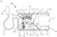
请参考图1,本申请实施例提供一种接线装置100。接线装置100包括:导体棒组件110、切换辊120、第一导体(未示出)、安装箱140、第一线束151、插头152以及第二线束153。导体棒111、切换辊120以及第一导体位设置于安装箱140内。Referring to FIG. 1 , an embodiment of the present application provides a
切换辊120设置有沿周向排布的多组导体棒组件110,每组导体棒组件110包括多个沿切换辊120的轴向依次排布的导体棒111。The
具体地,如图1所示,接线装置100还包括安装架121。安装架121固定在安装箱140的底壁。切换辊120通过安装架121安装于安装箱140内。切换辊120与安装架121可通过转轴(未示出)转动连接,从而切换辊120能够通过转轴绕自身轴线转动。Specifically, as shown in FIG. 1 , the
多组导体棒组件110设置在切换辊120的外周面上,并沿切换辊120的周向间隔排列。如图1所示,本实施例中导体棒组件110为三组,沿顺时针方向依次为第一组导体棒组件110、第二组导体棒组件110、第三组导体棒组件110。可以理解,导体棒组件110的数量也可以为两组、四组等其他数量。每组导体棒组件110包括多个导体棒111,多个导体棒111沿切换辊120的轴向依次排布,从而每组导体棒组件110排成一列。不同组的导体棒组件110可包括不同数量的导体棒111,也可包括相同数量的导体棒111。例如,在本实施例的三组导体棒组件110中,第一组导体棒组件110包括四根导体棒111,第二组导体棒组件110包括三根导体棒111,第三组导体棒组件110包括五根导体棒111。Multiple sets of
第一导体与切换辊120的外周面相对设置。多个第一导体沿切换辊120的轴向依次排布。切换辊120绕自身轴线转动时,能够选择地使多组导体棒组件110中的任一组与多个第一导体相配合。导体棒组件110与第一导体配合时,该组导体棒组件110中的每个导体棒111分别与对应的第一导体电连接。The first conductor is provided opposite to the outer peripheral surface of the switching
具体地,第一导体可以是导体块、导电触点等。如图1所示,本实施例中,接线装置100还包括安装部180,安装部180与安装箱140的内壁固定连接。可将多个第一导体安装于安装部180。Specifically, the first conductor may be a conductor block, a conductive contact, or the like. As shown in FIG. 1 , in this embodiment, the
切换辊120绕自身轴线转动时,多个第一导体固定不动,从而切换辊120带动多组导体棒组件110相对于第一导体转动。由于多个第一导体与切换辊120的外周面相对设置,因此,通过将切换辊120转动不同的角度,能够使不同组的导体棒组件110与多个第一导体配合。When the switching
第一导体的数量大于或等于每组导体棒组件110中的导体棒111的数量,从而,每组导体棒组件110与多个第一导体配合时,该组导体棒组件110中的每个导体棒111能够分别与各自对应的第一导体相接触,从而实现电连接。例如,第一导体的数量可以为五个。若第一组导体棒组件110与多个第一导体配合时,则第一组导体棒组件110中的四个导体棒111分别与各自对应的第一导体连接,从而四个导体棒111与四个第一导体电连接,剩余的一个第一导体则不连接导体棒111。若第三组导体棒组件110与多个第一导体配合时,则第三组导体棒组件110中的五个导体棒111与五个第一导体一一对应。The number of first conductors is greater than or equal to the number of conductor bars 111 in each set of
在本实施例中,接线装置100用于连接电容电压互感器的二次端子箱与测试仪器11(例如是介损仪等),以便通过测试仪器11对电容电压互感器进行预防性试验。In this embodiment, the
具体地,如图1所示,第一线束151的一端位于安装箱140内并与第一导体连接,另一端连接插头152并位于安装箱140之外。其中,第一线束151包括多个第一导线(未示出)。插头152包括多个插针。第一线束151的一端与第一导体连接时,通过第一导线的一端与第一导体电连接,并且第一导线与第一导体一一对应。第一线束151的另一端与插头152连接时,通过第一导线的另一端与插针电连接,并第一导线与插针一一对应。插头152用于插于电容电压互感器的二次端子箱的插座内。并且,插头152的插针与电容电压互感器的二次端子箱的二次端子一一对应。Specifically, as shown in FIG. 1 , one end of the
第二线束153的一端用于连接导体棒111,第二线束153的另一端用于连接测试仪器11。第二线束153包括多个第二导线。第二线束153的一端连接导体棒111时,每个导体棒111分别与各自对应的第二导线电连接。其中,不同组的导体棒组件110的两根导体棒111可对应于同一根第二导线,也可对应于不同的第二导线。第二导线的另一端与测试仪器11连接时,第二导线的另一端与测试仪器11的接线端一一对应。One end of the
由于第一导线与第一导体一一对应并电连接,且导体棒组件110中的导体棒111分别与对应的第二导线电连接,因此,当任一组导体棒组件110与多个第一导体相配合时,则能够实现第二线束153与第一线束151电连接,从而可以将电容电压互感器的二次端子箱与测试仪器11电连接。Since the first wires are in one-to-one correspondence with the first conductors and are electrically connected, and the conductor bars 111 in the
根据试验项目的不同,针对不同试验项目的接线需求,可设定多种不同的接线模式。在本实施例中,通过不同组的导体棒组件110与多个第一导体相配合,则能够使接线装置100形成不同的接线模式,因此,每组导体棒组件110能够分别对应于一种接线模式和一种试验项目。在需要进行某一种试验项目时,可通过转动切换辊120带动多组导体棒组件110转动,使得该试验项目对应的导体棒组件110与多个第一导体相配合,从而接线装置100能够切换至该试验项目对应的接线模式,且电容电压互感器的二次端子箱与测试仪器11能够电连接,接线方式迅速方便且能够准确切换至对应的接线模式。According to the different test items, according to the wiring requirements of different test items, a variety of different wiring modes can be set. In this embodiment, by matching different sets of
上述的接线装置100用于连接电容电压互感器的二次端子箱与测试仪器11,并用于对电容电压互感器进行预防性试验项目测试时,将插头152插于二次端子箱,将第二线束153与测试仪器11的接线端电连接。在需要进行某一种试验项目时,可通过转动切换辊120带动多组导体棒组件110转动,使得该试验项目对应的导体棒组件110与多个第一导体相配合,从而接线装置100能够切换至该试验项目对应的接线模式,且电容电压互感器的二次端子箱与测试仪器11能够电连接,接线方式迅速方便且能够准确切换至对应的接线模式。The above-mentioned
相比于传统的电容式电压互感器进行试验项目时的接线方式,使用本申请的接线装置100进行接线,不需要进行多次拆接线,从而不易造成接线错误,且能够节省人力和时间。并且仅需要一个插头152插入二次端子箱,不需要配置过多插头。Compared with the traditional wiring method of capacitive voltage transformers for test projects, using the
可以理解,接线装置100还可以用于其他电力设备和测试仪器之间的连接,不限于本实施例中的电容电压互感器和测试仪器11。It can be understood that the
请参考图1,在一实施例中,接线装置100还包括驱动机构161和减速机构。驱动机构161用于驱动减速机构运动,减速机构用于带动切换辊120转动。Please refer to FIG. 1 , in one embodiment, the
具体地,在本实施例中,驱动机构161为电机。减速机构为蜗轮蜗杆机构。如图1所示,减速机构包括蜗轮162和蜗杆163。通过减速机构减速,便于控制切换辊120处于较低的速度。Specifically, in this embodiment, the
请参考图1,在一实施例中,接线装置100还包括控制装置164,用于控制驱动机构161带动切换辊120转动。Please refer to FIG. 1 , in an embodiment, the
具体地,控制装置164可以是单片机、微处理器、控制器等。通过控制装置164能够控制电机的转速和启动停止等,从而可以控制切换辊120的转速、启动和停止。Specifically, the
请参考图1,在一实施例中,接线装置100还包括固定于安装箱140的安装部180。安装部180与切换辊120的外周面相对设置,多个第一导体安装于安装部180。Please refer to FIG. 1 , in an embodiment, the
具体地,如图1所示,在本实施例中,安装部180固定于安装箱140的顶壁,这样将第一导体安装于安装部180时,可使第一导体位于切换辊120上方,方便使第一导体与切换辊120的外周面相对设置。Specifically, as shown in FIG. 1 , in this embodiment, the
请参考图1结合图2,在一实施例中,安装部180具有内表面和与内表面相背设置的外表面,内表面与切换辊120的外周面贴合。内表面设有沿切换辊120的轴向依次排布的多个切换槽101。每个切换槽101沿切换辊120的周向延伸。第一导体安装于切换槽101内并与切换槽101一一对应。导体棒111位于切换槽101内并能够沿切换槽101转动。Please refer to FIG. 1 in conjunction with FIG. 2 , in one embodiment, the mounting
具体地,如图1所示,在本实施例中,安装部180为罩壳,其沿弧形延伸,且其周向延伸方向与切换辊120的周向一致。罩壳的内表面与切换辊120的外周面相配合并贴合于切换辊120。Specifically, as shown in FIG. 1 , in this embodiment, the mounting
请结合图2,通过在内表面开设多个沿轴向依次排布的切换槽101,可将第一导体分别安装在各自对应的切换槽101内,导体棒111分别位于各自对应的切换槽101内,这样可以使得各个第一导体相互隔离。切换辊120带动导体棒111转动时,导体棒111沿各自对应的切换槽101转动。Please refer to Fig. 2, by opening a plurality of switching
由于罩壳的内表面与切换辊120的外周面相配合并贴合于切换辊120,切换槽101设于罩壳的内表面,第一导体分别和导体棒111分别位于各自对应的切换槽101内,因此,第一导体和导体棒111可被封闭在切换槽101内,并且各个第一导体相互隔离,从而,当切换辊120带动导体棒组件110转动至与第一导体接触时,可防止电弧从罩壳内溢出,进而可起到防爆的作用。Since the inner surface of the casing matches the outer peripheral surface of the switching
请参考图3,在一实施例中,接线装置100还包括与第一导体一一对应的弹性卡组件,弹性卡组件安装于安装部180并用于与导体棒111卡接。导体棒111与弹性卡组件卡接时能够与第一导体电连接。弹性卡组件具有用于容纳导体棒111的卡接腔102。卡接腔102的两端分别具有开口,切换辊120带动导体棒111转动时,导体棒111能够从卡接腔102的一端开口103进入卡接腔102,并能够从卡接腔102的另一端开口104离开卡接腔102。Please refer to FIG. 3 , in an embodiment, the
请参考图3,弹性卡组件包括第一弹性卡件191和第二弹性卡件192。第一弹性卡件191和第二弹性卡件192可分别安装于安装部180。第一弹性卡件191和第二弹性卡件192相对设置,从而围成卡接腔102。Please refer to FIG. 3 , the elastic clip assembly includes a first
导体棒111随切换辊120转动时,能够从卡接腔102的一端开口103进入卡接腔102,此时,第一弹性卡件191和第二弹性卡件192能够夹住导体棒111,从而使得导体棒111与弹性卡组件卡接,进而可使得导体棒111的位置稳定,并与第一导体保持良好连接。切换辊120带动导体棒111继续转动时能够克服第一弹性卡件191和第二弹性卡件192的夹紧力,从而使得导体棒111能够从卡接腔102的另一端开口104离开卡接腔102。When the
第一导体可设置在卡接腔102的内壁,即第一弹性卡件191和第二弹性卡件192的内表面,这样,当导体棒111被第一弹性卡件191和第二弹性卡件192夹紧时,能够与第一导体保持良好的电连接。The first conductor can be arranged on the inner wall of the
第一弹性卡件191和第二弹性卡件192可采用弹性材料,从而有利于为导体棒111提供夹紧力,并且使得切换辊120继续带动导体棒111转动时容易克服第一弹性卡件191和第二弹性卡件192的夹紧力。第一弹性卡件191和第二弹性卡件192例如可采用橡胶材料。The first
当然,在其他实施例中,第一弹性卡件191和第二弹性卡件192也可以采用金属材料,在这种情况下,即第一导体分别包括第一弹性卡件191和第二弹性卡件192。当导体棒111被第一弹性卡件191和第二弹性卡件192夹紧时,能够与第一弹性卡件191和第二弹性卡件192保持良好的电连接,即导体棒111与第一导体保持良好的电连接。Of course, in other embodiments, the first
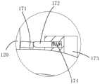
请结合图1和图4,在一实施例中,接线装置100还包括感应触头172和多个感应触点171。感应触点171设置于切换辊120并沿切换辊120的周向依次排布,且感应触点171与导体棒组件110一一对应。切换辊120带动感应触点171转动时,能够使多个感应触点171中的任一个与感应触头172相配合。当选定的感应触点171与感应触头172相配合时能够触发切换辊120停止转动,切换辊120停止转动时,该选定的感应触点171对应的导体棒组件110能够与多个第一导体相配合。Please refer to FIG. 1 and FIG. 4 , in an embodiment, the
具体地,感应触头172可通过固定杆173安装于安装箱140内,感应触头172与切换辊120的外周面相对设置。如图1所示,在本实施例中,感应触点171的数量为三个,在图1中沿顺时针方向依次为第一感应触点、第二感应触点、第三感应触点。三个感应触点171与三组导体棒组件110一一对应,第一感应触点对应于第一组导体棒111,第二感应触点对应于第二组导体棒111,第三感应触点对应于第三组导体棒111。三个感应触点171设置于切换辊120的外周面,并沿切换辊120的周向依次排布,从而切换辊120转动时能够带动感应触点171转动。通过将切换辊120转动不同的角度,则能够使不同的感应触点171与感应触头172配合。Specifically, the
具体地,如图1所示,可为控制装置164配置不同的功能开关165,并在控制装置164内设定不同的接线模式,并使功能开关165与接线模式一一对应。由于接线模式与导体棒组件110一一对应,导体棒组件110与感应触点171一一对应,因此,按压某个功能开关165时,则可在控制装置164内选定该功能开关165对应的接线模式。选定该功能开关165对应的接线模式时,则选定该接线模式对应的导体棒组件110和该导体棒组件110对应的感应触点171。Specifically, as shown in FIG. 1 , the
例如,接线装置100的某种接线模式对应于第三组导体棒组件110,在该接线模式下,第三组导体棒组件110与多个第一导体配合。若需要将接线装置100设定为该接线模式时,则可按压该接线模式对应的功能开关165。由于该接线模式对应于第三导体棒组件110,第三导体棒组件110对应于第三感应触头,因此,控制装置164则控制驱动机构161驱动切换辊120转动,以致切换辊120转动至第三感应触点与感应触头172相配合。第三感应触点与感应触头172相配合时,能够产生第三触发信号。控制装置164接收到该第三触发信号时,则控制驱动机构161停止驱动切换辊120,当切换辊120停止转动时,第三组导体棒组件110能够与多个第一导体相配合,从而则准确地将接线装置100切换至第三组导体棒组件110对应的该接线模式。For example, a certain wiring mode of the
同理,若需要将接线装置100切换至其他接线模式,则按压该其他接线模式对应的功能开关165,从而控制装置164能够控制切换辊120带动该其他接线模式对应的感应触点171与感应触头172配合。当该其他接线模式对应的感应触点171与感应触头172配合时,能够触发控制装置164控制切换辊120停止运动。当切换辊120停止转动时,该其他接线模式对应的导体棒组件110与第一导体相配合,则能够准确地将接线装置100切换至该其他接线模式。Similarly, if it is necessary to switch the
可以理解,在其他实施例中,也可不设定多个功能开关165,可通过其他方式选定不同的接线模式,例如可通过显示屏输入的方式。It can be understood that in other embodiments, multiple function switches 165 may not be set, and different wiring modes may be selected in other ways, such as inputting through a display screen.
在一实施例中,每个感应触点171分别与控制装置164的输出端连接,感应触头172与控制装置164的输入端连接。可通过另外配置的电路和控制装置164的配合,为不同的感应触点171输出不同的电压,且感应触点171与电压一一对应,从而,当不同的感应触点171与感应触头172配合时,控制装置164可接收到不同的电压信号。In one embodiment, each
按压某个功能开关165时,则选定该功能开关165对应的接线模式时,并选定该接线模式对应的导体棒组件110和该导体棒组件110对应的感应触点171,即选定该感应触点171对应的电压信号。When a
当控制装置164控制切换辊120转动至该感应触点171与感应触头172配合时,则控制装置164能够接收到该感应触点171对应的电压信号。当控制装置164接收到的电压信号与选定的电压信号相符合时,则控制装置164能够判断出选定的该感应触点171与感应触头172已经配合,从而控制装置164能够及时控制切换辊120停止运动,以致该感应触点171对应的导体棒组件110能够与第一导体配合,进而使得接线装置100准确地切换至该导体棒组件110对应的接线模式。When the
请结合图1和图4,在一实施例中,接线装置100还包括弹簧174。弹簧174的一端与固定杆173连接,另一端与感应触头172连接。感应触点171与感应触头172配合时,弹簧174的恢复力朝向感应触点171。Please refer to FIG. 1 and FIG. 4 , in an embodiment, the
具体地,由于感应触点171与感应触头172配合时,弹簧174的恢复力朝向感应触点171,从而弹簧174的恢复力能够使感应触点171与感应触头172抵接,进而使得感应触点171与感应触头172保持良好的电连接,有利于准确触发切换辊120停止运动。Specifically, when the
请参考图1,本申请另一实施例还提供一种测试装置10。测试装置10包括上述实施例中任一项的接线装置100和测试仪器11。每个导体棒111分别与各自对应的第二导线的一端电连接。第二导线的另一端与测试仪器11电连接,且第二导线与测试仪器11的接线端一一对应。Please refer to FIG. 1 , another embodiment of the present application also provides a
上述的测试装置10用于对电容电压互感器进行预防性试验项目测试时,将插头152插于二次端子箱。在需要进行某一种试验项目时,可通过转动切换辊120带动多组导体棒组件110转动,使得该试验项目对应的导体棒组件110与多个第一导体相配合,从而接线装置100能够切换至该试验项目对应的接线模式,且电容电压互感器的二次端子箱与测试仪器11能够电连接,接线方式迅速方便且能够准确切换至对应的接线模式。相比于传统的电容式电压互感器进行试验项目时的接线方式,使用本申请的测试装置10,不需要进行多次拆接线,从而不易造成接线错误,且能够节省人力和时间。并且仅需要一个插头152插入二次端子箱,不需要配置过多插头。The above-mentioned
以上实施例的各技术特征可以进行任意的组合,为使描述简洁,未对上述实施例中的各个技术特征所有可能的组合都进行描述,然而,只要这些技术特征的组合不存在矛盾,都应当认为是本说明书记载的范围。The technical features of the above embodiments can be combined arbitrarily. To make the description concise, all possible combinations of the technical features in the above embodiments are not described. However, as long as there is no contradiction in the combination of these technical features, they should be It is considered to be within the range described in this specification.
以上所述实施例仅表达了本发明的几种实施方式,其描述较为具体和详细,但并不能因此而理解为对本发明专利范围的限制。应当指出的是,对于本领域的普通技术人员来说,在不脱离本发明构思的前提下,还可以做出若干变形和改进,这些都属于本发明的保护范围。因此,本发明专利的保护范围应以所附权利要求为准。The above-mentioned embodiments only express several implementation modes of the present invention, and the descriptions thereof are relatively specific and detailed, but should not be construed as limiting the patent scope of the present invention. It should be pointed out that those skilled in the art can make several modifications and improvements without departing from the concept of the present invention, and these all belong to the protection scope of the present invention. Therefore, the protection scope of the patent for the present invention should be based on the appended claims.
Claims (10)
Priority Applications (1)
| Application Number | Priority Date | Filing Date | Title |
|---|---|---|---|
| CN202011337967.0ACN112710873B (en) | 2020-11-25 | 2020-11-25 | Wiring device and testing device |
Applications Claiming Priority (1)
| Application Number | Priority Date | Filing Date | Title |
|---|---|---|---|
| CN202011337967.0ACN112710873B (en) | 2020-11-25 | 2020-11-25 | Wiring device and testing device |
Publications (2)
| Publication Number | Publication Date |
|---|---|
| CN112710873A CN112710873A (en) | 2021-04-27 |
| CN112710873Btrue CN112710873B (en) | 2023-03-03 |
Family
ID=75542380
Family Applications (1)
| Application Number | Title | Priority Date | Filing Date |
|---|---|---|---|
| CN202011337967.0AActiveCN112710873B (en) | 2020-11-25 | 2020-11-25 | Wiring device and testing device |
Country Status (1)
| Country | Link |
|---|---|
| CN (1) | CN112710873B (en) |
Families Citing this family (2)
| Publication number | Priority date | Publication date | Assignee | Title |
|---|---|---|---|---|
| CN115173109A (en)* | 2022-08-23 | 2022-10-11 | 北京精仪达盛科技有限公司 | Wiring device and weak current experiment remote wiring system |
| CN116908499B (en)* | 2023-09-11 | 2023-12-05 | 山西天禄电力工程有限公司 | Junction device for electric power intelligent test |
Citations (7)
| Publication number | Priority date | Publication date | Assignee | Title |
|---|---|---|---|---|
| CN203054011U (en)* | 2012-12-09 | 2013-07-10 | 国家电网公司 | Wiring switch device for transformer winding deformation test |
| CN203849316U (en)* | 2014-05-27 | 2014-09-24 | 国家电网公司 | Multifunctional current signal sampling box used for relative dielectric loss and capacitance ratio measurement |
| CN106226564A (en)* | 2016-08-16 | 2016-12-14 | 国家电网公司 | High voltage capacitive-type voltage transformer without disconnecting power lead method routine test interconnecting device |
| CN106706970A (en)* | 2017-01-16 | 2017-05-24 | 国家电网公司 | Transformer direct-current resistance test connection switching box |
| CN206209037U (en)* | 2016-11-30 | 2017-05-31 | 山东久久星新能源车辆科技有限公司 | Electrical appliance kit detection means |
| CN111398644A (en)* | 2020-03-31 | 2020-07-10 | 贵州电网有限责任公司 | Mutual inductor handover test switching device and switching method thereof |
| CN211505705U (en)* | 2019-12-18 | 2020-09-15 | 中国长江电力股份有限公司 | CVT (continuously variable transmission) multi-item dielectric loss test system |
Family Cites Families (1)
| Publication number | Priority date | Publication date | Assignee | Title |
|---|---|---|---|---|
| US20200309840A1 (en)* | 2019-04-01 | 2020-10-01 | Dake He | Error Detection Wiring Circuit and Switching Device for Instrument Transformers in Distribution Power Grid |
- 2020
- 2020-11-25CNCN202011337967.0Apatent/CN112710873B/enactiveActive
Patent Citations (7)
| Publication number | Priority date | Publication date | Assignee | Title |
|---|---|---|---|---|
| CN203054011U (en)* | 2012-12-09 | 2013-07-10 | 国家电网公司 | Wiring switch device for transformer winding deformation test |
| CN203849316U (en)* | 2014-05-27 | 2014-09-24 | 国家电网公司 | Multifunctional current signal sampling box used for relative dielectric loss and capacitance ratio measurement |
| CN106226564A (en)* | 2016-08-16 | 2016-12-14 | 国家电网公司 | High voltage capacitive-type voltage transformer without disconnecting power lead method routine test interconnecting device |
| CN206209037U (en)* | 2016-11-30 | 2017-05-31 | 山东久久星新能源车辆科技有限公司 | Electrical appliance kit detection means |
| CN106706970A (en)* | 2017-01-16 | 2017-05-24 | 国家电网公司 | Transformer direct-current resistance test connection switching box |
| CN211505705U (en)* | 2019-12-18 | 2020-09-15 | 中国长江电力股份有限公司 | CVT (continuously variable transmission) multi-item dielectric loss test system |
| CN111398644A (en)* | 2020-03-31 | 2020-07-10 | 贵州电网有限责任公司 | Mutual inductor handover test switching device and switching method thereof |
Also Published As
| Publication number | Publication date |
|---|---|
| CN112710873A (en) | 2021-04-27 |
Similar Documents
| Publication | Publication Date | Title |
|---|---|---|
| TWI328684B (en) | Differential measurement probe having retractable double cushioned variable spacing probing tips and providing eos/esd protection | |
| CN112710873B (en) | Wiring device and testing device | |
| CN102272612B (en) | Testing apparatus | |
| CN105334352A (en) | Three-position switch array conduction insulation test device and method | |
| CN118465416B (en) | Surge protector reliability testing device and testing method | |
| JP3336525B2 (en) | Communication method | |
| CN115616440B (en) | Impedance measurement system | |
| CN113640694B (en) | Ripple noise test probe and test device | |
| CN211603378U (en) | Vehicle insulation resistance detection device | |
| CN113253017A (en) | Electrical performance test module of HDMI port | |
| US20200233042A1 (en) | Connector inspection instrument, connector set | |
| US2221556A (en) | Electrical connector apparatus | |
| CN113514780B (en) | A test system and test method for satellite low-frequency cables | |
| CN114487921A (en) | A terminal voltage detection device and a terminal fault detection method | |
| US3206707A (en) | Electronic circuit testing apparatus | |
| CN212459756U (en) | Electric connector test channel switching mechanism and adaptive converter | |
| CN115453202A (en) | A multi-circuit insulation resistance testing method | |
| CN115552736A (en) | A modular-based power distribution unit and power distribution system | |
| CN217954614U (en) | Direct-insertion type electrification detection device | |
| CN113391108A (en) | Plug-in type electric energy meter junction box and electric meter box | |
| CN210155230U (en) | Explosion-proof plug safety electricity testing device | |
| CN223139759U (en) | A dielectric withstand test tool for SMP type RF cable components | |
| CN111812364A (en) | Metering junction box | |
| CN114325345B (en) | Burn-in machine and interface board for burn-in machine | |
| CN219456225U (en) | Jumper device and battery test system for vehicle power battery test |
Legal Events
| Date | Code | Title | Description |
|---|---|---|---|
| PB01 | Publication | ||
| PB01 | Publication | ||
| SE01 | Entry into force of request for substantive examination | ||
| SE01 | Entry into force of request for substantive examination | ||
| GR01 | Patent grant | ||
| GR01 | Patent grant |