CN112702330B - Lightweight in-band network telemetry method, device and storage medium for overlay network - Google Patents
Lightweight in-band network telemetry method, device and storage medium for overlay networkDownload PDFInfo
- Publication number
- CN112702330B CN112702330BCN202011515170.5ACN202011515170ACN112702330BCN 112702330 BCN112702330 BCN 112702330BCN 202011515170 ACN202011515170 ACN 202011515170ACN 112702330 BCN112702330 BCN 112702330B
- Authority
- CN
- China
- Prior art keywords
- network
- detection
- path
- int
- packet
- Prior art date
- Legal status (The legal status is an assumption and is not a legal conclusion. Google has not performed a legal analysis and makes no representation as to the accuracy of the status listed.)
- Active
Links
Images


Classifications
- H—ELECTRICITY
- H04—ELECTRIC COMMUNICATION TECHNIQUE
- H04L—TRANSMISSION OF DIGITAL INFORMATION, e.g. TELEGRAPHIC COMMUNICATION
- H04L69/00—Network arrangements, protocols or services independent of the application payload and not provided for in the other groups of this subclass
- H04L69/22—Parsing or analysis of headers
- G—PHYSICS
- G06—COMPUTING OR CALCULATING; COUNTING
- G06F—ELECTRIC DIGITAL DATA PROCESSING
- G06F9/00—Arrangements for program control, e.g. control units
- G06F9/06—Arrangements for program control, e.g. control units using stored programs, i.e. using an internal store of processing equipment to receive or retain programs
- G06F9/44—Arrangements for executing specific programs
- G06F9/455—Emulation; Interpretation; Software simulation, e.g. virtualisation or emulation of application or operating system execution engines
- G06F9/45533—Hypervisors; Virtual machine monitors
- G06F9/45558—Hypervisor-specific management and integration aspects
- H—ELECTRICITY
- H04—ELECTRIC COMMUNICATION TECHNIQUE
- H04L—TRANSMISSION OF DIGITAL INFORMATION, e.g. TELEGRAPHIC COMMUNICATION
- H04L41/00—Arrangements for maintenance, administration or management of data switching networks, e.g. of packet switching networks
- H04L41/06—Management of faults, events, alarms or notifications
- H04L41/0677—Localisation of faults
- H—ELECTRICITY
- H04—ELECTRIC COMMUNICATION TECHNIQUE
- H04L—TRANSMISSION OF DIGITAL INFORMATION, e.g. TELEGRAPHIC COMMUNICATION
- H04L43/00—Arrangements for monitoring or testing data switching networks
- H04L43/08—Monitoring or testing based on specific metrics, e.g. QoS, energy consumption or environmental parameters
- H—ELECTRICITY
- H04—ELECTRIC COMMUNICATION TECHNIQUE
- H04L—TRANSMISSION OF DIGITAL INFORMATION, e.g. TELEGRAPHIC COMMUNICATION
- H04L45/00—Routing or path finding of packets in data switching networks
- H04L45/54—Organization of routing tables
- H—ELECTRICITY
- H04—ELECTRIC COMMUNICATION TECHNIQUE
- H04L—TRANSMISSION OF DIGITAL INFORMATION, e.g. TELEGRAPHIC COMMUNICATION
- H04L45/00—Routing or path finding of packets in data switching networks
- H04L45/74—Address processing for routing
- H04L45/745—Address table lookup; Address filtering
- G—PHYSICS
- G06—COMPUTING OR CALCULATING; COUNTING
- G06F—ELECTRIC DIGITAL DATA PROCESSING
- G06F9/00—Arrangements for program control, e.g. control units
- G06F9/06—Arrangements for program control, e.g. control units using stored programs, i.e. using an internal store of processing equipment to receive or retain programs
- G06F9/44—Arrangements for executing specific programs
- G06F9/455—Emulation; Interpretation; Software simulation, e.g. virtualisation or emulation of application or operating system execution engines
- G06F9/45533—Hypervisors; Virtual machine monitors
- G06F9/45558—Hypervisor-specific management and integration aspects
- G06F2009/45579—I/O management, e.g. providing access to device drivers or storage
- G—PHYSICS
- G06—COMPUTING OR CALCULATING; COUNTING
- G06F—ELECTRIC DIGITAL DATA PROCESSING
- G06F9/00—Arrangements for program control, e.g. control units
- G06F9/06—Arrangements for program control, e.g. control units using stored programs, i.e. using an internal store of processing equipment to receive or retain programs
- G06F9/44—Arrangements for executing specific programs
- G06F9/455—Emulation; Interpretation; Software simulation, e.g. virtualisation or emulation of application or operating system execution engines
- G06F9/45533—Hypervisors; Virtual machine monitors
- G06F9/45558—Hypervisor-specific management and integration aspects
- G06F2009/45595—Network integration; Enabling network access in virtual machine instances
- H—ELECTRICITY
- H04—ELECTRIC COMMUNICATION TECHNIQUE
- H04L—TRANSMISSION OF DIGITAL INFORMATION, e.g. TELEGRAPHIC COMMUNICATION
- H04L2212/00—Encapsulation of packets
Landscapes
- Engineering & Computer Science (AREA)
- Computer Networks & Wireless Communication (AREA)
- Signal Processing (AREA)
- Software Systems (AREA)
- Theoretical Computer Science (AREA)
- Physics & Mathematics (AREA)
- General Engineering & Computer Science (AREA)
- General Physics & Mathematics (AREA)
- Computer Security & Cryptography (AREA)
- Environmental & Geological Engineering (AREA)
- Data Exchanges In Wide-Area Networks (AREA)
Abstract
Translated fromChinese
Description
Translated fromChinese技术领域technical field
本发明属于通讯领域,更具体地说,涉及一种面向Overlay网络的轻量级带内网络遥测方法、装置及存储介质。The invention belongs to the field of communications, and more particularly, relates to a lightweight in-band network telemetry method, device and storage medium oriented to an Overlay network.
背景技术Background technique
随着云计算在数据中心和企业网络中的广泛应用,云服务模式成为重要的服务模式。虚拟化技术作为云计算的显著特征,可以有效提高资源利用率,降低数据中心的运维成本。然而,虚拟机数量增多以及虚拟机频繁动态迁移所带来的问题也随之出现,传统网络已经无法很好地满足虚拟机在任意网络位置之间无感知迁移的需求,因此,Overlay网络方案应运而生。With the widespread application of cloud computing in data centers and enterprise networks, the cloud service model has become an important service model. As a significant feature of cloud computing, virtualization technology can effectively improve resource utilization and reduce data center operation and maintenance costs. However, the problems caused by the increase in the number of virtual machines and the frequent dynamic migration of virtual machines also appear. Traditional networks can no longer meet the needs of non-aware migration of virtual machines between any network location. Therefore, the overlay network solution should be used as the times require. and live.
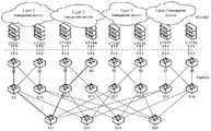
Overlay在网络技术领域,指的是一种网络架构上叠加的虚拟化技术模式,其大体框架是对基础网络不进行大规模修改的条件下,实现应用在网络上的承载,并能与其它网络业务分离,并且以基于IP的基础网络技术为主。Overlay技术是在现有的物理网络之上构建一个虚拟网络,上层应用只与虚拟网络相关。与之对应的传统网络,一般称之为Underlay网络。 Overlay网络在不改变原始架构的基础上为各类云业务提供支撑,可以在基础物理网络上运行多个单独离散化虚拟网络,它们具有独立的控制平面和数据平面。如图1所示,从物理角度看,Overlay网络非常复杂,任意两个节点之间可能存在多种转发路径或物理链路;从Overlay 网络中的终端主机角度看,网络通信过程简洁,底层Underlay网络是透明不可见的,具有大二层透明服务机制(Layer 2Transparent Service)。虚拟扩展局域网(Virtual eXtensible Local Area Network,VXLAN)技术作为网络虚拟化的通用隧道协议,是Overlay网络领域的重要技术方案,大多数软件虚拟交换机和硬件设备都支持VXLAN实现。VXLAN网络搭建了 VXLAN隧道进行通信,通信虚拟机或服务器双方通过VXLAN隧道进行交互。VXLAN隧道终点(VXLAN Tunnel End Point,VTEP)部署在VXLAN网络边缘,负责连接租户网络与 VXLAN网络,进行报文的封装和解封装,屏蔽了虚拟机对Underlay网络的感知。VXLAN 作为虚拟网络技术,运行在现有网络基础架构之上,将二层网络在三层范围进行扩展,增加了租户数量,实现了虚拟网络的灵活扩展部署,扩大了虚拟机迁移范围,更好地满足数据中心部署大二层网络的需求。与此同时,数据中心Overlay网络的不断发展使得网络复杂性也在不断增加,运维难度增大,网络检测更加困难。数据中心网络的实时准确的监测,有利于发现网络瓶颈,优化网络配置,定位潜在危险,进行有效的网络性能管理等。带内网络遥测 (In-band Network Telemetry,INT)技术作为一种细粒度网络监测的新型遥测协议,由Barefoot, Arista,Dell,Intel和VMware联合提出,具有复杂而灵活的遥测机制。INT使用镜像报文,通过采样方式采集镜像,仅占少部分的带宽。INT模型的时间信息精度高,精确到微秒,不存在时钟偏差。INT在数据层面收集和报告网络状态,整个过程不需要控制层面参与,不会增加网络设备CPU的负担。In the field of network technology, overlay refers to a virtualization technology model that is superimposed on the network architecture. The business is separated, and the basic network technology based on IP is mainly used. Overlay technology builds a virtual network on top of the existing physical network, and the upper-layer application is only related to the virtual network. The corresponding traditional network is generally called the Underlay network. The overlay network provides support for various cloud services without changing the original architecture, and can run multiple separate discrete virtual networks on the basic physical network, which have independent control planes and data planes. As shown in Figure 1, from the physical point of view, the overlay network is very complex, and there may be multiple forwarding paths or physical links between any two nodes; from the perspective of the terminal host in the overlay network, the network communication process is simple, and the underlying Underlay The network is transparent and invisible, and has a
然而,除了VTEP能够感知隧道底层网络设备的存在外,其他终端服务器等无法感知到 Overlay网络覆盖下Underlay网络及其链路,INT作为一种基础原语,只基于底层网络定义了传入的探测数据包与设备内部状态之间的简单交互方式,没有进行高级设置。同时,Overlay 网络中任意终端设备进行相互通信时,网络中的某些节点处会存在重复的数据包,换言之,监测系统中存在大量重复探测路径。最坏情况下,N个主机或服务器相互通信时,整个网络中存在N2条Overlay链路,从而导致了“N平方”问题。每条链路可能经过相同的底层设备路径,即同一条Underlay链路上的状态信息被多条Overlay链路重复采集,增加了监测系统的网络开销。如图1所示,当VTEP1连接的虚拟机与VTEP3连接的虚拟机进行通信时,探测数据包在对应Underlay网络中的转发路径为[S1,S9,S17,S11,S3];当VTEP1连接的虚拟机与VTEP4连接的虚拟机进行通信时,探测包在对应底层网络中的转发路径为[S1,S9,S17,S11,S4]。显然,此时存在重复探测路径[S1,S9,S17,S11]。这不仅会给控制器带来性能负担,而且会占用有限的链路带宽,从而导致较高的遥测开销。因此,Overlay网络监测的实现需要对探测路径进行合理的规划,并需要更高层的INT设计。因此,如何利用INT技术构建轻量级的Overlay网络监测系统、实现数据中心网络流量的监控和管理、进行探测路径的有效规划、以更低开销获取网络链路设备的监测信息,成为亟待解决的技术挑战。However, in addition to VTEP being able to perceive the existence of the tunnel underlying network equipment, other terminal servers cannot perceive the Underlay network and its links covered by the Overlay network. INT, as a basic primitive, only defines incoming probes based on the underlying network. Simple interaction between packets and device internal state, no advanced settings. At the same time, when any terminal device in the overlay network communicates with each other, there will be duplicate data packets at some nodes in the network, in other words, there are a large number of duplicate detection paths in the monitoring system. In the worst case, when N hosts or servers communicate with each other, there are N2 overlay links in the entire network, which leads to the "N squared" problem. Each link may pass through the same underlying device path, that is, the status information on the same Underlay link is collected repeatedly by multiple Overlay links, which increases the network overhead of the monitoring system. As shown in Figure 1, when the virtual machine connected to VTEP1 communicates with the virtual machine connected to VTEP3, the forwarding path of the detection packet in the corresponding Underlay network is [S1, S9, S17, S11, S3]; When the virtual machine communicates with the virtual machine connected to VTEP4, the forwarding path of the probe packet in the corresponding underlying network is [S1, S9, S17, S11, S4]. Obviously, there are duplicate detection paths [S1, S9, S17, S11] at this time. This not only imposes a performance burden on the controller, but also consumes limited link bandwidth, resulting in high telemetry overhead. Therefore, the realization of Overlay network monitoring requires reasonable planning of the detection path and requires higher-level INT design. Therefore, how to use INT technology to build a lightweight overlay network monitoring system, realize the monitoring and management of data center network traffic, perform effective planning of detection paths, and obtain monitoring information of network link devices at a lower cost has become an urgent problem to be solved. technical challenges.
VXLAN是Overlay网络的重要实现技术之一,它是一种隧道模式的网络覆盖技术。VXLAN网络模型整体架构如图2所示,VXLAN网络标识符(VXLAN Network Identifier, VNI)和其它相关封装信息只有VTEP可见,具有相同VNI的虚拟机(VM)可以进行相互通信;只有隧道端点VTEP能够感知VNI和隧道底层网络设备的存在,对于终端虚拟机而言,上述设备是透明的。VXLAN采用“MAC in UDP”的报文封装模式,如图3所示,添加外部以太首部(Outer MACHeader)和外部IP首部(Outer IP Header),将原始以太网报文和VXLAN 首部封装成UDP报文进行隧道传输。VXLAN等Overlay网络应用较好地满足了数据中心规模扩大、虚拟机灵活迁移和租户隔离的需求。VXLAN is one of the important implementation technologies of overlay network. It is a network overlay technology in tunnel mode. The overall architecture of the VXLAN network model is shown in Figure 2. The VXLAN Network Identifier (VNI) and other related encapsulation information are only visible to VTEP, and virtual machines (VMs) with the same VNI can communicate with each other; only the tunnel endpoint VTEP can Perceiving the existence of VNI and tunnel underlying network devices, the above devices are transparent to terminal virtual machines. VXLAN adopts the packet encapsulation mode of "MAC in UDP", as shown in Figure 3, adding an outer Ethernet header (Outer MACHeader) and an outer IP header (Outer IP Header), and encapsulates the original Ethernet packet and VXLAN header into a UDP packet. The file is tunneled. Overlay network applications such as VXLAN can better meet the needs of data center scale expansion, flexible virtual machine migration, and tenant isolation.
Overlay网络共享相同的底层Underlay网络,由于封装机制和虚拟隧道方案,用户和业务感知不到底层网络中的转发路径和链路设备,这对于用户而言通信过程更加简洁,但是不利于网络运维和监测。Overlay网段两端虚拟机无法看到虚线下对应的网络拓扑,不能获知 VXLAN的实现细节以及通信过程。当数据包转发到终端主机或服务器时,其中携带的遥测信息已被VTEP剥离并丢弃,无法传送到控制器或其他设备进行后续处理。因此,典型的监控工具难以直接对Overlay网络进行监测。此外,底层的Underlay网络拓扑之上对应多个不同的Overlay网络,Overlay网络也是高度动态的,Overlay网络的复杂性同样增大了监测难度。Overlay networks share the same underlying Underlay network. Due to the encapsulation mechanism and virtual tunnel scheme, users and services cannot perceive forwarding paths and link devices in the underlying network. This makes the communication process simpler for users, but is not conducive to network operation and maintenance. and monitoring. The virtual machines at both ends of the overlay network segment cannot see the corresponding network topology under the dotted line, and cannot learn the implementation details and communication process of VXLAN. When the data packet is forwarded to the end host or server, the telemetry information carried in it has been stripped and discarded by the VTEP, and cannot be transmitted to the controller or other devices for subsequent processing. Therefore, it is difficult for typical monitoring tools to directly monitor the overlay network. In addition, the underlying Underlay network topology corresponds to multiple different Overlay networks. The Overlay network is also highly dynamic. The complexity of the Overlay network also increases the difficulty of monitoring.
基于P4编程语言的INT(P4-based INT)技术是最早的带内网络遥测实现方案。INT可以借助P4可编程网络芯片任意修改数据报文包头字段,将网络信息元数据嵌入到每个探测包中,并携带到远端的控制器上进行进一步的分析;整个过程除了最后一跳信息上送,均在高速数据平面完成,不改变原始业务报文的转发路径。P4-based INT包括三类实体:INT源端, INT传输设备和INT终端。INT源端是遥测路线的起点,负责将遥测指令嵌入到正常数据包或遥测数据包中;INT传输设备是具有INT功能的网络中间设备,能够解析遥测指令,并向数据包中插入INT元信息;INT终端是遥测路线的终点,负责对遥测结果进行提取和上报。INT源端和INT终端可以是应用、网管程序、发送侧/接收侧柜顶(Top of Rank,ToR)交换机等。这种测量方式不仅能采集每跳网络节点上的多种内部状态信息,而且无需频繁与控制平面发生交互,整体的测量时延大大降低。The INT (P4-based INT) technology based on the P4 programming language is the earliest implementation of in-band network telemetry. INT can arbitrarily modify the header field of the data packet with the help of the P4 programmable network chip, embed the network information metadata into each probe packet, and carry it to the remote controller for further analysis; the whole process except the last hop information The forwarding is completed on the high-speed data plane, and the forwarding path of the original service packet is not changed. P4-based INT includes three types of entities: INT source, INT transmission device and INT terminal. The INT source is the starting point of the telemetry route and is responsible for embedding telemetry commands into normal data packets or telemetry data packets; the INT transmission device is a network intermediate device with INT function, which can parse the telemetry commands and insert INT meta-information into the data packets ; The INT terminal is the end point of the telemetry route and is responsible for extracting and reporting the telemetry results. The INT source end and the INT terminal may be applications, network management programs, top of rack (Top of Rank, ToR) switches on the sending side/receiving side, and the like. This measurement method can not only collect a variety of internal state information on each hop network node, but also does not need to interact with the control plane frequently, and the overall measurement delay is greatly reduced.
INT技术仅基于协议无关的转发体系结构定义了遥测报文格式和在每个设备上搜集信息的方式,尚未解决如何实现Overlay网络的流量监视以及遥测路径规划等问题。INT操作将采集到的设备信息插入到探测包之中,会占用一部分链路带宽,并且遥测系统中存在大量带有探测数据包的监视路径,导致了较大的网络开销。一方面,INT执行时,转发路径中的每个设备都会在INT数据包中创建额外的空间以添加自己的INT元数据;另一方面,Overlay网络的遥测系统中往往存在许多重复的INT探测路径,增加了遥测开销。The INT technology only defines the telemetry packet format and the method of collecting information on each device based on the protocol-independent forwarding architecture, and has not yet solved the problems of how to implement the traffic monitoring of the overlay network and the telemetry path planning. The INT operation inserts the collected device information into the probe packet, which will occupy a part of the link bandwidth, and there are a large number of monitoring paths with probe packets in the telemetry system, resulting in a large network overhead. On the one hand, when INT is executed, each device in the forwarding path creates extra space in the INT packet to add its own INT metadata; on the other hand, there are often many duplicate INT detection paths in the telemetry system of the Overlay network , which increases the telemetry overhead.
PingMesh是微软应用于Azure数据中心的全量Ping测试技术,主要由PingMesh控制器、 PingMesh代理、数据存储与分析三部分构成。PingMesh能够在Overlay网络的任意两个服务器之间运行Ping测试,获得任何时刻的网络延时,可视化地去显示任意两个端点之间的连接状况。PingMesh is a full-scale Ping test technology used by Microsoft in the Azure data center. It is mainly composed of three parts: PingMesh controller, PingMesh agent, data storage and analysis. PingMesh can run the Ping test between any two servers in the Overlay network, obtain the network delay at any time, and visually display the connection status between any two endpoints.
PingMesh技术通过端侧发起的Ping包进行端到端网络拥塞检测,只能探测到整条链路端到端的时延情况,无法解决逐跳(Hop-by-hop)探测问题,即探测不到路由器或交换机等网络设备侧的逐跳时延,无法进一步挖掘网络设备内部状态信息。PingMesh技术虽然能够检测 Overlay网络中线故障网络,但是无法获知具体位置,而良好的故障排除需要获知传输路径,需要更加细粒化的网络可见性。PingMesh technology performs end-to-end network congestion detection through Ping packets initiated by the end-side. It can only detect the end-to-end delay of the entire link, and cannot solve the hop-by-hop detection problem, that is, it cannot detect The hop-by-hop delay on the network device side such as routers or switches cannot further mine the internal state information of network devices. Although PingMesh technology can detect the faulty network in the center line of the overlay network, it cannot know the specific location, and good troubleshooting needs to know the transmission path and more fine-grained network visibility.
发明内容SUMMARY OF THE INVENTION
1.要解决的问题1. The problem to be solved
针对现有技术中存在的INT技术构建的Overlay网络监测系统无法实现数据中心网络流量的监控和管理、进行探测路径的有效规划、以更低开销获取网络链路设备的监测信息的问题,本发明提出了一种面向Overlay网络的轻量级带内网络遥测方法、装置和存储介质,实现了Overlay网络链路中设备状态信息的准确采集与监测;进一步地,此方法在Overlay网络中结合路径规划策略,用更少的路径覆盖全网进行遥测,结合提出的“两路探测”和“两步查找”策略,在实现Overlay网络有效监测的同时降低了网络监测开销;另外,本发明提出的轻量级网络监测方法有助于脱离Overlay网络的监控困境,实现低开销的网络监测功能。Aiming at the problem that the overlay network monitoring system constructed by the INT technology in the prior art cannot realize the monitoring and management of the network traffic of the data center, effectively plan the detection path, and obtain the monitoring information of the network link equipment with a lower cost, the present invention A lightweight in-band network telemetry method, device and storage medium for overlay network are proposed, which realizes accurate collection and monitoring of device status information in overlay network links; further, this method combines path planning in overlay network strategy, using fewer paths to cover the entire network for telemetry, combined with the proposed "two-way detection" and "two-step search" strategy, to achieve effective monitoring of the Overlay network and reduce network monitoring overhead; The magnitude-scale network monitoring method helps to get rid of the monitoring dilemma of the overlay network and realize the low-cost network monitoring function.
2.技术方案2. Technical solutions
为了解决上述问题,本发明所采用的技术方案如下:一种面向Overlay网络的轻量级带内网络遥测方法,包括以下步骤:In order to solve the above problems, the technical solution adopted in the present invention is as follows: a lightweight in-band network telemetry method oriented to the Overlay network, comprising the following steps:
S1、对IP报文进行封装以得到探测数据包,使探测数据包能够依次采集沿途Underlay 设备的ID以及设备端口侧的链路状态信息;S1. Encapsulate the IP packet to obtain the probe data packet, so that the probe data packet can sequentially collect the ID of the Underlay device along the way and the link status information on the device port side;
S2、对探测数据包进行解析;S2, analyze the detection data packet;
S3、以Overlay网络中的任一设备为根节点开始遍历,得到非重叠的探测路径;S3. Start the traversal with any device in the Overlay network as the root node to obtain a non-overlapping detection path;
S4、依据步骤S3中的探测路径进行控制,得到定制的探测数据包转发路径;S4, control according to the detection path in step S3 to obtain a customized detection packet forwarding path;
S5、当探测数据包到达终点后,将采集到的网络监测信息进行存储和查询。S5. After the detection data packet reaches the end point, the collected network monitoring information is stored and queried.
本技术方案通过对IP报文进行封装,以便采集沿途Underlay设备的ID以及设备端口侧的链路状态信息,然后以Overlay网络中的任一设备为根节点开始遍历,得到非重叠的探测路径,并依据探测路径进行控制得到定制的探测数据包转发路径,对采集的网络监测信息进行存储和查询,在数据层面上指定探测数据包的转发路由,实现路径控制功能和细粒度网络遥测功能,完成链路设备侧状态信息的采集,从而以更低开销实现了轻量级的Overlay网络监测。This technical solution encapsulates IP packets so as to collect the IDs of the Underlay devices along the way and the link status information on the port side of the devices, and then starts the traversal with any device in the Overlay network as the root node to obtain non-overlapping detection paths. And according to the detection path, the customized detection data packet forwarding path is obtained by control, the collected network monitoring information is stored and queried, the forwarding route of the detection data packet is specified at the data level, and the path control function and fine-grained network telemetry function are realized. The collection of status information on the link device side realizes lightweight overlay network monitoring with lower overhead.
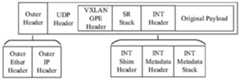
进一步地,在所述探测数据包的原始报文外部依次添加INT首部、SR标签栈、VXLAN首部、UDP首部、外部IP首部和外部Ether首部,以构成用于Overlay网络信息采集的探测数据包。Further, an INT header, an SR label stack, a VXLAN header, a UDP header, an external IP header, and an external Ether header are sequentially added outside the original message of the detection data packet to form a detection data packet for Overlay network information collection.
进一步地,所述INT首部包括INT Shim Header、INT Metadata和INT MetadataStack。Further, the INT header includes INT Shim Header, INT Metadata and INT MetadataStack.
进一步地,所述步骤S2具体为:先通过匹配Ether首部中的以太网类型字段、IP报文中的封装协议字段和UDP报文的目标端口字段对数据包进行初步解析,然后对VXLAN报文、 SR报文和INT报文进行解析。Further, described step S2 is specifically: first by matching the Ethernet type field in the Ether header, the encapsulation protocol field in the IP message and the target port field of the UDP message, the data packet is initially analyzed, and then the VXLAN message is analyzed. , SR packets, and INT packets for parsing.
进一步地,所述步骤S4具体为:通过指定每个设备的输出端口来指引探测数据包有目的性地转发,从而得到定制的探测数据包转发路径。本技术方案通过对每个设备的输出端口进行指定,来指引探测数据包有目的的转发,从而定制每条探测路径的走向,解决了Overlay 网络传输路径不可见的问题。Further, the step S4 is specifically: by specifying the output port of each device to guide the forwarding of the detection data packet in a purposeful manner, thereby obtaining a customized forwarding path of the detection data packet. The technical solution guides the purposeful forwarding of detection data packets by specifying the output port of each device, thereby customizing the direction of each detection path, and solving the problem that the transmission path of the overlay network is invisible.
进一步地,所述步骤S3中采用的路径探测方法为深度优先遍历算法。本技术方案采用深度优先遍历算法实现有效的探测路径规划机制,在不影响遥测性能的前提下,使用更少的探测路径进行全网监测,克服了Overlay网络中用户进行通信时造成的大量重复探测路径问题,降低了网络监测开销。Further, the path detection method adopted in the step S3 is a depth-first traversal algorithm. The technical solution adopts the depth-first traversal algorithm to realize an effective detection path planning mechanism. On the premise of not affecting the telemetry performance, it uses fewer detection paths to monitor the whole network, and overcomes a large number of repeated detections caused by users in the overlay network when they communicate. Path problems, reducing network monitoring overhead.
进一步地,所述步骤S5中的网络监测信息存储具体为:控制层依据两路探测的检测方式存储数据层获取的网络监测信息,其中一路为按照深度优先遍历算法和SR机制规划的路径进行全网随路检测,数据包在转发过程中沿路依次采集Underlay网络设备的内部状态信息;第二路为当Overlay网络中任意主机之间进行通信时,数据包只采集Underlay网络设备的ID。Further, the storage of the network monitoring information in the step S5 is specifically: the control layer stores the network monitoring information obtained by the data layer according to the detection methods of the two-way detection, and one of them is the path planned according to the depth-first traversal algorithm and the SR mechanism. In the network-based detection, the internal status information of the Underlay network device is sequentially collected along the way of the data packet during the forwarding process; the second way is when any host in the Overlay network communicates, the data packet only collects the ID of the Underlay network device.
进一步地,所述步骤S5中的网络监测信息查询具体为:Further, the network monitoring information query in the step S5 is specifically:
S51、通过两端设备的Overlay隧道信息查询Underlay经过的有序设备ID;S51 , query the ordered device IDs passed by the Underlay through the Overlay tunnel information of the devices at both ends;
S52、通过步骤S51查询所得的有序设备ID序列进一步查询每个设备的端口链路状态信息。本技术方案可以迅速发现链路中异常数据的具体位置,从而实现准确的故障定位。S52, further query the port link status information of each device through the ordered device ID sequence obtained by the query in step S51. The technical solution can quickly find the specific location of abnormal data in the link, thereby realizing accurate fault location.
本发明同时还提供一种面向Overlay网络的轻量级带内网络遥测装置,包括报文封装模块、报文解析模块、探测路径生成模块、探测路径定制模块、探测信息存储模块和探测信息查询模块,所述报文封装模块用于对IP报文进行封装,以得到探测数据包,所述探测数据包能够依次采集沿途Underlay设备的ID以及设备端口侧的链路状态信息;所述报文解析模块用于对探测数据包进行解析;所述探测路径生成模块用于生成非重叠的探测路径;所述探测路径定制模块用于通过指定交换机的输出端口来指引探测数据包有目的性地转发,从而得到定制的探测路径;所述探测信息存储模块用于存储采集到的网络监测信息;所述探测信息查询模块用于获取监测到的设备状态信息。The present invention also provides a lightweight in-band network telemetry device for overlay network, including a message encapsulation module, a message parsing module, a detection path generation module, a detection path customization module, a detection information storage module and a detection information query module , the message encapsulation module is used to encapsulate the IP message to obtain a probe data packet, which can sequentially collect the ID of the Underlay device along the way and the link status information on the port side of the device; the packet analysis The module is used to parse the detection data packets; the detection path generation module is used to generate non-overlapping detection paths; the detection path customization module is used to guide the detection data packets to be forwarded purposefully by specifying the output port of the switch, Thereby, a customized detection path is obtained; the detection information storage module is used to store the collected network monitoring information; the detection information query module is used to obtain the monitored device state information.
本发明还提供一种计算机可读存储介质,所述计算机可读存储介质存储有计算机指令,所述计算机指令用于使所述计算机执行上述的面向Overlay网络的轻量级带内网络遥测方法。The present invention also provides a computer-readable storage medium, where the computer-readable storage medium stores computer instructions, and the computer instructions are used to cause the computer to execute the above-mentioned lightweight in-band network telemetry method for an overlay network.
3.有益效果3. Beneficial effects
相比于现有技术,本发明的有益效果为:Compared with the prior art, the beneficial effects of the present invention are:
(1)本发明基于P4语言定义了数据报文格式、设计了高级解析过程,基于DFS路径生成算法和SR路径控制策略提出了有效的探测路径规划机制,在不影响遥测性能的前提下,通过两路探测策略,使用更少的探测路径进行全网监测,克服了Overlay网络中用户进行通信时造成的大量重复探测路径问题,降低了网络监测开销、全网探测路径和控制器的储存消耗,实现了轻量级的带内网络遥测;(1) The present invention defines the data packet format based on the P4 language, designs an advanced parsing process, and proposes an effective detection path planning mechanism based on the DFS path generation algorithm and the SR path control strategy. The two-way detection strategy uses fewer detection paths to monitor the entire network, overcomes the problem of a large number of repeated detection paths caused by users in the overlay network when communicating, and reduces network monitoring overhead, network-wide detection paths, and storage consumption of the controller. Implemented lightweight in-band network telemetry;
(2)本发明提出的面向Overlay网络的轻量级带内网络遥测方法,能够在Overlay网络通信过程中,依次采集对应底层网络转发路径的设备ID信息,准确获取Overlay网络与Underlay网络的映射关系。利用通信两端的虚拟机ID或IP,通过查询INT探测路径表,即可快速获取对应底层链路的交换机设备ID,从而确定传输路径。本发明克服了Overlay网络底层链路的透明特性,解决了Overlay网络传输路径不可见问题,可迅速发现异常数据的具体位置,从而实现准确的故障定位;(2) The lightweight in-band network telemetry method for the overlay network proposed by the present invention can sequentially collect the device ID information corresponding to the underlying network forwarding path during the overlay network communication process, and accurately obtain the mapping relationship between the overlay network and the underlay network . Using the virtual machine ID or IP at both ends of the communication, by querying the INT detection path table, the switch device ID corresponding to the underlying link can be quickly obtained, thereby determining the transmission path. The invention overcomes the transparent characteristic of the underlying link of the Overlay network, solves the problem of the invisible transmission path of the Overlay network, and can quickly find the specific location of abnormal data, thereby realizing accurate fault location;
(3)本发明通Overlay网络监测方法,利用INT探测数据包处理隧道流量,随路测量并采集单跳网络设备侧的状态信息,在探测数据包中依次嵌入沿途INT元信息,同时结合主机通信时获取的路径信息,控制器可以通过两步查找操作,获取端到端链路的逐跳遥测信息,例如交换机出入端口ID、排队时延和处理时延等,解决了Overlay网络的监测难题,能够根据路径信息迅速获取对应Underlay链路的设备级状态信息。(3) The present invention uses the INT detection data packet to process the tunnel traffic through the overlay network monitoring method, measures and collects the status information of the single-hop network device side along the road, and sequentially embeds the INT meta-information along the route in the detection data packet, and combines the host communication at the same time. The controller can obtain the hop-by-hop telemetry information of the end-to-end link through a two-step search operation, such as the switch’s ingress and egress port ID, queuing delay and processing delay, etc., which solves the monitoring problem of the overlay network. The device-level status information corresponding to the Underlay link can be quickly obtained according to the path information.
附图说明Description of drawings
图1为现有技术中底层Underlay网络与Overlay网络的示意图;1 is a schematic diagram of a bottom layer Underlay network and an Overlay network in the prior art;
图2为现有技术中VXLAN网络模型示意图;2 is a schematic diagram of a VXLAN network model in the prior art;
图3为现有技术中VXLAN报文格式;Fig. 3 is the VXLAN message format in the prior art;
图4为本发明中探测数据包的报文格式;Fig. 4 is the message format of the detection data packet in the present invention;
图5为本发明中VXLAN_GPE首部封装格式;Fig. 5 is the VXLAN_GPE header encapsulation format in the present invention;
图6为本发明中SR报文封装格式;Fig. 6 is the SR message encapsulation format in the present invention;
图7为本发明中用于VXLAN GPE封装的INT首部;Fig. 7 is the INT header for VXLAN GPE encapsulation in the present invention;
图8为本发明中数据报文解析图;Fig. 8 is a data message analysis diagram in the present invention;
图9为本发明中部分报文解析代码;Fig. 9 is part of the message parsing code in the present invention;
图10为本发明中深度优先遍历图;10 is a depth-first traversal diagram in the present invention;
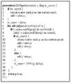
图11为本发明中DFS路径生成算法伪代码;Fig. 11 is DFS path generation algorithm pseudo code in the present invention;
图12为本发明中Overlay网络中INT探测包路径转发和信息采集流程图;12 is a flowchart of INT detection packet path forwarding and information collection in the Overlay network in the present invention;
图13为本发明中Fat-Tree网络拓扑图;Fig. 13 is Fat-Tree network topology diagram in the present invention;
图14(a)为本发明中路径规划前后的INT探测信息(排队时延);Figure 14(a) is the INT detection information (queuing delay) before and after path planning in the present invention;
图14(b)为本发明中路径规划前后的INT探测信息(处理时延);Figure 14(b) is the INT detection information (processing delay) before and after path planning in the present invention;
图15为本发明中INT监测信息查询过程示意图;Figure 15 is a schematic diagram of an INT monitoring information query process in the present invention;
图16(a)为网络监测系统中路径规划前的网络开销;Figure 16(a) shows the network overhead before path planning in the network monitoring system;
图16(b)为网络监测系统中路径规划后的网络开销。Figure 16(b) shows the network overhead after path planning in the network monitoring system.
具体实施方式Detailed ways
下面结合具体实施例对本发明进一步进行描述。The present invention will be further described below with reference to specific embodiments.
本发明提出了面向Overlay网络的轻量级带内网络遥测方法,基于VXLAN协议搭建了Overlay网络,利用INT技术和路径规划算法实现了低开销、轻量级的Overlay网络监测,通过定义探测报文封装格式和逐跳设备解析机制,构造了INT探测数据包进行随路监测;通过引入DFS路径生成和SR(Source Routing,源路由)控制策略进行探测路径规划,利用更少的探测路径和更低的网络开销实现Overlay网络的有效监测;通过设计数据库表格形式和遥测数据的储存格式,提出“两步查找”策略,实现了监测信息的存储和查询。本发明能够根据 Overlay网络通信两端虚拟设备的ID或IP地址,获得链路的传输路径,通过查询传输路径中的设备ID获知出入端口序号、排队时延和处理时延等设备内部状态信息,实现网络业务的流量可视化。The invention proposes a lightweight in-band network telemetry method oriented to the Overlay network, builds the Overlay network based on the VXLAN protocol, uses the INT technology and the path planning algorithm to realize the low-cost, lightweight Overlay network monitoring, and defines the detection message by defining the detection message. The encapsulation format and the hop-by-hop device parsing mechanism construct INT probe packets for on-path monitoring; by introducing DFS path generation and SR (Source Routing, source routing) control strategies for probing path planning, using fewer probing paths and lower The effective monitoring of the Overlay network is realized by the network overhead. By designing the database table format and the storage format of the telemetry data, a "two-step search" strategy is proposed to realize the storage and query of the monitoring information. The invention can obtain the transmission path of the link according to the ID or IP address of the virtual devices at both ends of the overlay network communication, and obtain the internal state information of the device such as the serial number of the ingress and egress ports, the queuing delay and the processing delay by querying the device ID in the transmission path. Realize traffic visualization of network services.
(一)Overlay网络中探测数据包报文封装格式(1) Encapsulation format of detection packets in the Overlay network
为了实现Overlay网络的探测路径规划和细粒度监测,本发明基于P4可编程数据平面,结合INT技术和SR源路由策略,重新定义探测数据包的报文封装格式。在VXLAN报头字段中嵌入SR标签和INT数据,使得探测包能够依次采集沿途Underlay设备的ID以及设备端口侧的链路状态信息。如图4所示,虚拟机发送数据包时,源端VTEP节点在原始报文(Original Payload)外部依次添加INT首部(INT Header)、源路由标签栈(SR Stack)和VXLAN首部(VXLAN GPE Header)来构造用于Overlay网络信息采集的探测包,其中,INT 首部由INT Shim Header、INT Metadata Header和INT Metadata Stack三部分构成。继续添加 UDP首部(UDP Header)、外部IP首部(Outer IP Header)和外部Ether首部(Outer EtherHeader),构成最终的探测数据包。In order to realize the detection path planning and fine-grained monitoring of the overlay network, the present invention is based on the P4 programmable data plane, combined with the INT technology and the SR source routing strategy, and redefines the message encapsulation format of the detection data packet. The SR tag and INT data are embedded in the VXLAN header field, so that the probe packet can sequentially collect the ID of the Underlay device along the way and the link status information on the port side of the device. As shown in Figure 4, when the virtual machine sends a data packet, the source VTEP node adds an INT header (INT Header), a source routing label stack (SR Stack) and a VXLAN header (VXLAN GPE Header) to the outside of the original packet (Original Payload) in sequence. ) to construct a probe packet for Overlay network information collection, where the INT header consists of three parts: INT Shim Header, INT Metadata Header and INT Metadata Stack. Continue to add UDP Header, Outer IP Header and Outer EtherHeader to form the final probe packet.
其中:in:
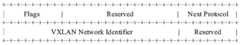
(1)VXLAN GPE Header:VXLAN通用协议封装首部,格式如图5所示。其中,8位的Flags字段是标志字段,长度为24位的VNI字段用于定义VXLAN网络中不同的租户,8 位的封装协议字段(Next Protocol)用于指明被封装的数据包的协议类型,封装协议字段为“SR_PRO”时,表示SR栈字段解析的标志位,用于指示此探测报文具有SR路径信息。(1) VXLAN GPE Header: VXLAN general protocol encapsulation header, the format is shown in Figure 5. Among them, the 8-bit Flags field is a flag field, the 24-bit VNI field is used to define different tenants in the VXLAN network, and the 8-bit encapsulation protocol field (Next Protocol) is used to indicate the protocol type of the encapsulated data packet. When the encapsulation protocol field is "SR_PRO", it indicates the flag bit of SR stack field parsing, which is used to indicate that this probe packet has SR path information.
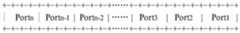
(2)SR Stack:源路由标签栈字段,报文格式如图6所示,由一系列设备输出端口ID组成。SR Stack嵌入在VXLAN GPE Header和INT Header之间,承载源路由路径控制算法。由于P4语言当前不支持在数据包头中进行可变长度堆栈的循环解析,因此本发明静态分配了具有固定长度的SR标签堆栈,并在INT Header上方为其保留了256位。具体地,在SR字段中,每个交换机输出端口ID占用4位,并通过右移操作(“>>”)执行出栈操作,弹出端口 ID。(2) SR Stack: source routing label stack field, the packet format is shown in Figure 6, and it consists of a series of device output port IDs. The SR Stack is embedded between the VXLAN GPE Header and the INT Header and carries the source routing path control algorithm. Since the P4 language currently does not support cyclic parsing of variable-length stacks in the packet header, the present invention statically allocates a fixed-length SR tag stack and reserves 256 bits for it above the INT Header. Specifically, in the SR field, the output port ID of each switch occupies 4 bits, and a pop operation is performed through a right shift operation (“>>”) to pop the port ID.
(3)INT Shim Header:用于VXLAN GPE封装的INT首部,报头格式如图7所示。长度为8位的类型字段(Type)用于指示INT首部类型,8位的长度字段(Length)用于记录INT首部和INT项目数据的总长度,8位的封装协议域字段(Next Protocol)用于指明被封装的数据包的协议类型。(3) INT Shim Header: INT header for VXLAN GPE encapsulation, the header format is shown in Figure 7. The 8-bit type field (Type) is used to indicate the type of the INT header, the 8-bit length field (Length) is used to record the total length of the INT header and the INT item data, and the 8-bit encapsulation protocol field (Next Protocol) is used for Used to indicate the protocol type of the encapsulated packet.
(4)INT Metadata Header:INT元数据首部,格式如图7所示。在INT元数据首部中,探测包每采集一个设备的状态信息,总跳数(Total Hop Cnt)值便加1。最大跳数字段(MaxHop Cnt)、指令设置字段(Instruction Bitmap)等均可在构造探测数据包时根据需求进行自定义设置。(4) INT Metadata Header: INT metadata header, the format is shown in Figure 7. In the INT metadata header, each time the probe packet collects the status information of a device, the value of the Total Hop Cnt is incremented by 1. The maximum hop number field (MaxHop Cnt), the instruction setting field (Instruction Bitmap), etc. can be customized according to the requirements when constructing the probe data packet.
(5)INT Metadata Stack:INT元数据栈字段,位于SR堆栈之上,具有可变长度。每条 INT元数据占据30字节,用于记录相关交换机的内部状态信息,例如设备ID、数据出入端口ID、队列情况、时延情况等。INT探测数据包经过一个交换机都会将指令设置字段中指定的数据信息添加到INT元数据字段的栈顶。(5) INT Metadata Stack: The INT metadata stack field, located above the SR stack, has a variable length. Each piece of INT metadata occupies 30 bytes and is used to record the internal status information of the relevant switch, such as device ID, data entry and exit port ID, queue status, delay status, etc. When an INT probe packet passes through a switch, the data information specified in the command setting field is added to the top of the stack in the INT metadata field.
(二)Overlay网络中探测数据包的解析处理逻辑(2) Analysis and processing logic of detection packets in the Overlay network
转发路径上的底层设备需要对经过的探测数据报文进行解析,以便后续处理。数据平面是整个监测系统的重要组成部分,本发明基于P4编程语言定义了数据平面中交换机对数据包的处理逻辑。解析器负责解析头字段,解析流程链路设备不仅支持Ethernet、IPv4数据包的转发,还支持UDP、VXLAN、SR和INT协议的封装,为执行校验和、逆解析等操作提供基础。The underlying device on the forwarding path needs to parse the passing probe data packets for subsequent processing. The data plane is an important part of the whole monitoring system, and the invention defines the processing logic of the data packets by the switch in the data plane based on the P4 programming language. The parser is responsible for parsing the header fields. The parsing process link device not only supports the forwarding of Ethernet and IPv4 packets, but also supports the encapsulation of UDP, VXLAN, SR, and INT protocols, providing the basis for performing checksum, reverse parsing, and other operations.
链路交换机接收到数据包开始解析,通过先后匹配Ethernet报头(即Ethernet报文首部) 中的以太网类型字段、IP报文的封装协议字段和UDP报文的目标端口字段,对数据包进行初步解析。随后,对VXLAN报文、SR报文和INT报文进行解析,如图8所示。如果VXLAN报文中的协议字段(vxlan_gpe.Next_Protocol)为“SR_PRO”,表明内部字段封装的是源路由字段,则进入SR栈字段进行解析,否则默认进入数据包处理入口(Ingress)。随后默认对INT报文进行解析,如果指令数字段(ins_cnt)的值为0,表示不需要采集任何信息,直接进入数据包处理入口;如果ins_cnt值非0,则进行解析交换机的INT信息值(int_value)。在解析INT元数据的过程中,由于其中含有多个类型相同的值,并且值的个数会随着数据包的转发不断地增加,因此需要使用堆栈(Header Stack)存储,如果某条INT元数据的栈底位(bos) 的值为1,说明已经遍历到栈底,int_value已经解析完毕,直接进入到数据包处理入口;如果bos位的值为0,说明还有int_value值未解析,需要继续循环解析,直到解析完堆栈中的所有值。VXLAN、SR和INT解析部分的关键代码如图9所示。After receiving the data packet, the link switch starts parsing it. By successively matching the Ethernet type field in the Ethernet header (that is, the Ethernet packet header), the encapsulation protocol field of the IP packet, and the destination port field of the UDP packet, the data packet is initially analyzed. Parse. Subsequently, the VXLAN packets, SR packets and INT packets are parsed, as shown in Figure 8. If the protocol field (vxlan_gpe.Next_Protocol) in the VXLAN packet is "SR_PRO", indicating that the internal field encapsulates the source routing field, enter the SR stack field for analysis, otherwise enter the packet processing entry (Ingress) by default. Then the INT packet is parsed by default. If the value of the instruction number field (ins_cnt) is 0, it means that no information needs to be collected, and it directly enters the data packet processing entry; if the value of ins_cnt is not 0, the INT information value of the switch is parsed ( int_value). In the process of parsing INT metadata, since it contains multiple values of the same type, and the number of values will continue to increase with the forwarding of data packets, it is necessary to use the Header Stack for storage. The value of the bottom bit of the stack (bos) of the data is 1, indicating that the bottom of the stack has been traversed, the int_value has been parsed, and directly enters the data packet processing entry; Continue to parse through the loop until all values on the stack have been parsed. The key code of VXLAN, SR and INT parsing part is shown in Figure 9.
(三)Overlay网络监测中DFS路径生成机制(3) DFS path generation mechanism in Overlay network monitoring
Overlay网络中的主机或服务器通信时,往往存在大量的重复监测路径。为了降低不必要的带宽占用和处理开销,应当提高网络遥测的覆盖性和可扩展性,减少重复探测路径的数量。本发明利用简洁有效的DFS方法,生成覆盖整个网络的更少探测路径。DFS(DepthFirst Search,深度优先遍历或深度优先搜索)是一种遍历树或图形数据结构的有效图算法,此方法的特点是优先搜索或遍历深度方向,它能够以任意顶点为根节点开始遍历,并对每一个可能的分支路径深入到不能再深入为止,而且每条边只访问一次。DFS路径生成策略的基本思想是,在回溯之前将访问的顶点连续添加到当前路径中。在监测系统的路径规划阶段,遍历过程利用了堆栈功能,它具有“后进先出(Last Input First Output,LIFO)”的特点。When the hosts or servers in the overlay network communicate, there are often a large number of duplicate monitoring paths. In order to reduce unnecessary bandwidth occupation and processing overhead, the coverage and scalability of network telemetry should be improved, and the number of repeated detection paths should be reduced. The present invention utilizes a concise and effective DFS method to generate fewer probe paths covering the entire network. DFS (DepthFirst Search, depth-first traversal or depth-first search) is an efficient graph algorithm for traversing tree or graph data structures. And for every possible branch path as far as it goes, each edge is visited only once. The basic idea of the DFS path generation strategy is to continuously add visited vertices to the current path before backtracking. In the path planning stage of the monitoring system, the traversal process utilizes the stack function, which has the characteristics of "Last Input First Output (LIFO)".
图10为一个包含8个设备的网络图,假设图中的左侧节点的搜索优先级高于右侧节点。遍历过程从顶点V1开始,该顶点被推入堆栈。随后搜索相邻顶点V2,如果边(V1,V2)没有被访问过,则将V2推入堆栈中,并将边(V1,V2)标记为已访问,此时路径为Path1=[V1,V2]。然后,以V2为新的起始顶点,继续进行遍历。类似地,将边(V2,V3)标记为已访问,并将V3推入堆栈之中,此时路径更新为Path1=[V1,V2,V3]。此时无法继续沿当前路径进行深度搜索,需要进行回溯操作,并将弹出的节点V2作为新路径的第一个顶点,这也是回溯路径的第一个具有未访问边缘的顶点。随后,从V2开始创建一个新路径,即Path2=[V2, V3]。当路径扩展为Path2=[V1,V4,V5]时,又无法继续沿深度搜索。因此,重复上述搜索与回溯过程,直到图中的所有边缘均被访问。最终,能够获得4条覆盖全图的非重叠INT探测路径,即Path1=[V1,V2,V3],Path2=[V2,V4,V5],Path3=[V1,V6,V7],Path4=[V6, V8]。DFS运算过程伪代码见图11。Figure 10 is a network diagram containing 8 devices. It is assumed that the search priority of the left node in the figure is higher than that of the right node. The traversal process starts with vertex V1, which is pushed onto the stack. Then search for the adjacent vertex V2, if the edge (V1, V2) has not been visited, push V2 into the stack, and mark the edge (V1, V2) as visited, at this time the path is Path1 = [V1, V2 ]. Then, with V2 as the new starting vertex, continue the traversal. Similarly, the edge (V2, V3) is marked as visited, and V3 is pushed into the stack, at this time the path is updated to Path1=[V1, V2, V3]. At this time, the depth search along the current path cannot be continued, and a backtracking operation is required, and the popped node V2 is used as the first vertex of the new path, which is also the first vertex of the backtracking path with an unvisited edge. Then, a new path is created starting from V2, ie Path2=[V2, V3]. When the path is expanded to Path2=[V1, V4, V5], the search along the depth cannot be continued. Therefore, the above search and backtracking process is repeated until all edges in the graph are visited. Finally, four non-overlapping INT detection paths covering the whole image can be obtained, namely Path1=[V1, V2, V3], Path2=[V2, V4, V5], Path3=[V1, V6, V7], Path4=[ V6, V8]. The pseudo code of the DFS operation process is shown in Figure 11.
(四)Overlay网络监测中源路由路径控制策略(4) Source routing path control strategy in overlay network monitoring
轻量级网络监测系统需要对探测路径进行合理规划,底层机制允许指定特定的监视路径,以解决路径不可控问题。基于该机制,本发明利用灵活的源路由策略对Overlay网络中的探测路径进行控制,定制每条探测路径的走向。具体地,将源路由嵌入到探测数据包之中,通过更改SR栈字段的值来指定每个交换机的输出端口,SR信息由控制器根据DFS算法计算得到,指引探测包有目的性地转发,所谓有目的性地转发指的是根据之前定制的探测路径的走向来进行探测包的转发。探测包具有“VXLAN+SR+INT”的报文格式,其中SR报文和INT报文均为堆栈结构,SR标签栈包括输出端口标签,INT信息栈包括设备标签和元数据列表。路由器通过弹出SR标签并插入INT标签完成一次遥测转发。A lightweight network monitoring system needs to plan the detection path reasonably, and the underlying mechanism allows specifying a specific monitoring path to solve the problem of uncontrollable paths. Based on this mechanism, the present invention uses a flexible source routing strategy to control the detection paths in the overlay network, and customizes the direction of each detection path. Specifically, the source route is embedded in the probe data packet, and the output port of each switch is specified by changing the value of the SR stack field. The SR information is calculated by the controller according to the DFS algorithm, and the probe packet is directed to be forwarded purposefully. The so-called purposeful forwarding refers to forwarding the detection packet according to the direction of the previously customized detection path. The detection packet has the packet format of "VXLAN+SR+INT", in which both the SR packet and the INT packet are stack structures, the SR label stack includes the output port label, and the INT information stack includes the device label and the metadata list. The router completes a telemetry forwarding by popping the SR tag and inserting the INT tag.
如图12所示,假设VTEP1与VTEP2之间的VXLAN隧道下对应的Underlay网络设备为交换机S1、S2和S3,基于源路由的探测包转发路径控制过程和INT信息采集过程可以概括为如下的步骤:As shown in Figure 12, assuming that the corresponding Underlay network devices under the VXLAN tunnel between VTEP1 and VTEP2 are switches S1, S2, and S3, the source routing-based detection packet forwarding path control process and INT information collection process can be summarized as the following steps :
(1)源端虚拟机(VM1,VM2)向终端虚拟机(VM3,VM4)发送数据帧,帧中包含了源端和终端虚拟机的IP和MAC地址信息。(1) The source virtual machines (VM1, VM2) send data frames to the terminal virtual machines (VM3, VM4), and the frames contain IP and MAC address information of the source and terminal virtual machines.
(2)源端虚拟机连接的VTEP节点(VTEP1)收到数据帧,通过查找源端所在的VXLAN以及终端所连接的VTEP节点,将该报文添加VXLAN报头以及外部报头,获得能够在 Overlay网络中传输的数据包。VTEP1同样作为INT源端,在VXLAN报头和Payload之间嵌入带有输出端口ID序列的SR栈报文和INT报头,构成探测包。此时,VTEP1即为带内网络遥测系统的第一个交换节点,INT模块通过在该节点上设置的采样方式匹配并镜像出该报文,根据遥测任务的需要将INT头部所指定的遥测信息封装成元数据(INT Meta 1)插入到INT Header之后。(2) The VTEP node (VTEP1) connected to the source virtual machine receives the data frame, and adds the VXLAN header and the external header to the packet by looking up the VXLAN where the source is located and the VTEP node connected to the terminal to obtain the information that can be used in the Overlay network. packets transmitted in. VTEP1 also acts as the INT source end, and embeds the SR stack message and the INT header with the output port ID sequence between the VXLAN header and the payload to form a probe packet. At this point, VTEP1 is the first switching node of the in-band network telemetry system. The INT module matches and mirrors the packet through the sampling method set on the node. According to the needs of the telemetry task, the telemetry specified in the INT header is The information is encapsulated into metadata (INT Meta 1) and inserted after the INT Header.
(3)探测包从VTEP1继续向后传输,如果VXLAN首部中的Next_Protocol字段为“SR_PRO”,则将SR标签栈右移4位来实现出栈(Stack Pop)操作,获取设备输出端口ID,从而确定转发路径。此时VTEP1的出口ID为2,下一设备为S1。(3) The probe packet continues to be transmitted backward from VTEP1. If the Next_Protocol field in the VXLAN header is "SR_PRO", the SR label stack is shifted right by 4 bits to realize the stack pop operation, and the device output port ID is obtained, thereby Determine the forwarding path. At this time, the egress ID of VTEP1 is 2, and the next device is S1.
(4)探测包抵达交换机S1后,设备匹配INT Header后插入元数据(INT Meta 2);随后将SR堆栈右移4位弹出标签,获取此设备的输出端口ID,继续传输。继续此步骤,直到数据包抵达终端VTEP节点(VTEP2)。(4) After the detection packet arrives at the switch S1, the device matches the INT Header and then inserts the metadata (INT Meta 2); then shifts the SR stack to the right by 4 bits to pop up the label, obtains the output port ID of the device, and continues transmission. Continue this step until the packet arrives at the terminating VTEP node (VTEP2).
(5)VTEP2接收到报文后,交换设备匹配INT Header插入最后一个元数据(INTMeta 5),将INT Header拆除,提取全部遥测信息上传到控制器。这样控制器就采集到了时延、拥塞等网络链路状态信息,控制器将信息解析后存储在数据库中。最后,检查报文的VNI以及内部数据帧的目的MAC地址,拆除VXLAN报头后将内部数据帧交付给终端虚拟机(VM3,VM4),传输完成。(5) After VTEP2 receives the message, the switching device matches the INT Header and inserts the last metadata (INTMeta 5), removes the INT Header, extracts all telemetry information and uploads it to the controller. In this way, the controller collects network link status information such as delay and congestion, and the controller parses the information and stores it in the database. Finally, check the VNI of the message and the destination MAC address of the internal data frame, remove the VXLAN header, and deliver the internal data frame to the terminal virtual machines (VM3, VM4), and the transmission is completed.
(五)INT监测信息的存储(5) Storage of INT monitoring information
INT探测数据包到达终点后,通过交换机与控制层之间建立的Socket连接,将采集到的 INT信息发送给控制层。本发明中,INT监测信息的存储主要由控制层实现:依据“两路探测”的监测方式,控制器维护数据库中的两个表格,用以存储数据层获取的网络监测信息。以图 13中的Fat Tree拓扑网络为例,此网络拓扑有4个pod、20台交换机和16台主机,在其上配置VXLAN并进行Overlay网络监测。After the INT detection data packet reaches the end point, the collected INT information is sent to the control layer through the Socket connection established between the switch and the control layer. In the present invention, the storage of INT monitoring information is mainly realized by the control layer: according to the monitoring method of "two-way detection", the controller maintains two tables in the database to store the network monitoring information obtained by the data layer. Take the Fat Tree topology network in Figure 13 as an example. This network topology has 4 pods, 20 switches and 16 hosts, on which VXLAN is configured and overlay network monitoring is performed.
本发明提出的Overlay网络监测方法分为两路探测:The Overlay network monitoring method proposed by the present invention is divided into two paths of detection:
第一路:按照DFS算法和SR机制规划的路径进行全网随路监测,数据包在转发过程中,根据指令设置字段设置的信息类别,沿路依次采集Underlay链路设备的各类内部状态信息;The first path: follow the path planned by the DFS algorithm and the SR mechanism to monitor the entire network. During the data packet forwarding process, according to the information category set in the command setting field, various kinds of internal status information of the Underlay link devices are collected along the path in turn;
第二路:当Overlay网络中任意主机之间进行通信时,数据包在对应链路中进行转发,只需要依次采集Underlay链路上设备的ID即可。The second way: When any host in the Overlay network communicates, the data packets are forwarded in the corresponding link, and it is only necessary to sequentially collect the IDs of the devices on the Underlay link.
进行Overlay网络全网探测时,控制器将采集到的Underlay链路上的INT信息解析并存储于“INT元数据表”之中,如表1所示。注意,表格的Key值是“switch_id”和“next_switch_id”,分别为当前设备的ID和下一设备的ID,Value值是“egress_port”、“deq_timedelta”和“process_delay”,分别为设备输出端口ID、排队时延和处理时延。INT时延信息单位精确到微秒,由P4交换机的端口时间戳等固有元数据计算得到。任意主机之间进行通信时,控制器将采集到的Underlay路径信息存储于“INT探测路径表”之中,如表2所示。其中,Key值为“End-to-end IP”,表示通信两端主机或服务器的IP地址,Value值为“Path”,表示数据包的转发路径,由沿路有序设备ID组成。During the whole network detection of the Overlay network, the controller parses the collected INT information on the Underlay link and stores it in the "INT metadata table", as shown in Table 1. Note that the Key values of the table are "switch_id" and "next_switch_id", which are the ID of the current device and the ID of the next device, respectively, and the Value values are "egress_port", "deq_timedelta" and "process_delay", which are the device output port ID, Queuing delay and processing delay. The unit of INT delay information is accurate to microseconds and is calculated from inherent metadata such as port timestamps of the P4 switch. When communicating between any host, the controller stores the collected Underlay path information in the "INT detection path table", as shown in Table 2. Among them, the Key value is "End-to-end IP", which indicates the IP addresses of the hosts or servers at both ends of the communication, and the Value value is "Path", which indicates the forwarding path of the data packet, which is composed of ordered device IDs along the path.
图14(a)和图14(b)展示了路径规划前后的INT采集信息,其中,实线为路径规划之前的探测信息,虚线为路径规划之后的探测信息。图14(a)展示了排队时延随探测时间间隔的变化情况,随着探测时间间隔的增大,路径规划前后的排队时延仍旧相近;图14(b)展示了处理时延随探测时间间隔的变化情况,随着探测时间间隔的增大,路径规划前后的处理时延差距略微增大。当全网采集频率高,探测时间间隔小时,按照低开销的规划路径采集到的底层设备状态信息可近似逼近每条Overlay链路对应的Underlay链路设备状态信息,因此能够采用轻量级的Overlay网络监测方法。Figures 14(a) and 14(b) show the INT acquisition information before and after path planning, where the solid line is the detection information before the path planning, and the dotted line is the detection information after the path planning. Figure 14(a) shows the variation of the queuing delay with the detection time interval. As the detection time interval increases, the queuing delay before and after path planning is still similar; Figure 14(b) shows the processing delay as a function of the detection time. The change of the interval, with the increase of the detection time interval, the difference of the processing delay before and after the path planning slightly increases. When the network-wide collection frequency is high and the detection interval is small, the underlying device status information collected according to the low-cost planned path can approximate the device status information of the Underlay link corresponding to each overlay link. Therefore, a lightweight overlay can be used. network monitoring methods.
表1 INT元数据表Table 1 INT metadata table

表2 INT探测路径表Table 2 INT detection path table

(六)INT监测信息的查询(6) Query of INT monitoring information
INT监测信息的查询主要由控制层实现:通过“两步查找”操作,控制器能够快速准确获取监测得到的设备状态信息。如图15所示,查询INT监测信息时,需要进行两步查找操作:The query of INT monitoring information is mainly realized by the control layer: through the "two-step search" operation, the controller can quickly and accurately obtain the equipment status information obtained by monitoring. As shown in Figure 15, when querying INT monitoring information, a two-step search operation is required:
第一步:通过两端主机的IP地址等Overlay隧道信息查询Underlay经过的有序设备ID。查询“INT探测路径表”,得到Overlay网络和对应Underlay网络的映射关系,获知数据转发路径。此时同样面临“N平方”问题,但因为只依次采集了设备ID,不采集端口上的链路状态,因此并不占用太多网络带宽。Step 1: Query the ordered device IDs that the Underlay passes through through the overlay tunnel information such as the IP addresses of the hosts at both ends. Query the "INT detection path table" to obtain the mapping relationship between the overlay network and the corresponding underlay network, and learn the data forwarding path. At this time, the "N squared" problem is also faced, but because only the device ID is collected in sequence, and the link status on the port is not collected, it does not occupy too much network bandwidth.
第二步:通过第一步查询所得的有序设备ID序列进一步查询每个设备的端口链路状态信息。“INT元数据表”中储存有以较小代价采集到的全网监测信息,根据转发路径的设备列表获得键值对“switch_id-next_switch_id”,即通过同时匹配“switch_id”和“next_switch_id”,来获得当前设备的内部状态信息。其中,设备列表中最后一个交换机没有后续交换机,则“next_switch_id”用“None”表示。The second step: further query the port link status information of each device through the ordered device ID sequence obtained by the first step query. The "INT metadata table" stores the network-wide monitoring information collected at a relatively low cost, and obtains the key-value pair "switch_id-next_switch_id" according to the device list of the forwarding path, that is, by matching "switch_id" and "next_switch_id" at the same time, Get the internal state information of the current device. Among them, if the last switch in the device list has no subsequent switches, "next_switch_id" is represented by "None".
具体地,以图13中的虚拟主机VM1和VM3通讯为例,根据双方的IP地址对“10.0.1.10-10.0.3.10”,查询表格“INT路径表”(第一次查表),得到传输路径[S1,S9,S2];随后根据路径得到设备ID“S1-S9”、“S9-S2”和“S2-None”,查询表格“INT元数据表”(第二次查表),从而获得设备S1、S9和S2的内部状态信息,例如,S1的输出端口ID为P3,排队时延为12微秒,处理时延为149微秒。两步查找策略减小了存储表的总体规模,以更小代价完成了监测信息的采集与查询。Specifically, taking the communication between the virtual hosts VM1 and VM3 in FIG. 13 as an example, according to the IP address pair "10.0.1.10-10.0.3.10" of the two parties, query the table "INT path table" (the first table lookup), and obtain the transmission Path [S1, S9, S2]; then obtain the device IDs "S1-S9", "S9-S2" and "S2-None" according to the path, and query the table "INT metadata table" (the second lookup table), thus Obtain the internal status information of devices S1, S9 and S2. For example, the output port ID of S1 is P3, the queuing delay is 12 microseconds, and the processing delay is 149 microseconds. The two-step search strategy reduces the overall size of the storage table, and completes the collection and query of monitoring information at a lower cost.
本发明同时还提供一种面向Overlay的轻量级带内网络遥测装置,包括报文封装模块、报文解析模块、探测路径生成模块、探测路径定制模块、探测信息存储模块和探测信息查询模块,所述报文封装模块用于对IP报文进行封装,以得到探测数据包,所述探测数据包能够依次采集沿途Underlay设备的ID以及设备端口侧的链路状态信息;所述报文解析模块用于对探测数据包进行解析;所述探测路径生成模块用于生成非重叠的探测路径;所述探测路径定制模块用于通过指定交换机的输出端口来指引探测数据包有目的性地转发,从而得到定制的探测数据包转发路径;所述探测信息存储模块用于存储采集到的网络监测信息;所述探测信息查询模块用于获取监测到的设备状态信息。The present invention also provides an overlay-oriented lightweight in-band network telemetry device, comprising a message encapsulation module, a message parsing module, a detection path generation module, a detection path customization module, a detection information storage module and a detection information query module, The message encapsulation module is used to encapsulate the IP message to obtain a detection data packet, which can sequentially collect the ID of the Underlay device along the way and the link status information on the port side of the device; the message parsing module used to parse the detection data packets; the detection path generation module is used to generate non-overlapping detection paths; the detection path customization module is used to guide the detection data packets to be forwarded purposefully by specifying the output port of the switch, thereby The customized detection data packet forwarding path is obtained; the detection information storage module is used for storing the collected network monitoring information; the detection information query module is used for acquiring the monitored device state information.
具体实施时,报文封装模块在原始报文(Original Payload)外部依次添加INT首部(INT Header)、源路由标签栈(SR Stack)和VXLAN首部(VXLAN GPE Header)来构造用于Overlay 网络信息采集的探测包,其中,INT首部由INT Shim Header、INT MetadataHeader和INT Metadata Stack三部分构成。继续添加UDP首部(UDP Header)、外部IP首部(Outer IP Header) 和外部Ether首部(Outer Ether Header),构成最终的探测数据包。During specific implementation, the packet encapsulation module sequentially adds INT header (INT Header), source routing label stack (SR Stack) and VXLAN header (VXLAN GPE Header) outside the original packet (Original Payload) to construct the overlay network information collection The detection package of INT header consists of three parts: INT Shim Header, INT MetadataHeader and INT Metadata Stack. Continue to add UDP Header, Outer IP Header and Outer Ether Header to form the final probe packet.
报文解析模块收到探测数据包后开始解析,通过先后匹配Ethernet报头(Ether首部)中的以太网类型字段、IP报文的封装协议字段和UDP报文的目标端口字段,对数据包进行初步解析。随后,对VXLAN报文、SR报文和INT报文进行解析,如图8所示。如果VXLAN报文中的协议字段(vxlan_gpe.Next_Protocol)为“SR_PRO”,表明内部字段封装的是源路由字段,则进入SR栈字段进行解析,否则默认进入数据包处理入口(Ingress)。随后默认对INT报文进行解析,如果指令数字段(ins_cnt)的值为0,表示不需要采集任何信息,直接进入数据包处理入口;如果ins_cnt值非0,则进行解析交换机的INT信息值(int_value)。在解析INT元数据的过程中,由于其中含有多个类型相同的值,并且值的个数会随着数据包的转发不断地增加,因此需要使用堆栈(Header Stack)存储,如果某条INT元数据的栈底位(bos)的值为1,说明已经遍历到栈底,int_value已经解析完毕,直接进入到数据包处理入口;如果bos位的值为0,说明还有int_value值未解析,需要继续循环解析,直到解析完堆栈中的所有值。The packet parsing module starts parsing after receiving the probe data packet. By successively matching the Ethernet type field in the Ethernet header (Ether header), the encapsulation protocol field of the IP packet, and the destination port field of the UDP packet, the packet is initially analyzed. Parse. Subsequently, the VXLAN packets, SR packets and INT packets are parsed, as shown in Figure 8. If the protocol field (vxlan_gpe.Next_Protocol) in the VXLAN packet is "SR_PRO", indicating that the internal field encapsulates the source routing field, enter the SR stack field for analysis, otherwise enter the packet processing entry (Ingress) by default. Then the INT packet is parsed by default. If the value of the instruction number field (ins_cnt) is 0, it means that no information needs to be collected, and it directly enters the data packet processing entry; if the value of ins_cnt is not 0, the INT information value of the switch is parsed ( int_value). In the process of parsing INT metadata, since it contains multiple values of the same type, and the number of values will continue to increase with the forwarding of data packets, it is necessary to use the Header Stack for storage. The value of the bottom bit of the stack (bos) of the data is 1, indicating that the bottom of the stack has been traversed, the int_value has been parsed, and directly enters the data packet processing entry; Continue to parse through the loop until all values on the stack have been parsed.
探测路径生成模块利用简洁有效的深度优先遍历方法,生成覆盖整个网络的更少探测路径。The probe path generation module utilizes a concise and efficient depth-first traversal method to generate fewer probe paths covering the entire network.
探测路径定制模块利用灵活的源路由策略对Overlay网络中的探测路径进行控制,定制每条探测路径的走向。具体地,将源路由嵌入到探测数据包之中,通过更改SR栈字段的值来指定每个交换机的输出端口,SR信息由控制器根据DFS算法计算得到探测数据包转发路径,指引探测包有目的性地转发。The detection path customization module uses flexible source routing policies to control the detection paths in the overlay network, and customizes the direction of each detection path. Specifically, the source route is embedded in the probe data packet, and the output port of each switch is specified by changing the value of the SR stack field. The SR information is calculated by the controller according to the DFS algorithm to obtain the probe data packet forwarding path. purposefully forwarded.
探测信息存储模块采用两路探测法以存储数据层获取的网络监测信息,其中,第一路:按照DFS算法和SR机制规划的路径进行全网随路监测,数据包在转发过程中,根据指令设置字段设置的信息类别,沿路依次采集Underlay链路设备的各类内部状态信息;第二路:当Overlay网络中任意主机之间进行通信时,数据包在对应链路中进行转发,只需要依次采集 Underlay链路上设备的ID即可。The detection information storage module adopts a two-way detection method to store the network monitoring information obtained by the data layer. Among them, the first way: according to the path planned by the DFS algorithm and the SR mechanism, the whole network is monitored along the road. During the forwarding process of the data packet, according to the instruction Set the information category set in the field, and collect all kinds of internal status information of the Underlay link devices along the way; the second way: when any host in the overlay network communicates, the data packets are forwarded in the corresponding link, and only need to be sequentially Collect the ID of the device on the Underlay link.
探测信息查询模块通过两步查找操作实现探测信息的查询:The detection information query module realizes the query of detection information through a two-step search operation:
第一步:通过两端主机的IP地址等Overlay隧道信息查询Underlay经过的有序设备ID。查询“INT探测路径表”,得到Overlay网络和对应Underlay网络的映射关系,获知数据转发路径。此时同样面临“N平方”问题,但因为只依次采集了设备ID,不采集端口上的链路状态,因此并不占用太多网络带宽。第二步:通过第一步查询所得的有序设备ID序列进一步查询每个设备的端口链路状态信息。Step 1: Query the ordered device IDs that the Underlay passes through through the overlay tunnel information such as the IP addresses of the hosts at both ends. Query the "INT detection path table" to obtain the mapping relationship between the overlay network and the corresponding underlay network, and learn the data forwarding path. At this time, the "N squared" problem is also faced, but because only the device ID is collected in sequence, and the link status on the port is not collected, it does not occupy too much network bandwidth. The second step: further query the port link status information of each device through the ordered device ID sequence obtained by the first step query.
本发明还提供一种计算机可读存储介质,所述计算机可读存储介质存储有计算机指令,所述计算机指令用于使所述计算机执行上述的面向Overlay的轻量级带内网络遥测方法。The present invention also provides a computer-readable storage medium, where computer instructions are stored in the computer-readable storage medium, and the computer instructions are used to cause the computer to execute the above-mentioned overlay-oriented lightweight in-band network telemetry method.
本发明基于P4语言定义了数据报文格式、设计了高级解析过程,基于DFS路径生成算法和SR路径控制策略提出了有效的探测路径规划机制,在不影响遥测性能的前提下,通过两路探测策略,使用更少的探测路径进行全网监测,克服了Overlay网络中用户进行通信时造成的大量重复探测路径问题,降低了网络监测开销。如图16(a)和图16(b)所示,在 pod数目为20的Fat-Tree拓扑网络中,路径规划前,网络中的INT报头达到25MB;路径规划控制后,网络中的INT报头仅为14KB。本发明提出的方法有效地减少了全网探测路径和控制器的储存消耗,明显降低了网络开销,实现了轻量级的带内网络遥测。Based on the P4 language, the invention defines the format of the data message, designs the advanced parsing process, and proposes an effective detection path planning mechanism based on the DFS path generation algorithm and the SR path control strategy. The strategy uses fewer detection paths to monitor the entire network, which overcomes the problem of a large number of repeated detection paths caused by users in the overlay network when communicating, and reduces network monitoring overhead. As shown in Figure 16(a) and Figure 16(b), in the Fat-Tree topology network with 20 pods, before the path planning, the INT header in the network reaches 25MB; after the path planning control, the INT header in the network reaches 25MB. Only 14KB. The method proposed by the invention effectively reduces the storage consumption of the whole network detection path and the controller, obviously reduces the network overhead, and realizes the lightweight in-band network telemetry.
Claims (10)
Translated fromChinesePriority Applications (1)
| Application Number | Priority Date | Filing Date | Title |
|---|---|---|---|
| CN202011515170.5ACN112702330B (en) | 2020-12-21 | 2020-12-21 | Lightweight in-band network telemetry method, device and storage medium for overlay network |
Applications Claiming Priority (1)
| Application Number | Priority Date | Filing Date | Title |
|---|---|---|---|
| CN202011515170.5ACN112702330B (en) | 2020-12-21 | 2020-12-21 | Lightweight in-band network telemetry method, device and storage medium for overlay network |
Publications (2)
| Publication Number | Publication Date |
|---|---|
| CN112702330A CN112702330A (en) | 2021-04-23 |
| CN112702330Btrue CN112702330B (en) | 2022-07-01 |
Family
ID=75507696
Family Applications (1)
| Application Number | Title | Priority Date | Filing Date |
|---|---|---|---|
| CN202011515170.5AActiveCN112702330B (en) | 2020-12-21 | 2020-12-21 | Lightweight in-band network telemetry method, device and storage medium for overlay network |
Country Status (1)
| Country | Link |
|---|---|
| CN (1) | CN112702330B (en) |
Families Citing this family (13)
| Publication number | Priority date | Publication date | Assignee | Title |
|---|---|---|---|---|
| CN113225229B (en)* | 2021-05-08 | 2022-04-05 | 北京邮电大学 | Distributed lightweight total network remote measuring method and device based on label |
| CN113296894B (en)* | 2021-06-03 | 2022-03-04 | 清华大学 | Method and device for planning internal active detection path of cloud network virtual private network |
| US11558310B2 (en)* | 2021-06-16 | 2023-01-17 | Mellanox Technologies, Ltd. | Low-latency delivery of in-band telemetry data |
| CN113938407B (en)* | 2021-09-02 | 2023-06-20 | 北京邮电大学 | Fault detection method and device for data center network based on in-band network telemetry system |
| CN114338127B (en)* | 2021-12-24 | 2024-02-09 | 天融信雄安网络安全技术有限公司 | Data transmission method and device for anonymous communication, electronic equipment and storage medium |
| CN115442275B (en)* | 2022-07-27 | 2024-02-27 | 北京邮电大学 | Hybrid telemetry method and system based on hierarchical trusted streams |
| CN115695202A (en)* | 2022-08-05 | 2023-02-03 | 网络通信与安全紫金山实验室 | Network detection method, device, equipment and readable storage medium |
| CN115442282B (en)* | 2022-08-31 | 2023-08-29 | 深圳市风云实业有限公司 | Data acquisition system and method |
| CN115766552B (en)* | 2022-11-04 | 2024-05-31 | 西安电子科技大学 | Network measurement method and device based on SRv and INT |
| CN116094985B (en)* | 2022-12-21 | 2024-11-26 | 山东省计算中心(国家超级计算济南中心) | A hybrid in-band network telemetry task transmission method and system |
| CN116208536B (en)* | 2023-01-12 | 2024-07-02 | 中国人民解放军国防科技大学 | A lightweight in-band telemetry device and method for high-speed interconnection network |
| CN116938753B (en)* | 2023-09-13 | 2023-12-29 | 中移(苏州)软件技术有限公司 | Data processing method and device and electronic equipment |
| CN118018447B (en)* | 2024-02-01 | 2024-09-10 | 山东师范大学 | Switch state monitoring method and system for remote control |
Citations (3)
| Publication number | Priority date | Publication date | Assignee | Title |
|---|---|---|---|---|
| CN108199924A (en)* | 2018-01-26 | 2018-06-22 | 北京邮电大学 | The whole network traffic visualization method and device based on band network telemetering |
| CN111130928A (en)* | 2019-12-10 | 2020-05-08 | 网络通信与安全紫金山实验室 | Network measurement method based on in-band detection in wide area network |
| CN111769998A (en)* | 2019-08-13 | 2020-10-13 | 北京京东尚科信息技术有限公司 | Method and device for detecting network delay state |
- 2020
- 2020-12-21CNCN202011515170.5Apatent/CN112702330B/enactiveActive
Patent Citations (3)
| Publication number | Priority date | Publication date | Assignee | Title |
|---|---|---|---|---|
| CN108199924A (en)* | 2018-01-26 | 2018-06-22 | 北京邮电大学 | The whole network traffic visualization method and device based on band network telemetering |
| CN111769998A (en)* | 2019-08-13 | 2020-10-13 | 北京京东尚科信息技术有限公司 | Method and device for detecting network delay state |
| CN111130928A (en)* | 2019-12-10 | 2020-05-08 | 网络通信与安全紫金山实验室 | Network measurement method based on in-band detection in wide area network |
Also Published As
| Publication number | Publication date |
|---|---|
| CN112702330A (en) | 2021-04-23 |
Similar Documents
| Publication | Publication Date | Title |
|---|---|---|
| CN112702330B (en) | Lightweight in-band network telemetry method, device and storage medium for overlay network | |
| CN112866075B (en) | In-band network telemetering method, system and related device for Overlay network | |
| CN112422498B (en) | A method, system, and computer-readable storage medium for in-band network telemetry | |
| US12309064B2 (en) | Method for forwarding packet in SRv6 service function chain, SFF, and SF device | |
| EP3139560B1 (en) | Packet processing method, device and computer storage medium | |
| US12199794B2 (en) | Packet sending method, apparatus, and system | |
| US10728139B2 (en) | Flexible software-defined networking (SDN) protocol for service provider networks | |
| CN115426305B (en) | Message processing method, device, system and storage medium | |
| CN113938405B (en) | A method and device for data processing | |
| US10904123B2 (en) | Trace routing in virtual networks | |
| US20230327983A1 (en) | Performance measurement in a segment routing network | |
| EP3461080B1 (en) | Topology determination method, message response method, controller and switch | |
| WO2022007702A1 (en) | Message processing method and network device | |
| CN113037542B (en) | A cloud network topology construction method based on software-defined network | |
| CN112532468B (en) | Network measurement system, method, device and storage medium | |
| Zhang et al. | Vxlan-based int: In-band network telemetry for overlay network monitoring | |
| CN113765809A (en) | BIER multicast traffic statistics method, device and system | |
| CN116055341A (en) | A statistical method and system for virtual machine traffic in a cloud network | |
| US11962673B2 (en) | Packet tunneling and decapsulation with split-horizon attributes | |
| Zheng et al. | Enabling in-band network telemetry in software-based virtual switches | |
| CN115134273A (en) | Message processing method and related equipment | |
| Kushwaha et al. | Bitstream: A flexible SDN protocol for service provider networks | |
| CN119728540A (en) | Data packet processing method, device, equipment, medium and product | |
| WO2025103035A1 (en) | Network performance monitoring method and apparatus | |
| WO2025026071A1 (en) | Communication method and device |
Legal Events
| Date | Code | Title | Description |
|---|---|---|---|
| PB01 | Publication | ||
| PB01 | Publication | ||
| SE01 | Entry into force of request for substantive examination | ||
| SE01 | Entry into force of request for substantive examination | ||
| GR01 | Patent grant | ||
| GR01 | Patent grant | ||
| CP03 | Change of name, title or address | Address after:No. 9 Mozhou East Road, Nanjing City, Jiangsu Province, 211111 Patentee after:Zijinshan Laboratory Country or region after:China Address before:No. 9 Mozhou East Road, Jiangning Economic Development Zone, Jiangning District, Nanjing City, Jiangsu Province Patentee before:Purple Mountain Laboratories Country or region before:China | |
| CP03 | Change of name, title or address |