CN112689716B - Blood pump shaft bearing - Google Patents
Blood pump shaft bearingDownload PDFInfo
- Publication number
- CN112689716B CN112689716BCN201980059651.9ACN201980059651ACN112689716BCN 112689716 BCN112689716 BCN 112689716BCN 201980059651 ACN201980059651 ACN 201980059651ACN 112689716 BCN112689716 BCN 112689716B
- Authority
- CN
- China
- Prior art keywords
- bearing
- drive shaft
- impeller
- base
- blood pump
- Prior art date
- Legal status (The legal status is an assumption and is not a legal conclusion. Google has not performed a legal analysis and makes no representation as to the accuracy of the status listed.)
- Active
Links
Images


Classifications
- A—HUMAN NECESSITIES
- A61—MEDICAL OR VETERINARY SCIENCE; HYGIENE
- A61M—DEVICES FOR INTRODUCING MEDIA INTO, OR ONTO, THE BODY; DEVICES FOR TRANSDUCING BODY MEDIA OR FOR TAKING MEDIA FROM THE BODY; DEVICES FOR PRODUCING OR ENDING SLEEP OR STUPOR
- A61M60/00—Blood pumps; Devices for mechanical circulatory actuation; Balloon pumps for circulatory assistance
- A61M60/80—Constructional details other than related to driving
- A61M60/802—Constructional details other than related to driving of non-positive displacement blood pumps
- A61M60/818—Bearings
- A61M60/824—Hydrodynamic or fluid film bearings
- F—MECHANICAL ENGINEERING; LIGHTING; HEATING; WEAPONS; BLASTING
- F16—ENGINEERING ELEMENTS AND UNITS; GENERAL MEASURES FOR PRODUCING AND MAINTAINING EFFECTIVE FUNCTIONING OF MACHINES OR INSTALLATIONS; THERMAL INSULATION IN GENERAL
- F16C—SHAFTS; FLEXIBLE SHAFTS; ELEMENTS OR CRANKSHAFT MECHANISMS; ROTARY BODIES OTHER THAN GEARING ELEMENTS; BEARINGS
- F16C17/00—Sliding-contact bearings for exclusively rotary movement
- F16C17/04—Sliding-contact bearings for exclusively rotary movement for axial load only
- F16C17/08—Sliding-contact bearings for exclusively rotary movement for axial load only for supporting the end face of a shaft or other member, e.g. footstep bearings
- A—HUMAN NECESSITIES
- A61—MEDICAL OR VETERINARY SCIENCE; HYGIENE
- A61M—DEVICES FOR INTRODUCING MEDIA INTO, OR ONTO, THE BODY; DEVICES FOR TRANSDUCING BODY MEDIA OR FOR TAKING MEDIA FROM THE BODY; DEVICES FOR PRODUCING OR ENDING SLEEP OR STUPOR
- A61M60/00—Blood pumps; Devices for mechanical circulatory actuation; Balloon pumps for circulatory assistance
- A61M60/10—Location thereof with respect to the patient's body
- A61M60/122—Implantable pumps or pumping devices, i.e. the blood being pumped inside the patient's body
- A61M60/126—Implantable pumps or pumping devices, i.e. the blood being pumped inside the patient's body implantable via, into, inside, in line, branching on, or around a blood vessel
- A61M60/13—Implantable pumps or pumping devices, i.e. the blood being pumped inside the patient's body implantable via, into, inside, in line, branching on, or around a blood vessel by means of a catheter allowing explantation, e.g. catheter pumps temporarily introduced via the vascular system
- A—HUMAN NECESSITIES
- A61—MEDICAL OR VETERINARY SCIENCE; HYGIENE
- A61M—DEVICES FOR INTRODUCING MEDIA INTO, OR ONTO, THE BODY; DEVICES FOR TRANSDUCING BODY MEDIA OR FOR TAKING MEDIA FROM THE BODY; DEVICES FOR PRODUCING OR ENDING SLEEP OR STUPOR
- A61M60/00—Blood pumps; Devices for mechanical circulatory actuation; Balloon pumps for circulatory assistance
- A61M60/20—Type thereof
- A61M60/205—Non-positive displacement blood pumps
- A61M60/216—Non-positive displacement blood pumps including a rotating member acting on the blood, e.g. impeller
- A61M60/221—Non-positive displacement blood pumps including a rotating member acting on the blood, e.g. impeller the blood flow through the rotating member having both radial and axial components, e.g. mixed flow pumps
- A—HUMAN NECESSITIES
- A61—MEDICAL OR VETERINARY SCIENCE; HYGIENE
- A61M—DEVICES FOR INTRODUCING MEDIA INTO, OR ONTO, THE BODY; DEVICES FOR TRANSDUCING BODY MEDIA OR FOR TAKING MEDIA FROM THE BODY; DEVICES FOR PRODUCING OR ENDING SLEEP OR STUPOR
- A61M60/00—Blood pumps; Devices for mechanical circulatory actuation; Balloon pumps for circulatory assistance
- A61M60/20—Type thereof
- A61M60/205—Non-positive displacement blood pumps
- A61M60/216—Non-positive displacement blood pumps including a rotating member acting on the blood, e.g. impeller
- A61M60/237—Non-positive displacement blood pumps including a rotating member acting on the blood, e.g. impeller the blood flow through the rotating member having mainly axial components, e.g. axial flow pumps
- A—HUMAN NECESSITIES
- A61—MEDICAL OR VETERINARY SCIENCE; HYGIENE
- A61M—DEVICES FOR INTRODUCING MEDIA INTO, OR ONTO, THE BODY; DEVICES FOR TRANSDUCING BODY MEDIA OR FOR TAKING MEDIA FROM THE BODY; DEVICES FOR PRODUCING OR ENDING SLEEP OR STUPOR
- A61M60/00—Blood pumps; Devices for mechanical circulatory actuation; Balloon pumps for circulatory assistance
- A61M60/40—Details relating to driving
- A61M60/403—Details relating to driving for non-positive displacement blood pumps
- A61M60/422—Details relating to driving for non-positive displacement blood pumps the force acting on the blood contacting member being electromagnetic, e.g. using canned motor pumps
- A—HUMAN NECESSITIES
- A61—MEDICAL OR VETERINARY SCIENCE; HYGIENE
- A61M—DEVICES FOR INTRODUCING MEDIA INTO, OR ONTO, THE BODY; DEVICES FOR TRANSDUCING BODY MEDIA OR FOR TAKING MEDIA FROM THE BODY; DEVICES FOR PRODUCING OR ENDING SLEEP OR STUPOR
- A61M60/00—Blood pumps; Devices for mechanical circulatory actuation; Balloon pumps for circulatory assistance
- A61M60/50—Details relating to control
- A61M60/508—Electronic control means, e.g. for feedback regulation
- A—HUMAN NECESSITIES
- A61—MEDICAL OR VETERINARY SCIENCE; HYGIENE
- A61M—DEVICES FOR INTRODUCING MEDIA INTO, OR ONTO, THE BODY; DEVICES FOR TRANSDUCING BODY MEDIA OR FOR TAKING MEDIA FROM THE BODY; DEVICES FOR PRODUCING OR ENDING SLEEP OR STUPOR
- A61M60/00—Blood pumps; Devices for mechanical circulatory actuation; Balloon pumps for circulatory assistance
- A61M60/80—Constructional details other than related to driving
- A61M60/802—Constructional details other than related to driving of non-positive displacement blood pumps
- A61M60/818—Bearings
- A61M60/825—Contact bearings, e.g. ball-and-cup or pivot bearings
- A—HUMAN NECESSITIES
- A61—MEDICAL OR VETERINARY SCIENCE; HYGIENE
- A61M—DEVICES FOR INTRODUCING MEDIA INTO, OR ONTO, THE BODY; DEVICES FOR TRANSDUCING BODY MEDIA OR FOR TAKING MEDIA FROM THE BODY; DEVICES FOR PRODUCING OR ENDING SLEEP OR STUPOR
- A61M60/00—Blood pumps; Devices for mechanical circulatory actuation; Balloon pumps for circulatory assistance
- A61M60/80—Constructional details other than related to driving
- A61M60/802—Constructional details other than related to driving of non-positive displacement blood pumps
- A61M60/827—Sealings between moving parts
- A61M60/829—Sealings between moving parts having a purge fluid supply
- F—MECHANICAL ENGINEERING; LIGHTING; HEATING; WEAPONS; BLASTING
- F04—POSITIVE - DISPLACEMENT MACHINES FOR LIQUIDS; PUMPS FOR LIQUIDS OR ELASTIC FLUIDS
- F04D—NON-POSITIVE-DISPLACEMENT PUMPS
- F04D13/00—Pumping installations or systems
- F04D13/02—Units comprising pumps and their driving means
- F04D13/021—Units comprising pumps and their driving means containing a coupling
- F04D13/024—Units comprising pumps and their driving means containing a coupling a magnetic coupling
- F04D13/026—Details of the bearings
- F—MECHANICAL ENGINEERING; LIGHTING; HEATING; WEAPONS; BLASTING
- F04—POSITIVE - DISPLACEMENT MACHINES FOR LIQUIDS; PUMPS FOR LIQUIDS OR ELASTIC FLUIDS
- F04D—NON-POSITIVE-DISPLACEMENT PUMPS
- F04D29/00—Details, component parts, or accessories
- F04D29/04—Shafts or bearings, or assemblies thereof
- F04D29/046—Bearings
- F04D29/0467—Spherical bearings
- F—MECHANICAL ENGINEERING; LIGHTING; HEATING; WEAPONS; BLASTING
- F16—ENGINEERING ELEMENTS AND UNITS; GENERAL MEASURES FOR PRODUCING AND MAINTAINING EFFECTIVE FUNCTIONING OF MACHINES OR INSTALLATIONS; THERMAL INSULATION IN GENERAL
- F16C—SHAFTS; FLEXIBLE SHAFTS; ELEMENTS OR CRANKSHAFT MECHANISMS; ROTARY BODIES OTHER THAN GEARING ELEMENTS; BEARINGS
- F16C33/00—Parts of bearings; Special methods for making bearings or parts thereof
- F16C33/02—Parts of sliding-contact bearings
- F16C33/04—Brasses; Bushes; Linings
- F16C33/06—Sliding surface mainly made of metal
- F16C33/10—Construction relative to lubrication
- F16C33/1025—Construction relative to lubrication with liquid, e.g. oil, as lubricant
- F16C33/103—Construction relative to lubrication with liquid, e.g. oil, as lubricant retained in or near the bearing
- F—MECHANICAL ENGINEERING; LIGHTING; HEATING; WEAPONS; BLASTING
- F16—ENGINEERING ELEMENTS AND UNITS; GENERAL MEASURES FOR PRODUCING AND MAINTAINING EFFECTIVE FUNCTIONING OF MACHINES OR INSTALLATIONS; THERMAL INSULATION IN GENERAL
- F16C—SHAFTS; FLEXIBLE SHAFTS; ELEMENTS OR CRANKSHAFT MECHANISMS; ROTARY BODIES OTHER THAN GEARING ELEMENTS; BEARINGS
- F16C33/00—Parts of bearings; Special methods for making bearings or parts thereof
- F16C33/02—Parts of sliding-contact bearings
- F16C33/04—Brasses; Bushes; Linings
- F16C33/06—Sliding surface mainly made of metal
- F16C33/10—Construction relative to lubrication
- F16C33/1025—Construction relative to lubrication with liquid, e.g. oil, as lubricant
- F16C33/1045—Details of supply of the liquid to the bearing
- F—MECHANICAL ENGINEERING; LIGHTING; HEATING; WEAPONS; BLASTING
- F16—ENGINEERING ELEMENTS AND UNITS; GENERAL MEASURES FOR PRODUCING AND MAINTAINING EFFECTIVE FUNCTIONING OF MACHINES OR INSTALLATIONS; THERMAL INSULATION IN GENERAL
- F16C—SHAFTS; FLEXIBLE SHAFTS; ELEMENTS OR CRANKSHAFT MECHANISMS; ROTARY BODIES OTHER THAN GEARING ELEMENTS; BEARINGS
- F16C33/00—Parts of bearings; Special methods for making bearings or parts thereof
- F16C33/02—Parts of sliding-contact bearings
- F16C33/04—Brasses; Bushes; Linings
- F16C33/06—Sliding surface mainly made of metal
- F16C33/10—Construction relative to lubrication
- F16C33/1025—Construction relative to lubrication with liquid, e.g. oil, as lubricant
- F16C33/106—Details of distribution or circulation inside the bearings, e.g. details of the bearing surfaces to affect flow or pressure of the liquid
- F16C33/1065—Grooves on a bearing surface for distributing or collecting the liquid
- F—MECHANICAL ENGINEERING; LIGHTING; HEATING; WEAPONS; BLASTING
- F16—ENGINEERING ELEMENTS AND UNITS; GENERAL MEASURES FOR PRODUCING AND MAINTAINING EFFECTIVE FUNCTIONING OF MACHINES OR INSTALLATIONS; THERMAL INSULATION IN GENERAL
- F16C—SHAFTS; FLEXIBLE SHAFTS; ELEMENTS OR CRANKSHAFT MECHANISMS; ROTARY BODIES OTHER THAN GEARING ELEMENTS; BEARINGS
- F16C2316/00—Apparatus in health or amusement
- F16C2316/10—Apparatus in health or amusement in medical appliances, e.g. in diagnosis, dentistry, instruments, prostheses, medical imaging appliances
- F16C2316/18—Pumps for pumping blood
Landscapes
- Engineering & Computer Science (AREA)
- Health & Medical Sciences (AREA)
- Heart & Thoracic Surgery (AREA)
- Mechanical Engineering (AREA)
- General Engineering & Computer Science (AREA)
- General Health & Medical Sciences (AREA)
- Cardiology (AREA)
- Hematology (AREA)
- Life Sciences & Earth Sciences (AREA)
- Animal Behavior & Ethology (AREA)
- Anesthesiology (AREA)
- Public Health (AREA)
- Veterinary Medicine (AREA)
- Biomedical Technology (AREA)
- Chemical & Material Sciences (AREA)
- Oil, Petroleum & Natural Gas (AREA)
- Fluid Mechanics (AREA)
- Physics & Mathematics (AREA)
- Vascular Medicine (AREA)
- External Artificial Organs (AREA)
- Structures Of Non-Positive Displacement Pumps (AREA)
- Sliding-Contact Bearings (AREA)
Abstract
Description
Translated fromChinese相关申请的交叉引用Cross References to Related Applications
本申请要求于2018年10月18日提交的临时申请号62/747,346的优先权权益,其全部内容通过引用并入本文。This application claims the benefit of priority to Provisional Application No. 62/747,346, filed October 18, 2018, the entire contents of which are incorporated herein by reference.
技术领域technical field
本发明涉及经皮循环支持装置。更具体地,本发明涉及在经皮循环支持装置中使用的轴承。The present invention relates to a percutaneous circulatory support device. More specifically, the present invention relates to bearings used in percutaneous circulatory support devices.
背景技术Background technique
经皮循环支持装置,诸如血泵通常为长达约三周的连续使用提供循环支持。轴承表面的磨损会限制装置的寿命。另外,在轴承表面处生成的热量以及与血液的机械交互可能导致溶血,这可能进一步导致健康并发症,诸如贫血,从而需要输血。Percutaneous circulatory support devices, such as blood pumps, typically provide circulatory support for up to about three weeks of continuous use. Wear on the bearing surfaces can limit the life of the unit. Additionally, the heat generated at the bearing surface and the mechanical interaction with the blood can lead to hemolysis, which can further lead to health complications such as anemia, requiring blood transfusions.
发明内容Contents of the invention
在示例1中,一种配置为保持血泵的驱动轴的端部的轴承组件,轴承组件包括轴承以及配置为保持润滑剂的润滑剂室。In Example 1, a bearing assembly configured to hold an end of a drive shaft of a blood pump, the bearing assembly includes a bearing and a lubricant chamber configured to hold lubricant.
在示例2中,示例1中的轴承组件,其中驱动轴的端部至少部分是圆形的,并且轴承包括限定在轴承第一侧中凹入的凹陷,其中凹陷配置为接收驱动轴的端部。In Example 2, the bearing assembly of Example 1, wherein the end of the drive shaft is at least partially circular, and the bearing includes a recess defined in the first side of the bearing, wherein the recess is configured to receive the end of the drive shaft .
在示例3中,示例1或2中的轴承组件,还包括杯形垫圈,其具有基座和远离基座延伸的周壁,从而形成由周壁的内表面和基座的内表面界定的腔室,其中轴承配置为至少部分地设置在腔室内。In Example 3, the bearing assembly of Examples 1 or 2, further comprising a cup washer having a base and a peripheral wall extending away from the base to form a cavity bounded by an inner surface of the peripheral wall and an inner surface of the base, Wherein the bearing is configured to be disposed at least partially within the chamber.
在示例4中,示例3中的轴承组件,杯形垫圈还包括限定在基座中的轴孔,其从基座外表面延伸至基座内表面,其中轴孔配置为接收驱动轴的一部分。In Example 4, the bearing assembly of Example 3, the cup washer further includes a shaft hole defined in the base extending from the base outer surface to the base inner surface, wherein the shaft hole is configured to receive a portion of the drive shaft.
在示例5中,示例3或4中的轴承组件,其中润滑剂室的至少一部分限定在杯形垫圈的周壁内表面、杯形垫圈的基座内表面和轴承的第一侧之间。In Example 5, the bearing assembly of Examples 3 or 4, wherein at least a portion of the lubricant chamber is defined between the inner surface of the peripheral wall of the cup washer, the inner surface of the base of the cup washer, and the first side of the bearing.
在示例6中,示例2中的轴承组件,润滑剂室包括限定在轴承第二侧中的至少一个通道,其穿过凹陷,其中至少一个通道配置为保持润滑剂。In Example 6, the bearing assembly of Example 2, the lubricant chamber includes at least one passage defined in the second side of the bearing through the recess, wherein the at least one passage is configured to retain lubricant.
在示例7中,一种血泵,包括叶轮、连结到叶轮并配置为与叶轮一起旋转的驱动轴、配置为驱动叶轮的马达以及邻近马达设置并配置为接收驱动轴的端部的轴承组件,轴承组件包括轴承,其中驱动轴的端部至少部分是圆形的,并且其中轴承包括限定在轴承第一侧中凹入的凹陷,其中凹陷配置为接收驱动轴的端部。In Example 7, a blood pump comprising an impeller, a drive shaft coupled to the impeller and configured to rotate with the impeller, a motor configured to drive the impeller, and a bearing assembly disposed adjacent the motor and configured to receive an end of the drive shaft, The bearing assembly includes a bearing, wherein the end of the drive shaft is at least partially circular, and wherein the bearing includes a recess defined in a first side of the bearing, wherein the recess is configured to receive the end of the drive shaft.
在示例8中,示例7中的血泵,轴承组件还包括配置为保持润滑剂的润滑剂室。In Example 8, the blood pump of Example 7, the bearing assembly further includes a lubricant chamber configured to retain lubricant.
在示例9中,示例8中的血泵,轴承组件还包括杯形垫圈,杯形垫圈具有基座和远离基座延伸的周壁,从而形成由周壁的内表面和基座的内表面界定的腔室,其中轴承配置为至少部分地设置在腔室内。In Example 9, the blood pump of Example 8, the bearing assembly further includes a cup washer having a base and a peripheral wall extending away from the base to form a cavity bounded by an inner surface of the peripheral wall and an inner surface of the base chamber, wherein the bearing is configured to be disposed at least partially within the chamber.
在示例10中,示例9中的血泵,杯形垫圈还包括限定在基座中的轴孔,其从基座的外表面延伸至基座的内表面,其中轴孔配置为接收驱动轴的一部分。In Example 10, the blood pump of Example 9, the cup washer further includes a shaft hole defined in the base extending from an outer surface of the base to an inner surface of the base, wherein the shaft hole is configured to receive the shaft of the drive shaft part.
在示例11中,示例9或10中的血泵,其中润滑剂室的至少一部分限定在杯形垫圈的周壁内表面、杯形垫圈的基座内表面和轴承的第一侧之间。In Example 11, the blood pump of Examples 9 or 10, wherein at least a portion of the lubricant chamber is defined between the inner surface of the peripheral wall of the cup washer, the inner surface of the base of the cup washer, and the first side of the bearing.
在示例12中,示例8中的血泵,其中润滑剂室至少部分地限定在轴承内。In Example 12, the blood pump of Example 8, wherein the lubricant chamber is at least partially defined within the bearing.
在示例13中,示例12中的血泵,润滑剂室包括限定在轴承第二侧中的至少一个通道,其穿过凹陷,其中至少一个通道配置为保持润滑剂。In Example 13, the blood pump of Example 12, the lubricant chamber includes at least one passage defined in the second side of the bearing through the recess, wherein the at least one passage is configured to retain lubricant.
在示例14中,示例13中的血泵,至少一个通道包括在凹陷中彼此相交的两个通道。In Example 14, the blood pump of Example 13, the at least one channel includes two channels intersecting each other in the recess.
在示例15中,示例8中的血泵,轴承组件包括在驱动轴和固定轴安装销的交叉处的柱状轴承,其中驱动轴配置为相对于固定轴安装销旋转,并且其中润滑剂室限定在轴承的内表面和固定轴安装销的外表面之间。In Example 15, the blood pump of Example 8, the bearing assembly includes a cylindrical bearing at the intersection of the drive shaft and the fixed shaft mounting pin, wherein the drive shaft is configured to rotate relative to the fixed shaft mounting pin, and wherein the lubricant chamber is defined in between the inner surface of the bearing and the outer surface of the fixed shaft mounting pin.
在示例16中,一种配置为保持血泵的驱动轴的端部的轴承组件,轴承组件包括轴承、以及配置为保持润滑剂的润滑剂室。In Example 16, a bearing assembly configured to hold an end of a drive shaft of a blood pump, the bearing assembly includes a bearing, and a lubricant chamber configured to hold lubricant.
在示例17中,示例16中的轴承组件,其中驱动轴的端部至少部分是圆形的,并且轴承包括限定在轴承第一侧中凹入的凹陷,其中凹陷配置为接收驱动轴的端部。In example 17, the bearing assembly of example 16, wherein the end of the drive shaft is at least partially circular, and the bearing includes a recess defined in the first side of the bearing, wherein the recess is configured to receive the end of the drive shaft .
在示例18中,示例16中的轴承组件,还包括杯形垫圈,其具有基座和远离基座延伸的周壁,从而形成由周壁的内表面和基座的内表面界定的腔室,其中轴承配置为至少部分地设置在腔室内。In Example 18, the bearing assembly of Example 16, further comprising a cup washer having a base and a peripheral wall extending away from the base to form a chamber bounded by an inner surface of the peripheral wall and an inner surface of the base, wherein the bearing configured to be disposed at least partially within the chamber.
在示例19中,示例18中的轴承组件,杯形垫圈还包括限定在基座中的轴孔,其从基座的外表面延伸至基座的内表面,其中轴孔配置为接收驱动轴的一部分。In Example 19, the bearing assembly of Example 18, the cup washer further includes a shaft hole defined in the base extending from the outer surface of the base to the inner surface of the base, wherein the shaft hole is configured to receive the shaft of the drive shaft part.
在示例20中,示例19中的轴承组件,其中润滑剂室的至少一部分限定在杯形垫圈的周壁内表面、杯形垫圈的基座内表面和轴承的第一侧之间。In Example 20, the bearing assembly of Example 19, wherein at least a portion of the lubricant chamber is defined between the inner surface of the peripheral wall of the cup washer, the inner surface of the base of the cup washer, and the first side of the bearing.
在示例21中,示例16中的轴承组件,其中润滑剂室至少部分地限定在轴承内。In Example 21, the bearing assembly of Example 16, wherein the lubricant chamber is at least partially defined within the bearing.
在示例22中,示例21中的轴承组件,润滑剂室包括限定在轴承第二侧中的至少一个通道,其穿过凹陷,其中至少一个通道配置为保持润滑剂。In Example 22, the bearing assembly of Example 21, the lubricant chamber includes at least one passage defined in the second side of the bearing that passes through the recess, wherein the at least one passage is configured to retain lubricant.
在示例23中,一种血泵,包括叶轮、连结到叶轮并配置为与叶轮一起旋转的驱动轴、配置为驱动叶轮的马达以及邻近马达设置并配置为接收驱动轴的端部的轴承组件,轴承组件包括轴承,其中驱动轴的端部至少部分是圆形的,并且其中轴承包括限定在轴承第一侧中凹入的凹陷,其中凹陷配置为接收驱动轴的端部。In Example 23, a blood pump comprising an impeller, a drive shaft coupled to the impeller and configured to rotate with the impeller, a motor configured to drive the impeller, and a bearing assembly disposed adjacent the motor and configured to receive an end of the drive shaft, The bearing assembly includes a bearing, wherein the end of the drive shaft is at least partially circular, and wherein the bearing includes a recess defined in a first side of the bearing, wherein the recess is configured to receive the end of the drive shaft.
在示例24中,示例22中的血泵,轴承组件还包括配置为保持润滑剂的润滑剂室。In Example 24, the blood pump of Example 22, the bearing assembly further includes a lubricant chamber configured to retain lubricant.
在示例25中,示例24中的血泵,轴承组件还包括杯形垫圈,其具有基座和远离基座延伸的周壁,从而形成由周壁的内表面和基座的内表面界定的腔室,其中轴承配置为至少部分地设置在腔室内。In Example 25, the blood pump of Example 24, the bearing assembly further includes a cup washer having a base and a peripheral wall extending away from the base to form a chamber bounded by an inner surface of the peripheral wall and an inner surface of the base, Wherein the bearing is configured to be disposed at least partially within the chamber.
在示例26中,示例24中的血泵,杯形垫圈还包括限定在杯形垫圈的基座中的轴孔,其从基座的外表面延伸至基座的内表面,其中轴孔配置为接收驱动轴的一部分。In Example 26, the blood pump of Example 24, the cup washer further includes a shaft hole defined in the base of the cup washer extending from an outer surface of the base to an inner surface of the base, wherein the shaft hole is configured as Receives part of the drive shaft.
在示例27中,示例24中的血泵,其中润滑剂室的至少一部分限定在杯形垫圈的周壁内表面、杯形垫圈的基座内表面和轴承的第一侧之间。In Example 27, the blood pump of Example 24, wherein at least a portion of the lubricant chamber is defined between the inner surface of the peripheral wall of the cup washer, the inner surface of the base of the cup washer, and the first side of the bearing.
在示例28中,示例24中的血泵,其中润滑剂室至少部分地限定在轴承内。In Example 28, the blood pump of Example 24, wherein the lubricant chamber is at least partially defined within the bearing.
在示例29中,示例28中的血泵,润滑剂室包括限定在轴承第二侧中的至少一个通道,其穿过凹陷,其中至少一个通道配置为保持润滑剂。In Example 29, the blood pump of Example 28, the lubricant chamber includes at least one passage defined in the second side of the bearing that passes through the recess, wherein the at least one passage is configured to retain lubricant.
在示例30中,示例29中的血泵,至少一个通道包括在凹陷中彼此相交的两个通道。In Example 30, the blood pump of Example 29, the at least one channel comprises two channels intersecting each other in the recess.
在示例31中,示例24中的血泵,轴承组件包括在驱动轴和固定轴安装销的交叉处的柱状轴承,其中驱动轴配置为相对于固定轴安装销旋转,并且其中润滑剂室限定在轴承的内表面和固定轴安装销的外表面之间。In Example 31, the blood pump of Example 24, the bearing assembly includes a cylindrical bearing at the intersection of the drive shaft and the fixed shaft mounting pin, wherein the drive shaft is configured to rotate relative to the fixed shaft mounting pin, and wherein the lubricant chamber is defined in between the inner surface of the bearing and the outer surface of the fixed shaft mounting pin.
在示例32中,示例23中的血泵,还包括配置为接收驱动轴的另一端部的另一个轴承组件。In Example 32, the blood pump of Example 23, further comprising another bearing assembly configured to receive the other end of the drive shaft.
在示例33中,一种血泵,包括叶轮、连结到叶轮并配置为与叶轮一起旋转的驱动轴、配置为驱动叶轮的马达以及邻近马达设置并配置为接收驱动轴的端部的轴承组件,轴承组件包括轴承和配置为保持润滑剂的润滑剂室。In Example 33, a blood pump comprising an impeller, a drive shaft coupled to the impeller and configured to rotate with the impeller, a motor configured to drive the impeller, and a bearing assembly disposed adjacent the motor and configured to receive an end of the drive shaft, The bearing assembly includes a bearing and a lubricant chamber configured to retain lubricant.
在示例34中,示例33中的血泵,其中驱动轴的端部至少部分是圆形的,并且其中轴承包括限定在轴承第一侧中凹入的凹陷,其中凹陷配置为接收驱动轴的端部。In Example 34, the blood pump of Example 33, wherein the end of the drive shaft is at least partially circular, and wherein the bearing includes a recess defined in the first side of the bearing, wherein the recess is configured to receive the end of the drive shaft department.
在示例35中,示例34中的血泵,润滑剂室包括限定在轴承第二侧中的至少一个通道,其穿过凹陷,其中至少一个通道配置为保持润滑剂。In Example 35, the blood pump of Example 34, the lubricant chamber includes at least one passage defined in the second side of the bearing through the recess, wherein the at least one passage is configured to retain lubricant.
虽然公开了多个实施例,但是本领域的技术人员根据下列详细描述将清楚目前公开主题的其他实施例,该详细描述示出并描述了公开主题的说明性实施例。因此,附图和详细描述在本质上应视为说明性而非限制性的。While multiple embodiments are disclosed, other embodiments of the presently disclosed subject matter will become apparent to those skilled in the art from the following detailed description, which shows and describes illustrative embodiments of the disclosed subject matter. Accordingly, the drawings and detailed description are to be regarded as illustrative in nature and not restrictive.
附图说明Description of drawings
图1A是根据本文公开主题实施例的说明性经皮机械循环支持装置(在本文中也可互换地称作“血泵”)的一部分的侧剖视图。1A is a side cross-sectional view of a portion of an illustrative percutaneous mechanical circulatory support device (also referred to herein interchangeably as a "blood pump") according to an embodiment of the herein disclosed subject matter.
图1B是根据本文公开主题实施例、图1A中第一轴承组件的特写视图。FIG. 1B is a close-up view of the first bearing assembly of FIG. 1A , according to an embodiment of the subject matter disclosed herein.
图2A是根据本文公开主题实施例的说明性经皮机械循环支持装置的立体图。2A is a perspective view of an illustrative percutaneous mechanical circulatory support device, according to an embodiment of the subject matter disclosed herein.
图2B是根据本文公开主题实施例、图2A中描绘的循环支持装置的侧剖视图。Figure 2B is a side cross-sectional view of the circulatory support device depicted in Figure 2A, according to an embodiment of the herein disclosed subject matter.
图2C是根据本文公开主题实施例、图2B中第一轴承组件的特写视图。2C is a close-up view of the first bearing assembly of FIG. 2B, according to an embodiment of the subject matter disclosed herein.
图3是根据本文公开主题实施例、具有叶轮组件的说明性循环支持装置的侧剖视图。3 is a side cross-sectional view of an illustrative circulation support device with an impeller assembly, according to an embodiment of the herein disclosed subject matter.
图4是根据本文公开主题实施例、具有叶轮组件的说明性循环支持装置的侧剖视图。4 is a side cross-sectional view of an illustrative circulation support device with an impeller assembly, according to an embodiment of the herein disclosed subject matter.
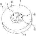
图5A和图5B是根据本文公开主题实施例的说明性轴承的立体图。5A and 5B are perspective views of illustrative bearings, according to embodiments of the herein disclosed subject matter.
虽然公开的主题适合于各种修改和替代形式,但具体实施例已通过示例方式在附图中示出并在下面详细描述。然而,本发明并不旨在将本文公开的主题局限于所描述的特定实施例。相反,本发明旨在涵盖落在本文公开并如所附权利要求限定的主题范围内的所有修改、等同物和替代物。While the disclosed subject matter is susceptible to various modifications and alternative forms, specific embodiments have been shown by way of example in the drawings and described in detail below. The intention, however, is not to limit the herein disclosed subject matter to the particular embodiments described. On the contrary, the invention is intended to cover all modifications, equivalents and alternatives falling within the scope of the subject matter disclosed herein and defined by the appended claims.
如本文中关于值(例如,本文中关于有形物品(例如,产品、库存等)和/或无形物品(例如,数据、货币的电子表示、帐户、信息、物品的一些部分(例如,百分比、分数)、计算、数据模型、动态系统模型、算法、参数等)的特性(例如,尺寸、测量、属性、组件等)和/或其范围使用的辐度、测量和/或定性和/或定量观察的其他程度的术语)使用的,“大约”和“近似”可互换使用以指代值、配置、取向,和/或等同于(或与其相同)所述值、配置、取向的其他特性,和/或等于(或与其相同)值、配置、取向的其他特性和/或合理地接近于所述值、配置、取向的其他特性和/或其他特性,但相关领域中普通技术人员应理解并容易地确定其可由于测量误差;测量和/或制造设备校准中的差异;读取和/或设置测量中的人为错误;鉴于其他测量(例如,与其他事物相关联的测量)为了优化性能和/或结构参数所做的调整;特定的实施方案;由人员、计算装置和/或机器对事物、设置和/或测量进行的不精确的调整和/或操纵;系统公差;控制回路;机器学习;可预见的变化(例如,统计上不重要的变化、混乱的变化、系统和/或模型的不稳定性等);偏好等而引起合理小量的差异。As described herein with respect to values (e.g., herein with respect to tangible items (e.g., products, inventory, etc.) and/or intangible items (e.g., data, electronic representations of currency, accounts, information, ), calculations, data models, dynamic system models, algorithms, parameters, etc.) properties (e.g., dimensions, measurements, properties, components, etc.) and/or extent, measurements, and/or qualitative and/or quantitative observations used in other degrees of the term), "about" and "approximately" are used interchangeably to refer to a value, configuration, orientation, and/or other characteristic that is equivalent to (or identical to) the stated value, configuration, orientation, and/or other characteristics equal to (or the same as) values, configurations, orientations, and/or other characteristics reasonably close to said values, configurations, orientations, and/or other characteristics, but those of ordinary skill in the relevant art will understand and Easily determined which may be due to measurement error; variance in measurement and/or calibration of manufacturing equipment; human error in reading and/or setting measurements; in view of other measurements (e.g., measurements correlated with other things) in order to optimize performance and Adjustments to/or structural parameters; specific implementations; imprecise adjustments and/or manipulations of things, settings, and/or measurements by humans, computing devices, and/or machines; system tolerances; control loops; machine learning ; foreseeable changes (eg, statistically insignificant changes, chaotic changes, system and/or model instability, etc.); preferences, etc. that cause reasonably small differences.
在整个本发明中,术语“上”、“上部”和“向上”及其变化仅出于描述清楚的目的,并且仅旨在指代相对方向(即,要与另一种方向区别开的某个方向),并且并不意味着解释为表示绝对方向。类似地,在整个本发明中,术语“下”、“下部”和“向下”及其变化仅出于描述清楚的目的,并且仅旨在指代至少大致与由术语“上”、“上部”和“向上”及其变化中的一个或多个所指代方向相反的相对方向。Throughout the present invention, the terms "upper", "upper" and "upward" and their variations are used for the purpose of clarity of description only, and are only intended to refer to relative directions (i.e., a certain direction to be distinguished from another direction). directions), and are not meant to be interpreted as indicating absolute directions. Similarly, throughout the present invention, the terms "lower", "lower" and "downward" and variations thereof are for the purpose of clarity of description only, and are only intended to refer to ” and “upward” and variations thereof in a relative direction opposite to the direction indicated by one or more of its variations.
虽然术语“框”在本文中可用于暗示说明性使用的不同元件,但该术语不应解释为表示本文公开的各个框之中或之间的任何要求或特定顺序。类似地,尽管说明性方法可由一个或多个图(例如,流程图、通信流程等)表示,但图不应解释为表示本文公开的各种步骤之中或之间的任何要求或特定顺序。然而,某些实施例可能要求某些步骤之间的某些步骤和/或某些顺序,如本文中可能明确描述的和/或可能根据步骤本身的性质理解的(例如,一些步骤的执行可能取决于前一个步骤的结果)。另外,项目的“集合”、“子集”或“组”(例如,输入、算法、数据值等)可包括一个或多个项目,并且类似地,项目的子集或子组可包括一个或多个项目。“多个”表示一个以上。While the term "block" may be used herein to imply various elements for illustrative use, the term should not be construed to imply any requirement or specific order among or between the various blocks disclosed herein. Similarly, while illustrative methods may be represented by one or more diagrams (eg, flowcharts, communication flows, etc.), the diagrams should not be construed as representing any requirement or specific order among or between the various steps disclosed herein. However, certain embodiments may require certain steps and/or certain orders between certain steps, as may be explicitly described herein and/or may be understood by the nature of the steps themselves (e.g., the performance of some steps may depends on the result of the previous step). Additionally, a "set," "subset," or "group" of items (e.g., inputs, algorithms, data values, etc.) may include one or more items, and similarly, a subset or subgroup of items may include one or multiple items. "Multiple" means more than one.
具体实施方式Detailed ways
本文公开主题的实施例包括轴承设计,其可通过使用润滑来促进减少热量形成并通过防止血液进入到轴承表面上来减少机械血液损伤。包括凹入的凹陷和闭合腔室的轴承设计便于防止血液进入到轴承表面上。润滑可用于在轴承表面提供流体膜以使磨损最小化。根据实施例,可使用任何数量不同类型的润滑剂,诸如,例如,可使用疏水的水不溶性润滑剂(例如,全氟聚醚或聚α-烯烃类的合成润滑剂)。Embodiments of the subject matter disclosed herein include bearing designs that can facilitate reduced heat build-up through the use of lubrication and reduce mechanical blood damage by preventing blood from entering the bearing surfaces. Bearing designs including concave recesses and closed chambers facilitate preventing blood from entering the bearing surfaces. Lubrication can be used to provide a fluid film on the bearing surfaces to minimize wear. Depending on the embodiment, any number of different types of lubricants may be used, such as, for example, hydrophobic water insoluble lubricants (eg, synthetic lubricants of the perfluoropolyether or polyalphaolefin type) may be used.
图1A描绘了根据本文公开主题实施例的说明性经皮机械循环支持装置100(在本文也可互换地称为“血泵”)的一部分的截面侧视图。如图1A所示,循环支持装置100包括设置在马达壳体104内的马达102。马达102配置为驱动叶轮组件106以提供通过装置100的血液流。叶轮组件106设置在叶轮组件壳体108内,该叶轮组件壳体108包括限定在其中的一些出口孔110。根据实施例,马达壳体104和叶轮组件壳体108可彼此整合。在其他实施例中,马达壳体104和叶轮组件壳体108可以是配置为可移除地或永久地连结在一起的单独组件。1A depicts a cross-sectional side view of a portion of an illustrative percutaneous mechanical circulatory support device 100 (also referred to herein interchangeably as a "blood pump") according to an embodiment of the herein disclosed subject matter. As shown in FIG. 1A , the
控制器(未示出)可操作地连结到马达102并配置为控制马达102。控制器在实施例中可设置在马达壳体104内,或者在其他实施例中可设置在壳体104外部(例如,在导管手柄、单独的壳体等内)。在实施例中,控制器可包括多个组件,其中的一个或多个可设置在壳体104内。根据实施例,控制器可以是一个或多个现场可编程门阵列(FPGA)、一个或多个可编程逻辑装置(PLD)、一个或多个复杂PLD(CPLD)、一个或多个定制的专用集成电路(ASIC)、一个或多个专用处理器(例如,微处理器)、一个或多个中央处理单元(CPU)、软件、硬件、固件或这些和/或其他组件的任何组合;包括其或者包括在其中。尽管在本文中以单数指代控制器,但是控制器也可在多个实例中实现,跨多个计算装置分布,在多个虚拟机内实例化等。A controller (not shown) is operatively coupled to the
如图1A所示,叶轮组件106包括驱动轴112和连结至驱动轴112的叶轮114,其中驱动轴112配置为与叶轮114一起旋转。如图所示,驱动轴112至少部分设置在叶轮114内。在实施例中,驱动轴112可由任何数量、不同刚性的材料制成,诸如,例如,钢、钛合金、钴铬合金、镍钛诺、高强度陶瓷等。叶轮组件106还包括连结至驱动轴112并至少部分地围绕驱动轴112的叶轮转子116。叶轮转子116可以是任何类型的磁性转子,其能够由是马达102一部分的定子118驱动。以这种方式,当由马达102中的定子118向叶轮转子116施加磁场时,转子116旋转,从而导致驱动轴112和叶轮114旋转。As shown in FIG. 1A ,
如图所示,叶轮组件沿其取向由驱动轴112保持,驱动轴112在第一端120处由第一轴承组件122保持,在第二端124处由第二轴承组件126保持。根据实施例,第一轴承组件122和第二轴承组件126可包括不同类型的轴承。根据实施例,第一轴承组件122和/或第二轴承组件126可包括润滑,而在其他实施例中,一个和/或另一个可不包括润滑。在本文中关于第一轴承组件122和第二轴承组件126描述了轴承技术的各种实施例。As shown, the impeller assembly is held in its orientation by a
图1B是根据本文公开主题的实施例、图1A中第一轴承组件122的特写视图。第二轴承组件126可包括,例如,轴颈轴承或任何其他类型的合适轴承。如图1B所示,第一轴承组件122包括轴承128,其具有面向叶轮组件106的第一侧130;以及面向马达102的相反的第二侧132。凹入的凹陷134限定在轴承128的第一侧130中。凹入的凹陷134配置为接收驱动轴112的第一端120。如图所示,驱动轴112的第一端120可以是至少部分圆形的,并且在实施例中,可具有与凹入的凹陷134的曲率相对应的曲率。以这种方式,驱动轴112和轴承128之间接触的表面积可尽可能得小,从而减少了任何血液细胞能够在驱动轴112和轴承128的交界处到达其之间的机会。FIG. 1B is a close-up view of the
根据实施例,第一轴承组件122还可包括设置在轴承128的第二侧132和马达102之间的偏置特征136。偏置特征136可具有顺应性,其配置为使得偏置特征136将轴承128偏置在驱动轴112的方向上,从而抵抗由叶轮转子116和定子118之间的吸引力而生成的负载,同时允许足够的柔性以防止轴承128破裂或以其他方式因负载而坏掉。如图所示,轴承128也可由轴承支撑特征138保持在适当位置处,该轴承支撑特征138可整合到马达壳体104、叶轮组件壳体108中,或者可以是连结至马达壳体104和/或叶轮组件壳体108的单独特征。根据实施例,轴承支撑特征138可包括配置为将轴承128保持在其位置处的任何数量、不同类型的特征。例如,轴承支撑特征138可包括多个边缘,配置为接收凸耳或边缘的凹口,配置为与轴承的外围形成过盈配合的边缘等。According to an embodiment, the
图1A和图1B所示的说明性循环支持装置100并不旨在对本发明实施例的使用范围或功能提出任何限制。说明性循环支持装置100也不应解释为对本文所示的任何单个组件或组件组合具有任何依赖性或要求。另外,在实施例中,图1A和1B描绘的各种组件可与本文描绘的其他组件(和/或未示出的组件)中的各种组件相整合,所有这些认为是在本发明的范围内。The illustrative
图2A描绘了根据本文公开主题实施例的说明性经皮机械循环支持装置200的立体图;图2B描绘了根据本文公开主题实施例、图2A中描绘的循环支持装置200的侧剖视图。根据实施例,循环支持装置200和/或其任何数量的各种组件可与图1A和1B中描绘的循环支持装置100的相应组件相同或相似。2A depicts a perspective view of an illustrative percutaneous mechanical
如图2A和2B所示,循环支持装置200包括设置在马达壳体204内的马达202。马达202配置为驱动叶轮组件206以提供通过装置200的血液流。叶轮组件206设置在叶轮组件壳体208内,该叶轮组件壳体208包括限定在其中的许多入口孔210和许多出口孔112。根据实施例,马达壳体204和叶轮组件壳体208可彼此整合。在其他实施例中,马达壳体204和叶轮组件壳体208可以是配置为可移除地或永久地连结在一起的单独组件。控制器(未示出)可操作地连结到马达202并配置为控制马达202。控制器在实施例中可设置在马达壳体204内,或者在其他实施例中可设置在壳体204外部(例如,在导管手柄、单独壳体等内)。在实施例中,控制器可包括多个组件,其中的一个或多个可设置在壳体204内。根据实施例,马达204可以是图1A中所示的马达104,类似于其,包括其或包括在其中。As shown in FIGS. 2A and 2B , the
如图2B所示,叶轮组件206包括驱动轴214和连结至驱动轴214的叶轮216,其中驱动轴214配置为与叶轮216一起旋转。如图所示,驱动轴214至少部分地设置在叶轮216内。在实施例中,驱动轴214可由任何数量、不同刚性的材料制成,诸如,例如,钢、钛合金、钴铬合金、镍钛诺、高强度陶瓷等。叶轮组件206还包括叶轮转子218,其连结至驱动轴214并至少部分地围绕驱动轴214。叶轮转子218可以是任何类型的磁性转子,其能够由为马达202一部分的定子(未示出,但可与图1A和1B中描绘的定子118相同或相似)驱动。以这种方式,当由马达202中的定子向叶轮转子218施加磁场时,转子218旋转,导致驱动轴214和叶轮216旋转。As shown in FIG. 2B ,
如图所示,叶轮组件沿其取向由驱动轴214保持,驱动轴241在第一端220处由第一轴承组件222保持,在第二端224处由第二轴承组件226保持。根据实施例,第一轴承组件222和第二轴承组件226可包括不同类型的轴承。根据实施例,第一轴承组件222和/或第二轴承组件226可包括配置为保持润滑剂的润滑剂室,而在其他实施例中,一个和/或另一个可不包括润滑。在本文中关于第一轴承组件222和第二轴承组件226描述了轴承技术的各种实施例。As shown, the impeller assembly is retained in its orientation by
图2C是根据本文公开主题的实施例、图2B中第一轴承组件222的特写视图。第二轴承组件226可包括,例如,轴颈轴承或任何其他类型的合适轴承。如图2C所示,第一轴承组件222包括轴承228,其具有面向叶轮组件206的第一侧230以及面向马达202的相反的第二侧232。凹入的凹陷234限定在轴承228的第一侧230中。凹入的凹陷234配置为接收驱动轴214的第一端220。如图所示,驱动轴214的第一端220可以是至少部分圆形的,并且在实施例中,凹入的凹陷234的尺寸可设置为刚好适合驱动轴214的第一端22。FIG. 2C is a close-up view of the
如图2C所示,凹入的凹陷234可包括第一部分236和第二部分238,其中第一部分236具有至少大致柱状的形状并从轴承228的第一侧230延伸至轴承228中。第二部分238具有至少大致凹入的形状。在实施例中,第一部分236的尺寸可设置为适合驱动轴214第一端220相应的第一部分240,而第二部分238的尺寸可设置为适合驱动轴214第一端220相应的第二部分242。在实施例中,驱动轴214第一端220的第一部分240可具有大致柱状的形状,驱动轴214第一端220的第二部分242可具有大致凸出的形状。以这种方式,凹陷234的第一部分238可便于将驱动轴214保持在其取向中。As shown in FIG. 2C , the
另外,凹陷凹入的几何形状与驱动轴的圆形端部结合创建了相对较大的轴承表面,从而将轴向负载分布在更大的区域上。驱动轴(并因此为凹入的凹陷)的端部的直径可配置为便于实现期望的性能特性。例如,增加这些直径可导致更高的转速,同时减少轴向应力,从而减少摩擦。根据实施例,轴承组件各个方面的尺寸可基于实施方案、性能、材料等进行选择。Additionally, the recessed geometry combined with the rounded end of the drive shaft creates a relatively large bearing surface, which distributes axial loads over a larger area. The diameter of the end of the drive shaft (and thus the concave recess) can be configured to facilitate desired performance characteristics. For example, increasing these diameters can lead to higher rotational speeds while reducing axial stress, thereby reducing friction. According to an embodiment, dimensions of various aspects of a bearing assembly may be selected based on implementation, performance, material, and the like.
根据实施例,第一轴承组件222还可包括设置在轴承228第二侧232和马达202之间的偏置特征(未示出)。偏置特征可具有顺应性,其配置为使得偏置特征将轴承228偏置在驱动轴214的方向上,从而抵抗由叶轮转子218和定子之间的吸引力而生成的负载,同时允许足够的柔性以防止轴承228破裂或以其他方式因负载而坏掉。如图所示,轴承228也可通过轴承支撑特征244保持在适当位置处,该轴承支撑特征244可整合到马达壳体204、叶轮组件壳体208中,或者可以是连结至马达壳体204和/或叶轮组件壳体208的单独特征。根据实施例,轴承支撑特征244可包括任何数量、不同类型的特征,其配置为将轴承228保持在其位置处。例如,轴承支撑特征244可包括多个边缘,配置为接收凸耳或边缘的凹口,配置为与轴承的外围形成过盈配合的边缘等。According to an embodiment, the
如图所示,轴承组件222还可包括杯形垫圈246,其具有基座248和远离基座248朝向马达202延伸的周壁250,从而形成由基座248的内表面254和周壁250的内表面256界定的腔室252。周壁250可大致垂直于基座248取向。可限定轴孔258通过基座248,从基座248的外表面260延伸至基座248的内表面254;并可配置为接收驱动轴214的一部分。如图所示,轴承228配置为至少部分地设置在腔室252内。As shown, the bearing
另外,润滑剂可设置在腔室内以便保持轴承228及其与驱动轴214的交界面。即,例如,润滑剂室的至少一部分可限定在杯形垫圈246基座248的内表面254、杯形垫圈246周壁250的内表面256和轴承228的第一侧230之间。另外地或替代地,润滑剂室的一部分可限定在轴承内(例如,在轴承228内)。润滑剂可以是适于在血泵中使用的任何类型的疏水润滑剂。例如,在实施例中,但并不旨在限制本发明,润滑剂可以是改性的硅树脂润滑剂,诸如,例如,改性的聚二甲基硅氧烷(PDMS)。在其他实施例中,润滑剂可以是油基润滑剂、合成油、碳基润滑剂等。Additionally, a lubricant may be disposed within the cavity to maintain bearing 228 and its interface with
图2A-2C中所示的说明性循环支持装置200并不旨在对本发明实施例的使用范围或功能提出任何限制。说明性循环支持装置200也不应解释为对本文所示的任何单个组件或组件的组合具有任何依赖性或要求。另外,在实施例中,图2A-2C中描绘的各种组件可与本文描绘的其他组件(和/或未示出的组件)中的各种组件相整合,所有这些认为是在本发明的范围内。The illustrative
图3描绘了根据本文公开主题实施例、具有叶轮组件301的说明性循环支持装置300的侧剖视图。根据实施例,循环支持装置300和/或其任何数量的各种组件可与图1A和1B中描绘的循环支持装置100和/或图2A-2C中描绘的循环支持装置200的相应组件相同或相似。3 depicts a side cross-sectional view of an illustrative
如图3所示,叶轮组件301设置在叶轮组件壳体302内,该叶轮组件壳体302包括限定在其中的许多出口孔304。叶轮组件301包括驱动轴306和连结至驱动轴306的叶轮308,其中驱动轴306配置为与叶轮308一起旋转。如图所示,驱动轴306至少部分地设置在叶轮308内。在实施例中,驱动轴306可由任何数量、不同刚性的材料制成,诸如,例如,钢、钛合金、钴铬合金、镍钛诺、高强度陶瓷等。叶轮组件308还包括叶轮转子310,其连结至驱动轴306并至少部分地围绕驱动轴306。叶轮转子310可以是任何类型的磁性转子,其能够由为马达一部分的定子(未示出,但可与图1A和1B中描绘的定子118相同或相似)驱动。以这种方式,当由马达中的定子向叶轮转子310施加磁场时,转子310旋转,导致驱动轴306和叶轮308旋转。As shown in FIG. 3 ,
如图所示,叶轮组件301沿其取向由驱动轴306保持,驱动轴306在第一端312处由第一轴承组件314保持,在第二端(未示出)处由第二轴承组件(未示出)保持。根据实施例,第一轴承组件314和第二轴承组件可包括不同类型的轴承。根据实施例,第一轴承组件314和/或第二轴承组件可包括配置为保持润滑剂的润滑剂室。第一轴承组件314包括轴承316,其具有面向叶轮组件301的第一侧318;以及面向马达的相反的第二侧320。凹入的凹陷322限定在轴承316的第一侧318中。凹入的凹陷322配置为接收驱动轴306的第一端312,并且在实施例中可以类似于图1B中描绘的凹入的凹陷134和/或图2C中描绘的凹入的凹陷234的方式进行配置。如图所示,驱动轴214的第一端312可以类似于图1A和1B中描绘的驱动轴112的第一端120和/或图2B-2C中描绘的驱动轴214的第一端220的方式进行配置。根据实施例,第一轴承组件314也可包括设置在轴承316的第二侧320和马达之间的偏置特征(未示出)。As shown, the
如图所示,轴承组件314也可包括杯形垫圈324或其他类似的盆状结构,其具有基座326和远离基座326朝向叶轮组件301延伸的周壁328,从而形成由基座326的内表面332和周壁328的内表面334界定的腔室330。如图所示,轴承316配置为至少部分地设置在腔室330内。覆盖件336可邻近轴承316的第一侧318设置,并包括配置为接收驱动轴306的一部分的轴孔338。在实施例中,例如,覆盖件336可以是石墨、聚合物等的层。As shown, the bearing
如图3中进一步所示,轴承组件314包括配置为保持润滑剂的润滑剂室。润滑剂室可包括限定在轴承316的第二侧320中的至少一个通道340。在实施例中,通道或多个通道穿过凹陷322。根据实施例,轴承316可包括限定在其中的两个或更多个通道340。如可从图3看到的,基座326内表面332的至少一部分可形成润滑剂室的边界。As further shown in FIG. 3 , bearing
图3中所示的说明性循环支持装置300并不旨在对本发明实施例的使用范围或功能提出任何限制。说明性循环支持装置300也不应解释为对本文所示的任何单个组件或组件组合具有任何依赖性或要求。另外,在实施例中,图3中描绘的各种组件可与本文描绘的其他组件(和/或未示出的组件)中的各种组件相整合,所有这些认为是在本发明的范围内。The illustrative
图4描绘了根据本文公开主题实施例、具有叶轮组件402的说明性循环支持装置400的侧剖视图。根据实施例,循环支持装置400和/或其任何数量的各种组件可与图1A和1B中描绘的循环支持装置100,图2A-2C中描绘的循环支持装置200和/或图3中描绘的循环支持装置300的相应组件相同或相似。在实施例中,图4中描绘的循环支持装置400的部分是叶轮组件与邻近马达的端部相对的端部有关的部分。即,例如,图4中描绘的轴承组件404可以是图1A中描绘的轴承组件126和/或图2B中描绘的轴承组件226,与其相似和/或以其他方式与其相对应。在实施例中,替代地或另外地,可使用轴承组件404的实施方式作为图1A和1B中描绘的轴承组件122,图2B和2C中描绘的轴承组件222,图3中描绘的轴承组件314等。4 depicts a side cross-sectional view of an illustrative
如图4所示,叶轮组件402设置在叶轮组件壳体406内,该叶轮组件壳体406包括限定在其中的许多孔(未示出)。叶轮组件402包括驱动轴408和连结至驱动轴408的叶轮410,其中驱动轴408配置为与叶轮410一起旋转。如图所示,驱动轴408至少部分地设置在叶轮410内。在实施例中,驱动轴408可由任何数量、不同刚性的材料制成,诸如,例如,钢、钛合金、钴铬合金、镍钛诺、高强度陶瓷等。As shown in FIG. 4 ,
叶轮组件402沿其取向由驱动轴408保持,驱动轴408在第一端(未示出)处由第一轴承组件(未示出)保持,在第二端412处由轴承组件保持。根据实施例,第一轴承组件和第二轴承组件404可包括不同类型的轴承。根据实施例,第一轴承组件和/或第二轴承组件404可包括配置为保持润滑剂的润滑剂室。轴承组件404包括设置在驱动轴408的端部412中的柱状轴承414。轴承414包括背离叶轮的第一内表面416和远离第一内表面延伸的第二内表面418。根据实施例,第二内表面418可大致垂直于第一内表面416取向。The
如图4所示,柱状轴承设置在驱动轴408和固定轴安装销420的交叉点处。轴安装销可由任何数量的不同材料制成。例如,在一些实施例中,轴安装销420可由与驱动轴408相同的材料制成。轴安装销420可连结至销支撑件422。驱动轴408配置为相对于固定轴安装销420旋转。为了促进减小摩擦并保持轴承组件404,轴承组件404可包括润滑剂室424。润滑剂室424可限定在轴承414的第一内表面416和固定轴安装销420的外表面426之间。润滑剂室424可进一步由轴承414的第二内表面418的至少一部分界定。As shown in FIG. 4 , cylindrical bearings are provided at the intersection of the
图4中所示的说明性循环支持装置400并不旨在对本发明实施例的使用范围或功能提出任何限制。说明性循环支持装置400也不应解释为对本文所示的任何单个组件或组件组合具有任何依赖性或要求。另外,在实施例中,图4中描绘的各种组件可与本文描绘的其他组件(和/或未示出的组件)中的各种组件相整合,所有这些认为是在本发明的范围内。The illustrative
如上所述,润滑剂室的一部分可限定在轴承内。图5A和5B是根据本文公开主题实施例的说明性轴承500的立体图。根据实施例,轴承500可以是图1A和1B中描绘的轴承122,图2A-2C中描绘的轴承222,图3中描绘的轴承322等,或与其相似。在实施例中,轴承500包括配置为面向叶轮组件的第一侧502,以及配置为面向马达的相反的第二侧504。凹入的凹陷506限定在轴承500的第一侧230中。凹入的凹陷506配置为接收驱动轴的端部。如本文讨论的,驱动轴的端部可以是至少部分圆形的,并且在实施例中,凹入的凹陷506的尺寸可设置为刚好适合驱动轴的端部。As noted above, a portion of the lubricant chamber may be defined within the bearing. 5A and 5B are perspective views of an
如图所示,凹入的凹陷500可包括第一部分508和第二部分510,其中第一部分508具有至少大致柱状,并从轴承500的第一侧502延伸至轴承500中。第二部分510具有至少大致凹入的形状。在实施例中,第一部分508的尺寸可设置为适合驱动轴端部相应的第一部分,而第二部分510的尺寸可设置为适合驱动轴端部相应的第二部分。在实施例中,驱动轴端部的第一部分可具有大致柱状,并且驱动轴端部的第二部分可具有大致凸出的形状。以这种方式,凹陷506的第一部分508可便于将驱动轴保持在其取向中。As shown, the
如进一步所示,在轴承500的第二侧504中限定了两个通道512。根据实施例,轴承500可包括任何数量的通道(例如,1、2、3、4、5等),其具有任何数量的不同深度、宽度等。例如,在实施例中,通道并不延伸通过周壁516的外表面514。在实施例中,轴承500可包括具有不同尺寸的多个通道。例如,轴承500可包括微通道(例如,基本上比通道512更窄且更浅的通道,诸如,例如,达至少5倍),其限定在凹入的凹陷的上表面518中。根据实施例,使用具有限定在其中的用于润滑剂室的通道的轴承可便于使用更薄的轴承,从而使得叶轮组件的转子能够更接近马达的定子,这能够增加扭矩和效率。As further shown, two
图5A和5B中所示的轴承500并不旨在对本发明实施例的使用范围或功能提出任何限制。说明性轴承500也不应解释为对本文所示的任何单个组件或组件组合具有任何依赖性或要求。另外,在实施例中,图5A和5B中描绘的各种组件可与本文描绘的其他组件(和/或未示出的组件)中的各种组件相整合,所有这些认为是在本发明的范围内。The bearing 500 shown in Figures 5A and 5B is not intended to present any limitation as to the scope of use or functionality of embodiments of the present invention. Neither should the
在不脱离本发明范围的情况下,可对所讨论的示例性实施例进行各种修改和添加。例如,虽然上述实施例涉及特定特征,但本发明的范围还包括具有不同特征组合的实施例以及不包括所有所述特征的实施例。因此,本发明的范围旨在包括落入权利要求范围内的所有这样的替代物、修改和变化,及其所有等同物。Various modifications and additions may be made to the exemplary embodiments discussed without departing from the scope of the present invention. For example, while the embodiments described above refer to certain features, the scope of the invention also includes embodiments having different combinations of features and embodiments that do not include all of the described features. Accordingly, the scope of the present invention is intended to embrace all such alternatives, modifications and changes, and all equivalents thereof, which fall within the scope of the claims.
Claims (13)
Priority Applications (1)
| Application Number | Priority Date | Filing Date | Title |
|---|---|---|---|
| CN202310671702.1ACN116804421A (en) | 2018-10-18 | 2019-10-18 | blood pump shaft bearing |
Applications Claiming Priority (3)
| Application Number | Priority Date | Filing Date | Title |
|---|---|---|---|
| US201862747346P | 2018-10-18 | 2018-10-18 | |
| US62/747,346 | 2018-10-18 | ||
| PCT/US2019/056956WO2020081944A1 (en) | 2018-10-18 | 2019-10-18 | Blood pump shaft bearing |
Related Child Applications (1)
| Application Number | Title | Priority Date | Filing Date |
|---|---|---|---|
| CN202310671702.1ADivisionCN116804421A (en) | 2018-10-18 | 2019-10-18 | blood pump shaft bearing |
Publications (2)
| Publication Number | Publication Date |
|---|---|
| CN112689716A CN112689716A (en) | 2021-04-20 |
| CN112689716Btrue CN112689716B (en) | 2023-06-30 |
Family
ID=68468849
Family Applications (2)
| Application Number | Title | Priority Date | Filing Date |
|---|---|---|---|
| CN202310671702.1APendingCN116804421A (en) | 2018-10-18 | 2019-10-18 | blood pump shaft bearing |
| CN201980059651.9AActiveCN112689716B (en) | 2018-10-18 | 2019-10-18 | Blood pump shaft bearing |
Family Applications Before (1)
| Application Number | Title | Priority Date | Filing Date |
|---|---|---|---|
| CN202310671702.1APendingCN116804421A (en) | 2018-10-18 | 2019-10-18 | blood pump shaft bearing |
Country Status (4)
| Country | Link |
|---|---|
| US (3) | US11565103B2 (en) |
| EP (1) | EP3867541B1 (en) |
| CN (2) | CN116804421A (en) |
| WO (1) | WO2020081944A1 (en) |
Families Citing this family (37)
| Publication number | Priority date | Publication date | Assignee | Title |
|---|---|---|---|---|
| EP4290081A3 (en) | 2015-09-25 | 2024-02-21 | Procyrion, Inc. | Non-occluding intravascular blood pump providing reduced hemolysis |
| DE102018201030B4 (en) | 2018-01-24 | 2025-10-16 | Kardion Gmbh | Magnetic dome element with magnetic bearing function |
| CN112004563B (en) | 2018-02-01 | 2024-08-06 | 施菲姆德控股有限责任公司 | Intravascular blood pump and methods of use and manufacture |
| DE102018207575A1 (en) | 2018-05-16 | 2019-11-21 | Kardion Gmbh | Magnetic face turning coupling for the transmission of torques |
| DE102018207611A1 (en) | 2018-05-16 | 2019-11-21 | Kardion Gmbh | Rotor bearing system |
| DE102018208539A1 (en) | 2018-05-30 | 2019-12-05 | Kardion Gmbh | A motor housing module for sealing an engine compartment of a motor of a cardiac assist system and cardiac assistance system and method for mounting a cardiac assist system |
| DE102018208541A1 (en) | 2018-05-30 | 2019-12-05 | Kardion Gmbh | Axial pump for a cardiac assist system and method of making an axial pump for a cardiac assist system |
| DE102018208538A1 (en) | 2018-05-30 | 2019-12-05 | Kardion Gmbh | Intravascular blood pump and process for the production of electrical conductors |
| DE102018208550A1 (en) | 2018-05-30 | 2019-12-05 | Kardion Gmbh | A lead device for directing blood flow to a cardiac assist system, cardiac assist system, and method of making a lead device |
| DE102018210058A1 (en) | 2018-06-21 | 2019-12-24 | Kardion Gmbh | Stator blade device for guiding the flow of a fluid flowing out of an outlet opening of a heart support system, heart support system with stator blade device, method for operating a stator blade device and manufacturing method |
| DE102018210076A1 (en) | 2018-06-21 | 2019-12-24 | Kardion Gmbh | Method and device for detecting a state of wear of a cardiac support system, method and device for operating a cardiac support system and cardiac support system |
| DE102018211327A1 (en) | 2018-07-10 | 2020-01-16 | Kardion Gmbh | Impeller for an implantable vascular support system |
| DE102018212153A1 (en) | 2018-07-20 | 2020-01-23 | Kardion Gmbh | Inlet line for a pump unit of a cardiac support system, cardiac support system and method for producing an inlet line for a pump unit of a cardiac support system |
| CN112654389A (en) | 2018-08-07 | 2021-04-13 | 开迪恩有限公司 | Bearing device for a cardiac support system and method for flushing an intermediate space in a bearing device for a cardiac support system |
| EP3867541B1 (en) | 2018-10-18 | 2025-01-08 | Boston Scientific Scimed Inc. | Blood pump |
| US12171994B2 (en) | 2019-09-11 | 2024-12-24 | Boston Scientific Scimed, Inc. | Reduced thrombosis blood pump with washout bearing |
| WO2021067691A1 (en)* | 2019-10-03 | 2021-04-08 | Boston Scientific Scimed Inc | Reduced thrombosis blood pump |
| IL293625A (en) | 2019-12-03 | 2022-08-01 | Procyrion Inc | blood pumps |
| EP4072650A4 (en) | 2019-12-11 | 2024-01-10 | Shifamed Holdings, LLC | Descending aorta and vena cava blood pumps |
| WO2021119413A1 (en) | 2019-12-13 | 2021-06-17 | Procyrion, Inc. | Support structures for intravascular blood pumps |
| DE102020102474A1 (en) | 2020-01-31 | 2021-08-05 | Kardion Gmbh | Pump for conveying a fluid and method for manufacturing a pump |
| EP3884969A1 (en)* | 2020-03-27 | 2021-09-29 | Abiomed Europe GmbH | Blood pump |
| NL2025395B1 (en)* | 2020-04-22 | 2021-10-28 | P Bekkers Holding B V | High pressure nozzle |
| CN119327026A (en)* | 2020-07-31 | 2025-01-21 | 深圳核心医疗科技股份有限公司 | Interventional ventricular assist device |
| US20230149691A1 (en)* | 2021-11-16 | 2023-05-18 | Boston Scientific Scimed Inc. | Percutaneous circulatory support system facilitating reduced hemolysis |
| CN114796849A (en)* | 2022-02-23 | 2022-07-29 | 深圳核心医疗科技有限公司 | Blood pump and driving device thereof |
| CN115282470B (en)* | 2022-07-08 | 2023-08-18 | 深圳核心医疗科技股份有限公司 | Drives and blood pumps |
| CN115006717A (en)* | 2022-07-08 | 2022-09-06 | 深圳核心医疗科技有限公司 | Drives and blood pumps |
| EP4477249A4 (en)* | 2022-07-08 | 2025-10-08 | Shenzhen Core Medical Tech Co Ltd | DRIVE MECHANISM AND BLOOD PUMP |
| CN115282467B (en)* | 2022-07-08 | 2024-02-23 | 深圳核心医疗科技股份有限公司 | Driving mechanism and blood pump |
| CN115025387B (en)* | 2022-07-08 | 2023-05-30 | 深圳核心医疗科技股份有限公司 | Driving device and blood pump |
| CN115068811A (en)* | 2022-07-08 | 2022-09-20 | 深圳核心医疗科技有限公司 | Drive device and blood pump |
| CN115300786A (en)* | 2022-07-26 | 2022-11-08 | 深圳核心医疗科技有限公司 | Drives and blood pumps |
| CN117282020A (en)* | 2022-08-15 | 2023-12-26 | 深圳核心医疗科技股份有限公司 | Driving device and blood pump |
| CN115364366A (en)* | 2022-08-30 | 2022-11-22 | 深圳核心医疗科技有限公司 | Drive mechanism and blood pump |
| CN115253063A (en)* | 2022-09-02 | 2022-11-01 | 深圳核心医疗科技有限公司 | Drive mechanism and blood pump |
| CN115382092A (en)* | 2022-09-05 | 2022-11-25 | 深圳核心医疗科技有限公司 | Drives and blood pumps |
Citations (3)
| Publication number | Priority date | Publication date | Assignee | Title |
|---|---|---|---|---|
| JP2005220777A (en)* | 2004-02-04 | 2005-08-18 | Matsushita Electric Ind Co Ltd | Vane rotary vacuum pump |
| CN107349484A (en)* | 2017-08-24 | 2017-11-17 | 清华大学 | Suspension rotor blood pump and pumping system |
| CN107921187A (en)* | 2015-08-04 | 2018-04-17 | 阿比奥梅德欧洲股份有限公司 | Blood pump |
Family Cites Families (39)
| Publication number | Priority date | Publication date | Assignee | Title |
|---|---|---|---|---|
| US3265452A (en)* | 1965-05-04 | 1966-08-09 | Mechanical Tech Inc | Bearings |
| GB2101695B (en)* | 1981-07-10 | 1985-03-06 | British Gas Corp | Improvements in or relating to lubricated bearings |
| US4817586A (en) | 1987-11-24 | 1989-04-04 | Nimbus Medical, Inc. | Percutaneous bloom pump with mixed-flow output |
| US4895557A (en) | 1987-12-07 | 1990-01-23 | Nimbus Medical, Inc. | Drive mechanism for powering intravascular blood pumps |
| US5017103A (en)* | 1989-03-06 | 1991-05-21 | St. Jude Medical, Inc. | Centrifugal blood pump and magnetic coupling |
| DE69027525T2 (en)* | 1990-04-09 | 1997-01-16 | St. Jude Medical, Inc., St. Paul, Minn. | Centrifugal blood pump and motor drive |
| US5211546A (en)* | 1990-05-29 | 1993-05-18 | Nu-Tech Industries, Inc. | Axial flow blood pump with hydrodynamically suspended rotor |
| US7077822B1 (en) | 1994-02-09 | 2006-07-18 | The University Of Iowa Research Foundation | Stereotactic hypothalamic obesity probe |
| US5588812A (en)* | 1995-04-19 | 1996-12-31 | Nimbus, Inc. | Implantable electric axial-flow blood pump |
| US5568976A (en)* | 1995-12-04 | 1996-10-29 | J.C. Pardo & Sons | Idler bearing mount for mounting of inclined agitators |
| US6186665B1 (en)* | 1999-01-26 | 2001-02-13 | Nimbus, Inc. | Motor rotor bearing assembly for a blood pump |
| WO2003103534A2 (en) | 2002-06-01 | 2003-12-18 | Walid Aboul-Hosn | Percutaneously introduced blood pump and related methods |
| AU2006255059A1 (en) | 2005-06-06 | 2006-12-14 | Foster-Miller, Inc. | Blood pump |
| CN102380135A (en) | 2006-03-23 | 2012-03-21 | 宾州研究基金会 | Heart assist device with expandable impeller pump |
| CN101015716A (en)* | 2007-03-09 | 2007-08-15 | 清华大学 | Implanted non-contact minisize axial-flow blood pump |
| US8489190B2 (en) | 2007-10-08 | 2013-07-16 | Ais Gmbh Aachen Innovative Solutions | Catheter device |
| US8439859B2 (en) | 2007-10-08 | 2013-05-14 | Ais Gmbh Aachen Innovative Solutions | Catheter device |
| US9199020B2 (en) | 2007-11-01 | 2015-12-01 | Abiomed, Inc. | Purge-free miniature rotary pump |
| EP2246078A1 (en) | 2009-04-29 | 2010-11-03 | ECP Entwicklungsgesellschaft mbH | Shaft assembly with a shaft which moves within a fluid-filled casing |
| CN102481398A (en) | 2009-07-01 | 2012-05-30 | 宾夕法尼亚州研究基金会 | Blood pump with expandable cannula |
| US8597170B2 (en) | 2011-01-05 | 2013-12-03 | Thoratec Corporation | Catheter pump |
| WO2012094641A2 (en) | 2011-01-06 | 2012-07-12 | Thoratec Corporation | Percutaneous heart pump |
| WO2012094535A2 (en) | 2011-01-06 | 2012-07-12 | Thoratec Corporation | Percutaneous heart pump |
| US8849398B2 (en) | 2011-08-29 | 2014-09-30 | Minnetronix, Inc. | Expandable blood pump for cardiac support |
| US9162017B2 (en) | 2011-08-29 | 2015-10-20 | Minnetronix, Inc. | Expandable vascular pump |
| DE102012202411B4 (en) | 2012-02-16 | 2018-07-05 | Abiomed Europe Gmbh | INTRAVASAL BLOOD PUMP |
| DE102012203615B4 (en)* | 2012-03-07 | 2013-11-21 | Hanning Elektro-Werke Gmbh & Co. Kg | pump |
| US8777832B1 (en) | 2013-03-14 | 2014-07-15 | The University Of Kentucky Research Foundation | Axial-centrifugal flow catheter pump for cavopulmonary assistance |
| US9144638B2 (en)* | 2013-03-14 | 2015-09-29 | Thoratec Corporation | Blood pump rotor bearings |
| DE102013208038B4 (en) | 2013-05-02 | 2016-09-08 | Michael Siegenthaler | Catheter-based cardiac assist system |
| US20160045654A1 (en) | 2014-08-14 | 2016-02-18 | Medibotics Llc | Implanted Extracardiac Device for Circulatory Assistance |
| EP2865397A1 (en) | 2013-10-22 | 2015-04-29 | Berlin Heart GmbH | Method for operating a pump device and pump device |
| US9308305B2 (en) | 2014-06-18 | 2016-04-12 | Ch Biomedical (Usa) Inc. | Implantable blood pump with integrated controller |
| US9345824B2 (en) | 2014-07-07 | 2016-05-24 | Assistocor Gmbh & Co Kg | Ventricular assist device |
| EP4414020A3 (en)* | 2015-03-18 | 2024-10-30 | Abiomed Europe GmbH | Blood pump |
| US9907890B2 (en) | 2015-04-16 | 2018-03-06 | Tc1 Llc | Catheter pump with positioning brace |
| EP3222301B1 (en) | 2016-03-23 | 2018-05-09 | Abiomed Europe GmbH | Blood pump |
| CN207568879U (en)* | 2017-09-21 | 2018-07-03 | 深圳核心医疗器械有限公司 | A kind of device of fast verification blood pump pressure flow curve |
| EP3867541B1 (en) | 2018-10-18 | 2025-01-08 | Boston Scientific Scimed Inc. | Blood pump |
- 2019
- 2019-10-18EPEP19798470.1Apatent/EP3867541B1/enactiveActive
- 2019-10-18WOPCT/US2019/056956patent/WO2020081944A1/ennot_activeCeased
- 2019-10-18USUS16/657,246patent/US11565103B2/enactiveActive
- 2019-10-18CNCN202310671702.1Apatent/CN116804421A/enactivePending
- 2019-10-18CNCN201980059651.9Apatent/CN112689716B/enactiveActive
- 2023
- 2023-01-11USUS18/095,738patent/US12290676B2/enactiveActive
- 2025
- 2025-04-07USUS19/171,672patent/US20250229078A1/enactivePending
Patent Citations (3)
| Publication number | Priority date | Publication date | Assignee | Title |
|---|---|---|---|---|
| JP2005220777A (en)* | 2004-02-04 | 2005-08-18 | Matsushita Electric Ind Co Ltd | Vane rotary vacuum pump |
| CN107921187A (en)* | 2015-08-04 | 2018-04-17 | 阿比奥梅德欧洲股份有限公司 | Blood pump |
| CN107349484A (en)* | 2017-08-24 | 2017-11-17 | 清华大学 | Suspension rotor blood pump and pumping system |
Also Published As
| Publication number | Publication date |
|---|---|
| CN112689716A (en) | 2021-04-20 |
| US11565103B2 (en) | 2023-01-31 |
| US20200121835A1 (en) | 2020-04-23 |
| US20250229078A1 (en) | 2025-07-17 |
| CN116804421A (en) | 2023-09-26 |
| US12290676B2 (en) | 2025-05-06 |
| EP3867541B1 (en) | 2025-01-08 |
| US20230158290A1 (en) | 2023-05-25 |
| WO2020081944A1 (en) | 2020-04-23 |
| EP3867541A1 (en) | 2021-08-25 |
Similar Documents
| Publication | Publication Date | Title |
|---|---|---|
| CN112689716B (en) | Blood pump shaft bearing | |
| US11666748B2 (en) | Hybrid bearing seal for use in blood pump | |
| JP7087154B2 (en) | Blood pump | |
| US20200306434A1 (en) | Mechanical circulatory support pump drive with corrosion protection | |
| US11577067B2 (en) | Reduced thrombosis blood pump | |
| JP6752155B2 (en) | Heart pump | |
| US9144638B2 (en) | Blood pump rotor bearings | |
| US12171994B2 (en) | Reduced thrombosis blood pump with washout bearing | |
| JP6134702B2 (en) | Centrifugal pump and centrifugal pump manufacturing method | |
| US20240001103A1 (en) | Flow enhancement for circulatory support device | |
| CN105324139A (en) | Impellers of centrifugal pump units | |
| JP2016044673A (en) | Dynamic pressure bearing pump | |
| CN104283363B (en) | Bearing mechanism, motor and blower fan | |
| JP7628620B2 (en) | Magnetic propulsion and bearings for hemodynamic support pumps. | |
| JP6497057B2 (en) | Centrifugal pump | |
| US11519413B2 (en) | Optimizing pumping of variable viscosities via microtextured miniaturized tesla pump | |
| CN108496007A (en) | Vane pump | |
| KR20190131587A (en) | Journal bearing with improved efficiency | |
| JP5993274B2 (en) | Pump device with impeller | |
| WO2019199222A1 (en) | A pump housing device for a fluid pump, and a fluid pump | |
| CN107588042B (en) | Fan blade structure and its rotor group | |
| WO2008053818A1 (en) | Helical flow pump for blood |
Legal Events
| Date | Code | Title | Description |
|---|---|---|---|
| PB01 | Publication | ||
| PB01 | Publication | ||
| SE01 | Entry into force of request for substantive examination | ||
| SE01 | Entry into force of request for substantive examination | ||
| GR01 | Patent grant | ||
| GR01 | Patent grant |