CN112684511A - Linear positioning method based on two-point magnetic gradient full tensor - Google Patents
Linear positioning method based on two-point magnetic gradient full tensorDownload PDFInfo
- Publication number
- CN112684511A CN112684511ACN202110013391.0ACN202110013391ACN112684511ACN 112684511 ACN112684511 ACN 112684511ACN 202110013391 ACN202110013391 ACN 202110013391ACN 112684511 ACN112684511 ACN 112684511A
- Authority
- CN
- China
- Prior art keywords
- point
- magnetic gradient
- magnetic
- full tensor
- formula
- Prior art date
- Legal status (The legal status is an assumption and is not a legal conclusion. Google has not performed a legal analysis and makes no representation as to the accuracy of the status listed.)
- Granted
Links
Images

Landscapes
- Measuring Magnetic Variables (AREA)
Abstract
Translated fromChinese
Description
Translated fromChinese技术领域technical field
本发明涉及磁探测领域,尤其是涉及一种基于两点磁梯度全张量的线性定位方法。The invention relates to the field of magnetic detection, in particular to a linear positioning method based on a two-point magnetic gradient full tensor.
背景技术Background technique
磁探测是研究磁性目标相关信息的重要技术手段,特别是在识别定位深海或地下磁性掩埋物方面,磁异常探测技术具有更好的主动性和隐蔽性。采用单个观测点实现的单点磁梯度全张量磁性目标定位方法存在受地磁影响大的问题。现有技术中也存在一些采用两个或多个观测点实现定位的方法,现有的两点或多点的定位方法虽然减小了地磁场的影响,却基本都面临着非线性方程组求解的问题,求解过程复杂、无法得到解析最优解。Magnetic detection is an important technical means to study the relevant information of magnetic targets, especially in identifying and locating deep-sea or underground magnetic buried objects, magnetic anomaly detection technology has better initiative and concealment. The single-point magnetic gradient full tensor magnetic target localization method using a single observation point has the problem of being greatly affected by the geomagnetism. There are also some methods of using two or more observation points to achieve positioning in the prior art. Although the existing two or more point positioning methods reduce the influence of the geomagnetic field, they are basically faced with the problem of solving nonlinear equations. The solution process is complicated and the analytical optimal solution cannot be obtained.
发明内容SUMMARY OF THE INVENTION
为解决上述背景技术中提出的问题,本发明的目的在于提供一种基于两点磁梯度全张量的线性定位方法。In order to solve the problems raised in the above background art, the purpose of the present invention is to provide a linear positioning method based on the full tensor of two-point magnetic gradients.
为实现上述目的,本发明采取的技术方案为:To achieve the above object, the technical scheme adopted in the present invention is:
一种基于两点磁梯度全张量的线性定位方法,包括如下步骤:A linear positioning method based on two-point magnetic gradient full tensor, comprising the following steps:
S1,以空间中任意一点为原点建立空间直角坐标系,确定第一观测点与第二观测点的坐标,得到待定位目标点的定位公式:S1, establish a space rectangular coordinate system with any point in the space as the origin, determine the coordinates of the first observation point and the second observation point, and obtain the positioning formula of the target point to be located:

其中,
式中,


S2,分别测量两个观测点的磁梯度全张量G1、G2;S2, measure the magnetic gradient full tensors G1 and G2 of the two observation points respectively;
S3,将步骤S2中测得的数据代入步骤S1中,计算得到待定位目标点的定位数据。S3: Substitute the data measured in step S2 into step S1, and calculate the positioning data of the target point to be positioned.
在一些实施例中,步骤S1中,得到待定位目标点的定位公式的具体步骤如下:In some embodiments, in step S1, the specific steps for obtaining the positioning formula of the target point to be positioned are as follows:
对于任意点(x,y,z)的磁场矢量

在磁偶极子空间任意一点的磁场

其中,μ0为真空的磁导率,r为磁性目标到探测点的位置矢量


设在位置矢量


根据公式(4)和(5)可得According to formulas (4) and (5), we can get

在公式(6)中In formula (6)

将公式(7)代入公式(5)可得Substitute formula (7) into formula (5) to get

在公式(8)中

因此

根据公式(8)和(10)可得:According to formulas (8) and (10), we can get:

将目标点到第一观测点的位置矢量表示为


由公式(11)可得According to formula (11), we can get


由公式(12)可得According to formula (12), we can get

根据公式(12)、(13)、(14)、(15)即可得到式(2):According to formulas (12), (13), (14), (15), formula (2) can be obtained:

进一步便可得到式(1):Further formula (1) can be obtained:

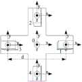
在一些实施例中,步骤S2中,采用四个对称设置的磁通门传感器构成十字形磁梯度全张量测量系统,利用该系统测量磁场数据,并根据测得的数据分别计算得出第一观测点和第二观测点的磁梯度全张量G1、G2。In some embodiments, in step S2, four symmetrically arranged fluxgate sensors are used to form a cross-shaped magnetic gradient full tensor measurement system, the system is used to measure magnetic field data, and the first The magnetic gradient full tensors G1 and G2 of the observation point and the second observation point.
在一些实施例中,步骤S2中,具体根据如下步骤测量两个观测点的磁梯度全张量:In some embodiments, in step S2, the magnetic gradient full tensor of the two observation points is measured according to the following steps:
根据麦克斯韦方程,有According to Maxwell's equations, we have


由公式(16)和(17)可得From equations (16) and (17) we can get

因此公式(3)可表示为:So formula (3) can be expressed as:

将待测点放置在十字形磁梯度全张量测量系统的几何中心处,则待测点的磁梯度全张量可表示为:If the point to be measured is placed at the geometric center of the cross-shaped magnetic gradient full tensor measurement system, the magnetic gradient full tensor of the point to be measured can be expressed as:

其中,d表示每两个相对磁通门的基线距离,Bix、Biy、Biz分别表示第i个磁通门传感器测得的磁场强度的三个方向的分量,i=1、2、3、4,且四个磁通门传感器依次逆时针排列;Among them, d represents the baseline distance of each two relative fluxgates, Bix , Biy , and Biz respectively represent the components of the magnetic field intensity measured by the ith fluxgate sensor in three directions, i=1, 2, 3, 4, and the four fluxgate sensors are arranged counterclockwise in turn;
分别将第一观测点和第二观测点放置在十字形磁梯度全张量测量系统的几何中心处,并利用公式(20)即可分别测得第一观测点和第二观测点的磁梯度全张量G1、G2。Place the first observation point and the second observation point at the geometric center of the cross-shaped magnetic gradient full tensor measurement system, and use the formula (20) to measure the magnetic gradient of the first observation point and the second observation point respectively. Full tensors G1 , G2 .
与现有技术相比,本发明的有益效果是:Compared with the prior art, the beneficial effects of the present invention are:
本发明提供的基于两点磁梯度全张量的线性定位方法,可以根据两点磁梯度全张量以及两点的相对位置实现对目标点的定位,期间不需要测量地磁场值,减小了地磁场噪声所产生的定位误差,并且采用线性方法完成解算,求解过程简便,可以直接得出解析解。The linear positioning method based on the two-point magnetic gradient full tensor provided by the present invention can realize the positioning of the target point according to the two-point magnetic gradient full tensor and the relative position of the two points, and the geomagnetic field value does not need to be measured during the period, reducing the need for The positioning error caused by the geomagnetic field noise, and the linear method is used to complete the solution, the solution process is simple, and the analytical solution can be directly obtained.
附图说明Description of drawings
图1为利用本发明提供的基于两点磁梯度全张量的线性定位方法时建立的空间直角坐标系的示意图;Fig. 1 is the schematic diagram of the space Cartesian coordinate system established when utilizing the linear positioning method based on the two-point magnetic gradient full tensor provided by the present invention;
图2为十字形磁梯度全张量测量系统模型示意图。FIG. 2 is a schematic diagram of a cross-shaped magnetic gradient full tensor measurement system model.
具体实施方式Detailed ways
为使本发明实现的技术手段、创作特征、达成目的与功效易于明白了解,下面结合附图和具体实施方式,进一步阐述本发明是如何实施的。In order to make the technical means, creative features, achievement goals and effects realized by the present invention easy to understand, how the present invention is implemented is further described below with reference to the accompanying drawings and specific embodiments.
本发明提供了一种基于两点磁梯度全张量的线性定位方法,包括如下步骤:The invention provides a linear positioning method based on two-point magnetic gradient full tensor, comprising the following steps:
S1,如图1所示,以空间中任意一点为原点建立空间直角坐标系,确定第一观测点与第二观测点的坐标,得到待定位目标点的定位公式:S1, as shown in Figure 1, takes any point in the space as the origin to establish a space rectangular coordinate system, determines the coordinates of the first observation point and the second observation point, and obtains the positioning formula of the target point to be located:

其中,
式中,


S2,利用图2所示的十字形磁梯度全张量测量系统分别测量两个观测点的磁梯度全张量G1、G2;S2, using the cross-shaped magnetic gradient full tensor measurement system shown in FIG. 2 to measure the magnetic gradient full tensors G1 and G2 of the two observation points respectively;
S3,将步骤S2中测得的数据代入步骤S1中,计算得到待定位目标点的定位数据。S3: Substitute the data measured in step S2 into step S1, and calculate the positioning data of the target point to be positioned.
进一步地,步骤S1中,得到待定位目标点的定位公式的具体步骤如下:Further, in step S1, the specific steps of obtaining the positioning formula of the target point to be positioned are as follows:
对于任意点(x,y,z)的磁场矢量

磁性目标与探测点的距离大于2.5倍的目标长度时,磁性目标可以视为磁偶极子,在磁偶极子空间任意一点的磁场

其中,μ0为真空的磁导率,在空气中μ0≈4π×10-7H/m,r为磁性目标到探测点的位置矢量


设在位置矢量


根据公式(4)和(5)可得According to formulas (4) and (5), we can get

在公式(6)中In formula (6)

将公式(7)代入公式(5)可得Substitute formula (7) into formula (5) to get

在公式(8)中

因此

根据公式(8)和(10)可得:According to formulas (8) and (10), we can get:

将目标点到第一观测点的位置矢量表示为


由公式(11)可得According to formula (11), we can get


由公式(12)可得According to formula (12), we can get

根据公式(12)、(13)、(14)、(15)即可得到式(2):According to formulas (12), (13), (14), (15), formula (2) can be obtained:

进一步便可得到式(1):Further formula (1) can be obtained:

进一步参照图2所示,步骤S2中,采用四个对称设置的磁通门传感器构成十字形磁梯度全张量测量系统,利用该系统测量磁场数据,并根据测得的数据分别计算得出第一观测点和第二观测点的磁梯度全张量G1、G2。图2中,1、2、3、4分别表示四个磁通门传感器,0表示四个磁通门传感器的几何中心。Further referring to Fig. 2, in step S2, four symmetrically arranged fluxgate sensors are used to form a cross-shaped magnetic gradient full tensor measurement system, the magnetic field data is measured by this system, and the first tensor is calculated according to the measured data. The magnetic gradient full tensors G1 and G2 of the first observation point and the second observation point. In Figure 2, 1, 2, 3, and 4 represent four fluxgate sensors, respectively, and 0 represents the geometric center of the four fluxgate sensors.
具体地,步骤S2中,具体根据如下步骤测量两个观测点的磁梯度全张量:Specifically, in step S2, the magnetic gradient full tensor of the two observation points is measured according to the following steps:
根据麦克斯韦方程,有According to Maxwell's equations, we have


由公式(16)和(17)可得From equations (16) and (17) we can get

因此公式(3)可表示为:So formula (3) can be expressed as:

将待测点放置在十字形磁梯度全张量测量系统的几何中心处,采用差分的方法即可获取张量各分量,则待测点的磁梯度全张量可表示为:Place the point to be measured at the geometric center of the cross-shaped magnetic gradient full tensor measurement system, and use the difference method to obtain each component of the tensor, then the magnetic gradient full tensor of the point to be measured can be expressed as:

其中,d表示每两个相对磁通门的基线距离,Bix、Biy、Biz分别表示第i个磁通门传感器测得的磁场强度的三个方向的分量,i=1、2、3、4,且四个磁通门传感器依次逆时针排列;Among them, d represents the baseline distance of each two relative fluxgates, Bix , Biy , and Biz respectively represent the components of the magnetic field intensity measured by the ith fluxgate sensor in three directions, i=1, 2, 3, 4, and the four fluxgate sensors are arranged counterclockwise in turn;
分别将第一观测点和第二观测点放置在十字形磁梯度全张量测量系统的几何中心处,并利用公式(20)即可分别测得第一观测点和第二观测点的磁梯度全张量G1、G2。Place the first observation point and the second observation point at the geometric center of the cross-shaped magnetic gradient full tensor measurement system, and use the formula (20) to measure the magnetic gradient of the first observation point and the second observation point respectively. Full tensors G1 , G2 .
综上,本发明提供的基于两点磁梯度全张量的线性定位方法,可以根据两点磁梯度全张量以及两点的相对位置实现对目标点的定位,期间不需要测量地磁场值,减小了地磁场噪声所产生的定位误差,并且采用线性方法完成解算,求解过程简便,可以直接得出解析解。To sum up, the linear positioning method based on the two-point magnetic gradient full tensor provided by the present invention can realize the positioning of the target point according to the two-point magnetic gradient full tensor and the relative position of the two points, without measuring the geomagnetic field value during the period, The positioning error caused by the noise of the geomagnetic field is reduced, and the linear method is used to complete the solution. The solution process is simple and the analytical solution can be directly obtained.
最后说明的是,以上实施例仅用以说明本发明的技术方案而非限制,尽管参照较佳实施例对本发明进行了详细说明,本领域的普通技术人员应当理解,可以对本发明的技术方案进行修改或者等同替换,而不脱离本发明技术方案的宗旨和范围,其均应涵盖在本发明的权利要求范围中。Finally, it should be noted that the above embodiments are only used to illustrate the technical solutions of the present invention and not to limit them. Although the present invention has been described in detail with reference to the preferred embodiments, those of ordinary skill in the art should understand that the technical solutions of the present invention can be Modifications or equivalent substitutions, without departing from the spirit and scope of the technical solutions of the present invention, should all be included in the scope of the claims of the present invention.
Claims (4)


Priority Applications (1)
| Application Number | Priority Date | Filing Date | Title |
|---|---|---|---|
| CN202110013391.0ACN112684511B (en) | 2021-01-06 | 2021-01-06 | Linear positioning method based on two-point magnetic gradient full tensor |
Applications Claiming Priority (1)
| Application Number | Priority Date | Filing Date | Title |
|---|---|---|---|
| CN202110013391.0ACN112684511B (en) | 2021-01-06 | 2021-01-06 | Linear positioning method based on two-point magnetic gradient full tensor |
Publications (2)
| Publication Number | Publication Date |
|---|---|
| CN112684511Atrue CN112684511A (en) | 2021-04-20 |
| CN112684511B CN112684511B (en) | 2021-11-02 |
Family
ID=75455982
Family Applications (1)
| Application Number | Title | Priority Date | Filing Date |
|---|---|---|---|
| CN202110013391.0AActiveCN112684511B (en) | 2021-01-06 | 2021-01-06 | Linear positioning method based on two-point magnetic gradient full tensor |
Country Status (1)
| Country | Link |
|---|---|
| CN (1) | CN112684511B (en) |
Cited By (5)
| Publication number | Priority date | Publication date | Assignee | Title |
|---|---|---|---|---|
| CN113253162A (en)* | 2021-06-18 | 2021-08-13 | 上海交通大学 | Micro-electro-mechanical system fluxgate geomagnetic tensor sensing chip |
| CN113267817A (en)* | 2021-05-17 | 2021-08-17 | 国网福建省电力有限公司莆田供电公司 | Underwater magnetic substance positioning method based on magnetic gradient tensor |
| CN114777766A (en)* | 2022-04-24 | 2022-07-22 | 中国矿业大学 | A method and device for target localization based on magnetic field gradient tensor |
| CN115561820A (en)* | 2022-10-11 | 2023-01-03 | 中国人民解放军海军航空大学 | A method and system for underwater weak magnetic maneuvering target detection based on unmanned dual-aircraft |
| CN119355815A (en)* | 2024-11-06 | 2025-01-24 | 西北工业大学 | A method for locating underwater magnetic targets in marine environments |
Citations (6)
| Publication number | Priority date | Publication date | Assignee | Title |
|---|---|---|---|---|
| CN104374385A (en)* | 2014-10-13 | 2015-02-25 | 中国电子科技集团公司第四十一研究所 | Submarine magnetic sensor array target positioning new method |
| CN106405658A (en)* | 2016-08-30 | 2017-02-15 | 中国人民解放军海军工程大学 | Motion type magnetic target locating method based on vector magnetic gradiometer |
| WO2017139058A1 (en)* | 2016-02-12 | 2017-08-17 | Halliburton Energy Services, Inc. | Active ranging-while-drilling with magnetic gradiometry |
| US20190018164A1 (en)* | 2016-08-01 | 2019-01-17 | Slocum Geophysics, LLC | System and Method for Airborne Geophysical Exploration |
| CN111190230A (en)* | 2020-01-16 | 2020-05-22 | 哈尔滨工业大学 | A detection method based on magnetic gradient tensor |
| CN111708088A (en)* | 2020-06-28 | 2020-09-25 | 中国矿业大学 | A Transient Electromagnetic Real-time Dynamic Advance Detection Method and System Based on Magnetic Gradient Tensor |
- 2021
- 2021-01-06CNCN202110013391.0Apatent/CN112684511B/enactiveActive
Patent Citations (6)
| Publication number | Priority date | Publication date | Assignee | Title |
|---|---|---|---|---|
| CN104374385A (en)* | 2014-10-13 | 2015-02-25 | 中国电子科技集团公司第四十一研究所 | Submarine magnetic sensor array target positioning new method |
| WO2017139058A1 (en)* | 2016-02-12 | 2017-08-17 | Halliburton Energy Services, Inc. | Active ranging-while-drilling with magnetic gradiometry |
| US20190018164A1 (en)* | 2016-08-01 | 2019-01-17 | Slocum Geophysics, LLC | System and Method for Airborne Geophysical Exploration |
| CN106405658A (en)* | 2016-08-30 | 2017-02-15 | 中国人民解放军海军工程大学 | Motion type magnetic target locating method based on vector magnetic gradiometer |
| CN111190230A (en)* | 2020-01-16 | 2020-05-22 | 哈尔滨工业大学 | A detection method based on magnetic gradient tensor |
| CN111708088A (en)* | 2020-06-28 | 2020-09-25 | 中国矿业大学 | A Transient Electromagnetic Real-time Dynamic Advance Detection Method and System Based on Magnetic Gradient Tensor |
Non-Patent Citations (2)
| Title |
|---|
| 刘继昊等: "基于两点磁梯度张量的磁偶极子在线定位方法", 《探测与控制学报》* |
| 戴忠华等: "两点磁梯度张量定位方法", 《探测与控制学报》* |
Cited By (7)
| Publication number | Priority date | Publication date | Assignee | Title |
|---|---|---|---|---|
| CN113267817A (en)* | 2021-05-17 | 2021-08-17 | 国网福建省电力有限公司莆田供电公司 | Underwater magnetic substance positioning method based on magnetic gradient tensor |
| CN113253162A (en)* | 2021-06-18 | 2021-08-13 | 上海交通大学 | Micro-electro-mechanical system fluxgate geomagnetic tensor sensing chip |
| CN113253162B (en)* | 2021-06-18 | 2022-04-26 | 上海交通大学 | Micro-electro-mechanical system fluxgate geomagnetic tensor sensing chip |
| CN114777766A (en)* | 2022-04-24 | 2022-07-22 | 中国矿业大学 | A method and device for target localization based on magnetic field gradient tensor |
| CN114777766B (en)* | 2022-04-24 | 2023-10-31 | 中国矿业大学 | A target positioning method and device based on magnetic field gradient tensor |
| CN115561820A (en)* | 2022-10-11 | 2023-01-03 | 中国人民解放军海军航空大学 | A method and system for underwater weak magnetic maneuvering target detection based on unmanned dual-aircraft |
| CN119355815A (en)* | 2024-11-06 | 2025-01-24 | 西北工业大学 | A method for locating underwater magnetic targets in marine environments |
Also Published As
| Publication number | Publication date |
|---|---|
| CN112684511B (en) | 2021-11-02 |
Similar Documents
| Publication | Publication Date | Title |
|---|---|---|
| CN112684511B (en) | Linear positioning method based on two-point magnetic gradient full tensor | |
| CN110007350B (en) | Analysis method for magnetic detection method blind area | |
| CN109883450B (en) | Method for positioning magnetic marker of detector in buried steel pipeline | |
| CN107272069B (en) | Magnetic target tracking method based on magnetic anomalous gradient | |
| CN108227005A (en) | A kind of target positioning and recognition methods | |
| CN109883415A (en) | A Rotating Magnetic Field Positioning Method Based on Trigonometric Function Fitting | |
| CN101476860A (en) | Magnetic positioning method and device in high background magnetic field | |
| CN104535062B (en) | Campaign-styled localization method based on magnetic gradient tensor sum earth magnetism vector measurement | |
| CN108333551B (en) | Correction method of magnetometer | |
| JP2004525347A5 (en) | ||
| CN109725361A (en) | A Magnetic Target Localization Method Based on Magnetic Gradient Tensor Invariant | |
| US20160370441A1 (en) | Magnetic field imaging system | |
| CN111551996A (en) | A real-time localization method for cooperative magnetic targets based on magnetic tensor | |
| CN111504318A (en) | A marine navigation aid method based on multi-magnetic dipole inversion | |
| CN109725360A (en) | Single-point localization method based on magnetic gradient tensor invariant | |
| CN109633540B (en) | A real-time positioning system and real-time positioning method of a magnetic source | |
| CN113866688B (en) | A three-axis magnetic sensor error calibration method under the condition of small attitude angle | |
| CN116609839B (en) | A variable structure underwater ferromagnetic anomaly positioning method based on magnetic gradient tensor | |
| CN113886754B (en) | A method and device for detecting the magnetic boundary of the Theta Map based on tensor eigenvalues | |
| US9354282B2 (en) | Method and device for compensation in a measurement of a magnetic field, object-localizing method and system, recording medium for these methods | |
| CN109717871A (en) | Magnetic labeling location method based on omnidirectional distribution magnetic source | |
| CN109633539B (en) | Static positioning device and static positioning method for magnetic source | |
| Lin et al. | A three-step calibration method of sensors’ pose for magnetic localization system | |
| CN112362048A (en) | Practical magnetic gradient tensor high-precision single-point positioning method | |
| CN109633541B (en) | A magnetic source positioning device and a magnetic source positioning method |
Legal Events
| Date | Code | Title | Description |
|---|---|---|---|
| PB01 | Publication | ||
| PB01 | Publication | ||
| SE01 | Entry into force of request for substantive examination | ||
| SE01 | Entry into force of request for substantive examination | ||
| GR01 | Patent grant | ||
| GR01 | Patent grant |