CN112683382B - Structure three-dimensional vibration measurement system and method based on monocular vision - Google Patents
Structure three-dimensional vibration measurement system and method based on monocular visionDownload PDFInfo
- Publication number
- CN112683382B CN112683382BCN202011634525.2ACN202011634525ACN112683382BCN 112683382 BCN112683382 BCN 112683382BCN 202011634525 ACN202011634525 ACN 202011634525ACN 112683382 BCN112683382 BCN 112683382B
- Authority
- CN
- China
- Prior art keywords
- circular
- image
- fringe
- density
- center
- Prior art date
- Legal status (The legal status is an assumption and is not a legal conclusion. Google has not performed a legal analysis and makes no representation as to the accuracy of the status listed.)
- Active
Links
Images


Landscapes
- Length Measuring Devices By Optical Means (AREA)
- Measurement Of Mechanical Vibrations Or Ultrasonic Waves (AREA)
Abstract
Description
Translated fromChinese技术领域technical field
本发明属于振动测量技术领域,具体涉及一种基于单目视觉的结构三维振动测量系统及方法。The invention belongs to the technical field of vibration measurement, and in particular relates to a three-dimensional vibration measurement system and method based on monocular vision.
背景技术Background technique
机械振动是工程技术和日常生活中常见的物理现象。振动具有有害的一面,比如破坏机器的正常工作、缩短机器的使用寿命、产生噪声等;振动也有可利用的一面,如可以进行振动输送、振动夯实、振动破碎、振动时效和振动加工等。为了兴利除弊,必须对振动现象进行测量和研究。机械振动测试技术已经是现代机械振动学科的重要研究内容之一,它为研究和解决工程技术中许多动力学问题提供了可靠有效的检测手段。Mechanical vibration is a common physical phenomenon in engineering technology and daily life. Vibration has a harmful side, such as destroying the normal work of the machine, shortening the service life of the machine, generating noise, etc.; vibration also has a useful side, such as vibration conveying, vibration compaction, vibration crushing, vibration aging and vibration processing. In order to improve the advantages and eliminate the disadvantages, the vibration phenomenon must be measured and studied. Mechanical vibration testing technology has been one of the important research contents of modern mechanical vibration discipline, which provides a reliable and effective detection method for studying and solving many dynamic problems in engineering technology.
振动测量方法可分接触式和非接触式测量两大类。其中,接触式振动测量主要通过接触式传感器来获得振动数据,比如加速度传感器需要附于结构的表面进行加速度测量。但是这类接触式传感器本身具有一定的质量,测量时往往会引入额外的附加质量,影响结构本身的振动特性。因此采用非接触式测量方法对结构进行测量能够更加准确地获得待测结构的振动参数。常见非接触式测量方法有电涡流传感器测量法,但是电涡流传感器只能测量金属导体,对于非金属材料并不适用。又如激光多普勒测振仪,是一种非接触式光学振动测量技术,测量精度高,动态范围大,但是价格昂贵,不适合应用在实际的工程项目当中。且目前常见的非接触测振方法一般只能测量单一维度的振动信息,如果需要测量多个方向的振动信息,只能通过增加传感器的数目,放置在结构的不同方向进行测量,增大了系统的复杂性,同时增加了测量系统的硬件成本。因此设计出一种简单、精确、低硬件成本、同时实现单点三维振动信息同步测量的装置和方法的意义重大。Vibration measurement methods can be divided into two categories: contact measurement and non-contact measurement. Among them, contact vibration measurement mainly obtains vibration data through contact sensors. For example, the acceleration sensor needs to be attached to the surface of the structure for acceleration measurement. However, this type of contact sensor itself has a certain mass, and additional mass is often introduced during measurement, which affects the vibration characteristics of the structure itself. Therefore, using the non-contact measurement method to measure the structure can more accurately obtain the vibration parameters of the structure to be measured. Common non-contact measurement methods include eddy current sensor measurement, but eddy current sensors can only measure metal conductors and are not applicable to non-metallic materials. Another example is the laser Doppler vibrometer, which is a non-contact optical vibration measurement technology with high measurement accuracy and large dynamic range, but is expensive and not suitable for practical engineering projects. And the current common non-contact vibration measurement methods can only measure vibration information in a single dimension. If you need to measure vibration information in multiple directions, you can only measure by increasing the number of sensors and placing them in different directions of the structure, which increases the system size. complexity, while increasing the hardware cost of the measurement system. Therefore, it is of great significance to design a device and method that is simple, accurate, low in hardware cost, and simultaneously realizes synchronous measurement of single-point three-dimensional vibration information.
发明内容SUMMARY OF THE INVENTION
本发明的目的在于提供一种基于单目视觉的结构三维振动测量系统及方法,该系统及方法有利于提高三维振动的测量精度和效率,且结构简单,实现成本低。The purpose of the present invention is to provide a structure three-dimensional vibration measurement system and method based on monocular vision.
为实现上述目的,本发明采用的技术方案是:一种基于单目视觉的结构三维振动测量系统,包括待测结构、单目视觉传感器、光学镜头、可调支架和具有图像处理模块的计算机,所述待测结构表面附有圆形条纹图案,所述单目视觉传感器安装于可调支架上,所述光学镜头安装于单目视觉传感器前端,以通过调节光学镜头得到结构表面清晰的圆形条纹图像,所述单目视觉传感器通过数据连接线与计算机连接,以上传采集到的图像信息,所述计算机通过图像处理模块对采集到的图像信息进行处理分析,进而计算得到待测结构的三维振动信息。In order to achieve the above object, the technical solution adopted in the present invention is: a structure three-dimensional vibration measurement system based on monocular vision, comprising a structure to be measured, a monocular vision sensor, an optical lens, an adjustable bracket and a computer with an image processing module, The surface of the structure to be tested is attached with a circular stripe pattern, the monocular vision sensor is mounted on an adjustable bracket, and the optical lens is mounted on the front end of the monocular vision sensor, so that a clear circular structure can be obtained by adjusting the optical lens. fringe image, the monocular vision sensor is connected to a computer through a data cable to upload the collected image information, the computer processes and analyzes the collected image information through an image processing module, and then calculates the three-dimensional structure of the structure to be tested. Vibration information.
进一步地,所述圆形条纹图案主要由外围的圆形图案和中心的单密度正弦条纹图案组成,整个图案打印在纸张上得到具有圆形条纹图案的图片,再将图片贴附于待测结构表面,或者整个图案不打印在纸张上而直接喷涂在待测结构表面。Further, the circular stripe pattern is mainly composed of a circular pattern on the periphery and a single-density sinusoidal stripe pattern in the center, and the whole pattern is printed on paper to obtain a picture with a circular stripe pattern, and then the picture is attached to the structure to be tested. The surface, or the entire pattern is not printed on the paper but directly sprayed on the surface of the structure to be tested.
进一步地,所述圆形条纹图案是在半径为r的黑色圆形图案中心添加密度为f的单密度正弦条纹,且正弦条纹的中心与黑色圆形图案的圆心重合,整个图案上下左右都对称,正弦条纹在长度方向的强度分布为:Further, the circular stripe pattern is a single-density sinusoidal stripe with a density of f added to the center of a black circular pattern with a radius of r, and the center of the sinusoidal stripe coincides with the center of the black circular pattern, and the entire pattern is symmetrical up and down, left and right. , the intensity distribution of the sinusoidal fringes in the length direction is:

其中x是正弦条纹的水平像素点,B是环境背景系数,
本发明还提供了一种基于单目视觉的结构三维振动测量方法,包括以下步骤:The present invention also provides a method for measuring three-dimensional vibration of a structure based on monocular vision, comprising the following steps:
步骤S1:根据待测结构的尺寸设计圆形条纹图案的大小,将圆形条纹图案贴附或喷涂在待测结构表面;Step S1: designing the size of the circular stripe pattern according to the size of the structure to be measured, and attaching or spraying the circular stripe pattern on the surface of the structure to be measured;
步骤S2:将单目视觉传感器安装于可调支架上,调整好条纹成像位置,并调整光学镜头,使圆形条纹图案清晰地呈现在单目视觉传感器的中心;Step S2: install the monocular vision sensor on the adjustable bracket, adjust the stripe imaging position, and adjust the optical lens, so that the circular stripe pattern is clearly presented in the center of the monocular vision sensor;
步骤S3:待测结构发生振动时,单目视觉传感器实时采集待测结构振动时的圆形条纹图像,并上传到计算机;Step S3: when the structure to be tested vibrates, the monocular vision sensor collects the circular fringe image when the structure to be tested vibrates in real time, and uploads it to the computer;
步骤S4:计算机通过图像处理模块对采集到的圆形条纹图像进行处理分析,通过能量重心法及能量重心频谱校正法,计算得到待测结构XYZ三个方向的振动信息。Step S4: The computer processes and analyzes the collected circular fringe images through the image processing module, and calculates the vibration information of the structure to be measured in three directions, XYZ, through the energy center of gravity method and the energy center of gravity spectrum correction method.
进一步地,所述步骤S4中,X方向和Y方向振动信息的获取方法为:Further, in the step S4, the acquisition method of the vibration information in the X direction and the Y direction is:
步骤A1:读取每帧圆形条纹图像,记为圆形条纹图像A;为了减少噪声对圆形条纹图像能量重心的影响,对圆形条纹图像计算阈值,进行二值处理,得到二值的圆形条纹图像B;Step A1: Read each frame of circular fringe image, denoted as circular fringe image A; in order to reduce the influence of noise on the energy center of the circular fringe image, calculate a threshold for the circular fringe image, perform binary processing, and obtain a binary value. circular stripe image B;
步骤A2:为了减少正弦条纹对圆形条纹图像能量重心的影响,对圆形条纹图像B进行连通区域的标定,令圆形条纹图像内部的连通区域的数值都等于0,成为一个标准的圆形图像,得到圆形条纹图像C;Step A2: In order to reduce the influence of the sine fringes on the energy center of the circular fringe image, the connected area of the circular fringe image B is calibrated, so that the values of the connected areas inside the circular fringe image are all equal to 0, which becomes a standard circle. image to obtain a circular stripe image C;
步骤A3:采用能量重心法计算圆形条纹图像C的能量重心坐标(x,y),所述圆形条纹图像的能量重心即是圆形条纹图案的圆心;Step A3: using the energy center of gravity method to calculate the energy center of gravity coordinates (x, y) of the circular fringe image C, where the energy center of gravity of the circular fringe image is the center of the circular fringe pattern;
步骤A4:对每帧圆形条纹图像进行相同的处理,得到每帧圆形条纹图像的能量重心坐标(x’,y’),通过重心坐标的位置变化以及成像关系的换算,计算得到每帧圆形条纹图像X方向和Y方向的振动信息。Step A4: Perform the same processing on each frame of the circular fringe image to obtain the energy barycentric coordinates (x', y') of each frame of the circular fringe image, and obtain each frame by calculating the position change of the barycentric coordinates and the conversion of the imaging relationship. Vibration information in the X and Y directions of the circular fringe image.
进一步地,所述步骤A3中,能量重心法是对图像计算重心,并输出重心的X坐标和Y坐标,其计算方法如下所示:Further, in the step A3, the energy center of gravity method is to calculate the center of gravity of the image, and output the X coordinate and Y coordinate of the center of gravity, and the calculation method is as follows:
Ex=Pxi/iEx =Pxi /i
Ey=Pyi/iEy =Pyi /i
其中Ex、Ey分别表示能量重心法计算得到的圆形条纹图像重心的X坐标和Y坐标,i表示图像中数值为0的像素点个数,Pxi和Pyi分别表示数值为0的像素点的X坐标和Y坐标的坐标数值总和。where Ex and Ey represent the X-coordinate and Y-coordinate of the barycenter of the circular fringe image calculated by the energy center of gravity method, respectively, i represents the number of pixels with a value of 0 in the image, and Pxi and Pyi represent the number of pixels with a value of 0, respectively. The sum of the coordinate values of the X coordinate and the Y coordinate of the pixel point.
进一步地,所述步骤S4中,Z方向振动信息的获取方法为:Further, in the step S4, the acquisition method of the Z-direction vibration information is:
步骤B1:通过步骤A3得到每帧圆形条纹图像的能量重心坐标(x’,y’),以(x’,y’)为中心提取单密度正弦条纹所在的单行像素点;Step B1: Obtain the energy barycentric coordinates (x', y') of each frame of circular fringe image through step A3, and extract the single-row pixel point where the single-density sinusoidal fringe is located with (x', y') as the center;
步骤B2:采用能量重心频谱校正法对步骤B1中的正弦条纹进行处理,得到条纹密度d;Step B2: using the energy center of gravity spectrum correction method to process the sinusoidal fringes in step B1 to obtain the fringe density d;
步骤B3:对每帧圆形条纹图像进行相同的处理,得到各帧正弦条纹的密度d(t),然后将结构静止时的正弦条纹密度作为参考密度d0;通过条纹的密度变化以及成像关系的换算,计算得到每帧圆形条纹图像Z方向的振动信息Δz(t)。Step B3: Perform the same processing on each frame of the circular fringe image to obtain the density d(t) of the sinusoidal fringes in each frame, and then use the sinusoidal fringe density when the structure is stationary as the reference density d0 ; through the density change of the fringes and the imaging relationship , the vibration information Δz(t) in the Z direction of each frame of circular fringe image is obtained by calculation.
进一步地,所述步骤B3中,待测结构Z方向的时域位移振动信号Δz(t)的计算方法为:Further, in the step B3, the calculation method of the time-domain displacement vibration signal Δz(t) in the Z direction of the structure to be tested is:

其中Δz(t)为待测结构在t时刻的Z方向位移,D为成像系统的初始物距,d0为参考帧条纹图像中的正弦条纹密度,d(t)为t时刻条纹图像中的正弦条纹密度;初始物距D通过光学成像原理求得,其计算公式为:where Δz(t) is the Z-direction displacement of the structure to be tested at time t, D is the initial object distance of the imaging system, d0 is the sinusoidal fringe density in the fringe image of the reference frame, and d(t) is the fringe image in the fringe image at time t Sine fringe density; the initial object distance D is obtained through the principle of optical imaging, and its calculation formula is:

其中f为光学镜头组的焦距,A为待测结构表面的单密度正弦条纹实际长度,p为单目视觉传感器的像素点物理尺寸,n为参考帧图像中正弦条纹所占的像素点个数。where f is the focal length of the optical lens group, A is the actual length of the single-density sinusoidal fringes on the surface of the structure to be measured, p is the pixel physical size of the monocular vision sensor, and n is the number of pixels occupied by the sinusoidal fringes in the reference frame image .
进一步地,X方向和Y方向振动信息的获取方法相同,其位置变化以及光学成像原理的具体换算公式为:Further, the acquisition method of the vibration information in the X direction and the Y direction is the same, and the specific conversion formula of the position change and the optical imaging principle is:


其中Δx(t)、Δy(t)分别为待测结构在t时刻的X方向、Y方向位移,mx、my分别为t时刻图像重心与参考帧图像重心在X方向、Y方向偏移的像素点个数,P=A/n为成像分辨率,即每个像素点对应的实际物体长度,A为待测结构表面的单密度正弦条纹实际长度,n为参考帧图像中正弦条纹所占的像素点个数,d(t)为t时刻条纹图像中的正弦条纹密度,d0为参考帧条纹图像中的正弦条纹密度。where Δx(t) and Δy(t) are the displacements of the structure to be tested in the X and Y directions at time t, respectively, and mx and my are the shifts between the center of gravity of the image at time t and the center of gravity of the reference frame image in the X and Y directions, respectively. The number of pixel points, P=A/n is the imaging resolution, that is, the actual object length corresponding to each pixel point, A is the actual length of the single-density sinusoidal fringes on the surface of the structure to be measured, and n is the reference frame image. The number of pixels occupied, d(t) is the sinusoidal fringe density in the fringe image at time t, and d0 is the sinusoidal fringe density in the fringe image of the reference frame.
与现有技术相比,本发明具有以下有益效果:Compared with the prior art, the present invention has the following beneficial effects:
1)本发明是一种非接触式测量方法,圆形条纹图案质量几乎可以忽略,贴附或者喷涂到待测结构表面,对结构的动态特性干扰极小,可以极大的减少传统接触式传感器引入的额外质量误差;1) The present invention is a non-contact measurement method, the quality of the circular stripe pattern is almost negligible, and it is attached or sprayed to the surface of the structure to be measured, which has minimal interference to the dynamic characteristics of the structure, and can greatly reduce the traditional contact sensor. Introduced additional quality errors;
2)本发明只需一台单目视觉传感器即可实现结构三维振动的高精度测量,降低三维振动系统的复杂性,减少系统硬件成本;2) The present invention can realize the high-precision measurement of the three-dimensional vibration of the structure with only one monocular vision sensor, reduce the complexity of the three-dimensional vibration system, and reduce the cost of system hardware;
3)本发明设计合理,计算简单高效,极大节省内存和计算时间,可以实现结构三维振动的实时采集测量,具有较高的测量效率。3) The present invention has reasonable design, simple and efficient calculation, greatly saves memory and calculation time, can realize real-time acquisition and measurement of three-dimensional vibration of the structure, and has high measurement efficiency.
附图说明Description of drawings
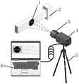
图1是本发明实施例的测量系统示意图。FIG. 1 is a schematic diagram of a measurement system according to an embodiment of the present invention.
图2是本发明实施例中圆形条纹图案示意图。FIG. 2 is a schematic diagram of a circular stripe pattern in an embodiment of the present invention.
图3是本发明实施例的测量方法的处理流程图。FIG. 3 is a process flow chart of the measurement method according to the embodiment of the present invention.
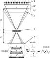
图4是本发明实施例中单密度正弦条纹的测量示意图。FIG. 4 is a schematic diagram of measurement of single-density sinusoidal fringes in an embodiment of the present invention.
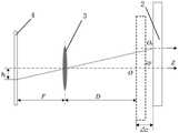
图5是本发明实施例中X方向和Y方向的位移信息测量示意图。FIG. 5 is a schematic diagram of displacement information measurement in the X direction and the Y direction in the embodiment of the present invention.
具体实施方式Detailed ways
下面结合附图及具体实施例对本发明作进一步的详细说明。The present invention will be further described in detail below with reference to the accompanying drawings and specific embodiments.
图1是本发明实施例的测量系统示意图。如图1所示,本发明提供了一种基于单目视觉的结构三维振动测量系统,包括待测结构2、单目视觉传感器4、光学镜头3、可调支架5和具有图像处理模块的计算机6。所述待测结构2表面附有设计好的圆形条纹图案1,所述单目视觉传感器4安装于可调支架5上,所述光学镜头3安装于单目视觉传感器4前端,以通过调节光学镜头得到结构表面清晰的圆形条纹图像。所述单目视觉传感器4通过数据连接线与计算机6连接。结构受到激励产生振动时,结构表面的圆形条纹图案也会随之发生振动。单目视觉传感器4实时采集振动时的圆形条纹图像,并上传采集到的图像信息,计算机6通过图像处理模块对采集到的图像信息进行处理分析,进而计算得到待测结构的三维振动信息。FIG. 1 is a schematic diagram of a measurement system according to an embodiment of the present invention. As shown in FIG. 1 , the present invention provides a structure three-dimensional vibration measurement system based on monocular vision, including a structure to be measured 2, a
图2为本实施例中圆形条纹图案的示意图。在本实施例中,圆形条纹图案主要由两部分组成,包括外围的圆形图案和中心的正弦条纹图案。整个图案打印在纸张上得到具有圆形条纹图案的图片,再将图片贴附于待测结构表面,或者整个图案不打印在纸张上而直接喷涂在待测结构表面。所述圆形条纹图案是在半径为r的黑色圆形图案中心添加密度为f的单密度正弦条纹,且正弦条纹的中心与黑色圆形图案的圆心重合,整个图案上下左右都对称,正弦条纹在长度方向的强度分布为:FIG. 2 is a schematic diagram of a circular stripe pattern in this embodiment. In this embodiment, the circular stripe pattern is mainly composed of two parts, including a peripheral circular pattern and a central sinusoidal stripe pattern. The whole pattern is printed on the paper to obtain a picture with a circular stripe pattern, and then the picture is attached to the surface of the structure to be tested, or the entire pattern is not printed on the paper but directly sprayed on the surface of the structure to be tested. The circular stripe pattern is a single-density sinusoidal stripe with a density of f added to the center of a black circular pattern with a radius of r, and the center of the sinusoidal stripe coincides with the center of the black circular pattern. The entire pattern is symmetrical up and down, left and right, and the sinusoidal stripes The intensity distribution in the length direction is:

其中x是正弦条纹的水平像素点,B是环境背景系数,
本发明还提供了基于上述测量系统的结构三维振动测量方法,包括以下步骤:The present invention also provides a three-dimensional vibration measurement method based on the above-mentioned measurement system, comprising the following steps:
步骤S1:根据待测结构的尺寸设计圆形条纹图案的大小,将圆形条纹图案贴附或喷涂在待测结构表面。Step S1: Design the size of the circular stripe pattern according to the size of the structure to be tested, and attach or spray the circular stripe pattern on the surface of the structure to be tested.
步骤S2:将单目视觉传感器安装于可调支架上,调整好条纹成像位置,并调整光学镜头,使圆形条纹图案清晰地呈现在单目视觉传感器的中心。Step S2: Install the monocular vision sensor on the adjustable bracket, adjust the stripe imaging position, and adjust the optical lens, so that the circular stripe pattern is clearly presented in the center of the monocular vision sensor.
步骤S3:待测结构发生振动时,单目视觉传感器实时采集待测结构振动时的圆形条纹图像,并上传到计算机。Step S3: When the structure to be tested vibrates, the monocular vision sensor collects the circular fringe image when the structure to be tested vibrates in real time, and uploads it to the computer.
步骤S4:计算机通过图像处理模块对采集到的圆形条纹图像进行处理分析,通过能量重心法及能量重心频谱校正法,计算得到待测结构XYZ三个方向的振动信息。Step S4: The computer processes and analyzes the collected circular fringe images through the image processing module, and calculates the vibration information of the structure to be measured in three directions, XYZ, through the energy center of gravity method and the energy center of gravity spectrum correction method.
图3是本发明实施例的测量方法的处理流程图。如图3所示,首先输入视觉传感器拍摄到的圆形条纹图像,分为X方向(Y方向)和Z方向两个过程进行处理。X方向(Y方向)振动信息的获取方法,即X方向(Y方向)的处理步骤为:FIG. 3 is a process flow chart of the measurement method according to the embodiment of the present invention. As shown in Figure 3, the circular stripe image captured by the vision sensor is first input, and processed in two processes: the X direction (Y direction) and the Z direction. The acquisition method of the vibration information in the X direction (Y direction), that is, the processing steps in the X direction (Y direction) are:
步骤A1:读取每帧圆形条纹图像,记为圆形条纹图像A;为了减少噪声对圆形条纹图像能量重心的影响,对圆形条纹图像计算阈值,进行二值处理(大于阈值为1,其余为0),得到二值的圆形条纹图像B。Step A1: Read each frame of the circular fringe image, denoted as circular fringe image A; in order to reduce the influence of noise on the energy center of the circular fringe image, calculate a threshold for the circular fringe image, and perform binary processing (the value greater than the threshold is 1). , and the rest are 0) to obtain a binary circular fringe image B.
步骤A2:为了减少正弦条纹对圆形条纹图像能量重心的影响,对圆形条纹图像B进行连通区域的标定,令圆形条纹图像内部的连通区域的数值都等于0,成为一个标准的圆形图像,得到圆形条纹图像C。Step A2: In order to reduce the influence of the sine fringes on the energy center of the circular fringe image, the connected area of the circular fringe image B is calibrated, so that the values of the connected areas inside the circular fringe image are all equal to 0, which becomes a standard circle. image to obtain the circular fringe image C.
步骤A3:采用能量重心法计算圆形条纹图像C的能量重心坐标(x,y),所述圆形条纹图像的能量重心即是圆形条纹图案的圆心。Step A3: Calculate the energy barycentric coordinates (x, y) of the circular fringe image C by using the energy barycenter method, where the energy barycenter of the circular fringe image is the center of the circular fringe pattern.
能量重心法是对图像计算重心,并输出重心的X坐标和Y坐标,其计算方法如下所示:The energy center of gravity method calculates the center of gravity of the image, and outputs the X and Y coordinates of the center of gravity. The calculation method is as follows:
Ex=Pxi/iEx =Pxi /i
Ey=Pyi/iEy =Pyi /i
其中Ex、Ey分别表示能量重心法计算得到的圆形条纹图像重心的X坐标和Y坐标,i表示图像中数值为0的像素点个数,Pxi和Pyi分别表示数值为0的像素点的X坐标和Y坐标的坐标数值总和。where Ex and Ey represent the X-coordinate and Y-coordinate of the barycenter of the circular fringe image calculated by the energy center of gravity method, respectively, i represents the number of pixels with a value of 0 in the image, and Pxi and Pyi represent the number of pixels with a value of 0, respectively. The sum of the coordinate values of the X coordinate and the Y coordinate of the pixel point.
步骤A4:对每帧圆形条纹图像进行相同的处理,得到每帧圆形条纹图像的能量重心坐标(x’,y’),通过重心坐标的位置变化以及成像关系的换算,计算得到每帧圆形条纹图像X方向和Y方向的振动信息。Step A4: Perform the same processing on each frame of the circular fringe image to obtain the energy barycentric coordinates (x', y') of each frame of the circular fringe image, and obtain each frame by calculating the position change of the barycentric coordinates and the conversion of the imaging relationship. Vibration information in the X and Y directions of the circular fringe image.
Z方向振动信息的获取方法,即Z方向的处理步骤为:The acquisition method of the vibration information in the Z direction, that is, the processing steps in the Z direction are:
步骤B1:直接读取图像且不做任何预处理,保留条纹图像最原始的信息;通过步骤A3得到每帧圆形条纹图像的能量重心坐标(x’,y’),可以精确地定位到正弦条纹所在的行和列,以(x’,y’)为中心提取单密度正弦条纹所在的单行像素点。Step B1: Read the image directly without any preprocessing, and retain the most original information of the fringe image; obtain the energy barycentric coordinates (x', y') of each frame of the circular fringe image through Step A3, which can be accurately positioned to the sine The row and column where the stripes are located, and the single-row pixel points where the single-density sinusoidal stripes are located are extracted with (x', y') as the center.
步骤B2:采用能量重心频谱校正法对步骤B1中的正弦条纹进行处理,得到条纹密度d。Step B2: The sinusoidal fringes in step B1 are processed by using the energy center of gravity spectrum correction method to obtain the fringe density d.
步骤B3:对每帧圆形条纹图像进行相同的处理,得到各帧正弦条纹的密度d(t),然后将结构静止时的正弦条纹密度作为参考密度d0;通过条纹的密度变化以及成像关系的换算,计算得到每帧圆形条纹图像Z方向的振动信息Δz(t)。Step B3: Perform the same processing on each frame of the circular fringe image to obtain the density d(t) of the sinusoidal fringes in each frame, and then use the sinusoidal fringe density when the structure is stationary as the reference density d0 ; through the density change of the fringes and the imaging relationship , the vibration information Δz(t) in the Z direction of each frame of circular fringe image is obtained by calculation.
图4为本实施例中单密度正弦条纹的测量示意图。在本实施例中,圆形条纹图案1贴附或喷涂在待测结构2的表面。通过调节光学镜头3使条纹图案1在单目视觉传感器4上得到清晰的条纹图像。当待测结构发生振动时,其与光学镜头3物距D会发生变化,进而导致视觉传感器4得到的条纹图像发生变化。对所有每帧的正弦条纹进行傅里叶变换(FFT)且运用能量重心频谱校正法(SCCM)可得到精确的条纹密度d(t),并将结构静止时的条纹密度d0作为参考帧,通过条纹密度之间的变化来反映待测结构的Z方向的振动信息。待测结构Z方向的时域位移振动信号Δz(t)的计算方法为:FIG. 4 is a schematic diagram of the measurement of single-density sinusoidal fringes in this embodiment. In this embodiment, the

其中Δz(t)为待测结构在t时刻的Z方向位移,D为成像系统的初始物距,d0为参考帧条纹图像中的正弦条纹密度,d(t)为t时刻条纹图像中的正弦条纹密度。where Δz(t) is the Z-direction displacement of the structure to be tested at time t, D is the initial object distance of the imaging system, d0 is the sinusoidal fringe density in the fringe image of the reference frame, and d(t) is the fringe image in the fringe image at time t Sinusoidal fringe density.
初始物距D可以通过光学成像原理求得,其计算公式为:The initial object distance D can be obtained through the principle of optical imaging, and its calculation formula is:

其中f为光学镜头组的焦距,A为待测结构表面的单密度正弦条纹实际长度,p为单目视觉传感器的像素点物理尺寸,n为参考帧图像中正弦条纹所占的像素点个数。where f is the focal length of the optical lens group, A is the actual length of the single-density sinusoidal fringes on the surface of the structure to be measured, p is the pixel physical size of the monocular vision sensor, and n is the number of pixels occupied by the sinusoidal fringes in the reference frame image .
图5为本实施例中Y方向(X方向)重心位置变化及光学换算关系图。因为X方向和Y方向上的位移求解步骤都是相同的,故只以Y方向为例加以说明。待测结构2上的条纹图案在Y方向发生了Δy的偏移量,经过相机的成像原理,在视觉传感器上采集到的条纹图案也会产生hy的偏移量,圆形条纹图像的偏移量、像素点大小以及像素点个数的关系可表示为:FIG. 5 is a graph of the change in the position of the center of gravity in the Y direction (X direction) and an optical conversion relationship in this embodiment. Because the displacement solving steps in the X direction and the Y direction are the same, only the Y direction is used as an example for description. The fringe pattern on the structure to be tested 2 has an offset of Δy in the Y direction. Through the imaging principle of the camera, the fringe pattern collected on the vision sensor will also have an offset of hy , and the offset of the circular fringe image. The relationship between shift amount, pixel size and number of pixels can be expressed as:
hy=p×mhy =p×m
其中hy是待测结构在图像上Y方向的位移,p为传感器像素点大小,m为hy所占的像素点个数。Where hy is the displacement of the structure to be tested in theY direction on the image, p is the size of the sensor pixel, and m is the number of pixels occupied byhy .
Y方向在有Z方向位移影响下的位置变化与光学成像原理的简图如图5所示。其所对应的光学成像关系为:Figure 5 shows a schematic diagram of the position change in the Y direction under the influence of the Z direction displacement and the principle of optical imaging. The corresponding optical imaging relationship is:


其中A为图4中待测结构表面的正弦条纹实际长度,n为参考帧图像中正弦条纹所占的像素点个数,令P=A/n,P为成像分辨率,即每个像素点对应的实际物体长度。where A is the actual length of the sinusoidal fringes on the surface of the structure to be tested in Figure 4, n is the number of pixels occupied by the sinusoidal fringes in the reference frame image, let P=A/n, and P is the imaging resolution, that is, each pixel The corresponding actual object length.
最后,Y方向振动信息可表示为:Finally, the Y-direction vibration information can be expressed as:

所述的X方向和Y方向振动信息处理步骤相同,故X方向的位置变化以及光学成像原理的具体关系也可表示为:The vibration information processing steps in the X direction and the Y direction are the same, so the position change in the X direction and the specific relationship of the optical imaging principle can also be expressed as:

其中Δx(t)、Δy(t)分别为待测结构在t时刻的X方向、Y方向位移,mx、my分别为t时刻图像重心与参考帧图像重心在X方向、Y方向偏移的像素点个数,d(t)为t时刻条纹图像中的正弦条纹密度,d0为参考帧条纹图像中的正弦条纹密度。where Δx(t) and Δy(t) are the displacements of the structure to be tested in the X and Y directions at time t, respectively, and mx and my are the shifts between the center of gravity of the image at time t and the center of gravity of the reference frame image in the X and Y directions, respectively. , d(t) is the sinusoidal fringe density in the fringe image at time t, and d0 is the sinusoidal fringe density in the fringe image of the reference frame.
以上是本发明的较佳实施例,凡依本发明技术方案所作的改变,所产生的功能作用未超出本发明技术方案的范围时,均属于本发明的保护范围。The above are the preferred embodiments of the present invention, all changes made according to the technical solutions of the present invention, when the resulting functional effects do not exceed the scope of the technical solutions of the present invention, belong to the protection scope of the present invention.
Claims (3)
Translated fromChinese


Priority Applications (1)
| Application Number | Priority Date | Filing Date | Title |
|---|---|---|---|
| CN202011634525.2ACN112683382B (en) | 2020-12-31 | 2020-12-31 | Structure three-dimensional vibration measurement system and method based on monocular vision |
Applications Claiming Priority (1)
| Application Number | Priority Date | Filing Date | Title |
|---|---|---|---|
| CN202011634525.2ACN112683382B (en) | 2020-12-31 | 2020-12-31 | Structure three-dimensional vibration measurement system and method based on monocular vision |
Publications (2)
| Publication Number | Publication Date |
|---|---|
| CN112683382A CN112683382A (en) | 2021-04-20 |
| CN112683382Btrue CN112683382B (en) | 2022-05-13 |
Family
ID=75456317
Family Applications (1)
| Application Number | Title | Priority Date | Filing Date |
|---|---|---|---|
| CN202011634525.2AActiveCN112683382B (en) | 2020-12-31 | 2020-12-31 | Structure three-dimensional vibration measurement system and method based on monocular vision |
Country Status (1)
| Country | Link |
|---|---|
| CN (1) | CN112683382B (en) |
Families Citing this family (3)
| Publication number | Priority date | Publication date | Assignee | Title |
|---|---|---|---|---|
| CN113340403B (en)* | 2021-05-31 | 2022-08-16 | 福州大学 | Rotating shaft radial vibration measuring method based on circumferential stripes and linear array camera |
| CN114485424B (en)* | 2022-02-09 | 2023-04-28 | 福州大学 | Apparatus and method for visual measurement of radial vibration displacement of rotating shaft based on projected fringes |
| CN114543972B (en)* | 2022-02-25 | 2023-04-11 | 福州大学 | Rotating shaft three-dimensional vibration displacement measuring device and method based on area-array camera |
Citations (4)
| Publication number | Priority date | Publication date | Assignee | Title |
|---|---|---|---|---|
| CN104614064A (en)* | 2015-02-13 | 2015-05-13 | 福州大学 | High speed multi-dimensional vibration measuring device and method based on stripe target |
| CN206974541U (en)* | 2017-06-20 | 2018-02-06 | 福州大学 | A kind of device of rotating shaft three-dimensional vibrating synchro measure |
| CN109357621A (en)* | 2018-12-10 | 2019-02-19 | 福州大学 | Three-dimensional vibration displacement measurement device and method based on line scan camera and position-sensing fringes |
| CN109374117A (en)* | 2018-12-21 | 2019-02-22 | 福州大学 | Sound measuring device and method based on sound-sensing striped film |
- 2020
- 2020-12-31CNCN202011634525.2Apatent/CN112683382B/enactiveActive
Patent Citations (4)
| Publication number | Priority date | Publication date | Assignee | Title |
|---|---|---|---|---|
| CN104614064A (en)* | 2015-02-13 | 2015-05-13 | 福州大学 | High speed multi-dimensional vibration measuring device and method based on stripe target |
| CN206974541U (en)* | 2017-06-20 | 2018-02-06 | 福州大学 | A kind of device of rotating shaft three-dimensional vibrating synchro measure |
| CN109357621A (en)* | 2018-12-10 | 2019-02-19 | 福州大学 | Three-dimensional vibration displacement measurement device and method based on line scan camera and position-sensing fringes |
| CN109374117A (en)* | 2018-12-21 | 2019-02-22 | 福州大学 | Sound measuring device and method based on sound-sensing striped film |
Non-Patent Citations (1)
| Title |
|---|
| 位感条纹三维振动测量原理及试验研究;钟剑锋 等;《机械工程学报》;20190731;第55卷(第14期);第19-29页* |
Also Published As
| Publication number | Publication date |
|---|---|
| CN112683382A (en) | 2021-04-20 |
Similar Documents
| Publication | Publication Date | Title |
|---|---|---|
| CN112683382B (en) | Structure three-dimensional vibration measurement system and method based on monocular vision | |
| CN104864819B (en) | A high-speed three-dimensional strain measurement method based on digital speckle | |
| CN102498368B (en) | The device of remote displacement sensor and system thereof including optical strain gauge | |
| CN102183214B (en) | Light detection method for large-aperture aspherical mirror structure | |
| CN102207371B (en) | Three-dimensional point coordinate measuring method and measuring apparatus thereof | |
| CN109357621B (en) | Three-dimensional vibration displacement measurement device and method based on line scan camera and position-sensing fringes | |
| CN107817044B (en) | Device and method for measuring plate vibration based on machine vision | |
| Molleda et al. | An improved 3D imaging system for dimensional quality inspection of rolled products in the metal industry | |
| CN111829448A (en) | An optical extensometer and uniform strain measurement method based on lens imaging and double prism reflection | |
| CN107271025A (en) | A kind of device and method of rotating shaft three-dimensional vibrating synchro measure | |
| CN113324483B (en) | A measuring device and measuring method for medium-thick plate size | |
| CN101561251A (en) | Phase target-based optical three-coordinate measuring method | |
| CN110806182A (en) | High-precision optical extensometer and measurement method based on telecentric lens | |
| CN102062574B (en) | Method and device for measuring three-dimensional coordinate of object | |
| CN113340403B (en) | Rotating shaft radial vibration measuring method based on circumferential stripes and linear array camera | |
| CN110057312A (en) | A kind of monocular vision three-dimensional scanning measurement device and measurement method based on structure light | |
| CN113175894A (en) | Object surface three-dimensional shape white light interferometry device and method | |
| Hartlieb et al. | Multi-positional image-based vibration measurement by holographic image replication | |
| CN104713478B (en) | A kind of linear motor rotor location measurement method | |
| CN108534704A (en) | Cylinder inner wall detection system based on structured light | |
| Xu et al. | Reconstruction method adopting laser plane generated from RANSAC and three dimensional reference | |
| CN105891842A (en) | Height and distance measuring apparatus based on camera and laser emitter | |
| Jin et al. | The measurement method for the size of the hole on the part surface based on grating image processing | |
| CN108489422A (en) | A kind of method of frequency conversion phase shift least-squares iteration superposition face shape separation | |
| CN218035604U (en) | Tail support mode wind tunnel test elastic deformation measuring device |
Legal Events
| Date | Code | Title | Description |
|---|---|---|---|
| PB01 | Publication | ||
| PB01 | Publication | ||
| SE01 | Entry into force of request for substantive examination | ||
| SE01 | Entry into force of request for substantive examination | ||
| GR01 | Patent grant | ||
| GR01 | Patent grant |