CN112680338B - Inoculation and sampling device for walnut endophytic bacterium HB1310 fermented cotton stalk hydrolyzed sugar liquid oil production fermentation broth - Google Patents
Inoculation and sampling device for walnut endophytic bacterium HB1310 fermented cotton stalk hydrolyzed sugar liquid oil production fermentation brothDownload PDFInfo
- Publication number
- CN112680338B CN112680338BCN202110095401.XACN202110095401ACN112680338BCN 112680338 BCN112680338 BCN 112680338BCN 202110095401 ACN202110095401 ACN 202110095401ACN 112680338 BCN112680338 BCN 112680338B
- Authority
- CN
- China
- Prior art keywords
- plate
- block
- hole
- inoculation
- ring
- Prior art date
- Legal status (The legal status is an assumption and is not a legal conclusion. Google has not performed a legal analysis and makes no representation as to the accuracy of the status listed.)
- Active
Links
Images


Classifications
- Y—GENERAL TAGGING OF NEW TECHNOLOGICAL DEVELOPMENTS; GENERAL TAGGING OF CROSS-SECTIONAL TECHNOLOGIES SPANNING OVER SEVERAL SECTIONS OF THE IPC; TECHNICAL SUBJECTS COVERED BY FORMER USPC CROSS-REFERENCE ART COLLECTIONS [XRACs] AND DIGESTS
- Y02—TECHNOLOGIES OR APPLICATIONS FOR MITIGATION OR ADAPTATION AGAINST CLIMATE CHANGE
- Y02E—REDUCTION OF GREENHOUSE GAS [GHG] EMISSIONS, RELATED TO ENERGY GENERATION, TRANSMISSION OR DISTRIBUTION
- Y02E50/00—Technologies for the production of fuel of non-fossil origin
- Y02E50/10—Biofuels, e.g. bio-diesel
Landscapes
- Apparatus Associated With Microorganisms And Enzymes (AREA)
Abstract
Description
Translated fromChinese技术领域technical field
本发明涉及接种及采样装置技术领域。具体地说是核桃内生细菌HB1310发酵棉杆水解糖液产油发酵液接种及采样装置。The invention relates to the technical field of inoculation and sampling devices. Specifically, it is an inoculation and sampling device for fermenting walnut endophytic bacteria HB1310 to ferment cotton stalk hydrolysis sugar liquid to produce oil.
背景技术Background technique
核桃内生细菌HB1310是一种好氧细菌,在对其进行接种时,需要用到专门的接种装置,而现有技术中常用的接种方式有液体稀释法和固体平板扩散法,液体稀释法的接种采用斜面接种法,目前的自动接种设备基本采用平板划线法,无法采用斜面接种法进行接种,使得液体稀释法需要人工手动完成,效率较低,且操作过程较为复杂,而在对其进行接种前需要对其进行采样,如果先采样再接种,步骤繁琐且复杂,本发明提出一种解决上述问题的装置。Walnut endophytic bacteria HB1310 is an aerobic bacterium. When inoculating it, a special inoculation device is required. The commonly used inoculation methods in the prior art include liquid dilution method and solid plate diffusion method. The inoculation adopts the inclined plane inoculation method. The current automatic inoculation equipment basically adopts the plate scribing method, and the inclined plane inoculation method cannot be used for inoculation, so that the liquid dilution method needs to be completed manually, which is inefficient and the operation process is relatively complicated. It needs to be sampled before inoculation. If sampling first and then inoculation, the steps are cumbersome and complicated. The present invention proposes a device to solve the above problems.
发明内容Contents of the invention
为此,本发明所要解决的技术问题在于提供一种将接种装置及采样装置一体化的核桃内生细菌HB1310发酵棉杆水解糖液产油发酵液接种及采样装置。For this reason, the technical problem to be solved by the present invention is to provide an inoculation and sampling device for fermenting cotton stalk hydrolyzed sugar liquid oil production fermentation liquid by walnut endophytic bacteria HB1310 which integrates an inoculation device and a sampling device.
为解决上述技术问题,本发明提供如下技术方案:核桃内生细菌HB1310发酵棉杆水解糖液产油发酵液接种及采样装置,包括接种机构、处理机构、目标机构、密封机构和采样机构;In order to solve the above-mentioned technical problems, the present invention provides the following technical solutions: an inoculation and sampling device for fermenting cotton stalk hydrolysis sugar liquid oil production fermentation liquid by walnut endophytic bacteria HB1310, including an inoculation mechanism, a processing mechanism, a target mechanism, a sealing mechanism and a sampling mechanism;
所述接种机构固定安装在本装置的最右侧,所述处理机构固定安装在目标机构的正上方,所述密封机构设置在目标机构的右侧,所述采样机构设置在目标机构的上方,且位于处理机构的下方。The inoculation mechanism is fixedly installed on the far right side of the device, the processing mechanism is fixedly installed directly above the target mechanism, the sealing mechanism is arranged on the right side of the target mechanism, and the sampling mechanism is arranged above the target mechanism. And located below the processing mechanism.
上述核桃内生细菌HB1310发酵棉杆水解糖液产油发酵液接种及采样装置,所述接种机构包括底座、第一支撑板、第一滑槽、第一滑块、第二支撑板、第二滑槽、第二滑块、第一支撑杆、气压缸、放气阀、第一弹簧、气压板、连接杆、安装箱、第二弹簧、移动孔、限位环、第一微型弹簧、控制杆、连接块、接种环、受力杆、第一挤压板、往复电机、第二挤压板、第二微型弹簧、进气孔、供气缸、隔板、供气腔、第三弹簧、封块、限位块、推杆、第三挤压板、出气孔、进气管、气泵;The above-mentioned inoculation and sampling device for fermented cotton stalk hydrolysis sugar liquid oil production fermentation liquid by HB1310 fermented walnut endophytic bacteria, the inoculation mechanism includes a base, a first support plate, a first chute, a first slider, a second support plate, a second Chute, second slider, first support rod, pneumatic cylinder, air release valve, first spring, air pressure plate, connecting rod, installation box, second spring, moving hole, limit ring, first miniature spring, control Rod, connection block, inoculation ring, force rod, first extrusion plate, reciprocating motor, second extrusion plate, second miniature spring, air intake hole, air supply cylinder, partition plate, air supply chamber, third spring, Sealing block, limit block, push rod, third extrusion plate, air outlet, air intake pipe, air pump;
所述第一支撑板固定安装在底座上表面的最右侧,所述第一支撑板的左侧面开设有第一滑槽,所述第一滑槽的内部滑动安装有第一滑块;所述第一滑块的左侧靠近底端的位置固定安装有第二支撑板,第二支撑板的上表面开设有第二滑槽,所述第二滑槽的内部滑动安装有第二滑块,所述第二滑块的上表面固定安装有第一支撑杆,且所述第一支撑杆的形状为L形;The first support plate is fixedly installed on the far right side of the upper surface of the base, the left side of the first support plate is provided with a first chute, and a first slider is slidably installed inside the first chute; A second support plate is fixedly installed on the left side of the first slider close to the bottom end, and a second chute is opened on the upper surface of the second support plate, and a second slider is slidably installed inside the second chute , the upper surface of the second slider is fixedly installed with a first support rod, and the shape of the first support rod is L-shaped;
所述第一支撑杆远离第一支撑板的一端下表面固定安装有气压缸,所述气压缸的左侧靠近顶端的位置设置有放气阀,所述放气阀由控制器控制;所述气压缸内部的上表面固定安装有第一弹簧,所述第一弹簧的底端固定安装有气压板,所述气压板的直径与气压缸的直径大小相等,所述气压板的下表面中心处固定安装有连接杆,所述连接杆的底端贯穿气压缸的下表面凸出气压缸设置;A pneumatic cylinder is fixedly installed on the lower surface of one end of the first support rod far away from the first support plate, and an air release valve is arranged on the left side of the air cylinder close to the top, and the air release valve is controlled by a controller; The upper surface inside the pneumatic cylinder is fixedly equipped with a first spring, the bottom end of the first spring is fixedly equipped with an air pressure plate, the diameter of the air pressure plate is equal to the diameter of the air pressure cylinder, and the center of the lower surface of the air pressure plate A connecting rod is fixedly installed, and the bottom end of the connecting rod penetrates the lower surface of the pneumatic cylinder and protrudes from the pneumatic cylinder;
所述连接杆的底端固定安装有安装箱,所述第一弹簧的拉力大于安装箱和安装箱内部零件的总重量;所述安装箱内部的上表面固定安装有第二弹簧,所述安装箱的两侧均贯穿开设有移动孔,两个所述移动孔位于同一条轴线上,所述移动孔的内部设置有限位环,所述限位环贯穿两个移动孔,且限位环上固定有限制件防止限位环通过两端的移动孔掉出;The bottom end of the connecting rod is fixedly installed with an installation box, and the tension of the first spring is greater than the total weight of the installation box and the internal parts of the installation box; the upper surface inside the installation box is fixedly installed with a second spring, and the installation Both sides of the box are provided with moving holes, the two moving holes are located on the same axis, and a limit ring is arranged inside the moving hole, and the limit ring runs through the two moving holes, and the limit ring A limit piece is fixed to prevent the limit ring from falling out through the moving holes at both ends;
所述限位环的内部固定安装有多个第一微型弹簧,所述第一微型弹簧的另一端固定安装有控制杆,所述控制杆的两端均凸出限位环,所述控制杆的左端固定安装有连接块,所述连接块的另一侧固定安装有接种环;A plurality of first miniature springs are fixedly installed inside the limiting ring, and a control rod is fixedly installed on the other end of the first miniature spring, and both ends of the control rod protrude from the limiting ring, and the control rod A connecting block is fixedly installed on the left end of the connecting block, and an inoculation loop is fixedly installed on the other side of the connecting block;
所述控制杆位于安装箱内的一侧固定安装有受力杆,所述受力杆的另一端贯穿控制杆固定安装有第一挤压板;所述安装箱的外表面与第一挤压板相对应的一侧固定安装有往复电机,所述往复电机的输出端贯穿安装箱固定安装有第二挤压板,所述第二挤压板与第一挤压板位于同一条轴线上,所述第二挤压板与第一挤压板相照应的一侧固定安装有第二微型弹簧,所述第二微型弹簧的数量为多个;One side of the control rod located in the installation box is fixedly installed with a force rod, and the other end of the force rod penetrates through the control rod and is fixedly installed with a first extrusion plate; the outer surface of the installation box and the first extrusion A reciprocating motor is fixedly installed on the corresponding side of the plate, and the output end of the reciprocating motor passes through the installation box and is fixedly installed with a second extruding plate, the second extruding plate is located on the same axis as the first extruding plate, A second miniature spring is fixedly installed on the corresponding side of the second compression plate to the first compression plate, and the number of the second miniature springs is multiple;
所述气压缸的右侧靠近顶端的位置开设有进气孔,正常状态下,所述进气孔位于气压板的上方;所述供气缸固定安装在气压缸的右侧,且所述进气孔贯穿供气缸的一侧设置,所述供气缸的内部固定安装有隔板,所述供气缸内部由隔板分割出来有供气腔;The right side of the pneumatic cylinder is provided with an air intake hole near the top. Under normal conditions, the air intake hole is located above the air pressure plate; the air supply cylinder is fixedly installed on the right side of the pneumatic cylinder, and the air intake The hole is set through one side of the air supply cylinder, and the interior of the air supply cylinder is fixedly installed with a partition, and the interior of the air supply cylinder is divided by the partition to form an air supply chamber;
所述供气腔的上表面固定安装有第三弹簧,所述第三弹簧的底端固定安装有封块,所述封块的长等于供气腔的一侧倒隔板一侧的长度;所述供气缸内部的一侧与隔板的一侧均固定安装有限位块,所述供气缸与隔板上的限位块均对称设置,所述供气缸上的限位块均位于进气孔的上方与下方;正常状态下,所述封块位于进气孔下方的封块上,且所述封块的上表面与进气孔的下表面平齐;A third spring is fixedly installed on the upper surface of the air supply chamber, and a block is fixedly installed at the bottom end of the third spring, and the length of the block is equal to the length from one side of the air supply chamber to the side of the partition; One side of the air supply cylinder and one side of the partition are fixed with a limit block, and the limit blocks on the air supply cylinder and the partition are symmetrically arranged, and the limit blocks on the air supply cylinder are all located at the inlet Above and below the hole; under normal conditions, the block is located on the block below the air intake hole, and the upper surface of the block is flush with the lower surface of the air intake hole;
所述封块的底端中心处固定安装有推杆,所述供气缸的底端开设有供推杆通过的通孔,所述推杆的底端固定安装有第三挤压板,正常状态下,所述第三挤压板与移动孔的中心位置平齐;A push rod is fixedly installed at the center of the bottom end of the block, a through hole for the push rod to pass is opened at the bottom end of the air supply cylinder, and a third extruding plate is fixedly installed at the bottom end of the push rod. Next, the third extrusion plate is flush with the center of the moving hole;
所述供气缸的一侧开设有出气孔,所述出气孔与封块的底部连通;所述供气缸的一侧固定安装有进气管,所述进气管与封块上方位置相连通,且所述进气管为软管,所述底座的上表面固定安装有气泵,所述气泵的出气口与进气管相连接。One side of the air supply cylinder is provided with an air outlet, and the air outlet communicates with the bottom of the block; one side of the air supply cylinder is fixedly installed with an air intake pipe, and the air intake pipe communicates with the position above the block, and the The air intake pipe is a flexible pipe, an air pump is fixedly installed on the upper surface of the base, and the air outlet of the air pump is connected with the air intake pipe.
上述核桃内生细菌HB1310发酵棉杆水解糖液产油发酵液接种及采样装置,所述处理机构包括第三支撑板、消毒环、冷却箱、制冷器、冷却环;The above-mentioned walnut endophytic bacteria HB1310 fermentation cotton stalk hydrolysis sugar liquid oil production fermentation liquid inoculation and sampling device, the processing mechanism includes a third support plate, a disinfection ring, a cooling box, a refrigerator, and a cooling ring;
所述第三支撑板固定安装在底座的上表面,且所述第三支撑板位于第一支撑板的左侧;所述第三支撑板与第一支撑板相照应的一侧固定安装有消毒环,所述消毒环与第一支撑板相照应的一端为通孔设置,且所述消毒环的内孔直径大于接种环的直径,且所述消毒环的长度大于接种环的长度;The third support plate is fixedly installed on the upper surface of the base, and the third support plate is located on the left side of the first support plate; the side of the third support plate corresponding to the first support plate is fixedly installed with a disinfection A ring, one end of the disinfection ring corresponding to the first support plate is provided with a through hole, and the diameter of the inner hole of the disinfection ring is greater than the diameter of the inoculation loop, and the length of the disinfection ring is greater than the length of the inoculation loop;
所述冷却箱固定安装在第三支撑板与第一支撑板相照应的一侧,且所述冷却箱位于消毒环的下方,所述冷却箱右端为通孔设置,所述冷却箱内部的左侧固定安装有制冷器,所述制冷器的右端面固定安装有冷却环,所述冷却环为右端开口的环形管,所述冷却环采用高导冷材料制成,且所述冷却环的内直径大于接种环的直径。The cooling box is fixedly installed on the corresponding side of the third support plate and the first support plate, and the cooling box is located below the disinfection ring, the right end of the cooling box is provided with a through hole, and the left side of the inside of the cooling box A refrigerator is fixedly installed on the side of the refrigerator, and a cooling ring is fixedly installed on the right end of the refrigerator. The cooling ring is an annular tube with an opening at the right end. The diameter is larger than the diameter of the inoculating loop.
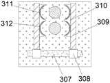
上述核桃内生细菌HB1310发酵棉杆水解糖液产油发酵液接种及采样装置,所述目标机构包括安装块、第一安装孔、第二安装孔、缓震棉、第一试管、第二试管、第三滑槽、第三滑块、第二支撑杆、锁紧块、保护垫、灭菌器;The aforementioned walnut endophytic bacteria HB1310 fermented cotton stalk hydrolysis sugar liquid oil production fermentation liquid inoculation and sampling device, the target mechanism includes a mounting block, a first mounting hole, a second mounting hole, cushioning cotton, a first test tube, and a second test tube , the third chute, the third slider, the second support rod, locking block, protective pad, sterilizer;
所述安装块固定安装在第三支撑板的右侧,所述安装块位于冷却箱的正下方,所述安装块的内部开设有第一安装孔与第二安装孔,所述第二安装孔位于第一安装孔的正下方,且所述第一安装孔与第二安装孔的右端均为通透设置,所述第一安装孔与第二安装孔的内部左端均固定安装有缓震棉,所述第一安装孔与第二安装孔的内部分别设置有第一试管和第二试管,所述第一试管与第二试管的右端凸出安装块设置;The installation block is fixedly installed on the right side of the third support plate, the installation block is located directly below the cooling box, and the inside of the installation block is provided with a first installation hole and a second installation hole, and the second installation hole It is located directly below the first installation hole, and the right ends of the first installation hole and the second installation hole are transparently set, and the inner left ends of the first installation hole and the second installation hole are fixedly installed with cushioning cotton , the inside of the first installation hole and the second installation hole are respectively provided with a first test tube and a second test tube, and the right ends of the first test tube and the second test tube protrude from the installation block;
所述安装块的右侧开设有第三滑槽,所述第三滑槽位于第二试管的正下方,所述第三滑槽为平行于底座设置;所述第三滑槽的内部滑动安装有第三滑块,所述第三滑块的数量为两个,两个第三滑块的上表面均固定安装有第二支撑杆,两个第二支撑杆相照应的一侧均固定安装有锁紧块,所述锁紧块为弧形设置,且所述两个第二支撑杆上的两个锁紧块正好能够对两个试管进行固定;所述锁紧块的弧形部位与两个试管接触部位均固定安装有保护垫,所述保护垫采用弹性物质制成,所述锁紧块的右侧固定安装有灭菌器,所述灭菌器为与锁紧块相吻合的弧形。The right side of the mounting block is provided with a third chute, the third chute is located directly below the second test tube, and the third chute is arranged parallel to the base; the inside of the third chute is slidably installed There is a third slider, the number of the third slider is two, the upper surfaces of the two third sliders are fixedly installed with second support rods, and the corresponding sides of the two second support rods are fixedly installed There is a locking block, the locking block is arranged in an arc shape, and the two locking blocks on the two second support rods can just fix the two test tubes; The contact parts of the two test tubes are fixed with a protective pad, the protective pad is made of elastic material, and the right side of the locking block is fixed with a sterilizer, and the sterilizer is matched with the locking block. arc.
上述核桃内生细菌HB1310发酵棉杆水解糖液产油发酵液接种及采样装置,所述密封机构包括第四支撑板、第四滑槽、第四滑块、第三支撑杆、密封盖;The aforementioned walnut endophytic bacteria HB1310 fermented cotton stalk hydrolysis sugar liquid oil production fermentation liquid inoculation and sampling device, the sealing mechanism includes a fourth support plate, a fourth chute, a fourth slider, a third support rod, and a sealing cover;
所述第四支撑板固定安装在底座的上表面,所述第四支撑板位于安装块的右侧,所述第四支撑板的上表面开设有第四滑槽,所述第四滑槽为L形,所述第四滑槽垂直与安装块的一端与两个试管位于同一平面上,所述第四滑槽的内部滑动安装有第四滑块,所述第四滑块的上表面固定安装有第三支撑杆,所述第三支撑杆垂直于安装块贯穿固定安装有密封盖,所述密封盖的数量为两个,所护密封盖的直径与两个试管相吻合。The fourth supporting plate is fixedly installed on the upper surface of the base, the fourth supporting plate is located on the right side of the mounting block, and the upper surface of the fourth supporting plate is provided with a fourth chute, and the fourth chute is L-shaped, the fourth chute is perpendicular to one end of the mounting block and the two test tubes are on the same plane, the inside of the fourth chute is slidably installed with a fourth slider, and the upper surface of the fourth slider is fixed A third support rod is installed, and the third support rod is perpendicular to the installation block and is fixedly installed with a sealing cover. The number of the sealing covers is two, and the diameter of the sealing cover to be protected coincides with the two test tubes.
上述核桃内生细菌HB1310发酵棉杆水解糖液产油发酵液接种及采样装置,所述采样机构包括第五支撑板、第五滑槽、第五滑块、第六支撑板、第六滑槽、第六滑块、导液管、第七支撑板、储液箱、软管、控制阀、第七滑槽、第七滑块、第四支撑杆、第五支撑杆、限位孔;The aforementioned walnut endophytic bacteria HB1310 fermented cotton stalk hydrolysis sugar liquid oil production fermentation liquid inoculation and sampling device, the sampling mechanism includes the fifth support plate, the fifth chute, the fifth slider, the sixth support plate, the sixth chute , the sixth slider, the catheter, the seventh support plate, the liquid storage tank, the hose, the control valve, the seventh chute, the seventh slider, the fourth support rod, the fifth support rod, and the limit hole;
所述第五支撑板固定安装在底座的上表面,所述第五支撑板位于第三支撑板的左侧,所述第五支撑板的上表面开设有第五滑槽,所述第五滑槽的内部滑动安装有第五滑块,所述第五滑块的上表面固定安装有第六支撑板,所述第六支撑板的右侧开设有第六滑槽,所述第六滑槽内部滑动安装有第六滑块,所述第六滑块的右侧表面固定安装有导液管;The fifth support plate is fixedly installed on the upper surface of the base, the fifth support plate is located on the left side of the third support plate, the upper surface of the fifth support plate is provided with a fifth chute, and the fifth slide The inside of the groove is slidably installed with a fifth slider, the upper surface of the fifth slider is fixedly installed with a sixth support plate, and the right side of the sixth support plate is provided with a sixth chute, and the sixth chute A sixth slider is slidably installed inside, and a catheter is fixedly installed on the right side surface of the sixth slider;
所述第三支撑板的左侧面靠近顶端的位置固定安装有第七支撑板,所述第七支撑板的上表面固定安装有储液箱,所述储液箱的出液口与软管固定连接,所述软管贯穿第七支撑板的底端与导液管的右端相连接,所述储液箱位于导液管的上方,所述软管上设置有控制阀,所述控制阀由控制器控制;A seventh support plate is fixedly installed on the left side of the third support plate near the top, a liquid storage tank is fixedly installed on the upper surface of the seventh support plate, and the liquid outlet of the liquid storage tank is connected to the hose. Fixedly connected, the flexible pipe runs through the bottom end of the seventh support plate and is connected with the right end of the catheter, the liquid storage tank is located above the catheter, and a control valve is arranged on the flexible pipe, and the control valve controlled by the controller;
所述第三支撑板的右侧固定开设有第七滑槽,所述第七滑槽位于安装块的上方,且所述第七滑槽位于冷却箱的下方;所述第七滑块的右侧面固定安装有第四支撑杆,所述第四支撑杆的底部固定安装有第五支撑杆,所述第五支撑杆的形状为L形,所述第五支撑杆远离第四支撑杆的一端开设有限位孔,所述限位孔与两个试管位于同一平面上。The right side of the third support plate is fixed with a seventh chute, the seventh chute is located above the mounting block, and the seventh chute is located below the cooling box; the right side of the seventh slide block A fourth support rod is fixedly installed on the side, and a fifth support rod is fixedly installed on the bottom of the fourth support rod. The shape of the fifth support rod is L-shaped, and the fifth support rod is far away from the bottom of the fourth support rod. A limiting hole is provided at one end, and the limiting hole is located on the same plane as the two test tubes.
本发明的技术方案取得了如下有益的技术效果:The technical solution of the present invention has achieved the following beneficial technical effects:
1、本发明,通过设置接种机构与采样机构,实现了细菌接种和采样一体化的目的,操作简单;在开始接种前,在储液箱内加入发酵液,然后使第五滑块向右运行,当下方导液管超过第一试管的最右端时,使第七滑块向下运行,当导液管下方与第一试管平齐时,第七滑块停止运行,然后第五滑块向左运行,进而带动导液管的下方管道插入第一试管内,停止后,控制阀开启,使储液箱内的发酵液流入第一试管内,然后用相反的步骤使导液管返回原来的位置;然后第一滑块带动第二支撑板上下运动,使接种环对准消毒环,然后第二滑块带动第一支撑杆向左运行,使接种环插入消毒环内,进行消毒后,第二滑块带动第一支撑杆向右运行,使接种环退出消毒环,然后第一滑块向下运行,用同样的步骤,使接种环插入冷却环内,接种环冷却后,用以上方法使接种环进入第一试管内,然后气泵向气压缸内通气,通过气体压力推动气压板下降,进而使接种环沾上发酵液,然后使接种环退出第一试管,然后使接种环进入第二试管,然后往复电机运行,推动接种环左右进行震动的同时,使接种环渐渐的退出第二试管,通过震动,接种环上的发酵液会均匀的落到第二试管里的培养基上。1. In the present invention, by setting the inoculation mechanism and the sampling mechanism, the purpose of integrating bacterial inoculation and sampling is realized, and the operation is simple; before inoculation, add fermentation liquid in the liquid storage tank, and then make the fifth slider run to the right , when the lower catheter exceeds the rightmost end of the first test tube, the seventh slider moves downward; Run to the left, and then drive the lower pipe of the catheter to insert into the first test tube. After stopping, the control valve opens to make the fermentation liquid in the liquid storage tank flow into the first test tube, and then use the reverse steps to return the catheter to the original position; then the first slider drives the second support plate to move up and down, so that the inoculation ring is aligned with the disinfection ring, and then the second slider drives the first support rod to run to the left, so that the inoculation loop is inserted into the disinfection ring. After disinfection, the second The second slider drives the first support rod to move to the right, so that the inoculation loop exits the disinfection loop, and then the first slider moves downward. Use the same steps to insert the inoculation loop into the cooling ring. After the inoculation loop is cooled, use the above method The inoculation loop enters the first test tube, and then the air pump ventilates the air cylinder, and the air pressure plate is pushed down by the gas pressure, so that the inoculation loop is stained with the fermentation broth, and then the inoculation loop exits the first test tube, and then the inoculation loop enters the second test tube , and then the reciprocating motor runs, pushing the inoculation loop left and right to vibrate, so that the inoculation loop gradually withdraws from the second test tube, and through vibration, the fermentation broth on the inoculation loop will evenly fall on the medium in the second test tube.
2、本发明,通过设置第二微型弹簧和第一微型弹簧,往复电机在对接种环作用时,能够防止来回碰撞使接种环受到损害;控制杆通过第一微型弹簧安装在限位环内,在往复电机通过第二挤压板对第一挤压板碰撞时,控制杆通过第一微型弹簧能够得到一定的缓冲,而第二挤压板上的第二微型弹簧也能够使第一挤压板在受到碰撞时起到一定的缓冲,进而使接种环不会在受到力的作用进行改变移动方向时转变右一定的缓冲效果,进而对接种环起到一定的保护作用。2. In the present invention, by arranging the second miniature spring and the first miniature spring, the reciprocating motor can prevent the inoculation loop from being damaged due to back and forth collisions when acting on the inoculation loop; the control rod is installed in the limit ring through the first miniature spring, When the reciprocating motor collides against the first squeeze plate through the second squeeze plate, the control rod can be buffered by the first miniature spring, and the second miniature spring on the second squeeze plate can also make the first squeeze The plate plays a certain buffer when it is hit, so that the inoculation loop will not change when it is subjected to a force to change the direction of movement, and has a certain buffer effect, thereby protecting the inoculation loop to a certain extent.
3、本发明,通过设置封块和第三挤压板,能够对两个试管进行保护,使气泵对气压缸的供气能够及时停止;在接种环碰到两个试管时,接种环会带动控制杆在移动孔内向上滑动,进而,控制杆会推动第三挤压板向上运行,然后通过推杆会推动封块向上运行,然后封块会对进气孔进行封堵,可以阻止气泵向气压缸内继续供气,进而使接种环停止向下继续运行。3. In the present invention, the two test tubes can be protected by setting the sealing block and the third extrusion plate, so that the air supply of the air pump to the pneumatic cylinder can be stopped in time; when the inoculation loop touches the two test tubes, the inoculation loop will drive The control rod slides upward in the moving hole, and then the control rod will push the third extruding plate to run upward, and then the push rod will push the block to run upward, and then the block will block the air inlet hole, which can prevent the air pump from moving upward. Continue to supply air in the pneumatic cylinder, and then stop the inoculation loop and continue to run downward.
4、本发明,通过设置第三滑槽和第二支撑杆,可以对两个试管进行固定,其中的保护垫可以防止锁紧块对两个试管造成破坏,锁紧块上的灭菌器可以将试管口的细菌消灭,防止细菌流出试管对人体造成伤害。4. In the present invention, by setting the third chute and the second support rod, the two test tubes can be fixed, the protective pad can prevent the locking block from damaging the two test tubes, and the sterilizer on the locking block can Eliminate the bacteria at the mouth of the test tube to prevent the bacteria from flowing out of the test tube and causing harm to the human body.
5、本发明,通过设置缓震棉,可以对两个试管进行保护,防止其撞上第三支撑板上造成破坏。5. In the present invention, by setting cushioning cotton, the two test tubes can be protected to prevent them from colliding with the third support plate and causing damage.
附图说明Description of drawings
图1本发明剖视结构示意图;Fig. 1 present invention sectional structure schematic diagram;
图2本发明安装箱侧面剖视结构示意图;Fig. 2 is a schematic diagram of a side sectional structure of the mounting box of the present invention;
图3本发明图1中A处放大结构示意图;Fig. 3 enlarged structural schematic diagram of place A in Fig. 1 of the present invention;
图4本发明第三支撑板右视结构示意图;Fig. 4 is a schematic view of the structure of the third support plate of the present invention, as viewed from the right;
图5本发明安装块右视结构示意图;Fig. 5 is a schematic view of the right view structure of the installation block of the present invention;
图6本发明第四支撑板俯视结构示意图。Fig. 6 is a schematic top view structural diagram of the fourth support plate of the present invention.
图中附图标记表示为:100-接种机构;200-处理机构;300-目标机构;400-密封机构;500-采样机构;101-底座;102-第一支撑板;103-第一滑槽;104-第一滑块;105-第二支撑板;106-第二滑槽;107-第二滑块;108-第一支撑杆;109-气压缸;110-放气阀;111-第一弹簧;112-气压板;113-连接杆;114-安装箱;115-第二弹簧;116-移动孔;117-限位环;118-第一微型弹簧;119-控制杆;120-连接块;121-接种环;122-受力杆;123-第一挤压板;124-往复电机;125-第二挤压板;126-第二微型弹簧;127-进气孔;128-供气缸;129-隔板;130-供气腔;131-第三弹簧;132-封块;133-限位块;134-推杆;135-第三挤压板;136-出气孔;137-进气管;138-气泵;201-第三支撑板;202-消毒环;203-冷却箱;204-制冷器;205-冷却环;301-安装块;302-第一安装孔;303-第二安装孔;304-缓震棉;305-第一试管;306-第二试管;307-第三滑槽;308-第三滑块;309-第二支撑杆;310-锁紧块;311-保护垫;312-灭菌器;401-第四支撑板;402-第四滑槽;403-第四滑块;404-第三支撑杆;405-密封盖;501-第五支撑板;502-第五滑槽;503-第五滑块;504-第六支撑板;505-第六滑槽;506-第六滑块;507-导液管;508-第七支撑板;509-储液箱;510-软管;511-控制阀;512-第七滑槽;513-第七滑块;514-第四支撑杆;515-第五支撑杆;516-限位孔。Reference numerals in the figure are represented as: 100-inoculation mechanism; 200-processing mechanism; 300-target mechanism; 400-sealing mechanism; 500-sampling mechanism; 101-base; 102-first support plate; 103-first chute ; 104-the first slider; 105-the second support plate; 106-the second chute; 107-the second slider; One spring; 112-air pressure plate; 113-connecting rod; 114-installation box; 115-second spring; 116-moving hole; 117-limiting ring; Block; 121-inoculation ring; 122-stress rod; 123-the first extrusion plate; 124-reciprocating motor; 125-the second extrusion plate; 126-the second miniature spring; 129-partition plate; 130-air supply chamber; 131-the third spring; 132-block; 133-limit block; 134-push rod; 135-the third extrusion plate; Intake pipe; 138-air pump; 201-third support plate; 202-sterilization ring; 203-cooling box; 204-refrigerator; 205-cooling ring; 301-installation block; 302-first installation hole; Mounting hole; 304-cushioning cotton; 305-first test tube; 306-second test tube; 307-third chute; 308-third slider; 309-second support rod; 310-lock block; 311- Protective pad; 312-sterilizer; 401-the fourth support plate; 402-the fourth chute; 403-the fourth slider; 404-the third support rod; 405-seal cover; 501-the fifth support plate; 502 -the fifth chute; 503-the fifth slider; 504-the sixth support plate; 505-the sixth chute; 506-the sixth slider; 507-catheter; 508-the seventh support plate; Liquid tank; 510-hose; 511-control valve; 512-the seventh chute; 513-the seventh slider; 514-the fourth support rod; 515-the fifth support rod; 516-limiting hole.
具体实施方式Detailed ways
下面将结合本发明实施例中的附图,对本发明实施例中的技术方案进行清楚、完整地描述,显然,所描述的实施例仅仅是本发明一部分实施例,而不是全部的实施例。基于本发明中的实施例,本领域普通技术人员在没有做出创造性劳动前提下所获得的所有其他实施例,都属于本发明保护的范围。The following will clearly and completely describe the technical solutions in the embodiments of the present invention with reference to the accompanying drawings in the embodiments of the present invention. Obviously, the described embodiments are only some, not all, embodiments of the present invention. Based on the embodiments of the present invention, all other embodiments obtained by persons of ordinary skill in the art without making creative efforts belong to the protection scope of the present invention.
核桃内生细菌HB1310发酵棉杆水解糖液产油发酵液接种及采样装置,包括接种机构100、处理机构200、目标机构300、密封机构400和采样机构500;接种机构100固定安装在本装置的最右侧,处理机构200固定安装在目标机构300的正上方,密封机构400设置在目标机构300的右侧,采样机构500设置在目标机构300的上方,且位于处理机构200的下方。The inoculation and sampling device for fermented cotton stalk hydrolysis sugar liquid oil production fermentation liquid by walnut endophytic bacteria HB1310 includes an
如图所示,接种机构100包括底座101、第一支撑板102、第一滑槽103、第一滑块104、第二支撑板105、第二滑槽106、第二滑块107、第一支撑杆108、气压缸109、放气阀110、第一弹簧111、气压板112、连接杆113、安装箱114、第二弹簧115、移动孔116、限位环117、第一微型弹簧118、控制杆119、连接块120、接种环121、受力杆122、第一挤压板123、往复电机124、第二挤压板125、第二微型弹簧126、进气孔127、供气缸128、隔板129、供气腔130、第三弹簧131、封块132、限位块133、推杆134、第三挤压板135、出气孔136、进气管137、气泵138;第一支撑板102固定安装在底座101上表面的最右侧,第一支撑板102的左侧面开设有第一滑槽103,第一滑槽103的内部滑动安装有第一滑块104;第一滑块104的左侧靠近底端的位置固定安装有第二支撑板105,第二支撑板105的上表面开设有第二滑槽106,第二滑槽106的内部滑动安装有第二滑块107,第二滑块107的上表面固定安装有第一支撑杆108,且第一支撑杆108的形状为L形;第一支撑杆108远离第一支撑板102的一端下表面固定安装有气压缸109,气压缸109的左侧靠近顶端的位置设置有放气阀110,放气阀110由控制器控制;气压缸109内部的上表面固定安装有第一弹簧111,第一弹簧111的底端固定安装有气压板112,气压板112的直径与气压缸109的直径大小相等,气压板112的下表面中心处固定安装有连接杆113,连接杆113的底端贯穿气压缸109的下表面凸出气压缸109设置;连接杆113的底端固定安装有安装箱114,第一弹簧111的拉力大于安装箱114和安装箱114内部零件的总重量;安装箱114内部的上表面固定安装有第二弹簧115,安装箱114的两侧均贯穿开设有移动孔116,两个移动孔116位于同一条轴线上,移动孔116的内部设置有限位环117,限位环117贯穿两个移动孔116,且限位环117上固定有限制件防止限位环通过两端的移动孔116掉出;限位环117的内部固定安装有多个第一微型弹簧118,第一微型弹簧118的另一端固定安装有控制杆119,控制杆119的两端均凸出限位环117,控制杆119的左端固定安装有连接块120,连接块120的另一侧固定安装有接种环121;控制杆119位于安装箱114内的一侧固定安装有受力杆122,受力杆122的另一端贯穿控制杆119固定安装有第一挤压板123;安装箱114的外表面与第一挤压板123相对应的一侧固定安装有往复电机124,往复电机124的输出端贯穿安装箱固定安装有第二挤压板125,第二挤压板125与第一挤压板123位于同一条轴线上,第二挤压板125与第一挤压板123相照应的一侧固定安装有第二微型弹簧126,第二微型弹簧126的数量为多个;气压缸109的右侧靠近顶端的位置开设有进气孔127,正常状态下,进气孔127位于气压板112的上方;供气缸128固定安装在气压缸109的右侧,且进气孔127贯穿供气缸128的一侧设置,供气缸128的内部固定安装有隔板129,供气缸128内部由隔板129分割出来有供气腔130;供气腔130的上表面固定安装有第三弹簧131,第三弹簧131的底端固定安装有封块132,封块132的长等于供气腔130的一侧倒隔板129一侧的长度;供气缸128内部的一侧与隔板129的一侧均固定安装有限位块133,供气缸128与隔板129上的限位块133均对称设置,供气缸128上的限位块133均位于进气孔127的上方与下方;正常状态下,封块132位于进气孔127下方的封块132上,且封块132的上表面与进气孔127的下表面平齐;封块132的底端中心处固定安装有推杆134,供气缸128的底端开设有供推杆134通过的通孔,推杆134的底端固定安装有第三挤压板135,正常状态下,第三挤压板135与移动孔116的中心位置平齐;供气缸128的一侧开设有出气孔136,出气孔136与封块132的底部连通;供气缸128的一侧固定安装有进气管137,进气管137与封块132上方位置相连通,且进气管137为软管,底座101的上表面固定安装有气泵138,气泵138的出气口与进气管137相连接;处理机构200包括第三支撑板201、消毒环202、冷却箱203、制冷器204、冷却环205;第三支撑板201固定安装在底座101的上表面,且第三支撑板201位于第一支撑板102的左侧;第三支撑板201与第一支撑板102相照应的一侧固定安装有消毒环202,消毒环202与第一支撑板102相照应的一端为通孔设置,且消毒环202的内孔直径大于接种环121的直径,且消毒环202的长度大于接种环121的长度;冷却箱203固定安装在第三支撑板201与第一支撑板102相照应的一侧,且冷却箱203位于消毒环202的下方,冷却箱203右端为通孔设置,冷却箱203内部的左侧固定安装有制冷器204,制冷器204的右端面固定安装有冷却环205,冷却环205为右端开口的环形管,冷却环205采用高导冷材料制成,且冷却环205的内直径大于接种环121的直径;目标机构300包括安装块301、第一安装孔302、第二安装孔303、缓震棉304、第一试管305、第二试管306、第三滑槽307、第三滑块308、第二支撑杆309、锁紧块310、保护垫311、灭菌器312;安装块301固定安装在第三支撑板201的右侧,安装块301位于冷却箱203的正下方,安装块301的内部开设有第一安装孔302与第二安装孔303,第二安装孔303位于第一安装孔302的正下方,且第一安装孔302与第二安装孔303的右端均为通透设置,第一安装孔302与第二安装孔303的内部左端均固定安装有缓震棉304,第一安装孔302与第二安装孔303的内部分别设置有第一试管305和第二试管306,第一试管305与第二试管306的右端凸出安装块301设置;安装块301的右侧开设有第三滑槽307,第三滑槽307位于第二试管306的正下方,第三滑槽307为平行于底座101设置;第三滑槽307的内部滑动安装有第三滑块308,第三滑块308的数量为两个,两个第三滑块308的上表面均固定安装有第二支撑杆309,两个第二支撑杆309相照应的一侧均固定安装有锁紧块310,锁紧块310为弧形设置,且两个第二支撑杆309上的两个锁紧块310正好能够对两个试管进行固定;锁紧块310的弧形部位与两个试管接触部位均固定安装有保护垫311,保护垫311采用弹性物质制成,锁紧块310的右侧固定安装有灭菌器312,灭菌器312为与锁紧块310相吻合的弧形;密封机构400包括第四支撑板401、第四滑槽402、第四滑块403、第三支撑杆404、密封盖405;第四支撑板401固定安装在底座101的上表面,第四支撑板401位于安装块301的右侧,第四支撑板401的上表面开设有第四滑槽402,第四滑槽402为L形,第四滑槽402垂直与安装块301的一端与两个试管位于同一平面上,第四滑槽402的内部滑动安装有第四滑块403,第四滑块403的上表面固定安装有第三支撑杆404,第三支撑杆404垂直于安装块301贯穿固定安装有密封盖405,密封盖405的数量为两个,所护密封盖405的直径与两个试管相吻合;采样机构500包括第五支撑板501、第五滑槽502、第五滑块503、第六支撑板504、第六滑槽505、第六滑块506、导液管507、第七支撑板508、储液箱509、软管510、控制阀511、第七滑槽512、第七滑块513、第四支撑杆514、第五支撑杆515、限位孔516;第五支撑板501固定安装在底座101的上表面,第五支撑板501位于第三支撑板201的左侧,第五支撑板501的上表面开设有第五滑槽502,第五滑槽502的内部滑动安装有第五滑块503,第五滑块503的上表面固定安装有第六支撑板504,第六支撑板504的右侧开设有第六滑槽505,第六滑槽505内部滑动安装有第六滑块506,第六滑块506的右侧表面固定安装有导液管507;第三支撑板201的左侧面靠近顶端的位置固定安装有第七支撑板508,第七支撑板508的上表面固定安装有储液箱509,储液箱509的出液口与软管510固定连接,软管510贯穿第七支撑板508的底端与导液管507的右端相连接,储液箱509位于导液管507的上方,软管510上设置有控制阀511,控制阀511由控制器控制;第三支撑板201的右侧固定开设有第七滑槽512,第七滑槽512位于安装块301的上方,且第七滑槽512位于冷却箱203的下方;第七滑块513的右侧面固定安装有第四支撑杆514,第四支撑杆514的底部固定安装有第五支撑杆515,第五支撑杆515的形状为L形,第五支撑杆515远离第四支撑杆514的一端开设有限位孔516,限位孔516与两个试管位于同一平面上。As shown in the figure, the inoculation mechanism 100 includes a base 101, a first support plate 102, a first chute 103, a first slider 104, a second support plate 105, a second chute 106, a second slider 107, a first Support bar 108, pneumatic cylinder 109, deflation valve 110, first spring 111, air pressure plate 112, connecting rod 113, installation box 114, second spring 115, moving hole 116, limit ring 117, first miniature spring 118, Control rod 119, connection block 120, inoculation ring 121, force rod 122, first extruding plate 123, reciprocating motor 124, second extruding plate 125, second miniature spring 126, air inlet 127, air supply cylinder 128, Partition plate 129, air supply chamber 130, third spring 131, sealing block 132, limit block 133, push rod 134, third extrusion plate 135, air outlet 136, air intake pipe 137, air pump 138; first support plate 102 Fixedly installed on the far right side of the upper surface of the base 101, the left side of the first support plate 102 is provided with a first chute 103, and the inside of the first chute 103 is slidably installed with a first slider 104; the first slider 104 A second support plate 105 is fixedly installed on the left side near the bottom end, the upper surface of the second support plate 105 is provided with a second chute 106, and the inside of the second chute 106 is slidably installed with a second slider 107, the second The upper surface of the slide block 107 is fixedly equipped with a first support rod 108, and the shape of the first support rod 108 is L-shaped; The left side of the cylinder 109 is provided with an air release valve 110 near the top, and the air release valve 110 is controlled by the controller; The air pressure plate 112, the diameter of the air pressure plate 112 is equal to the diameter of the air pressure cylinder 109, the center of the lower surface of the air pressure plate 112 is fixedly equipped with a connecting rod 113, and the bottom end of the connecting rod 113 runs through the lower surface of the air pressure cylinder 109 and protrudes from the air pressure cylinder 109 is set; the bottom end of connecting rod 113 is fixedly installed with mounting box 114, and the pulling force of first spring 111 is greater than the total weight of mounting box 114 and mounting box 114 internal parts; The upper surface of mounting box 114 inside is fixedly installed with second spring 115 , both sides of the installation box 114 are provided with a moving hole 116, the two moving holes 116 are located on the same axis, the inside of the moving hole 116 is provided with a limit ring 117, the limit ring 117 runs through the two moving holes 116, and the limit A limiter is fixed on the position ring 117 to prevent the limit ring from falling out through the moving holes 116 at both ends; the interior of the position limit ring 117 is fixedly equipped with a plurality of first miniature springs 118, and the other end of the first miniature spring 118 is fixedly installed with a control Rod 119, the two ends of control rod 119 all protrude limit ring 117, and the left end of control rod 119 is fixedly installed with connection block 120, and the other side of connection block 120 is fixedly installed with inoculation loop 121; Control rod 119 is positioned at installation box 114 A force rod 122 is fixedly installed on one side inside, and the other end of the force rod 122 penetrates the control rod 119 and is fixedly installed with a first extrusion plate 123; the outer surface of the installation box 114 corresponds to the first extrusion plate 123. A
工作原理:在开始接种前,在储液箱509内加入发酵液,然后使第五滑块503向右运行,当下方导液管507超过第一试管305的最右端时,使第七滑块513向下运行,当导液管507下方与第一试管305平齐时,第七滑块513停止运行,然后第五滑块503向左运行,进而带动导液管507的下方管道插入第一试管305内,停止后,控制阀511开启,使储液箱509内的发酵液流入第一试管305内,然后用相反的步骤使导液管507返回原来的位置;然后第一滑块104带动第二支撑板105上下运动,使接种环121对准消毒环202,然后第二滑块107带动第一支撑杆108向左运行,使接种环121插入消毒环202内,进行消毒后,第二滑块107带动第一支撑杆108向右运行,使接种环121退出消毒环202,然后第一滑块104向下运行,用同样的步骤,使接种环121插入冷却环205内,接种环121冷却后,用以上方法使接种环121进入第一试管305内,然后气泵138向气压缸109内通气,通过气体压力推动气压板112下降,进而使接种环121沾上发酵液,然后使接种环121退出第一试管305,然后使接种环121进入第二试管306,然后往复电机124运行,推动接种环121左右进行震动的同时,使接种环121渐渐的退出第二试管306,通过震动,接种环121上的发酵液会均匀的落到第二试管306里的培养基上;控制杆119通过第一微型弹簧118安装在限位环117内,在往复电机124通过第二挤压板125对第一挤压板123碰撞时,控制杆119通过第一微型弹簧118能够得到一定的缓冲,而第二挤压板125上的第二微型弹簧126也能够使第一挤压板123在受到碰撞时起到一定的缓冲,进而使接种环121不会在受到力的作用进行改变移动方向时转变右一定的缓冲效果,进而对接种环121起到一定的保护作用;在接种环121碰到两个试管时,接种环121会带动控制杆119在移动孔116内向上滑动,进而,控制杆119会推动第三挤压板135向上运行,然后通过推杆134会推动封块132向上运行,然后封块132会对进气孔127进行封堵,可以阻止气泵138向气压缸109内继续供气,进而使接种环121停止向下继续运行。Working principle: before starting inoculation, add fermented liquid in the
显然,上述实施例仅仅是为清楚地说明所作的举例,而并非对实施方式的限定。对于所属领域的普通技术人员来说,在上述说明的基础上还可以做出其它不同形式的变化或变动。这里无需也无法对所有的实施方式予以穷举。而由此所引伸出的显而易见的变化或变动仍处于本专利申请权利要求的保护范围之中。Apparently, the above-mentioned embodiments are only examples for clear description, rather than limiting the implementation. For those of ordinary skill in the art, other changes or changes in different forms can be made on the basis of the above description. It is not necessary and impossible to exhaustively list all the implementation manners here. However, the obvious changes or changes derived therefrom are still within the protection scope of the claims of this patent application.
Claims (5)
Priority Applications (1)
| Application Number | Priority Date | Filing Date | Title |
|---|---|---|---|
| CN202110095401.XACN112680338B (en) | 2021-01-25 | 2021-01-25 | Inoculation and sampling device for walnut endophytic bacterium HB1310 fermented cotton stalk hydrolyzed sugar liquid oil production fermentation broth |
Applications Claiming Priority (1)
| Application Number | Priority Date | Filing Date | Title |
|---|---|---|---|
| CN202110095401.XACN112680338B (en) | 2021-01-25 | 2021-01-25 | Inoculation and sampling device for walnut endophytic bacterium HB1310 fermented cotton stalk hydrolyzed sugar liquid oil production fermentation broth |
Publications (2)
| Publication Number | Publication Date |
|---|---|
| CN112680338A CN112680338A (en) | 2021-04-20 |
| CN112680338Btrue CN112680338B (en) | 2023-03-21 |
Family
ID=75459289
Family Applications (1)
| Application Number | Title | Priority Date | Filing Date |
|---|---|---|---|
| CN202110095401.XAActiveCN112680338B (en) | 2021-01-25 | 2021-01-25 | Inoculation and sampling device for walnut endophytic bacterium HB1310 fermented cotton stalk hydrolyzed sugar liquid oil production fermentation broth |
Country Status (1)
| Country | Link |
|---|---|
| CN (1) | CN112680338B (en) |
Citations (1)
| Publication number | Priority date | Publication date | Assignee | Title |
|---|---|---|---|---|
| WO2016083703A1 (en)* | 2014-11-26 | 2016-06-02 | Intelligence Artificielle Applications | Method and device for detecting inoculation and automated inoculation facility provided with such a detection device |
Family Cites Families (14)
| Publication number | Priority date | Publication date | Assignee | Title |
|---|---|---|---|---|
| US20090030342A1 (en)* | 2007-07-27 | 2009-01-29 | 3M Innovative Properties Company | Apparatus and method for releasing a sample of material |
| CN201803867U (en)* | 2010-09-01 | 2011-04-20 | 中国石油天然气股份有限公司 | Liquid container positioning and sampling device |
| US9492130B2 (en)* | 2010-11-24 | 2016-11-15 | Hologic, Inc. | System for improved tissue-handling and in line analysis of the tissue |
| CN102115344B (en)* | 2010-12-03 | 2012-12-05 | 清华大学 | Two-phase integral anaerobic digestion process and equipment for treating biomass solid wastes |
| US11016007B2 (en)* | 2014-04-01 | 2021-05-25 | Bd Kiestra B.V. | System and method for the automated preparation of biological samples |
| CN205473715U (en)* | 2016-03-01 | 2016-08-17 | 陈昊 | Liquid medium racking machine |
| CN205826329U (en)* | 2016-06-27 | 2016-12-21 | 益思美诠生物科技(上海)有限公司 | Collection is sampled, reacts, is detected as device integrally |
| CN206089676U (en)* | 2016-08-31 | 2017-04-12 | 中国疾病预防控制中心传染病预防控制所 | Adopt two -dimentional transmission mode's multiple spot inoculation appearance |
| CN107118950B (en)* | 2017-05-06 | 2019-10-11 | 广西梧州圣源茶业有限公司 | Automatic bacterial inoculation instrument |
| CN207512170U (en)* | 2017-11-02 | 2018-06-19 | 广州禾信仪器股份有限公司 | Microorganism-collecting device |
| CN108285865B (en)* | 2018-04-24 | 2024-05-28 | 河南科技大学 | A microbial inoculation device for laboratory use |
| CN210750472U (en)* | 2019-06-24 | 2020-06-16 | 上海市第一人民医院 | A negative pressure drainage device with anti-clogging, anti-dropping and precise fixed position |
| CN110982679B (en)* | 2020-01-08 | 2020-11-27 | 山东瑞谱检测技术有限公司 | Inoculation device for microbiological assay |
| CN112725144B (en)* | 2021-01-22 | 2023-02-03 | 塔里木大学 | Preservation device for fermentation cotton stalk hydrolysis sugar liquid oil production walnut endophytic bacteria HB1310 |
- 2021
- 2021-01-25CNCN202110095401.XApatent/CN112680338B/enactiveActive
Patent Citations (1)
| Publication number | Priority date | Publication date | Assignee | Title |
|---|---|---|---|---|
| WO2016083703A1 (en)* | 2014-11-26 | 2016-06-02 | Intelligence Artificielle Applications | Method and device for detecting inoculation and automated inoculation facility provided with such a detection device |
Also Published As
| Publication number | Publication date |
|---|---|
| CN112680338A (en) | 2021-04-20 |
Similar Documents
| Publication | Publication Date | Title |
|---|---|---|
| CN110982679B (en) | Inoculation device for microbiological assay | |
| CN112680338B (en) | Inoculation and sampling device for walnut endophytic bacterium HB1310 fermented cotton stalk hydrolyzed sugar liquid oil production fermentation broth | |
| CN113943650A (en) | Method for culturing microorganisms | |
| CN111218394B (en) | Reduce bacterial solution inoculation device that other bacterial sneaked into | |
| CN118290192A (en) | Agricultural fertilizer fermentation tank | |
| CN209626312U (en) | A kind of lithium battery vacuum electrolyte filling device | |
| CN108058996A (en) | A kind of fixed turntable suction head apparatus | |
| CN209685811U (en) | A kind of cell culture gaseous environment regulating device | |
| CN112725144B (en) | Preservation device for fermentation cotton stalk hydrolysis sugar liquid oil production walnut endophytic bacteria HB1310 | |
| CN116555020A (en) | Temperature control device for microbial fermentation based on big data | |
| CN210339037U (en) | Water storage tank convenient to chilled water is retrieved | |
| CN108423976B (en) | Glass blowing control device for forming area of tempering furnace and glass blowing equipment of tempering furnace | |
| CN221940486U (en) | Strain preservation tube and tube cover thereof | |
| CN220079030U (en) | Automatic filling mechanism of cell culture medium | |
| CN218879882U (en) | Large-traffic air microorganism sample thief | |
| CN212244674U (en) | A fullerene skin care liquid storage tank | |
| CN206173341U (en) | Inoculation device of seeding tank | |
| CN215334523U (en) | Valve with valve cavity leakage cleaning mechanism | |
| CN218869942U (en) | Automatic water storage equipment for water purifier | |
| CN220008565U (en) | Refrigerator body inner container foaming machine | |
| CN210595218U (en) | Filling valve capable of isobaric and non-isobaric filling | |
| CN221397876U (en) | Biochemical identification pipe of microorganism | |
| CN223409353U (en) | A drip-proof filling equipment for beverage production | |
| CN217499274U (en) | Enzyme inhibitor screening detects with detecting reaction incubator device | |
| CN221068667U (en) | Leak protection type acaricide liquid medicament filling device |
Legal Events
| Date | Code | Title | Description |
|---|---|---|---|
| PB01 | Publication | ||
| PB01 | Publication | ||
| SE01 | Entry into force of request for substantive examination | ||
| SE01 | Entry into force of request for substantive examination | ||
| GR01 | Patent grant | ||
| GR01 | Patent grant |