CN112665610A - External measurement information compensation method for SINS/DVL integrated navigation system - Google Patents
External measurement information compensation method for SINS/DVL integrated navigation systemDownload PDFInfo
- Publication number
- CN112665610A CN112665610ACN201910978606.5ACN201910978606ACN112665610ACN 112665610 ACN112665610 ACN 112665610ACN 201910978606 ACN201910978606 ACN 201910978606ACN 112665610 ACN112665610 ACN 112665610A
- Authority
- CN
- China
- Prior art keywords
- inertial
- integrated navigation
- error
- platform
- navigation system
- Prior art date
- Legal status (The legal status is an assumption and is not a legal conclusion. Google has not performed a legal analysis and makes no representation as to the accuracy of the status listed.)
- Granted
Links
- 238000005259measurementMethods0.000titleclaimsabstractdescription40
- 238000000034methodMethods0.000titleclaimsabstractdescription24
- 230000001133accelerationEffects0.000claimsdescription20
- 239000011159matrix materialSubstances0.000claimsdescription20
- 238000009434installationMethods0.000claimsdescription7
- 239000000835fiberSubstances0.000claimsdescription6
- 230000003068static effectEffects0.000claimsdescription4
- 238000013178mathematical modelMethods0.000claimsdescription3
- 238000012360testing methodMethods0.000abstractdescription15
- 238000004088simulationMethods0.000description12
- 238000010586diagramMethods0.000description9
- 238000005516engineering processMethods0.000description7
- 238000011160researchMethods0.000description6
- 230000009286beneficial effectEffects0.000description2
- 230000008859changeEffects0.000description2
- 230000008878couplingEffects0.000description2
- 238000010168coupling processMethods0.000description2
- 238000005859coupling reactionMethods0.000description2
- 238000001514detection methodMethods0.000description2
- 230000008569processEffects0.000description2
- 239000008358core componentSubstances0.000description1
- 230000007123defenseEffects0.000description1
- 238000011161developmentMethods0.000description1
- 230000002349favourable effectEffects0.000description1
- 230000005484gravityEffects0.000description1
Images


Landscapes
- Navigation (AREA)
Abstract
Description
Translated fromChinese技术领域technical field
本发明属于惯性导航技术领域,具体涉及一种SINS/DVL组合导航系统外量测信息补偿方法。The invention belongs to the technical field of inertial navigation, and in particular relates to a compensation method for external measurement information of a SINS/DVL integrated navigation system.
背景技术Background technique
惯导平台是惯性导航系统的核心部件,其精度主要取决于惯性测量器件(陀螺仪和加速度计)的精度。提高惯导平台精度的方法一般有两种:一是提高陀螺仪及加速度计的精度,从而减小平台误差;二是建立平台的误差模型,利用各种测试方法辨识出各项误差系数,并利用辨识结果对平台误差进行补偿,从而提高平台系统的精度。研制更高精度的陀螺仪和加速度计代价昂贵,因此第二种方法是提高平台精度的经济而又有成效的途径。对于平台式惯性测量系统而言,由于平台隔离了加速度计与载体的角运动,则在线运动条件和重力下建立的惯性器件误差与比力之间的函数关系,即惯性器件静态误差模型成为平台式惯性器件的主要标定误差模型。The inertial navigation platform is the core component of the inertial navigation system, and its accuracy mainly depends on the accuracy of the inertial measurement devices (gyroscopes and accelerometers). There are generally two ways to improve the accuracy of the inertial navigation platform: one is to improve the accuracy of the gyroscope and accelerometer, thereby reducing the platform error; The platform error is compensated by the identification result, thereby improving the accuracy of the platform system. The development of higher precision gyroscopes and accelerometers is expensive, so the second method is an economical and cost-effective way to improve the accuracy of the platform. For the platform-type inertial measurement system, since the platform isolates the angular motion of the accelerometer and the carrier, the functional relationship between the inertial device error and the specific force established under the online motion conditions and gravity, that is, the inertial device static error model becomes the platform The main calibration error model of the inertial device.
在惯性系统误差标定及补偿技术有研究中,国内航天科工集团、北京控制仪器研究所、北京自动化设备研究所、国防科技大学、北京航空航天大学等单位都对惯性系统误差标定及补偿技术有研究报道,并且认为该技术是提高惯性系统使用精度的重要手段,陀螺平台借助自身框架的转动及锁定功能可以实现自主误差标定。相关部门对此项技术的应用也非常重视。针对特定的应用环境,对误差补偿技术研究是非常有利的时机。In the research on inertial system error calibration and compensation technology, domestic aerospace science and industry group, Beijing Institute of Control Instruments, Beijing Automation Equipment Research Institute, National University of Defense Technology, Beihang University and other units have all carried out research on inertial system error calibration and compensation technology. According to research reports, this technology is an important means to improve the accuracy of inertial systems, and the gyro platform can achieve autonomous error calibration with the help of the rotation and locking functions of its own frame. Relevant departments also attach great importance to the application of this technology. According to the specific application environment, it is a very favorable opportunity to study the error compensation technology.
但是在已发表的文章中,如在《系统工程与电子技术》第32卷第8期的陈才、郭刚、苏宝库的一篇《基于离心机测试的惯导平台误差系数辨识研究》文章中为解决惯导平台误差模型辨识中与加速度高阶项有关的误差系数的辨识问题,提出一种基于离心机测试的惯导平台误差系数辨识的方案。通过分析惯导平台在过载状况下的受力,给出惯导平台在离心机上的安装定向及其误差系数的辨识方案。但是该研究需要利用离心机进行测试且需要利用卡尔曼滤波估计进行误差系数辨识,实践较复杂。However, in the published articles, such as the article "Research on Error Coefficient Identification of Inertial Navigation Platform Based on Centrifuge Test" by Chen Cai, Guo Gang and Su Baoku in "Systems Engineering and Electronic Technology", Vol. 32, No. 8 In order to solve the identification problem of the error coefficient related to the high-order term of acceleration in the error model identification of inertial navigation platform, a scheme of error coefficient identification of inertial navigation platform based on centrifuge test is proposed. By analyzing the force of the inertial navigation platform under overload conditions, the identification scheme of the installation orientation of the inertial navigation platform on the centrifuge and its error coefficient is given. However, this research needs to use a centrifuge for testing and Kalman filter estimation for error coefficient identification, which is complicated in practice.
公开号为CN104764463A的专利文件中,公开了“一种惯性平台调平瞄准误差的自检测方法”,本发明公开了一种惯性平台调平瞄准误差的自检测方法,在惯性平台结束了调平瞄准后,令其进入断调平状态,通过此种状态下惯性平台在一段时间内的测量信息来计算惯性平台相对当地的实时姿态,再结合断调平后的时间差将台体姿态推算至调平瞄准结束时刻,进而实现了通过自身测量值来检验惯性平台本次调平瞄准误差的方法。该方法平台跟踪地理坐标系,需要对陀螺施矩,平台失准角α,β,γ不只包含陀螺的漂移误差还会包含因伺服控制回路导致的误差。In the patent document with publication number CN104764463A, "a self-detection method for leveling and aiming error of an inertial platform" is disclosed. The invention discloses a self-detection method for leveling and aiming error of an inertial platform. After aiming, let it enter the off-leveling state, and calculate the relative local real-time attitude of the inertial platform through the measurement information of the inertial platform in this state within a period of time, and then combine the time difference after the off-leveling to calculate the attitude of the platform body to adjust. At the end of leveling aiming, the method of checking the leveling and aiming error of the inertial platform this time is realized by its own measurement value. In this method, the platform tracks the geographic coordinate system and needs to apply torque to the gyroscope. The misalignment angles α, β, γ of the platform include not only the drift error of the gyroscope, but also the error caused by the servo control loop.
发明内容SUMMARY OF THE INVENTION
本发明的目的在于提供一种惯性平台误差参数标定方法。The purpose of the present invention is to provide a method for calibrating error parameters of an inertial platform.
本发明的目的是这样实现的:The object of the present invention is achieved in this way:
一种SINS/DVL组合导航系统外量测信息补偿方法,包含以下步骤:A method for compensating external measurement information of a SINS/DVL integrated navigation system, comprising the following steps:
步骤1:将惯性平台和高精度捷联式光纤惯性/GPS组合导航系统固定在统一安装基座上,然后再一起固定在载车上,使得惯性平台和组合导航系统之间的航向偏差及水平偏差为固定值;Step 1: Fix the inertial platform and the high-precision strapdown fiber optic inertial/GPS integrated navigation system on the unified installation base, and then fix them on the vehicle together to make the heading deviation and level between the inertial platform and the integrated navigation system. The deviation is a fixed value;
步骤2:启动惯性平台和组合导航设备,预热90分钟后,开始初始对准,经过30分钟初始对准结束后,记录惯性平台和组合导航设备的对准结果,并计算惯性平台与组合导航设备之间的航向和水平偏差,共进行3次对准,并将3次结果取平均值,作为惯性平台与组合导航设备之间的固定安装偏差;Step 2: Start the inertial platform and the integrated navigation device, start the initial alignment after 90 minutes of warm-up, and record the alignment results of the inertial platform and the integrated navigation device after 30 minutes of initial alignment, and calculate the inertial platform and the integrated navigation device For the heading and horizontal deviation between the equipment, a total of 3 alignments are performed, and the average of the 3 results is taken as the fixed installation deviation between the inertial platform and the integrated navigation equipment;
步骤3:记录导航时间t、初始经度λ0、地球自转角速率ωie、高精度捷联式光纤惯性/GPS组合导航系统提供的经度λ、纬度L、比力基准信息fb、速度信息W、组合导航系统解算输出的捷联姿态矩阵
步骤4:利用步骤3得到的数据信息,计算组合导航系统测量得到的载体真实比力信息在惯性系投影fi;Step 4: use the data information obtained in step 3 to calculate the actual specific force information of the carrier obtained by the integrated navigation system measurement in the inertial system projection fi ;
步骤5:利用平台式惯性测量系统加速度计测量值fp将陀螺漂移误差导致的平台失准角和加速度计测量误差进一步写成线性矩阵形式;Step 5: The platform misalignment angle and the accelerometer measurement error caused by the gyro drift error are further written in the form of a linear matrix by using the accelerometer measurement value fp of the platform inertial measurement system;
步骤6:在获得观测信息建立观测方程后,利用递推最小二乘算法对各个误差参数进行辨识。Step 6: After obtaining the observation information and establishing the observation equation, use the recursive least squares algorithm to identify each error parameter.
步骤4所述的组合导航系统测量得到的载体真实比力信息在惯性系投影fi为:The real specific force information of the carrier measured by the integrated navigation system described in step 4 is projected fi in the inertial system as:

其中,in,

步骤5中所述的线性矩阵形式为:The linear matrix form described in
δfp=HVXδfp =HV X
其中,X是24维待辨识的陀螺仪和加速度计误差系数,HV是量测矩阵;


对转子陀螺仪静态漂移误差模型建立的数学模型如下所示:The mathematical model established for the static drift error model of the rotor gyroscope is as follows:


其中:

建立加速度计简化标定误差模型如下所示:The simplified calibration error model of the accelerometer is established as follows:


其中:δAax,δAay,δAaz分别为加速度计沿x,y,z轴向的总漂移误差。Where: δAax , δAay , δAaz are the total drift errors of the accelerometer along the x, y, and z axes, respectively.
步骤6中所述的递推最小二乘算法步骤为:The recursive least squares algorithm steps described in step 6 are:
步骤6-1:初始估计值如下:Step 6-1: The initial estimates are as follows:
x0=E(x)x0 =E(x)

如果在观测值获取之前没有可利用的x的信息,那么P0=∞I;如果在观测值获取之前已经很好地获得x的信息,则P0=0;If there is no available information of x before the observation is obtained, then P0 =∞I; if the information of x is well obtained before the observation is obtained, then P0 =0;
步骤6-2:对于k=1,2,...,执行如下步骤:Step 6-2: For k=1, 2, ..., perform the following steps:
步骤a:获取观测值ykStep a: Get the observations yk
yk=Hkxk+vkyk =Hk xk +vk
步骤b:更新x的估计值和估计误差协方差矩阵Pk如下:Step b: Update the estimated value of x and the estimated error covariance matrix Pk as follows:


其中,Rk是观测噪声协方差矩阵。where Rk is the observation noise covariancematrix .
与现有技术相比,本发明的有益效果在于:本发明在惯性空间中标定模型,通过跑车试验标定惯性平台误差参数,方法简单,易操作。Compared with the prior art, the present invention has the beneficial effects that: the present invention calibrates the model in the inertial space, and calibrates the error parameters of the inertial platform through the sports car test, the method is simple and easy to operate.
附图说明Description of drawings
图1本发明的流程图;Fig. 1 is the flow chart of the present invention;
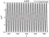
图2载车加速度变化图;Figure 2. The change diagram of the acceleration of the vehicle;
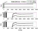
图3陀螺零次项误差估计图;Fig. 3 error estimation diagram of zero-order term of gyro;
图4陀螺X轴一次项误差估计图;Fig. 4 The error estimation diagram of the primary term of the X-axis of the gyro;
图5陀螺Y轴一次项误差估计图;Figure 5 is an error estimation diagram of the primary term of the Y-axis of the gyro;
图6陀螺Z轴一次项误差估计图;Fig. 6 The error estimation diagram of the primary term of the Z-axis of the gyro;
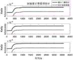
图7加速度计零次项误差估计图;Fig. 7 Error estimation diagram of zero-order term of accelerometer;
图8加速度计X轴一次项误差估计图;Fig. 8 Error estimation diagram of the primary term of the X-axis of the accelerometer;
图9加速度计Y轴一次项误差估计图;Fig. 9 Error estimation diagram of the primary term of the Y-axis of the accelerometer;
图10加速度计Z轴一次项误差估计图。Figure 10. The error estimation diagram of the Z axis of the accelerometer.
具体实施方式Detailed ways
本发明提供了一种惯性平台误差参数标定方法。该方法利用车载辅助传感器提供的比力、速度以及位置等基准信息作为观测量,与平台式惯性测量系统输出的比力、速度以及位置等信息做差,利用该差值与惯性器件各项误差参数之间的耦合关系通过最小二乘算法辨识出待估计误差参数。本发明能够通过跑车试验辨识出待估计的惯性平台误差参数,从而提高平台式惯性测量系统的精度,且此方法简单易行。The invention provides a method for calibrating error parameters of an inertial platform. This method uses the reference information such as specific force, speed and position provided by the on-board auxiliary sensor as the observation value, and makes a difference with the specific force, speed and position information output by the platform inertial measurement system, and uses the difference and various errors of the inertial device. The coupling relationship between the parameters is used to identify the error parameters to be estimated by the least squares algorithm. The invention can identify the inertial platform error parameters to be estimated through the sports car test, thereby improving the precision of the platform-type inertial measurement system, and the method is simple and easy to implement.
下面结合附图对本发明作出详细说明:The present invention is described in detail below in conjunction with the accompanying drawings:
一种惯性平台误差参数标定方法的流程图如附图1,方法主要步骤如下:A flowchart of an inertial platform error parameter calibration method is shown in Figure 1, and the main steps of the method are as follows:
步骤1、将惯性平台和高精度捷联式光纤惯性/GPS组合导航系统固定在统一安装基座上,然后再一起固定在载车上,使得惯性平台和组合导航系统之间的航向偏差及水平偏差为固定值;Step 1. Fix the inertial platform and the high-precision strapdown fiber optic inertial/GPS integrated navigation system on the unified installation base, and then fix them on the vehicle together to make the heading deviation and level between the inertial platform and the integrated navigation system. The deviation is a fixed value;
步骤2、启动惯性平台和组合导航设备,预热90分钟后,开始初始对准,经过30分钟初始对准结束后,记录惯性平台和组合导航设备的对准结果,并计算惯性平台与组合导航设备之间的航向和水平偏差,共进行3次对准,并将3次结果取平均值,作为惯性平台与组合导航设备之间的固定安装偏差;Step 2. Start the inertial platform and the integrated navigation equipment, start the initial alignment after 90 minutes of warm-up, and record the alignment results of the inertial platform and the integrated navigation equipment after 30 minutes of initial alignment, and calculate the inertial platform and the integrated navigation equipment. For the heading and horizontal deviation between the equipment, a total of 3 alignments are performed, and the average of the 3 results is taken as the fixed installation deviation between the inertial platform and the integrated navigation equipment;
步骤3、记录导航时间t、初始经度λ0、地球自转角速率ωie、高精度捷联式光纤惯性/GPS组合导航系统提供的经度λ、纬度L、比力基准信息fb、速度信息W、组合导航系统解算输出的捷联姿态矩阵
步骤4、利用步骤3得到的数据信息计算组合导航系统测量得到的载体比力信息在惯性系投影fi,将fi作为基准值;即:
其中
步骤5、利用平台式惯性测量系统加速度计测量值fp将陀螺漂移误差导致的平台失准角和加速度计测量误差进一步写成线性矩阵形式,即:
利用步骤3得到的fp和步骤4得到的fi构造观测量,Using the fp obtained in step 3 and the fi obtained in step 4 to construct the observations,
δfp=fp-fiδfp =fp -fi
进一步,将观测量与陀螺漂移误差导致的平台失准角和加速度计测量误差构成线性矩阵形式:Further, the observation amount, the platform misalignment angle and the accelerometer measurement error caused by the gyro drift error are formed into a linear matrix form:
δfp=HVXδfp =HV X
X是24维待辨识的陀螺仪和加速度计误差系数,HV是量测矩阵;X is the error coefficient of the 24-dimensional gyroscope and accelerometer to be identified, and HV is the measurement matrix;
其中


对转子陀螺仪静态漂移误差模型建立的数学模型如下所示:The mathematical model established for the static drift error model of the rotor gyroscope is as follows:


其中:

建立加速度计简化标定误差模型如下所示:The simplified calibration error model of the accelerometer is established as follows:


其中:δAax,δAay,δAaz分别为加速度计沿x,y,z轴向的总漂移误差。Where: δAax , δAay , δAaz are the total drift errors of the accelerometer along the x, y, and z axes, respectively.
步骤6、在获得观测信息建立观测方程后,利用递推最小二乘算法对各个误差参数进行辨识。递推最小二乘算法步骤为:Step 6: After the observation information is obtained and the observation equation is established, the recursive least squares algorithm is used to identify each error parameter. The steps of the recursive least squares algorithm are:
1.初始估计值如下:1. The initial estimates are as follows:
x0=E(x)x0 =E(x)

如果在观测值获取之前没有可利用的x的信息,那么P0=∞I。如果在观测值获取之前已经很好地获得x的信息,则P0=0。If no information for x is available before the observations are taken, then P0 =∞I. P0 =0 if the information for x is well obtained before the observation is taken.
2.对于k=1,2,...,执行如下步骤:2. For k=1,2,..., perform the following steps:
(a)获取观测值yk(a) Get the observed value yk
yk=Hkxk+vkyk =Hk xk +vk
(b)更新x的估计值和估计误差协方差矩阵Pk如下:(b) Update the estimated value of x and the estimated error covariance matrix Pk as follows:


其中,Rk是观测噪声协方差矩阵。where Rk is the observation noise covariancematrix .
步骤5中的建立惯性空间标定模型以及利用跑车试验标定误差参数。惯性空间标定模型方法如下:当平台式惯性测量系统工作在断调平工作模式下,其稳定平台将跟踪惯性坐标系。在这种工作模式下,选择比力信息在惯性坐标系的投影作为基准信息,建立该观测量与待标定惯性器件误差参数之间的耦合关系,即系统观测模型。In
X=[Kgox,Kxx,Kyx,Kzx,Kgoy,Kxy,Kyy,Kzy,Kgoz,Kxz,Kyz,Kzz,Kaox,Ka1x,θxz,θxy,Kaoy,Ka1y,θyz,θyx,Kaoz,Ka1z,θzy,θzx]T是24维待辨识的陀螺仪和加速度计误差系数;(HV)3×24是量测矩阵,相应的量测矩阵元素如表1所示(序号对应为列数,HV(i,j)对应第i行第j列元素):X=[Kgox ,Kxx ,Kyx ,Kzx ,Kgoy ,Kxy ,Kyy ,Kzy ,Kgoz ,Kxz ,Kyz ,Kzz ,Kaox ,Ka1x ,θxz ,θxy ,Kaoy ,Ka1y ,θyz ,θyx ,Kaoz ,Ka1z ,θzy ,θzx ]T is the 24-dimensional gyroscope and accelerometer error coefficient to be identified; (HV )3×24 is the measurement The corresponding measurement matrix elements are shown in Table 1 (the serial number corresponds to the number of columns, and HV (i, j) corresponds to the i-th row and j-th column elements):
表1量测矩阵(HV)3×24系数Table 1 Measurement matrix (HV )3×24 coefficients


其参数定义如下:Its parameters are defined as follows:
Kaox—与加速度无关的沿x轴向的误差系数;Kaox — error coefficient along the x-axis independent of acceleration;
Kaoy—与加速度无关的沿y轴向的误差系数;Kaoy — error coefficient along the y-axis independent of acceleration;
Kaoz—与加速度无关的沿z轴向的误差系数;Kaoz — the error coefficient along the z-axis independent of acceleration;
Ka1x,Kθyz,Kθzy—与x轴向加速度成比例的误差系数;Ka1x , Kθyz , Kθzy — an error coefficient proportional to the x-axis acceleration;
Ka1y,Kθxz,Kθzx—与y轴向加速度成比例的误差系数;Ka1y , Kθxz , Kθzx — an error coefficient proportional to the y-axis acceleration;
Ka1z,Kθyx,Kθxy—与z轴向加速度成比例的误差系数;Ka1z , Kθyx , Kθxy — an error coefficient proportional to the z-axial acceleration;
Kgox—与加速度无关的沿x轴向的陀螺仪漂移系数,即常值漂移;Kgox — gyroscope drift coefficient along the x-axis independent of acceleration, that is, constant drift;
Kgoy—与加速度无关的沿y轴向的陀螺仪漂移系数,即常值漂移;Kgoy — the gyroscope drift coefficient along the y-axis independent of acceleration, that is, constant drift;
Kgoz—与加速度无关的沿z轴向的陀螺仪漂移系数,即常值漂移;Kgoz — the gyroscope drift coefficient along the z-axis independent of acceleration, that is, constant drift;
Kxx,Kxy,Kxz—与x轴向加速度成比例的陀螺仪漂移系数;Kxx , Kxy , Kxz — the gyroscope drift coefficient proportional to the x-axis acceleration;
Kyx,Kyy,Kyz—与y轴向加速度成比例的陀螺仪漂移系数;Kyx , Kyy , Kyz — the gyroscope drift coefficient proportional to the y-axis acceleration;
Kzx,Kzy,Kzz—与z轴向加速度成比例的陀螺仪漂移系数;Kzx , Kzy , Kzz — the gyroscope drift coefficient proportional to the z-axis acceleration;
Wx,Wy,Wz分别为陀螺仪沿x,y,z轴向的速度。Wx , Wy , and Wz are the speeds of the gyroscope along the x, y, and z axes, respectively.
本发明的有益效果通过惯性空间标定仿真试验得以验证:The beneficial effects of the present invention are verified by the inertial space calibration simulation test:
仿真条件设置如下:The simulation conditions are set as follows:
(a)标定过程中初始方位为0°,载车做加减速剧烈运动5分钟后转向90°行驶,行驶5分钟后载车再次转向90°,行驶5分钟后载车继续转向90°行驶,然后行驶45分钟后1次试验结束。(a) During the calibration process, the initial orientation is 0°. After 5 minutes of intense acceleration and deceleration, the vehicle turns to 90°. After 5 minutes of driving, the vehicle turns to 90° again. After 5 minutes of driving, the vehicle continues to turn to 90°. Then one test ended after 45 minutes of driving.
(b)陀螺相关标定误差参数设置如表2所示。(b) The parameter settings of the gyro-related calibration error are shown in Table 2.
表2陀螺相关标定误差参数设置Table 2 Gyro-related calibration error parameter settings

(c)加速度计相关标定误差参数如表3所示。(c) The related calibration error parameters of the accelerometer are shown in Table 3.
表3加速度计相关标定误差参数设置Table 3 accelerometer related calibration error parameter settings

(d)器件噪声设置为:(d) The device noise is set to:
加速度计:方差强度为5*10-6g的白噪声;Accelerometer: white noise with variance intensity of 5*10-6 g;
陀螺:方差强度为0.003°/h的白噪声。Gyro: White noise with variance intensity of 0.003°/h.
(e)载车行驶过程中艏娓向加速度按下式所示变化:(e) The heading acceleration changes as follows:

仿真过程中,载车艏娓向加速度一段时间内变化情况如图2所示。在(a)~(e)试验条件下进行仿真试验,仿真试验过程中观测量X、Y、Z三轴比力输出分别存在均方差为0.001m/s2,0.002m/s2,0.001m/s2的随机噪声以及幅值为0.000105m/s2,0.000108m/s2,0.000105m/s2的常值偏差,利用最小二乘法对陀螺仪和加速度计各项待标定误差参数进行辨识,仿真结果如图3~10所示(其中,红色直线代表辨识结果,蓝色点线代表辨识误差)。重复进行10次仿真实验,按下式所示计算10次仿真结果相对均方误差,结果如表4所示(下表中均未带单位):During the simulation process, the change of the vehicle's heading acceleration over a period of time is shown in Figure 2. The simulation test is carried out under the test conditions (a) to (e). During the simulation test, the three-axis specific force output of the observed X, Y, and Z has a mean square deviation of 0.001m/s2 , 0.002m/s2 , and 0.001m respectively. /s2 random noise and constant deviations with amplitudes of 0.000105m/s2 , 0.000108m/s2 , 0.000105m/s2 , the least squares method is used to identify the error parameters to be calibrated for the gyroscope and accelerometer , the simulation results are shown in Figures 3 to 10 (where the red straight line represents the identification result, and the blue dotted line represents the identification error). Repeat the

其中,D0为真值,Di为第i次仿真试验辨识出的参数值,n为仿真试验次数10。Among them, D0 is the true value, Di is the parameter value identified in the ith simulation test, and n is the number of simulation tests 10.
表4仿真试验相对均方误差Table 4 Relative mean square error of simulation test


从仿真结果可以看出,陀螺的零次项和部分一次项以及加速度计的部分一次项可以快速估计出来,而加速度计零次项和陀螺及加速度计剩余一次项需要载车经过3次转弯后才能较好地辨识出来,从而验证了此发明的可行性。It can be seen from the simulation results that the zero-order term and some first-order terms of the gyroscope and some first-order terms of the accelerometer can be quickly estimated, while the zero-order term of the accelerometer and the remaining first-order terms of the gyro and accelerometer need to be carried by the vehicle after 3 turns can be better identified, thus verifying the feasibility of this invention.
Claims (4)
Translated fromChinese


Priority Applications (1)
| Application Number | Priority Date | Filing Date | Title |
|---|---|---|---|
| CN201910978606.5ACN112665610B (en) | 2019-10-15 | 2019-10-15 | Inertial platform error parameter calibration method |
Applications Claiming Priority (1)
| Application Number | Priority Date | Filing Date | Title |
|---|---|---|---|
| CN201910978606.5ACN112665610B (en) | 2019-10-15 | 2019-10-15 | Inertial platform error parameter calibration method |
Publications (2)
| Publication Number | Publication Date |
|---|---|
| CN112665610Atrue CN112665610A (en) | 2021-04-16 |
| CN112665610B CN112665610B (en) | 2023-01-03 |
Family
ID=75400157
Family Applications (1)
| Application Number | Title | Priority Date | Filing Date |
|---|---|---|---|
| CN201910978606.5AActiveCN112665610B (en) | 2019-10-15 | 2019-10-15 | Inertial platform error parameter calibration method |
Country Status (1)
| Country | Link |
|---|---|
| CN (1) | CN112665610B (en) |
Cited By (2)
| Publication number | Priority date | Publication date | Assignee | Title |
|---|---|---|---|---|
| CN113916219A (en)* | 2021-07-20 | 2022-01-11 | 北京航天控制仪器研究所 | Inertial measurement system error separation method based on centrifuge excitation |
| CN115755641A (en)* | 2022-10-28 | 2023-03-07 | 西安现代控制技术研究所 | Infrared guided weapon desktop semi-physical simulation system and simulation method |
Citations (21)
| Publication number | Priority date | Publication date | Assignee | Title |
|---|---|---|---|---|
| US5184304A (en)* | 1991-04-26 | 1993-02-02 | Litton Systems, Inc. | Fault-tolerant inertial navigation system |
| CN1908584A (en)* | 2006-08-23 | 2007-02-07 | 北京航空航天大学 | Method for determining initial status of strapdown inertial navigation system |
| CN101021879A (en)* | 2007-01-17 | 2007-08-22 | 南京航空航天大学 | Inertial measuring system error model demonstration test method |
| CN101187567A (en)* | 2007-12-18 | 2008-05-28 | 哈尔滨工程大学 | Determination of Initial Attitude of Fiber Optic Gyro Strapdown Inertial Navigation System Based on Doppler |
| CN101571394A (en)* | 2009-05-22 | 2009-11-04 | 哈尔滨工程大学 | Method for determining initial attitude of fiber strapdown inertial navigation system based on rotating mechanism |
| US20110137560A1 (en)* | 2009-12-03 | 2011-06-09 | Honeywell International Inc. | Method and system for latitude adaptive navigation quality estimation |
| CN102607595A (en)* | 2012-03-07 | 2012-07-25 | 北京航空航天大学 | Method for testing dynamic random drifting of strap-down flexible gyroscope by aid of laser Doppler velocimeter |
| CN102680000A (en)* | 2012-04-26 | 2012-09-19 | 北京航空航天大学 | Zero-velocity/course correction application online calibrating method for optical fiber strapdown inertial measuring unit |
| CN102759364A (en)* | 2012-04-26 | 2012-10-31 | 北京航空航天大学 | Specific-force sensitive error flight calibration method adopting GPS/SINS (Global Position System/Strapdown Inertial Navigation System) combination for flexible gyroscope |
| CN102865881A (en)* | 2012-03-06 | 2013-01-09 | 武汉大学 | Quick calibration method for inertial measurement unit |
| CN103076025A (en)* | 2013-01-07 | 2013-05-01 | 哈尔滨工程大学 | Constant error calibration method of fiber-optic gyroscope based on double-calculation program |
| CN103900571A (en)* | 2014-03-28 | 2014-07-02 | 哈尔滨工程大学 | Carrier attitude measurement method based on inertial coordinate system rotary type strapdown inertial navigation system |
| CN104764463A (en)* | 2015-03-19 | 2015-07-08 | 北京航天自动控制研究所 | Inertial platform leveling aiming error self-detection method |
| US20150285835A1 (en)* | 2013-12-23 | 2015-10-08 | InvenSense, Incorporated | Systems and methods for sensor calibration |
| CN106123921A (en)* | 2016-07-10 | 2016-11-16 | 北京工业大学 | Latitude the unknown Alignment Method of SINS under the conditions of dynamic disturbance |
| CN108168574A (en)* | 2017-11-23 | 2018-06-15 | 东南大学 | A kind of 8 position Strapdown Inertial Navigation System grade scaling methods based on speed observation |
| CN108680186A (en)* | 2018-05-17 | 2018-10-19 | 中国人民解放军海军工程大学 | Methods of Strapdown Inertial Navigation System nonlinear initial alignment method based on gravimeter platform |
| CN109084755A (en)* | 2018-06-14 | 2018-12-25 | 东南大学 | A kind of accelerometer bias estimation method based on gravity apparent velocity and parameter identification |
| CN109724599A (en)* | 2019-03-12 | 2019-05-07 | 哈尔滨工程大学 | A Robust Kalman Filter SINS/DVL Integrated Navigation Method Against Outliers |
| CN110031882A (en)* | 2018-08-02 | 2019-07-19 | 哈尔滨工程大学 | A kind of outer measurement information compensation method based on SINS/DVL integrated navigation system |
| CN110108300A (en)* | 2019-05-10 | 2019-08-09 | 哈尔滨工业大学 | A kind of IMU regular hexahedron scaling method based on horizontal triaxial turntable |
- 2019
- 2019-10-15CNCN201910978606.5Apatent/CN112665610B/enactiveActive
Patent Citations (21)
| Publication number | Priority date | Publication date | Assignee | Title |
|---|---|---|---|---|
| US5184304A (en)* | 1991-04-26 | 1993-02-02 | Litton Systems, Inc. | Fault-tolerant inertial navigation system |
| CN1908584A (en)* | 2006-08-23 | 2007-02-07 | 北京航空航天大学 | Method for determining initial status of strapdown inertial navigation system |
| CN101021879A (en)* | 2007-01-17 | 2007-08-22 | 南京航空航天大学 | Inertial measuring system error model demonstration test method |
| CN101187567A (en)* | 2007-12-18 | 2008-05-28 | 哈尔滨工程大学 | Determination of Initial Attitude of Fiber Optic Gyro Strapdown Inertial Navigation System Based on Doppler |
| CN101571394A (en)* | 2009-05-22 | 2009-11-04 | 哈尔滨工程大学 | Method for determining initial attitude of fiber strapdown inertial navigation system based on rotating mechanism |
| US20110137560A1 (en)* | 2009-12-03 | 2011-06-09 | Honeywell International Inc. | Method and system for latitude adaptive navigation quality estimation |
| CN102865881A (en)* | 2012-03-06 | 2013-01-09 | 武汉大学 | Quick calibration method for inertial measurement unit |
| CN102607595A (en)* | 2012-03-07 | 2012-07-25 | 北京航空航天大学 | Method for testing dynamic random drifting of strap-down flexible gyroscope by aid of laser Doppler velocimeter |
| CN102680000A (en)* | 2012-04-26 | 2012-09-19 | 北京航空航天大学 | Zero-velocity/course correction application online calibrating method for optical fiber strapdown inertial measuring unit |
| CN102759364A (en)* | 2012-04-26 | 2012-10-31 | 北京航空航天大学 | Specific-force sensitive error flight calibration method adopting GPS/SINS (Global Position System/Strapdown Inertial Navigation System) combination for flexible gyroscope |
| CN103076025A (en)* | 2013-01-07 | 2013-05-01 | 哈尔滨工程大学 | Constant error calibration method of fiber-optic gyroscope based on double-calculation program |
| US20150285835A1 (en)* | 2013-12-23 | 2015-10-08 | InvenSense, Incorporated | Systems and methods for sensor calibration |
| CN103900571A (en)* | 2014-03-28 | 2014-07-02 | 哈尔滨工程大学 | Carrier attitude measurement method based on inertial coordinate system rotary type strapdown inertial navigation system |
| CN104764463A (en)* | 2015-03-19 | 2015-07-08 | 北京航天自动控制研究所 | Inertial platform leveling aiming error self-detection method |
| CN106123921A (en)* | 2016-07-10 | 2016-11-16 | 北京工业大学 | Latitude the unknown Alignment Method of SINS under the conditions of dynamic disturbance |
| CN108168574A (en)* | 2017-11-23 | 2018-06-15 | 东南大学 | A kind of 8 position Strapdown Inertial Navigation System grade scaling methods based on speed observation |
| CN108680186A (en)* | 2018-05-17 | 2018-10-19 | 中国人民解放军海军工程大学 | Methods of Strapdown Inertial Navigation System nonlinear initial alignment method based on gravimeter platform |
| CN109084755A (en)* | 2018-06-14 | 2018-12-25 | 东南大学 | A kind of accelerometer bias estimation method based on gravity apparent velocity and parameter identification |
| CN110031882A (en)* | 2018-08-02 | 2019-07-19 | 哈尔滨工程大学 | A kind of outer measurement information compensation method based on SINS/DVL integrated navigation system |
| CN109724599A (en)* | 2019-03-12 | 2019-05-07 | 哈尔滨工程大学 | A Robust Kalman Filter SINS/DVL Integrated Navigation Method Against Outliers |
| CN110108300A (en)* | 2019-05-10 | 2019-08-09 | 哈尔滨工业大学 | A kind of IMU regular hexahedron scaling method based on horizontal triaxial turntable |
Non-Patent Citations (5)
| Title |
|---|
| BAO GUIQING等: "Initial Alignment of Strap-down Inertial Navigation System Aided by Doppler Velocity Log", 《ELECTRONICS OPTICS & CONTROL》* |
| LU ZHANG等: "DVL-Aided SINS In-Motion Alignment Filter Based on a Novel Nonlinear Attitude Error Model", 《IEEE ACCESS》* |
| 刘瑞方: "热环境下激光陀螺捷联惯性系统误差机理及建模方法研究", 《中国优秀博硕士学位论文全文数据库(硕士)工程科技Ⅱ辑》* |
| 段江锋: "光纤陀螺罗经研究", 《中国优秀博硕士学位论文全文数据库(硕士)工程科技Ⅱ辑》* |
| 陈才等: "基于离心机测试的惯导平台误差系数辨识研究", 《系统工程与电子技术》* |
Cited By (2)
| Publication number | Priority date | Publication date | Assignee | Title |
|---|---|---|---|---|
| CN113916219A (en)* | 2021-07-20 | 2022-01-11 | 北京航天控制仪器研究所 | Inertial measurement system error separation method based on centrifuge excitation |
| CN115755641A (en)* | 2022-10-28 | 2023-03-07 | 西安现代控制技术研究所 | Infrared guided weapon desktop semi-physical simulation system and simulation method |
Also Published As
| Publication number | Publication date |
|---|---|
| CN112665610B (en) | 2023-01-03 |
Similar Documents
| Publication | Publication Date | Title |
|---|---|---|
| CN108168574B (en) | An 8-Position Strapdown Inertial Navigation System-Level Calibration Method Based on Velocity Observation | |
| Gao et al. | A self-calibration method for accelerometer nonlinearity errors in triaxis rotational inertial navigation system | |
| CN110887507B (en) | A Method of Rapidly Estimating All Zero Bias of Inertial Measurement Unit | |
| CN112595350B (en) | Automatic calibration method and terminal for inertial navigation system | |
| Liu et al. | Fast self-alignment technology for hybrid inertial navigation systems based on a new two-position analytic method | |
| CN110006450A (en) | A calibration method of laser strapdown inertial navigation system on horizontal three-axis turntable | |
| Deng et al. | Analysis and calibration of the nonorthogonal angle in dual-axis rotational INS | |
| CN106969783B (en) | A Single-axis Rotation Fast Calibration Technology Based on Fiber Optic Gyroscope Inertial Navigation | |
| CN107655493B (en) | SINS six-position system-level calibration method for fiber-optic gyroscope | |
| CN115143993B (en) | G-sensitivity error calibration method for laser gyro inertial navigation system based on three-axis turntable | |
| CN106482746B (en) | An accelerometer inner lever arm calibration and compensation method for hybrid inertial navigation system | |
| CN109029500A (en) | A kind of dual-axis rotation modulating system population parameter self-calibrating method | |
| CN101246023A (en) | Closed-loop Calibration Method of Micromachined Gyro Inertial Measurement Components | |
| CN108593965B (en) | A Mooring State Calibration Method of Accelerometer Based on Specific Force Modulus and Inertial Stability | |
| GB2375173A (en) | Long-term navigation method and device | |
| CN106767915A (en) | A kind of used group scaling method of optical fiber of carrier rocket with redundancy inclined shaft | |
| Wang et al. | An improve hybrid calibration scheme for strapdown inertial navigation system | |
| Li et al. | Integrated calibration method for dithered RLG POS using a hybrid analytic/Kalman filter approach | |
| Liu et al. | Analysis and improvement of attitude output accuracy in tri-axis rotational inertial navigation system | |
| CN112665610B (en) | Inertial platform error parameter calibration method | |
| CN114877915B (en) | Device and method for calibrating g sensitivity error of laser gyro inertia measurement assembly | |
| Xu et al. | A self-calibration method of inner lever arms for dual-axis rotation inertial navigation systems | |
| CN101561292A (en) | Method and device for calibrating size effect error of accelerometer | |
| Li et al. | An efficient system-level calibration method for a high-precision RLG RINS considering the G-sensitive misalignment | |
| Fu et al. | Multiposition alignment for rotational INS based on real-time estimation of inner lever arms |
Legal Events
| Date | Code | Title | Description |
|---|---|---|---|
| PB01 | Publication | ||
| PB01 | Publication | ||
| SE01 | Entry into force of request for substantive examination | ||
| SE01 | Entry into force of request for substantive examination | ||
| GR01 | Patent grant | ||
| GR01 | Patent grant | ||
| TR01 | Transfer of patent right | Effective date of registration:20230626 Address after:210042 Xuanwu Road, Xuanwu District, Nanjing, Jiangsu 699-1 Patentee after:NANJING XINDONGTAI INFORMATION TECHNOLOGY CO.,LTD. Address before:150001 Intellectual Property Office, Harbin Engineering University science and technology office, 145 Nantong Avenue, Nangang District, Harbin, Heilongjiang Patentee before:HARBIN ENGINEERING University | |
| TR01 | Transfer of patent right | ||
| TR01 | Transfer of patent right | Effective date of registration:20230728 Address after:150000 floor 2, East unit 22, Tianping Road, building 2D, dui'e Park, Yingbin Road concentration area, high tech Industrial Development Zone, Harbin, Heilongjiang Province Patentee after:HARBIN HATRAN NAVIGATION TECHNOLOGY Co.,Ltd. Address before:210042 Xuanwu Road, Xuanwu District, Nanjing, Jiangsu 699-1 Patentee before:NANJING XINDONGTAI INFORMATION TECHNOLOGY CO.,LTD. | |
| TR01 | Transfer of patent right |