CN112601612B - System and method for inspecting microfluidic rotor devices - Google Patents
System and method for inspecting microfluidic rotor devicesDownload PDFInfo
- Publication number
- CN112601612B CN112601612BCN201980055831.XACN201980055831ACN112601612BCN 112601612 BCN112601612 BCN 112601612BCN 201980055831 ACN201980055831 ACN 201980055831ACN 112601612 BCN112601612 BCN 112601612B
- Authority
- CN
- China
- Prior art keywords
- rotor
- layer
- reagent
- microfluidic
- fluid
- Prior art date
- Legal status (The legal status is an assumption and is not a legal conclusion. Google has not performed a legal analysis and makes no representation as to the accuracy of the status listed.)
- Active
Links
Images


Classifications
- B—PERFORMING OPERATIONS; TRANSPORTING
- B01—PHYSICAL OR CHEMICAL PROCESSES OR APPARATUS IN GENERAL
- B01L—CHEMICAL OR PHYSICAL LABORATORY APPARATUS FOR GENERAL USE
- B01L3/00—Containers or dishes for laboratory use, e.g. laboratory glassware; Droppers
- B01L3/50—Containers for the purpose of retaining a material to be analysed, e.g. test tubes
- B01L3/502—Containers for the purpose of retaining a material to be analysed, e.g. test tubes with fluid transport, e.g. in multi-compartment structures
- B01L3/5027—Containers for the purpose of retaining a material to be analysed, e.g. test tubes with fluid transport, e.g. in multi-compartment structures by integrated microfluidic structures, i.e. dimensions of channels and chambers are such that surface tension forces are important, e.g. lab-on-a-chip
- B01L3/502707—Containers for the purpose of retaining a material to be analysed, e.g. test tubes with fluid transport, e.g. in multi-compartment structures by integrated microfluidic structures, i.e. dimensions of channels and chambers are such that surface tension forces are important, e.g. lab-on-a-chip characterised by the manufacture of the container or its components
- G—PHYSICS
- G06—COMPUTING OR CALCULATING; COUNTING
- G06T—IMAGE DATA PROCESSING OR GENERATION, IN GENERAL
- G06T7/00—Image analysis
- G06T7/0002—Inspection of images, e.g. flaw detection
- G06T7/0004—Industrial image inspection
- B—PERFORMING OPERATIONS; TRANSPORTING
- B01—PHYSICAL OR CHEMICAL PROCESSES OR APPARATUS IN GENERAL
- B01L—CHEMICAL OR PHYSICAL LABORATORY APPARATUS FOR GENERAL USE
- B01L3/00—Containers or dishes for laboratory use, e.g. laboratory glassware; Droppers
- B01L3/50—Containers for the purpose of retaining a material to be analysed, e.g. test tubes
- B01L3/502—Containers for the purpose of retaining a material to be analysed, e.g. test tubes with fluid transport, e.g. in multi-compartment structures
- B01L3/5021—Test tubes specially adapted for centrifugation purposes
- B—PERFORMING OPERATIONS; TRANSPORTING
- B01—PHYSICAL OR CHEMICAL PROCESSES OR APPARATUS IN GENERAL
- B01L—CHEMICAL OR PHYSICAL LABORATORY APPARATUS FOR GENERAL USE
- B01L3/00—Containers or dishes for laboratory use, e.g. laboratory glassware; Droppers
- B01L3/50—Containers for the purpose of retaining a material to be analysed, e.g. test tubes
- B01L3/502—Containers for the purpose of retaining a material to be analysed, e.g. test tubes with fluid transport, e.g. in multi-compartment structures
- B01L3/5027—Containers for the purpose of retaining a material to be analysed, e.g. test tubes with fluid transport, e.g. in multi-compartment structures by integrated microfluidic structures, i.e. dimensions of channels and chambers are such that surface tension forces are important, e.g. lab-on-a-chip
- B01L3/502715—Containers for the purpose of retaining a material to be analysed, e.g. test tubes with fluid transport, e.g. in multi-compartment structures by integrated microfluidic structures, i.e. dimensions of channels and chambers are such that surface tension forces are important, e.g. lab-on-a-chip characterised by interfacing components, e.g. fluidic, electrical, optical or mechanical interfaces
- B—PERFORMING OPERATIONS; TRANSPORTING
- B29—WORKING OF PLASTICS; WORKING OF SUBSTANCES IN A PLASTIC STATE IN GENERAL
- B29C—SHAPING OR JOINING OF PLASTICS; SHAPING OF MATERIAL IN A PLASTIC STATE, NOT OTHERWISE PROVIDED FOR; AFTER-TREATMENT OF THE SHAPED PRODUCTS, e.g. REPAIRING
- B29C45/00—Injection moulding, i.e. forcing the required volume of moulding material through a nozzle into a closed mould; Apparatus therefor
- B29C45/14—Injection moulding, i.e. forcing the required volume of moulding material through a nozzle into a closed mould; Apparatus therefor incorporating preformed parts or layers, e.g. injection moulding around inserts or for coating articles
- B29C45/14467—Joining articles or parts of a single article
- B—PERFORMING OPERATIONS; TRANSPORTING
- B29—WORKING OF PLASTICS; WORKING OF SUBSTANCES IN A PLASTIC STATE IN GENERAL
- B29C—SHAPING OR JOINING OF PLASTICS; SHAPING OF MATERIAL IN A PLASTIC STATE, NOT OTHERWISE PROVIDED FOR; AFTER-TREATMENT OF THE SHAPED PRODUCTS, e.g. REPAIRING
- B29C65/00—Joining or sealing of preformed parts, e.g. welding of plastics materials; Apparatus therefor
- B29C65/02—Joining or sealing of preformed parts, e.g. welding of plastics materials; Apparatus therefor by heating, with or without pressure
- B29C65/14—Joining or sealing of preformed parts, e.g. welding of plastics materials; Apparatus therefor by heating, with or without pressure using wave energy, i.e. electromagnetic radiation, or particle radiation
- B29C65/1403—Joining or sealing of preformed parts, e.g. welding of plastics materials; Apparatus therefor by heating, with or without pressure using wave energy, i.e. electromagnetic radiation, or particle radiation characterised by the type of electromagnetic or particle radiation
- B29C65/1412—Infrared [IR] radiation
- B—PERFORMING OPERATIONS; TRANSPORTING
- B29—WORKING OF PLASTICS; WORKING OF SUBSTANCES IN A PLASTIC STATE IN GENERAL
- B29C—SHAPING OR JOINING OF PLASTICS; SHAPING OF MATERIAL IN A PLASTIC STATE, NOT OTHERWISE PROVIDED FOR; AFTER-TREATMENT OF THE SHAPED PRODUCTS, e.g. REPAIRING
- B29C65/00—Joining or sealing of preformed parts, e.g. welding of plastics materials; Apparatus therefor
- B29C65/02—Joining or sealing of preformed parts, e.g. welding of plastics materials; Apparatus therefor by heating, with or without pressure
- B29C65/14—Joining or sealing of preformed parts, e.g. welding of plastics materials; Apparatus therefor by heating, with or without pressure using wave energy, i.e. electromagnetic radiation, or particle radiation
- B29C65/1477—Joining or sealing of preformed parts, e.g. welding of plastics materials; Apparatus therefor by heating, with or without pressure using wave energy, i.e. electromagnetic radiation, or particle radiation making use of an absorber or impact modifier
- B—PERFORMING OPERATIONS; TRANSPORTING
- B29—WORKING OF PLASTICS; WORKING OF SUBSTANCES IN A PLASTIC STATE IN GENERAL
- B29C—SHAPING OR JOINING OF PLASTICS; SHAPING OF MATERIAL IN A PLASTIC STATE, NOT OTHERWISE PROVIDED FOR; AFTER-TREATMENT OF THE SHAPED PRODUCTS, e.g. REPAIRING
- B29C65/00—Joining or sealing of preformed parts, e.g. welding of plastics materials; Apparatus therefor
- B29C65/02—Joining or sealing of preformed parts, e.g. welding of plastics materials; Apparatus therefor by heating, with or without pressure
- B29C65/14—Joining or sealing of preformed parts, e.g. welding of plastics materials; Apparatus therefor by heating, with or without pressure using wave energy, i.e. electromagnetic radiation, or particle radiation
- B29C65/1496—Joining or sealing of preformed parts, e.g. welding of plastics materials; Apparatus therefor by heating, with or without pressure using wave energy, i.e. electromagnetic radiation, or particle radiation making use of masks
- B—PERFORMING OPERATIONS; TRANSPORTING
- B29—WORKING OF PLASTICS; WORKING OF SUBSTANCES IN A PLASTIC STATE IN GENERAL
- B29C—SHAPING OR JOINING OF PLASTICS; SHAPING OF MATERIAL IN A PLASTIC STATE, NOT OTHERWISE PROVIDED FOR; AFTER-TREATMENT OF THE SHAPED PRODUCTS, e.g. REPAIRING
- B29C65/00—Joining or sealing of preformed parts, e.g. welding of plastics materials; Apparatus therefor
- B29C65/02—Joining or sealing of preformed parts, e.g. welding of plastics materials; Apparatus therefor by heating, with or without pressure
- B29C65/14—Joining or sealing of preformed parts, e.g. welding of plastics materials; Apparatus therefor by heating, with or without pressure using wave energy, i.e. electromagnetic radiation, or particle radiation
- B29C65/16—Laser beams
- B29C65/1603—Laser beams characterised by the type of electromagnetic radiation
- B29C65/1612—Infrared [IR] radiation, e.g. by infrared lasers
- B—PERFORMING OPERATIONS; TRANSPORTING
- B29—WORKING OF PLASTICS; WORKING OF SUBSTANCES IN A PLASTIC STATE IN GENERAL
- B29C—SHAPING OR JOINING OF PLASTICS; SHAPING OF MATERIAL IN A PLASTIC STATE, NOT OTHERWISE PROVIDED FOR; AFTER-TREATMENT OF THE SHAPED PRODUCTS, e.g. REPAIRING
- B29C65/00—Joining or sealing of preformed parts, e.g. welding of plastics materials; Apparatus therefor
- B29C65/02—Joining or sealing of preformed parts, e.g. welding of plastics materials; Apparatus therefor by heating, with or without pressure
- B29C65/14—Joining or sealing of preformed parts, e.g. welding of plastics materials; Apparatus therefor by heating, with or without pressure using wave energy, i.e. electromagnetic radiation, or particle radiation
- B29C65/16—Laser beams
- B29C65/1696—Laser beams making use of masks
- B—PERFORMING OPERATIONS; TRANSPORTING
- B29—WORKING OF PLASTICS; WORKING OF SUBSTANCES IN A PLASTIC STATE IN GENERAL
- B29C—SHAPING OR JOINING OF PLASTICS; SHAPING OF MATERIAL IN A PLASTIC STATE, NOT OTHERWISE PROVIDED FOR; AFTER-TREATMENT OF THE SHAPED PRODUCTS, e.g. REPAIRING
- B29C65/00—Joining or sealing of preformed parts, e.g. welding of plastics materials; Apparatus therefor
- B29C65/70—Joining or sealing of preformed parts, e.g. welding of plastics materials; Apparatus therefor by moulding
- B—PERFORMING OPERATIONS; TRANSPORTING
- B29—WORKING OF PLASTICS; WORKING OF SUBSTANCES IN A PLASTIC STATE IN GENERAL
- B29C—SHAPING OR JOINING OF PLASTICS; SHAPING OF MATERIAL IN A PLASTIC STATE, NOT OTHERWISE PROVIDED FOR; AFTER-TREATMENT OF THE SHAPED PRODUCTS, e.g. REPAIRING
- B29C65/00—Joining or sealing of preformed parts, e.g. welding of plastics materials; Apparatus therefor
- B29C65/82—Testing the joint
- B—PERFORMING OPERATIONS; TRANSPORTING
- B29—WORKING OF PLASTICS; WORKING OF SUBSTANCES IN A PLASTIC STATE IN GENERAL
- B29C—SHAPING OR JOINING OF PLASTICS; SHAPING OF MATERIAL IN A PLASTIC STATE, NOT OTHERWISE PROVIDED FOR; AFTER-TREATMENT OF THE SHAPED PRODUCTS, e.g. REPAIRING
- B29C66/00—General aspects of processes or apparatus for joining preformed parts
- B29C66/01—General aspects dealing with the joint area or with the area to be joined
- B29C66/05—Particular design of joint configurations
- B29C66/10—Particular design of joint configurations particular design of the joint cross-sections
- B29C66/11—Joint cross-sections comprising a single joint-segment, i.e. one of the parts to be joined comprising a single joint-segment in the joint cross-section
- B—PERFORMING OPERATIONS; TRANSPORTING
- B29—WORKING OF PLASTICS; WORKING OF SUBSTANCES IN A PLASTIC STATE IN GENERAL
- B29C—SHAPING OR JOINING OF PLASTICS; SHAPING OF MATERIAL IN A PLASTIC STATE, NOT OTHERWISE PROVIDED FOR; AFTER-TREATMENT OF THE SHAPED PRODUCTS, e.g. REPAIRING
- B29C66/00—General aspects of processes or apparatus for joining preformed parts
- B29C66/50—General aspects of joining tubular articles; General aspects of joining long products, i.e. bars or profiled elements; General aspects of joining single elements to tubular articles, hollow articles or bars; General aspects of joining several hollow-preforms to form hollow or tubular articles
- B29C66/51—Joining tubular articles, profiled elements or bars; Joining single elements to tubular articles, hollow articles or bars; Joining several hollow-preforms to form hollow or tubular articles
- B29C66/53—Joining single elements to tubular articles, hollow articles or bars
- B29C66/534—Joining single elements to open ends of tubular or hollow articles or to the ends of bars
- B29C66/5346—Joining single elements to open ends of tubular or hollow articles or to the ends of bars said single elements being substantially flat
- B29C66/53461—Joining single elements to open ends of tubular or hollow articles or to the ends of bars said single elements being substantially flat joining substantially flat covers and/or substantially flat bottoms to open ends of container bodies
- B—PERFORMING OPERATIONS; TRANSPORTING
- B29—WORKING OF PLASTICS; WORKING OF SUBSTANCES IN A PLASTIC STATE IN GENERAL
- B29C—SHAPING OR JOINING OF PLASTICS; SHAPING OF MATERIAL IN A PLASTIC STATE, NOT OTHERWISE PROVIDED FOR; AFTER-TREATMENT OF THE SHAPED PRODUCTS, e.g. REPAIRING
- B29C66/00—General aspects of processes or apparatus for joining preformed parts
- B29C66/50—General aspects of joining tubular articles; General aspects of joining long products, i.e. bars or profiled elements; General aspects of joining single elements to tubular articles, hollow articles or bars; General aspects of joining several hollow-preforms to form hollow or tubular articles
- B29C66/51—Joining tubular articles, profiled elements or bars; Joining single elements to tubular articles, hollow articles or bars; Joining several hollow-preforms to form hollow or tubular articles
- B29C66/54—Joining several hollow-preforms, e.g. half-shells, to form hollow articles, e.g. for making balls, containers; Joining several hollow-preforms, e.g. half-cylinders, to form tubular articles
- B29C66/541—Joining several hollow-preforms, e.g. half-shells, to form hollow articles, e.g. for making balls, containers; Joining several hollow-preforms, e.g. half-cylinders, to form tubular articles a substantially flat extra element being placed between and clamped by the joined hollow-preforms
- B29C66/5414—Joining several hollow-preforms, e.g. half-shells, to form hollow articles, e.g. for making balls, containers; Joining several hollow-preforms, e.g. half-cylinders, to form tubular articles a substantially flat extra element being placed between and clamped by the joined hollow-preforms said substantially flat extra element being rigid, e.g. a plate
- B—PERFORMING OPERATIONS; TRANSPORTING
- B29—WORKING OF PLASTICS; WORKING OF SUBSTANCES IN A PLASTIC STATE IN GENERAL
- B29C—SHAPING OR JOINING OF PLASTICS; SHAPING OF MATERIAL IN A PLASTIC STATE, NOT OTHERWISE PROVIDED FOR; AFTER-TREATMENT OF THE SHAPED PRODUCTS, e.g. REPAIRING
- B29C66/00—General aspects of processes or apparatus for joining preformed parts
- B29C66/70—General aspects of processes or apparatus for joining preformed parts characterised by the composition, physical properties or the structure of the material of the parts to be joined; Joining with non-plastics material
- B29C66/73—General aspects of processes or apparatus for joining preformed parts characterised by the composition, physical properties or the structure of the material of the parts to be joined; Joining with non-plastics material characterised by the intensive physical properties of the material of the parts to be joined, by the optical properties of the material of the parts to be joined, by the extensive physical properties of the parts to be joined, by the state of the material of the parts to be joined or by the material of the parts to be joined being a thermoplastic or a thermoset
- B29C66/739—General aspects of processes or apparatus for joining preformed parts characterised by the composition, physical properties or the structure of the material of the parts to be joined; Joining with non-plastics material characterised by the intensive physical properties of the material of the parts to be joined, by the optical properties of the material of the parts to be joined, by the extensive physical properties of the parts to be joined, by the state of the material of the parts to be joined or by the material of the parts to be joined being a thermoplastic or a thermoset characterised by the material of the parts to be joined being a thermoplastic or a thermoset
- B29C66/7392—General aspects of processes or apparatus for joining preformed parts characterised by the composition, physical properties or the structure of the material of the parts to be joined; Joining with non-plastics material characterised by the intensive physical properties of the material of the parts to be joined, by the optical properties of the material of the parts to be joined, by the extensive physical properties of the parts to be joined, by the state of the material of the parts to be joined or by the material of the parts to be joined being a thermoplastic or a thermoset characterised by the material of the parts to be joined being a thermoplastic or a thermoset characterised by the material of at least one of the parts being a thermoplastic
- B29C66/73921—General aspects of processes or apparatus for joining preformed parts characterised by the composition, physical properties or the structure of the material of the parts to be joined; Joining with non-plastics material characterised by the intensive physical properties of the material of the parts to be joined, by the optical properties of the material of the parts to be joined, by the extensive physical properties of the parts to be joined, by the state of the material of the parts to be joined or by the material of the parts to be joined being a thermoplastic or a thermoset characterised by the material of the parts to be joined being a thermoplastic or a thermoset characterised by the material of at least one of the parts being a thermoplastic characterised by the materials of both parts being thermoplastics
- G—PHYSICS
- G01—MEASURING; TESTING
- G01N—INVESTIGATING OR ANALYSING MATERIALS BY DETERMINING THEIR CHEMICAL OR PHYSICAL PROPERTIES
- G01N21/00—Investigating or analysing materials by the use of optical means, i.e. using sub-millimetre waves, infrared, visible or ultraviolet light
- G01N21/01—Arrangements or apparatus for facilitating the optical investigation
- G01N21/03—Cuvette constructions
- G01N21/07—Centrifugal type cuvettes
- G—PHYSICS
- G01—MEASURING; TESTING
- G01N—INVESTIGATING OR ANALYSING MATERIALS BY DETERMINING THEIR CHEMICAL OR PHYSICAL PROPERTIES
- G01N21/00—Investigating or analysing materials by the use of optical means, i.e. using sub-millimetre waves, infrared, visible or ultraviolet light
- G01N21/17—Systems in which incident light is modified in accordance with the properties of the material investigated
- G01N21/25—Colour; Spectral properties, i.e. comparison of effect of material on the light at two or more different wavelengths or wavelength bands
- G01N21/251—Colorimeters; Construction thereof
- G01N21/253—Colorimeters; Construction thereof for batch operation, i.e. multisample apparatus
- G—PHYSICS
- G01—MEASURING; TESTING
- G01N—INVESTIGATING OR ANALYSING MATERIALS BY DETERMINING THEIR CHEMICAL OR PHYSICAL PROPERTIES
- G01N27/00—Investigating or analysing materials by the use of electric, electrochemical, or magnetic means
- G01N27/02—Investigating or analysing materials by the use of electric, electrochemical, or magnetic means by investigating impedance
- G01N27/04—Investigating or analysing materials by the use of electric, electrochemical, or magnetic means by investigating impedance by investigating resistance
- G01N27/06—Investigating or analysing materials by the use of electric, electrochemical, or magnetic means by investigating impedance by investigating resistance of a liquid
- G01N27/07—Construction of measuring vessels; Electrodes therefor
- G—PHYSICS
- G01—MEASURING; TESTING
- G01N—INVESTIGATING OR ANALYSING MATERIALS BY DETERMINING THEIR CHEMICAL OR PHYSICAL PROPERTIES
- G01N35/00—Automatic analysis not limited to methods or materials provided for in any single one of groups G01N1/00 - G01N33/00; Handling materials therefor
- G01N35/00029—Automatic analysis not limited to methods or materials provided for in any single one of groups G01N1/00 - G01N33/00; Handling materials therefor provided with flat sample substrates, e.g. slides
- G01N35/00069—Automatic analysis not limited to methods or materials provided for in any single one of groups G01N1/00 - G01N33/00; Handling materials therefor provided with flat sample substrates, e.g. slides whereby the sample substrate is of the bio-disk type, i.e. having the format of an optical disk
- G—PHYSICS
- G01—MEASURING; TESTING
- G01N—INVESTIGATING OR ANALYSING MATERIALS BY DETERMINING THEIR CHEMICAL OR PHYSICAL PROPERTIES
- G01N35/00—Automatic analysis not limited to methods or materials provided for in any single one of groups G01N1/00 - G01N33/00; Handling materials therefor
- G01N35/00584—Control arrangements for automatic analysers
- G01N35/00594—Quality control, including calibration or testing of components of the analyser
- G01N35/00613—Quality control
- G01N35/00663—Quality control of consumables
- H—ELECTRICITY
- H04—ELECTRIC COMMUNICATION TECHNIQUE
- H04N—PICTORIAL COMMUNICATION, e.g. TELEVISION
- H04N23/00—Cameras or camera modules comprising electronic image sensors; Control thereof
- H04N23/56—Cameras or camera modules comprising electronic image sensors; Control thereof provided with illuminating means
- H—ELECTRICITY
- H04—ELECTRIC COMMUNICATION TECHNIQUE
- H04N—PICTORIAL COMMUNICATION, e.g. TELEVISION
- H04N23/00—Cameras or camera modules comprising electronic image sensors; Control thereof
- H04N23/60—Control of cameras or camera modules
- H04N23/695—Control of camera direction for changing a field of view, e.g. pan, tilt or based on tracking of objects
- B—PERFORMING OPERATIONS; TRANSPORTING
- B01—PHYSICAL OR CHEMICAL PROCESSES OR APPARATUS IN GENERAL
- B01L—CHEMICAL OR PHYSICAL LABORATORY APPARATUS FOR GENERAL USE
- B01L2200/00—Solutions for specific problems relating to chemical or physical laboratory apparatus
- B01L2200/02—Adapting objects or devices to another
- B01L2200/025—Align devices or objects to ensure defined positions relative to each other
- B—PERFORMING OPERATIONS; TRANSPORTING
- B01—PHYSICAL OR CHEMICAL PROCESSES OR APPARATUS IN GENERAL
- B01L—CHEMICAL OR PHYSICAL LABORATORY APPARATUS FOR GENERAL USE
- B01L2200/00—Solutions for specific problems relating to chemical or physical laboratory apparatus
- B01L2200/06—Fluid handling related problems
- B01L2200/0605—Metering of fluids
- B—PERFORMING OPERATIONS; TRANSPORTING
- B01—PHYSICAL OR CHEMICAL PROCESSES OR APPARATUS IN GENERAL
- B01L—CHEMICAL OR PHYSICAL LABORATORY APPARATUS FOR GENERAL USE
- B01L2200/00—Solutions for specific problems relating to chemical or physical laboratory apparatus
- B01L2200/06—Fluid handling related problems
- B01L2200/0689—Sealing
- B—PERFORMING OPERATIONS; TRANSPORTING
- B01—PHYSICAL OR CHEMICAL PROCESSES OR APPARATUS IN GENERAL
- B01L—CHEMICAL OR PHYSICAL LABORATORY APPARATUS FOR GENERAL USE
- B01L2200/00—Solutions for specific problems relating to chemical or physical laboratory apparatus
- B01L2200/14—Process control and prevention of errors
- B01L2200/143—Quality control, feedback systems
- B—PERFORMING OPERATIONS; TRANSPORTING
- B01—PHYSICAL OR CHEMICAL PROCESSES OR APPARATUS IN GENERAL
- B01L—CHEMICAL OR PHYSICAL LABORATORY APPARATUS FOR GENERAL USE
- B01L2300/00—Additional constructional details
- B01L2300/02—Identification, exchange or storage of information
- B01L2300/023—Sending and receiving of information, e.g. using bluetooth
- B—PERFORMING OPERATIONS; TRANSPORTING
- B01—PHYSICAL OR CHEMICAL PROCESSES OR APPARATUS IN GENERAL
- B01L—CHEMICAL OR PHYSICAL LABORATORY APPARATUS FOR GENERAL USE
- B01L2300/00—Additional constructional details
- B01L2300/06—Auxiliary integrated devices, integrated components
- B01L2300/0627—Sensor or part of a sensor is integrated
- B—PERFORMING OPERATIONS; TRANSPORTING
- B01—PHYSICAL OR CHEMICAL PROCESSES OR APPARATUS IN GENERAL
- B01L—CHEMICAL OR PHYSICAL LABORATORY APPARATUS FOR GENERAL USE
- B01L2300/00—Additional constructional details
- B01L2300/08—Geometry, shape and general structure
- B01L2300/0803—Disc shape
- B01L2300/0806—Standardised forms, e.g. compact disc [CD] format
- B—PERFORMING OPERATIONS; TRANSPORTING
- B01—PHYSICAL OR CHEMICAL PROCESSES OR APPARATUS IN GENERAL
- B01L—CHEMICAL OR PHYSICAL LABORATORY APPARATUS FOR GENERAL USE
- B01L2300/00—Additional constructional details
- B01L2300/08—Geometry, shape and general structure
- B01L2300/0809—Geometry, shape and general structure rectangular shaped
- B—PERFORMING OPERATIONS; TRANSPORTING
- B01—PHYSICAL OR CHEMICAL PROCESSES OR APPARATUS IN GENERAL
- B01L—CHEMICAL OR PHYSICAL LABORATORY APPARATUS FOR GENERAL USE
- B01L2300/00—Additional constructional details
- B01L2300/16—Surface properties and coatings
- B01L2300/168—Specific optical properties, e.g. reflective coatings
- B—PERFORMING OPERATIONS; TRANSPORTING
- B01—PHYSICAL OR CHEMICAL PROCESSES OR APPARATUS IN GENERAL
- B01L—CHEMICAL OR PHYSICAL LABORATORY APPARATUS FOR GENERAL USE
- B01L2400/00—Moving or stopping fluids
- B01L2400/04—Moving fluids with specific forces or mechanical means
- B01L2400/0403—Moving fluids with specific forces or mechanical means specific forces
- B01L2400/0409—Moving fluids with specific forces or mechanical means specific forces centrifugal forces
- B—PERFORMING OPERATIONS; TRANSPORTING
- B29—WORKING OF PLASTICS; WORKING OF SUBSTANCES IN A PLASTIC STATE IN GENERAL
- B29C—SHAPING OR JOINING OF PLASTICS; SHAPING OF MATERIAL IN A PLASTIC STATE, NOT OTHERWISE PROVIDED FOR; AFTER-TREATMENT OF THE SHAPED PRODUCTS, e.g. REPAIRING
- B29C65/00—Joining or sealing of preformed parts, e.g. welding of plastics materials; Apparatus therefor
- B29C65/02—Joining or sealing of preformed parts, e.g. welding of plastics materials; Apparatus therefor by heating, with or without pressure
- B29C65/08—Joining or sealing of preformed parts, e.g. welding of plastics materials; Apparatus therefor by heating, with or without pressure using ultrasonic vibrations
- B—PERFORMING OPERATIONS; TRANSPORTING
- B29—WORKING OF PLASTICS; WORKING OF SUBSTANCES IN A PLASTIC STATE IN GENERAL
- B29C—SHAPING OR JOINING OF PLASTICS; SHAPING OF MATERIAL IN A PLASTIC STATE, NOT OTHERWISE PROVIDED FOR; AFTER-TREATMENT OF THE SHAPED PRODUCTS, e.g. REPAIRING
- B29C65/00—Joining or sealing of preformed parts, e.g. welding of plastics materials; Apparatus therefor
- B29C65/02—Joining or sealing of preformed parts, e.g. welding of plastics materials; Apparatus therefor by heating, with or without pressure
- B29C65/14—Joining or sealing of preformed parts, e.g. welding of plastics materials; Apparatus therefor by heating, with or without pressure using wave energy, i.e. electromagnetic radiation, or particle radiation
- B29C65/16—Laser beams
- B29C65/1603—Laser beams characterised by the type of electromagnetic radiation
- B29C65/1612—Infrared [IR] radiation, e.g. by infrared lasers
- B29C65/1616—Near infrared radiation [NIR], e.g. by YAG lasers
- B—PERFORMING OPERATIONS; TRANSPORTING
- B29—WORKING OF PLASTICS; WORKING OF SUBSTANCES IN A PLASTIC STATE IN GENERAL
- B29C—SHAPING OR JOINING OF PLASTICS; SHAPING OF MATERIAL IN A PLASTIC STATE, NOT OTHERWISE PROVIDED FOR; AFTER-TREATMENT OF THE SHAPED PRODUCTS, e.g. REPAIRING
- B29C65/00—Joining or sealing of preformed parts, e.g. welding of plastics materials; Apparatus therefor
- B29C65/02—Joining or sealing of preformed parts, e.g. welding of plastics materials; Apparatus therefor by heating, with or without pressure
- B29C65/14—Joining or sealing of preformed parts, e.g. welding of plastics materials; Apparatus therefor by heating, with or without pressure using wave energy, i.e. electromagnetic radiation, or particle radiation
- B29C65/16—Laser beams
- B29C65/1629—Laser beams characterised by the way of heating the interface
- B29C65/1635—Laser beams characterised by the way of heating the interface at least passing through one of the parts to be joined, i.e. laser transmission welding
- B—PERFORMING OPERATIONS; TRANSPORTING
- B29—WORKING OF PLASTICS; WORKING OF SUBSTANCES IN A PLASTIC STATE IN GENERAL
- B29C—SHAPING OR JOINING OF PLASTICS; SHAPING OF MATERIAL IN A PLASTIC STATE, NOT OTHERWISE PROVIDED FOR; AFTER-TREATMENT OF THE SHAPED PRODUCTS, e.g. REPAIRING
- B29C65/00—Joining or sealing of preformed parts, e.g. welding of plastics materials; Apparatus therefor
- B29C65/02—Joining or sealing of preformed parts, e.g. welding of plastics materials; Apparatus therefor by heating, with or without pressure
- B29C65/14—Joining or sealing of preformed parts, e.g. welding of plastics materials; Apparatus therefor by heating, with or without pressure using wave energy, i.e. electromagnetic radiation, or particle radiation
- B29C65/16—Laser beams
- B29C65/1629—Laser beams characterised by the way of heating the interface
- B29C65/1674—Laser beams characterised by the way of heating the interface making use of laser diodes
- B—PERFORMING OPERATIONS; TRANSPORTING
- B29—WORKING OF PLASTICS; WORKING OF SUBSTANCES IN A PLASTIC STATE IN GENERAL
- B29C—SHAPING OR JOINING OF PLASTICS; SHAPING OF MATERIAL IN A PLASTIC STATE, NOT OTHERWISE PROVIDED FOR; AFTER-TREATMENT OF THE SHAPED PRODUCTS, e.g. REPAIRING
- B29C65/00—Joining or sealing of preformed parts, e.g. welding of plastics materials; Apparatus therefor
- B29C65/02—Joining or sealing of preformed parts, e.g. welding of plastics materials; Apparatus therefor by heating, with or without pressure
- B29C65/14—Joining or sealing of preformed parts, e.g. welding of plastics materials; Apparatus therefor by heating, with or without pressure using wave energy, i.e. electromagnetic radiation, or particle radiation
- B29C65/16—Laser beams
- B29C65/1677—Laser beams making use of an absorber or impact modifier
- B29C65/1683—Laser beams making use of an absorber or impact modifier coated on the article
- B—PERFORMING OPERATIONS; TRANSPORTING
- B29—WORKING OF PLASTICS; WORKING OF SUBSTANCES IN A PLASTIC STATE IN GENERAL
- B29C—SHAPING OR JOINING OF PLASTICS; SHAPING OF MATERIAL IN A PLASTIC STATE, NOT OTHERWISE PROVIDED FOR; AFTER-TREATMENT OF THE SHAPED PRODUCTS, e.g. REPAIRING
- B29C65/00—Joining or sealing of preformed parts, e.g. welding of plastics materials; Apparatus therefor
- B29C65/48—Joining or sealing of preformed parts, e.g. welding of plastics materials; Apparatus therefor using adhesives, i.e. using supplementary joining material; solvent bonding
- B29C65/4895—Solvent bonding, i.e. the surfaces of the parts to be joined being treated with solvents, swelling or softening agents, without adhesives
- B—PERFORMING OPERATIONS; TRANSPORTING
- B29—WORKING OF PLASTICS; WORKING OF SUBSTANCES IN A PLASTIC STATE IN GENERAL
- B29C—SHAPING OR JOINING OF PLASTICS; SHAPING OF MATERIAL IN A PLASTIC STATE, NOT OTHERWISE PROVIDED FOR; AFTER-TREATMENT OF THE SHAPED PRODUCTS, e.g. REPAIRING
- B29C65/00—Joining or sealing of preformed parts, e.g. welding of plastics materials; Apparatus therefor
- B29C65/48—Joining or sealing of preformed parts, e.g. welding of plastics materials; Apparatus therefor using adhesives, i.e. using supplementary joining material; solvent bonding
- B29C65/50—Joining or sealing of preformed parts, e.g. welding of plastics materials; Apparatus therefor using adhesives, i.e. using supplementary joining material; solvent bonding using adhesive tape, e.g. thermoplastic tape; using threads or the like
- B—PERFORMING OPERATIONS; TRANSPORTING
- B29—WORKING OF PLASTICS; WORKING OF SUBSTANCES IN A PLASTIC STATE IN GENERAL
- B29C—SHAPING OR JOINING OF PLASTICS; SHAPING OF MATERIAL IN A PLASTIC STATE, NOT OTHERWISE PROVIDED FOR; AFTER-TREATMENT OF THE SHAPED PRODUCTS, e.g. REPAIRING
- B29C65/00—Joining or sealing of preformed parts, e.g. welding of plastics materials; Apparatus therefor
- B29C65/82—Testing the joint
- B29C65/8253—Testing the joint by the use of waves or particle radiation, e.g. visual examination, scanning electron microscopy, or X-rays
- B—PERFORMING OPERATIONS; TRANSPORTING
- B29—WORKING OF PLASTICS; WORKING OF SUBSTANCES IN A PLASTIC STATE IN GENERAL
- B29C—SHAPING OR JOINING OF PLASTICS; SHAPING OF MATERIAL IN A PLASTIC STATE, NOT OTHERWISE PROVIDED FOR; AFTER-TREATMENT OF THE SHAPED PRODUCTS, e.g. REPAIRING
- B29C66/00—General aspects of processes or apparatus for joining preformed parts
- B29C66/01—General aspects dealing with the joint area or with the area to be joined
- B29C66/05—Particular design of joint configurations
- B29C66/10—Particular design of joint configurations particular design of the joint cross-sections
- B29C66/11—Joint cross-sections comprising a single joint-segment, i.e. one of the parts to be joined comprising a single joint-segment in the joint cross-section
- B29C66/112—Single lapped joints
- B29C66/1122—Single lap to lap joints, i.e. overlap joints
- B—PERFORMING OPERATIONS; TRANSPORTING
- B29—WORKING OF PLASTICS; WORKING OF SUBSTANCES IN A PLASTIC STATE IN GENERAL
- B29C—SHAPING OR JOINING OF PLASTICS; SHAPING OF MATERIAL IN A PLASTIC STATE, NOT OTHERWISE PROVIDED FOR; AFTER-TREATMENT OF THE SHAPED PRODUCTS, e.g. REPAIRING
- B29C66/00—General aspects of processes or apparatus for joining preformed parts
- B29C66/01—General aspects dealing with the joint area or with the area to be joined
- B29C66/05—Particular design of joint configurations
- B29C66/20—Particular design of joint configurations particular design of the joint lines, e.g. of the weld lines
- B29C66/24—Particular design of joint configurations particular design of the joint lines, e.g. of the weld lines said joint lines being closed or non-straight
- B29C66/244—Particular design of joint configurations particular design of the joint lines, e.g. of the weld lines said joint lines being closed or non-straight said joint lines being non-straight, e.g. forming non-closed contours
- B—PERFORMING OPERATIONS; TRANSPORTING
- B29—WORKING OF PLASTICS; WORKING OF SUBSTANCES IN A PLASTIC STATE IN GENERAL
- B29C—SHAPING OR JOINING OF PLASTICS; SHAPING OF MATERIAL IN A PLASTIC STATE, NOT OTHERWISE PROVIDED FOR; AFTER-TREATMENT OF THE SHAPED PRODUCTS, e.g. REPAIRING
- B29C66/00—General aspects of processes or apparatus for joining preformed parts
- B29C66/50—General aspects of joining tubular articles; General aspects of joining long products, i.e. bars or profiled elements; General aspects of joining single elements to tubular articles, hollow articles or bars; General aspects of joining several hollow-preforms to form hollow or tubular articles
- B29C66/51—Joining tubular articles, profiled elements or bars; Joining single elements to tubular articles, hollow articles or bars; Joining several hollow-preforms to form hollow or tubular articles
- B29C66/54—Joining several hollow-preforms, e.g. half-shells, to form hollow articles, e.g. for making balls, containers; Joining several hollow-preforms, e.g. half-cylinders, to form tubular articles
- B29C66/543—Joining several hollow-preforms, e.g. half-shells, to form hollow articles, e.g. for making balls, containers; Joining several hollow-preforms, e.g. half-cylinders, to form tubular articles joining more than two hollow-preforms to form said hollow articles
- B—PERFORMING OPERATIONS; TRANSPORTING
- B29—WORKING OF PLASTICS; WORKING OF SUBSTANCES IN A PLASTIC STATE IN GENERAL
- B29C—SHAPING OR JOINING OF PLASTICS; SHAPING OF MATERIAL IN A PLASTIC STATE, NOT OTHERWISE PROVIDED FOR; AFTER-TREATMENT OF THE SHAPED PRODUCTS, e.g. REPAIRING
- B29C66/00—General aspects of processes or apparatus for joining preformed parts
- B29C66/70—General aspects of processes or apparatus for joining preformed parts characterised by the composition, physical properties or the structure of the material of the parts to be joined; Joining with non-plastics material
- B29C66/71—General aspects of processes or apparatus for joining preformed parts characterised by the composition, physical properties or the structure of the material of the parts to be joined; Joining with non-plastics material characterised by the composition of the plastics material of the parts to be joined
- B—PERFORMING OPERATIONS; TRANSPORTING
- B29—WORKING OF PLASTICS; WORKING OF SUBSTANCES IN A PLASTIC STATE IN GENERAL
- B29C—SHAPING OR JOINING OF PLASTICS; SHAPING OF MATERIAL IN A PLASTIC STATE, NOT OTHERWISE PROVIDED FOR; AFTER-TREATMENT OF THE SHAPED PRODUCTS, e.g. REPAIRING
- B29C66/00—General aspects of processes or apparatus for joining preformed parts
- B29C66/80—General aspects of machine operations or constructions and parts thereof
- B29C66/84—Specific machine types or machines suitable for specific applications
- B29C66/849—Packaging machines
- B—PERFORMING OPERATIONS; TRANSPORTING
- B29—WORKING OF PLASTICS; WORKING OF SUBSTANCES IN A PLASTIC STATE IN GENERAL
- B29L—INDEXING SCHEME ASSOCIATED WITH SUBCLASS B29C, RELATING TO PARTICULAR ARTICLES
- B29L2031/00—Other particular articles
- B29L2031/756—Microarticles, nanoarticles
- G—PHYSICS
- G01—MEASURING; TESTING
- G01N—INVESTIGATING OR ANALYSING MATERIALS BY DETERMINING THEIR CHEMICAL OR PHYSICAL PROPERTIES
- G01N35/00—Automatic analysis not limited to methods or materials provided for in any single one of groups G01N1/00 - G01N33/00; Handling materials therefor
- G01N35/00584—Control arrangements for automatic analysers
- G01N35/00594—Quality control, including calibration or testing of components of the analyser
- G01N35/00613—Quality control
- G01N35/00663—Quality control of consumables
- G01N2035/00673—Quality control of consumables of reagents
- G—PHYSICS
- G01—MEASURING; TESTING
- G01N—INVESTIGATING OR ANALYSING MATERIALS BY DETERMINING THEIR CHEMICAL OR PHYSICAL PROPERTIES
- G01N21/00—Investigating or analysing materials by the use of optical means, i.e. using sub-millimetre waves, infrared, visible or ultraviolet light
- G01N21/75—Systems in which material is subjected to a chemical reaction, the progress or the result of the reaction being investigated
- G01N21/77—Systems in which material is subjected to a chemical reaction, the progress or the result of the reaction being investigated by observing the effect on a chemical indicator
- G01N21/78—Systems in which material is subjected to a chemical reaction, the progress or the result of the reaction being investigated by observing the effect on a chemical indicator producing a change of colour
- G—PHYSICS
- G06—COMPUTING OR CALCULATING; COUNTING
- G06T—IMAGE DATA PROCESSING OR GENERATION, IN GENERAL
- G06T2207/00—Indexing scheme for image analysis or image enhancement
- G06T2207/10—Image acquisition modality
- G06T2207/10048—Infrared image
- G—PHYSICS
- G06—COMPUTING OR CALCULATING; COUNTING
- G06T—IMAGE DATA PROCESSING OR GENERATION, IN GENERAL
- G06T2207/00—Indexing scheme for image analysis or image enhancement
- G06T2207/30—Subject of image; Context of image processing
- G06T2207/30108—Industrial image inspection
- G06T2207/30164—Workpiece; Machine component
Landscapes
- Physics & Mathematics (AREA)
- Health & Medical Sciences (AREA)
- Engineering & Computer Science (AREA)
- Chemical & Material Sciences (AREA)
- Mechanical Engineering (AREA)
- General Health & Medical Sciences (AREA)
- Analytical Chemistry (AREA)
- General Physics & Mathematics (AREA)
- Electromagnetism (AREA)
- Toxicology (AREA)
- Life Sciences & Earth Sciences (AREA)
- Biochemistry (AREA)
- Immunology (AREA)
- Pathology (AREA)
- Optics & Photonics (AREA)
- Chemical Kinetics & Catalysis (AREA)
- Quality & Reliability (AREA)
- Clinical Laboratory Science (AREA)
- Hematology (AREA)
- Dispersion Chemistry (AREA)
- Spectroscopy & Molecular Physics (AREA)
- Multimedia (AREA)
- Signal Processing (AREA)
- Manufacturing & Machinery (AREA)
- Electrochemistry (AREA)
- Computer Vision & Pattern Recognition (AREA)
- Theoretical Computer Science (AREA)
- Optical Measuring Cells (AREA)
- Investigating Or Analysing Materials By Optical Means (AREA)
- Investigating Or Analysing Biological Materials (AREA)
- Automatic Analysis And Handling Materials Therefor (AREA)
Abstract
Description
Translated fromChinese背景技术Background technique
分析来自受试者的流体可以用作疾病的诊断工具并用于监测受试者健康。例如,分析受试者血液样本可以用于诊断疾病且/或用于量化样本中的一种或多种分析物。一些系统光学地分析施加到转子上的血液样本,其中转子包括设置在一组比色皿中的一组试剂。检查常规转子内的一种或多种转子焊缝、样本和试剂可能很困难且/或很耗时。此外,由于转子内不对称流体流动的不平衡特性,经历离心的转子可能会产生不期望的高分贝噪声。因此,可能需要用于进行流体分析的额外设备、系统和方法。Analyzing fluid from a subject can be used as a diagnostic tool for disease and for monitoring the subject's health. For example, analyzing a subject's blood sample can be used to diagnose disease and/or to quantify one or more analytes in the sample. Some systems optically analyze a blood sample applied to a rotor that includes a set of reagents disposed in a set of cuvettes. Inspecting one or more rotor welds, samples and reagents within conventional rotors can be difficult and/or time consuming. Additionally, rotors undergoing centrifugation may generate undesirably high decibel noise due to the unbalanced nature of asymmetric fluid flow within the rotor. Accordingly, additional devices, systems and methods for performing fluid analysis may be required.
发明内容Contents of the invention
通常,方法包括将装置与成像设备对准。装置可以包括由耦合到第二层的第一层限定的一组孔。第一层可以对红外辐射基本透明。第二层可以限定通道。第二层可以基本上吸收红外辐射。装置还可以包括耦合到第二层的第三层并限定被配置为接收流体的开口。第三层可以对红外辐射基本透明。可以使用成像设备来生成装置的一组图像。可以基于该组图像生成结合信息。结合信息可以包括在第二层与第三层之间形成的一组边缘和间隙。可以使用结合信息对装置的焊接质量进行分类。Typically, methods include aligning the device with an imaging device. The device can include a set of apertures defined by a first layer coupled to a second layer. The first layer can be substantially transparent to infrared radiation. The second layer can define channels. The second layer can substantially absorb infrared radiation. The device can also include a third layer coupled to the second layer and defining an opening configured to receive a fluid. The third layer can be substantially transparent to infrared radiation. An imaging device can be used to generate a set of images of the device. Binding information can be generated based on the set of images. The bonding information may include a set of edges and gaps formed between the second layer and the third layer. The bonding information can be used to classify the weld quality of the device.
在一些实施例中,该组图像可以包括装置的俯视图、装置的仰视图、装置的侧视图和装置的斜视图中的一个或多个。在一些实施例中,所生成的一组图像还可以包括照亮装置。在这些实施例中的一些中,照亮装置可以包括采用漫射轴向照明。在一些实施例中,对装置进行分类还包括识别装置中的一组缺陷的数量、大小、形状和位置中的一个或多个。在这些实施例中的一些中,对装置进行分类可以包括一组转子分类,该组转子分类包括排斥、可接受、限制释放和需要二次检查中的一个或多个。在一些实施例中,对准装置可以包括对基本上平行于装置的成像设备定向。在一些实施例中,对准装置可以包括对基本上垂直于装置的成像设备定向。In some embodiments, the set of images may include one or more of a top view of the device, a bottom view of the device, a side view of the device, and an oblique view of the device. In some embodiments, the generated set of images may also include an illumination device. In some of these embodiments, the illuminating means may include employing diffuse axial lighting. In some embodiments, classifying the device further includes identifying one or more of a number, size, shape, and location of a set of defects in the device. In some of these embodiments, classifying the device may include a set of rotor classifications including one or more of rejected, acceptable, restricted release, and secondary inspection required. In some embodiments, aligning the apparatus may include orienting the imaging device substantially parallel to the apparatus. In some embodiments, aligning the apparatus may include orienting the imaging device substantially perpendicular to the apparatus.
在一些实施例中,方法可以包括将装置与成像设备对准。装置可以包括由耦合到第二层的第一层限定的一组孔。第一层可以对红外辐射基本透明。第二层可以限定通道。第二层可以基本上吸收红外辐射。装置还可以包括耦合到第二层的第三层并限定被配置为接收流体的开口。第三层可以对红外辐射基本透明。一组孔中的一个或多个孔可以包括试剂。可以使用成像设备来生成一组试剂图像。可以从试剂图像中生成试剂信息。试剂信息可以包括试剂的形状和大小。可以使用试剂信息对试剂质量进行分类。In some embodiments, a method may include aligning the device with an imaging device. The device can include a set of apertures defined by a first layer coupled to a second layer. The first layer can be substantially transparent to infrared radiation. The second layer can define channels. The second layer can substantially absorb infrared radiation. The device can also include a third layer coupled to the second layer and defining an opening configured to receive a fluid. The third layer can be substantially transparent to infrared radiation. One or more wells in a set of wells may include reagents. An imaging device can be used to generate a set of reagent images. Reagent information can be generated from reagent images. The reagent information may include the shape and size of the reagent. Reagent quality can be categorized using the reagent information.
在一些实施例中,该组试剂图像可以包括试剂的俯视图、试剂的仰视图和试剂的侧视图中的一个或多个。在一些实施例中,可以在生成试剂图像时照亮试剂。在一些实施例中,可以通过采用漫射轴向照明来照亮试剂。在一些实施例中,对试剂质量进行分类包括识别装置中试剂的数量、大小、形状、颜色和位置中的一个或多个。在这些实施例中的一些中,对试剂质量进行分类包括一组转子分类,该组转子分类包括排斥、可接受、限制释放和需要二次检查中的一个或多个。在一些实施例中,对准装置包括对基本上平行于装置的成像设备定向。在一些实施例中,对准装置包括对基本上垂直于装置的成像设备定向。试剂可以是冻干试剂。In some embodiments, the set of reagent images may include one or more of a top view of the reagent, a bottom view of the reagent, and a side view of the reagent. In some embodiments, the reagent may be illuminated while generating the reagent image. In some embodiments, reagents can be illuminated by employing diffuse axial illumination. In some embodiments, classifying the reagent quality includes identifying one or more of the quantity, size, shape, color, and location of the reagent in the device. In some of these embodiments, classifying the reagent quality includes a set of rotor classifications including one or more of rejected, acceptable, restricted release, and secondary inspection required. In some embodiments, aligning the device includes orienting the imaging device substantially parallel to the device. In some embodiments, aligning the device includes orienting the imaging device substantially perpendicular to the device. The reagents can be lyophilized reagents.
附图说明Description of drawings
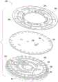
图1A是根据实施例的转子的说明性俯视图。图1B是图1A中描绘的转子的说明性仰视图。FIG. 1A is an illustrative top view of a rotor according to an embodiment. FIG. 1B is an illustrative bottom view of the rotor depicted in FIG. 1A .
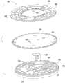
图2A是根据其他实施例的转子组件的说明性分解图。图2B是图2A中描绘的转子组件的说明性分解图。图2C是图2A中描绘的转子组件的说明性组装透视图。2A is an illustrative exploded view of a rotor assembly according to other embodiments. Figure 2B is an illustrative exploded view of the rotor assembly depicted in Figure 2A. Figure 2C is an illustrative assembled perspective view of the rotor assembly depicted in Figure 2A.
图3A是根据其他实施例的转子的截面侧视图。图3B是图3A中描绘的转子的孔的详细截面侧视图。3A is a cross-sectional side view of a rotor according to other embodiments. Figure 3B is a detailed cross-sectional side view of the bore of the rotor depicted in Figure 3A.
图4A是根据实施例的转子的一组孔和一组反射器的详细俯视图。图4B是根据实施例的转子的入口和通道的详细俯视图。图4C是图4A中描绘的反射器的截面侧视图。4A is a detailed top view of a set of holes and a set of reflectors of a rotor according to an embodiment. 4B is a detailed top view of the inlets and channels of the rotor, according to an embodiment. Figure 4C is a cross-sectional side view of the reflector depicted in Figure 4A.
图5A是根据实施例的转子的弧形腔的详细俯视图。图5B是图5A中描绘的弧形腔的详细截面侧视图。5A is a detailed top view of an arcuate cavity of a rotor according to an embodiment. Figure 5B is a detailed cross-sectional side view of the arcuate cavity depicted in Figure 5A.
图6是根据实施例的转子的通道的详细俯视图。Fig. 6 is a detailed top view of the channels of the rotor according to the embodiment.
图7A是根据其他实施例的转子组件的说明性分解图。图7B是图7A中描绘的转子组件的层的详细透视图。7A is an illustrative exploded view of a rotor assembly according to other embodiments. Figure 7B is a detailed perspective view of the layers of the rotor assembly depicted in Figure 7A.
图8A是根据其他实施例的流体分析系统的框图。图8B是图8A中描绘的流体分析系统的控制系统的框图。8A is a block diagram of a fluid analysis system according to other embodiments. 8B is a block diagram of a control system of the fluid analysis system depicted in FIG. 8A.
图9是根据实施例的使用转子的方法的说明性流程图。9 is an illustrative flowchart of a method of using a rotor, under an embodiment.
图10A是根据实施例的制造转子的方法的说明性流程图。图10B是多射注射成型转子的方法的说明性流程图。FIG. 10A is an illustrative flowchart of a method of manufacturing a rotor, according to an embodiment. 10B is an illustrative flowchart of a method of multi-shot injection molding a rotor.
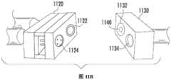
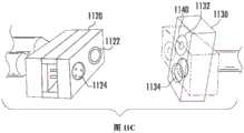
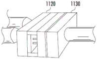
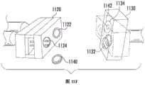
图11A-图11F是图10B的方法中描绘的步骤的说明性透视图。图11A描绘闭模和注模过程,图11B描绘开模过程,图11C描绘模具旋转过程,图11D描绘闭模和注模过程,图11E描绘开模过程,且图11F描绘模具旋转和转子弹射过程。11A-11F are illustrative perspective views of steps depicted in the method of FIG. 10B. 11A depicts the mold closing and injection process, FIG. 11B depicts the mold opening process, FIG. 11C depicts the mold rotation process, FIG. 11D depicts the mold closing and injection process, FIG. 11E depicts the mold opening process, and FIG. 11F depicts the mold rotation and rotor ejection process.
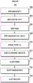
图12是根据实施例的检查转子的方法的说明性流程图。FIG. 12 is an illustrative flowchart of a method of inspecting a rotor, according to an embodiment.
图13A是根据实施例的转子的说明性图像。图13B是图13A中描绘的转子的高对比图像。13A is an illustrative image of a rotor, according to an embodiment. Figure 13B is a high contrast image of the rotor depicted in Figure 13A.
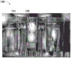
图14A是根据实施例的转子的孔中的试剂的说明性侧视图图像。图14B是根据实施例的转子的孔中的试剂的说明性俯视图图像。14A is an illustrative side view image of reagents in wells of a rotor, according to an embodiment. 14B is an illustrative top view image of reagents in wells of a rotor, according to an embodiment.
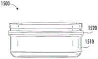
图15A是根据实施例的容器的说明性侧视图。图15B是图15A中描绘的容器的说明性截面图。图15C是图15A中描绘的容器的分解图。图15D是包括图15A中描绘的容器的转子组件的透视图。图15E是图15D中描绘的转子组件的分解图。15A is an illustrative side view of a container, according to an embodiment. Figure 15B is an illustrative cross-sectional view of the container depicted in Figure 15A. Figure 15C is an exploded view of the container depicted in Figure 15A. Figure 15D is a perspective view of a rotor assembly including the container depicted in Figure 15A. Figure 15E is an exploded view of the rotor assembly depicted in Figure 15D.
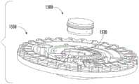
图16是根据实施例的焊缝巢的说明性透视图。16 is an illustrative perspective view of a weld nest, according to an embodiment.
图17是根据实施例的光掩模壳体的说明性分解透视图。17 is an illustrative exploded perspective view of a photomask housing according to an embodiment.
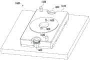
图18是根据实施例的转子制造系统的说明性透视图。Fig. 18 is an explanatory perspective view of a rotor manufacturing system according to the embodiment.
具体实施方式Detailed ways
本文描述了转子设备、系统及其使用方法的实施例。这些系统和方法可以用于表征和/或定量生物样本,并允许评估受试者健康和/或诊断病症。例如,本文描述的转子可以被配置用于光学分析生物流体,且具体地说,用于在使用转子将血浆从细胞材料中分离之后分析血浆。更具体地,转子可以被配置为将血浆从全血中分离,且/或根据需要添加稀释流体以稀释样本,并且将其分配到被配置用于光学分析其内容物的单独的孔(例如,比色皿)中。每个孔可包含一种或多种可有助于对孔中样本进行生化分析的物质。样本可以与一个或多个孔中的一种或多种试剂结合。在暴露于可以被检测到和分析的光束时,样本与试剂之间的生化反应可能会产生光学效应。例如,通过在转子旋转时用样本填充一组孔同时光学分析每个孔中的流体,样本可能会发生反应或其他变化,从而导致颜色、荧光、发光、其组合等中的一个或多个发生变化,该变化可以通过分光光度计、荧光计、光检测器、其组合等中的一个或多个来测量。Embodiments of rotor devices, systems, and methods of using the same are described herein. These systems and methods can be used to characterize and/or quantify biological samples and allow for assessment of subject health and/or diagnosis of disorders. For example, the rotors described herein may be configured for optical analysis of biological fluids, and in particular, for analyzing plasma after separation of the plasma from cellular material using the rotor. More specifically, the rotor can be configured to separate plasma from whole blood and/or add dilution fluid as needed to dilute the sample and distribute it to individual wells configured for optical analysis of their contents (e.g., cuvette). Each well may contain one or more substances that may facilitate biochemical analysis of the sample in the well. A sample can be bound to one or more reagents in one or more wells. Biochemical reactions between samples and reagents may produce optical effects when exposed to light beams that can be detected and analyzed. For example, by filling a set of wells with sample while optically analyzing the fluid in each well as the rotor rotates, the sample may undergo a reaction or other change resulting in one or more of color, fluorescence, luminescence, combinations thereof, etc. The change can be measured by one or more of a spectrophotometer, a fluorometer, a photodetector, combinations thereof, and the like.
本文详细描述的每个转子(100、200、300、400、500、600、700)可以接收样本,该样本包括但不限于全血,其可包含血液、血清、血浆、尿液、痰、精液、唾液、晶状体流体、脑液、脊髓液、羊水和组织培养基中的一种或多种;以及食品和工业化学品及其组合等。本文所述的任何转子(100、200、300、400、500、600、700)可以与合适的流体分析系统(例如,光学分析仪)一起使用。Each rotor (100, 200, 300, 400, 500, 600, 700) described in detail herein can receive a sample including, but not limited to, whole blood, which can contain blood, serum, plasma, urine, sputum, semen , saliva, lens fluid, cerebrospinal fluid, amniotic fluid, and tissue culture media; and food and industrial chemicals and combinations thereof, among others. Any of the rotors (100, 200, 300, 400, 500, 600, 700) described herein may be used with a suitable fluid analysis system (eg, an optical analyzer).
本文所公开的设备可以适用于执行各种各样的分析程序和测定。分析程序可能需要将样本与一种或多种试剂结合,使得发生某种可能与一种或多种试剂有关的可检测的变化,从而使得发生某种可能与样本的特定组分(分析物)的存在和/或数量或样本特性有关的可检测的变化。例如,样本可能会发生反应或其他变化,从而导致颜色、荧光、发光等发生变化,该变化可以通过分光光度计、荧光计、光检测器等来测量。在一些情况下,此类测定程序可能是同质的且不需要分离步骤。在其他情况下,在发生免疫反应后,测定程序可以将样本(例如血浆)与腔或孔分离。取决于将要分析的特定样本和将要检测的组分,任何数量的分析方法都可以适用于本文所公开的离心转子设备。The devices disclosed herein can be adapted to perform a wide variety of analytical procedures and assays. Analytical procedures may entail binding a sample to one or more reagents such that a detectable change occurs that may be associated with one or more reagents, resulting in a detectable changes related to the presence and/or amount or characteristics of the sample. For example, a sample may undergo a reaction or other change resulting in a change in color, fluorescence, luminescence, etc., which may be measured by a spectrophotometer, fluorometer, light detector, or the like. In some cases, such assay procedures may be homogenous and require no separation steps. In other cases, the assay procedure may separate the sample (eg, plasma) from the cavity or well after the immune response has occurred. Depending on the particular sample to be analyzed and the components to be detected, any number of analytical methods may be suitable for use with the centrifuge rotor devices disclosed herein.
在一些实施例中,转子设备、试剂、系统和方法可以包括描述于以下各者中的设备、系统、组件、元件、组成和步骤中的一个或多个:1990年6月4日提交的标题为“用于从生物流体中分离细胞的装置和方法(APPARATUS AND METHOD FOR SEPARATING CELLS FROMBIOLOGICAL FLUIDS)”的美国专利申请序列号07/532,524,和/或1991年4月1日提交的标题为“用于光学分析生物流体的装置和方法(APPARATUS AND METHOD FOR OPTICALLYANALYZING BIOLOGICAL FLUIDS)”的美国专利申请序列号07/678,824,和/或1991年4月1日提交的标题为“具有流分隔件的离心转子(CENTRIFUGAL ROTOR HAVING FLOW PARTITION)”的美国专利申请序列号07/678,823,和/或1991年8月19日提交的标题为“用于分析测试的试剂组成(REAGENT COMPOSITIONS FOR ANALYTICAL TESTING)”的美国专利申请序列号07/747,179,和/或1992年2月11日提交的标题为“用于分析转子的试剂容器(REAGENTCONTAINER FOR ANALYTICAL ROTOR)”的美国专利申请序列号07/833,689,和/或1991年10月29日提交的标题为“用于具有过流腔室的分析转子的样本计量端口(SAMPLE METERINGPORT FOR ANALYTICAL ROTOR HAVING OVERFLOW CHAMBER)”的美国专利申请序列号07/783,041,和/或1992年4月24日提交的标题为“低温装置(CRYOGENIC APPARATUS)”的美国专利申请序列号07/873,327,和/或1993年9月1日提交的标题为“通过分离比色皿的方式同时进行比色皿填充(SIMULTANEOUS CUVETTES FILLING WITH MEANS TO ISOLATE CUVETTES)”的美国专利申请序列号08/115,163,和/或1993年9月20日提交的标题为“具有染料混合室的分析转子(ANALYTICAL ROTOR WITH DYE MIXING CHAMBER)”的美国专利申请序列号08/124,525,和/或1995年12月26日提交的标题为“光度分析的方法(METHODS FORPHOTOMETRIC ANALYSIS)”的美国专利申请序列号08/292,558,和/或1994年12月6日提交的标题为“用于超声波焊接的方法和设备(METHOD AND DEVICE FOR ULTRASONIC WELDING)”的美国专利申请序列号08/350,856,和/或2004年5月5日提交的标题为“用于提高计量精度的改良虹吸管(MODIFIED SIPHONS FOR IMPROVING METERING PRECISION)”的美国专利申请序列号10/840,763,和/或2017年6月27日提交的标题为“具有改良导管的设备(DEVICESWITH MODIFIED CONDUITS)”的国际专利申请序列号PCTUS2017/039460,上述文献中的每一个的全部内容通过引用方式并入本文中。In some embodiments, the rotor devices, reagents, systems and methods may include one or more of the devices, systems, assemblies, elements, compositions and steps described in: Title of filed June 4, 1990 U.S. Patent Application Serial No. 07/532,524 for "APPARATUS AND METHOD FOR SEPARATING CELLS FROMBIOLOGICAL FLUIDS," and/or filed April 1, 1991, entitled "Using U.S. Patent Application Serial No. 07/678,824 for APPARATUS AND METHOD FOR OPTICALLYANALYZING BIOLOGICAL FLUIDS," and/or the title "Centrifugal Rotor with Flow Partitions" filed April 1, 1991 (CENTRIFUGAL ROTOR HAVING FLOW PARTITION)," and/or U.S. Patent Application Serial No. 07/678,823, filed August 19, 1991, entitled "REAGENT COMPOSITIONS FOR ANALYTICAL TESTING" Application Serial No. 07/747,179, and/or U.S. Patent Application Serial No. 07/833,689, filed February 11, 1992, entitled "REAGENT CONTAINER FOR ANALYTICAL ROTOR," and/or 1991 U.S. Patent Application Serial No. 07/783,041, entitled "SAMPLE METERINGPORT FOR ANALYTICAL ROTOR HAVING OVERFLOW CHAMBER," filed October 29, and/or April 1992 U.S. Patent Application Serial No. 07/873,327, filed September 24, entitled "CRYOGENIC APPARATUS," and/or filed September 1, 1993, entitled "Simultaneous Colorimetric US Patent Application Serial No. 08/115,163, "SIMULTANEOUS CUVETTES FILLING WITH MEANS TO ISOLATE CUVETTES", and/or filed September 20, 1993, entitled "ANALYTICAL ROTOR WITH DYE MIXING CHAMBER), and/or U.S. Patent Application Serial No. 08/292,558, filed December 26, 1995, entitled "METHODS FORPHOTOMETRIC ANALYSIS," and/or U.S. Patent Application Serial No. 08/350,856, entitled "METHOD AND DEVICE FOR ULTRASONIC WELDING," filed December 6, 1994, and/or titled May 5, 2004 U.S. Patent Application Serial No. 10/840,763 for "MODIFIED SIPHONS FOR IMPROVING METERING PRECISION," and/or filed June 27, 2017, entitled "DEVICESWITH MODIFIED CONDUITS)", the entire contents of each of which are incorporated herein by reference.
I.设备I. Equipment
本文描述了可以在所描述的各种系统的一些实施例中使用的设备。如本文所述的转子可以包括一组腔和孔。在一些实施例中,可以将一种或多种物质(例如,试剂、冻干试剂)置于转子的一个或多个孔中,以促进样本分析。例如,试剂可以以干燥的形式提供,使其可以在运输和储存过程中保持稳定和完整。在一些实施例中,转子可以限定开口、通道、腔、导管、孔和/或其他结构,其被配置为提供一种或多种从生物样本(例如全血)中分离的细胞组分,从而测量预定体积的液体样本(例如血浆),将样本与预定稀释剂混合,并且将稀释的样本输送到一组孔中进行光学分析。输送到一组孔中的流体可以在一组孔内发生一个或多个反应,这可以有助于表征和量化流体中的一种或多种分析物。样本可以在发生或未发生先前反应的情况下在存在于转子中时进行光学分析。Devices are described herein that may be used in some embodiments of the various systems described. A rotor as described herein may include a set of cavities and bores. In some embodiments, one or more substances (eg, reagents, lyophilized reagents) can be placed in one or more wells of the rotor to facilitate sample analysis. For example, reagents can be provided in a dry form so that they remain stable and intact during shipping and storage. In some embodiments, a rotor may define openings, channels, lumens, conduits, holes, and/or other structures configured to provide one or more cellular components isolated from a biological sample (e.g., whole blood) to thereby A predetermined volume of a liquid sample (eg, plasma) is measured, the sample is mixed with a predetermined diluent, and the diluted sample is delivered to a set of wells for optical analysis. Fluid delivered to a set of wells can undergo one or more reactions within the set of wells, which can aid in the characterization and quantification of one or more analytes in the fluid. Samples can be analyzed optically while present in the rotor with or without previous reactions.
装置可以被配置为与流体分析系统一起使用以量化和分析样本的特性。例如,可以在转子旋转时对每个孔进行光学测量(例如吸光度)。预定波长的光束可以被引导通过一组孔。此光可以被试剂与流体样本组分之间的反应产物部分吸收。光被吸收的程度可以取决于流体样本中反应产物的浓度。通过将透过孔的光的强度与参考强度进行比较,可以计算出流体和试剂之间给定反应产物的浓度。反应产物的浓度可用于计算样本流体中相应组分的浓度。The device can be configured for use with a fluid analysis system to quantify and analyze characteristics of a sample. For example, optical measurements (such as absorbance) can be taken for each well as the rotor rotates. A light beam of predetermined wavelength may be directed through a set of holes. This light may be partially absorbed by reaction products between reagents and fluid sample components. The degree to which light is absorbed may depend on the concentration of reaction products in the fluid sample. By comparing the intensity of light transmitted through the aperture to a reference intensity, the concentration of a given reaction product between fluid and reagent can be calculated. The concentration of the reaction product can be used to calculate the concentration of the corresponding component in the sample fluid.
转子rotor
在一些实施例中,转子可以包括一个或多个被配置为辅助样本分析的部件。具体来说,转子可以包括一个或多个基本透明的层以及另一个基本上吸收红外辐射的层(例如,不透明层)。例如,不透明层可以由炭黑和可以是黑色的丙烯酸化合物组成。与透明转子不同,通过这种组合形成的不透明性可以提供与放置在转子中的生物样本一致的对比背景。这可以帮助用户(例如,操作员、技术人员)在转子中施加和验证样本,以及检查不同层的转子焊缝。此外,可以使用激光焊接技术将转子层耦合在一起,这可以减少制造周期时间并提高转子质量。例如,激光焊接可以增加焊接一致性并改善转子形状(例如,转子的平坦度)。In some embodiments, a rotor may include one or more components configured to assist in sample analysis. In particular, the rotor may include one or more substantially transparent layers and another layer that substantially absorbs infrared radiation (eg, an opaque layer). For example, the opaque layer may consist of carbon black and an acrylic compound which may be black. Unlike transparent rotors, the opacity created by this combination provides a consistent contrasting background for biological samples placed in the rotor. This can help users (eg, operators, technicians) apply and verify samples in the rotor, as well as inspect rotor welds in different layers. Additionally, the rotor layers can be coupled together using laser welding techniques, which can reduce manufacturing cycle times and improve rotor quality. For example, laser welding can increase weld consistency and improve rotor shape (eg, rotor flatness).
图1A是转子(100)的说明性俯视图,而图1B是转子(100)的说明性仰视图。转子(100)可以包括基本透明的第一层(101),其中第二层(102)的第一侧(例如,下侧)耦合到第一层(101)。第一层(101)和第二层(102)可以共同限定一组孔(130)。例如,可以通过第一层(101)形成一组孔(130)中的每个孔的至少一个基部(例如,底部)。与一组孔(130)的基部相对的每个孔的开口(例如顶部)可以由第二层(102)限定。一组孔(130)中的每个孔的侧壁可以是大体上圆柱形的,并且可以由第一层(101)、第二层(102)或其某种组合形成。在一些实施例中,一组孔(130)中的每个孔可具有约1.0mm与约10mm之间的深度,以及约5mm或更小的直径。在一些实施例中,转子(100)可以包括5个与50个之间的孔。在一些实施例中,一组孔(130)中的每个孔可限定约1μL与约40μL之间的体积。在一些实施例中,一组孔(130)中的相邻孔可以间隔开约1mm至约30mm。相对于图3A-图3B更详细地描述了转子的一组孔。在图1A中,示出第二层(102)设置在第一层(101)上方。FIG. 1A is an illustrative top view of the rotor (100), and FIG. IB is an illustrative bottom view of the rotor (100). The rotor (100) may include a substantially transparent first layer (101), wherein a first side (eg, lower side) of a second layer (102) is coupled to the first layer (101). The first layer (101) and the second layer (102) may collectively define a set of apertures (130). For example, at least one base (eg, bottom) of each well in the set of wells (130) may be formed by the first layer (101). An opening (eg, a top) of each well opposite a base of a set of wells (130) may be defined by the second layer (102). The sidewall of each hole in the set of holes (130) may be generally cylindrical and may be formed from the first layer (101), the second layer (102), or some combination thereof. In some embodiments, each hole in set of holes (130) may have a depth of between about 1.0 mm and about 10 mm, and a diameter of about 5 mm or less. In some embodiments, the rotor (100) may include between 5 and 50 holes. In some embodiments, each well in set of wells (130) can define a volume of between about 1 μL and about 40 μL. In some embodiments, adjacent holes in a set of holes (130) may be spaced apart by about 1 mm to about 30 mm. The set of holes of the rotor is described in more detail with respect to FIGS. 3A-3B . In Fig. 1A, the second layer (102) is shown disposed above the first layer (101).
在一些实施例中,第二层(102)的至少一部分可以基本上吸收红外辐射。例如,第二层(102)可以是不透明的(例如,黑色),为清楚起见在图中未示出。同样,为了清楚起见,未描绘本文所述的转子的任何透明部分的透明度。在一些实施例中,第二层(102)的至少一部分可以基本上吸收中红外辐射和近红外辐射中的至少一个。红外辐射的波长可以在约700nm与约1mm之间。中红外辐射的波长可以在约3μm与约8μm之间。近红外辐射的波长可以在约0.75μm与约1.4μm之间。可见光的波长可以在约400nm与约700nm之间。紫外光的波长可以在约10nm与约400nm之间。在一些实施例中,第二层(102)的至少一部分可以基本上吸收至少940nm波长的辐射。In some embodiments, at least a portion of the second layer (102) can substantially absorb infrared radiation. For example, the second layer (102) may be opaque (eg, black), not shown in the figure for clarity. Also, for clarity, the transparency of any transparent portion of the rotors described herein is not depicted. In some embodiments, at least a portion of the second layer (102) can substantially absorb at least one of mid-infrared radiation and near-infrared radiation. The infrared radiation may have a wavelength between about 700 nm and about 1 mm. The wavelength of mid-infrared radiation may be between about 3 μm and about 8 μm. The near infrared radiation may have a wavelength between about 0.75 μm and about 1.4 μm. The wavelength of visible light may be between about 400 nm and about 700 nm. The wavelength of the ultraviolet light may be between about 10 nm and about 400 nm. In some embodiments, at least a portion of the second layer (102) can substantially absorb radiation at a wavelength of at least 940 nm.
如本文所用,术语“透明”、“透明度”及其变体可以理解为在预定波长和/或化学重要性(例如对于激光焊接)为约10%或更大的波长范围内透过其层的光透射,而术语“不透明”、“不透明度”、“不透明性”及其变体可以包括在预定波长和/或约10%或更小的波长范围内透过其层的光透射。例如,丙烯酸通常可以认为是透明的,因为其提供约90%的UV波长透射。使用激光焊接形成的透明塑料可以保持其波长透明度。此外,材料的不透明性可以对应于在预定波长和/或预定波长范围下的能量吸收。如本文所用,基本上吸收红外辐射的材料对应于可以吸收(预定波长和功率范围的)红外辐射以在预定时间段内将材料从固态相转变为熔融相的材料。As used herein, the terms "transparent", "transparency" and variants thereof are understood to mean transparency of its layer within a wavelength range of predetermined wavelength and/or chemical importance (e.g. for laser welding) of about 10% or greater Light transmission, while the terms "opaque," "opacity," "opaqueness," and variations thereof may include light transmission through a layer thereof at a predetermined wavelength and/or within about 10% or less of a wavelength range. For example, acrylic can generally be considered transparent because it provides about 90% transmission of UV wavelengths. Transparent plastics formed using laser welding maintain their wavelength transparency. Furthermore, the opacity of the material may correspond to energy absorption at a predetermined wavelength and/or predetermined wavelength range. As used herein, a material that substantially absorbs infrared radiation corresponds to a material that can absorb infrared radiation (of a predetermined wavelength and power range) to transform the material from a solid phase to a molten phase within a predetermined period of time.
第一层(101)和第二层(102)可以进一步共同限定转子(100)的其他结构(例如,腔、通道、孔、突起、突出部),如本文中更详细地描述。例如,第二层(134)可以限定一组弧形腔(110、112、114)、一组通道(120、122)、一组入口(132、134)和一组反射器(140)的一个或多个部分。在一些实施例中,一组通道(120、122)可以在弧形腔(110)与一组孔(130、150、152)之间建立流体连通路径。The first layer (101) and second layer (102) may further collectively define other structures (eg, cavities, channels, holes, protrusions, protrusions) of the rotor (100), as described in more detail herein. For example, the second layer (134) may define one of a set of curved cavities (110, 112, 114), a set of channels (120, 122), a set of inlets (132, 134), and a set of reflectors (140). or multiple sections. In some embodiments, a set of channels (120, 122) may establish a fluid communication path between the arcuate cavity (110) and the set of holes (130, 150, 152).
一组孔(130)中的每个孔可以通过相应的入口(132、134)耦合到通道(120)。一组孔(130)中的每个孔可以被配置为串联填充。也就是说,转子(100)可以包括一组高密度、串联填充的比色皿。在一些实施例中,一组入口中的每个入口可以具有相同尺寸。在其他实施例中,一组入口中的每个入口可以具有不同尺寸。例如,第一组入口(132)的宽度可以小于第二组入口(134)的宽度。不同的入口尺寸可以允许每个孔(130)以不同的旋转转子(100)的速度(即,由于加速度)填充流体。第二组入口(134)的较宽的宽度可以被配置为以相对较低的每分钟转数(例如,低于约4,000RPM)容纳一个方向上的液体和相反方向上的气体的双向流动,如本文更详细地描述。在一些实施例中,一组入口的宽度可以在约0.25mm与约3.0mm之间,一组入口的长度可以在约0.5mm与约6.0mm之间,并且一组入口的深度可以在约0.1mm与约0.25mm之间。Each aperture in set of apertures (130) may be coupled to channel (120) through a respective inlet (132, 134). Each well in a set of wells (130) may be configured to fill in series. That is, the rotor (100) may comprise a set of high-density, series-packed cuvettes. In some embodiments, each inlet in a set of inlets may be of the same size. In other embodiments, each inlet in a set of inlets may be of a different size. For example, the width of the first set of inlets (132) may be smaller than the width of the second set of inlets (134). Different inlet sizes may allow each hole (130) to fill with fluid at different speeds (ie, due to acceleration) of rotating the rotor (100). The wider width of the second set of inlets (134) may be configured to accommodate bi-directional flow of liquid in one direction and gas in the opposite direction at relatively low revolutions per minute (e.g., less than about 4,000 RPM), As described in more detail herein. In some embodiments, a set of inlets may have a width between about 0.25 mm and about 3.0 mm, a set of inlets may have a length between about 0.5 mm and about 6.0 mm, and a set of inlets may have a depth of about 0.1 mm. mm and about 0.25mm.
在一些实施例中,弧形腔(112、114)可以对应于相应的计量室和混合室。例如,在打开稀释剂杯之后,可以接收稀释剂流体并将其容纳在计量室(112)中。混合室(114)可以被配置为耦合到计量室(112)和弧形腔(110),使得来自那些腔中的每一个的流体可以在混合室(114)内合并(例如,样本和稀释剂)。在一些实施例中,一组孔可以包括样本检查孔(150)和红细胞(RBC)孔(152)。样本检查孔(150)可以用作是否已经将足够的样本输入到转子(100)中的度量。例如,未填充或未完全填充的样本检查孔(150)可以指示已将不足的样本插入到转子(100)中以执行流体分析。RBC孔(152)可以被配置为接收和容纳样本的红细胞。例如,可以将全血样本分离成容纳在RBC孔(152)中的红细胞和可以填充一组孔(130)的血浆。In some embodiments, arcuate cavities (112, 114) may correspond to respective metering and mixing chambers. For example, after the diluent cup is opened, diluent fluid may be received and contained in the metering chamber (112). Mixing chamber (114) can be configured to couple to metering chamber (112) and arcuate chamber (110) such that fluids from each of those chambers can combine within mixing chamber (114) (e.g., sample and diluent ). In some embodiments, a set of wells may include sample inspection wells (150) and red blood cell (RBC) wells (152). The sample inspection hole (150) can be used as a measure of whether enough sample has been input into the rotor (100). For example, an underfilled or incompletely filled sample access hole (150) may indicate that insufficient sample has been inserted into rotor (100) to perform fluid analysis. RBC well (152) may be configured to receive and contain red blood cells of a sample. For example, a whole blood sample can be separated into red blood cells housed in RBC wells (152) and plasma which can fill a set of wells (130).
在一些实施例中,第一层(101)可以对紫外光、可见光和红外辐射中的一个或多个基本透明。在一些实施例中,第一层(101)和第二层(102)可以独立地由丙烯酸、聚碳酸酯、环烯烃共聚物(COC)、聚苯乙烯、丙烯腈丁二烯苯乙烯(ABS)和其他对紫外光透明的材料中的一种或多种组成。In some embodiments, the first layer (101) can be substantially transparent to one or more of ultraviolet light, visible light, and infrared radiation. In some embodiments, the first layer (101) and the second layer (102) can be independently made of acrylic, polycarbonate, cycloolefin copolymer (COC), polystyrene, acrylonitrile butadiene styrene (ABS ) and one or more of other UV-transparent materials.
在一些实施例中,第二层(102)可以包括按重量计至少约0.1%的有机和无机颜料中的至少一种。例如,第二层(102)可以包括按重量计在约0.2%至约0.4%之间的炭黑。In some embodiments, the second layer (102) can include at least about 0.1% by weight of at least one of organic and inorganic pigments. For example, the second layer (102) may include between about 0.2% and about 0.4% by weight carbon black.
有机颜料可以包括炭黑和激光吸收组分。炭黑的吸收范围可以在约500nm与约2200nm之间。基于浓度(例如,在940nm下按重量计约0.1%或更多),炭黑可以具有在约10μm与约100μm之间的近红外辐射波长的光穿透深度。在一些实施例中,激光吸收组分可以基本上吸收在约700nm至约8μm之间的辐射。例如,

无机颜料可以包括磷酸铜和氧化铟锡(ITO)。磷酸铜的吸收范围可以在约900nm与约1600nm之间。ITO的吸收范围可以大于约1000nm。Inorganic pigments may include copper phosphate and indium tin oxide (ITO). The absorption range of copper phosphate may be between about 900 nm and about 1600 nm. The absorption range of ITO can be greater than about 1000 nm.
如本文所述的转子设备可以包括被配置为安装在诸如离心机的系统上以进行旋转的开口(例如,容器)。离心机可以包括例如其上可以安装转子的垂直驱动轴。然而,由于转子设计和转子内的流体流动中的一种或多种,转子可能具有固有不平衡或残差不平衡。例如,生物样本可以被配置为在整个离心过程中流过转子的不同腔、腔室和通道。在一些情况下,转子可以被配置为在流体充满一组孔时通常是平衡的,但是当输入样本并将其保持在保持室(例如,弧形腔)中时,转子可能是不平衡的。因此,转子可能在整个离心过程中产生不期望的噪音,这可能降低在即时检验设置中转子使用的期望。A rotor device as described herein may include an opening (eg, container) configured to be mounted for rotation on a system such as a centrifuge. A centrifuge may include, for example, a vertical drive shaft on which a rotor may be mounted. However, due to one or more of rotor design and fluid flow within the rotor, the rotor may have an inherent unbalance or residual unbalance. For example, biological samples can be configured to flow through the different cavities, chambers, and channels of the rotor throughout the centrifugation process. In some cases, the rotor may be configured to be generally balanced when fluid fills a set of wells, but may be unbalanced when a sample is input and retained in a holding chamber (eg, an arcuate chamber). Consequently, the rotor may generate undesired noise throughout the centrifugation process, which may reduce the expectation of rotor use in a point-of-care setting.
如图1B所示,第二层(102)的第一侧(例如,下侧、底侧)可以包括一组弧形突起(160)和孔(180)。一组弧形突起(160)可以具有预定形状、数量、位置和质量分布,该预定形状、数量、位置和质量分布被配置为使转子(100)的质心与转子(100)的中心偏移。另外或替代地,第二层(102)可以包括具有预定形状、数量、位置和体积的一组凹陷部分(162)。例如,一组凹陷部分(162)和弧形突起(160)可以具有弧形、径向、椭圆形、正割和线性形状中的一个或多个。在一些实施例中,一组凹陷部分(162)可以是平行且弧形的。在一些实施例中,转子的质心可以被配置为在距转子的中心至多约0.5mm之间。以这种方式,在整个离心过程中,转子的质心可以更靠近具有流体流动的转子的质心。这可以帮助降低转子(100)的离心过程中的总体噪音,特别是在不同的离心速度下。As shown in FIG. 1B, the first side (eg, lower side, bottom side) of the second layer (102) may include a set of arcuate protrusions (160) and holes (180). A set of arcuate protrusions (160) may have a predetermined shape, number, location and mass distribution configured to offset the center of mass of the rotor (100) from the center of the rotor (100). Additionally or alternatively, the second layer (102) may include a set of recessed portions (162) having a predetermined shape, number, location and volume. For example, a set of recessed portions (162) and arcuate protrusions (160) may have one or more of arcuate, radial, elliptical, secant, and linear shapes. In some embodiments, the set of recessed portions (162) may be parallel and arcuate. In some embodiments, the center of mass of the rotor may be configured to be at most about 0.5 mm from the center of the rotor. In this way, the center of mass of the rotor can be brought closer to the center of mass of the rotor with fluid flow throughout the centrifugation process. This can help reduce the overall noise during centrifugation of the rotor (100), especially at different centrifugation speeds.
在一些实施例中,第一层(101)和/或第二层(102)可以使用如本文中更详细描述的注射成型(例如,多射成型)和/或机加工形成。在一些实施例中,可以使用超声焊接、激光焊接、粘合剂(例如,胶带)和/或溶剂粘合中的一种或多种将第一层(101)和/或第二层(102)粘合到转子(100)的其他层。In some embodiments, the first layer (101) and/or the second layer (102) may be formed using injection molding (eg, multi-shot molding) and/or machining as described in more detail herein. In some embodiments, the first layer (101) and/or the second layer (102) may be bonded using one or more of ultrasonic welding, laser welding, adhesive (e.g., tape), and/or solvent bonding. ) bonded to other layers of the rotor (100).
例如,激光焊接可以使用半导体二极管激光器、固态Nd:YAG激光器和光纤激光器中的一种或多种。二极管激光器可以产生波长在约800nm与约2000nm之间(例如,约940nm、约980nm)的光束。Nd:YAG激光器可以产生波长约1064nm的光束。光纤激光器可以产生波长在约1030nm与约1620nm之间的光束。For example, laser welding may use one or more of semiconductor diode lasers, solid state Nd:YAG lasers, and fiber lasers. Diode lasers can generate light beams having wavelengths between about 800 nm and about 2000 nm (eg, about 940 nm, about 980 nm). Nd:YAG lasers can produce beams with a wavelength of about 1064nm. Fiber lasers can produce light beams with wavelengths between about 1030 nm and about 1620 nm.
在一些实施例中,转子(100)的直径可以在约40mm与约120mm之间,并且厚度可以在约10mm与约30mm之间,包括其间的所有值和子范围。In some embodiments, the diameter of the rotor (100) may be between about 40 mm and about 120 mm, and the thickness may be between about 10 mm and about 30 mm, including all values and subranges therebetween.
图2A和图2B是根据其他实施例的转子组件(200)的说明性分解图。转子组件(200)可以包括在结构和/或功能上类似于本文所述的转子(100、300、400、500、600、700)的转子。例如,转子组件(200)可以包括基本透明的第一层(201),所述第一层耦合到第二层(202)的第一侧(例如,下侧)。第一层(201)和第二层(202)可以共同限定一组孔(230)。在一些实施例中,第二层(202)的至少一部分可以基本上吸收红外辐射。在一些实施例中,第二层(202)的至少一部分可以基本上吸收中红外辐射和近红外辐射中的一个或多个。例如,第二层(202)的至少一部分可以基本上吸收至少940nm波长的辐射。第一层(201)和第二层(202)可以进一步共同限定转子(200)的其他结构(例如,腔、通道、孔、突起、突出部),如本文中更详细地描述。例如,第二层(102)可以限定弧形腔(210)和一组通道(220)的一个或多个部分。在一些实施例中,一组通道(220)可以在弧形腔(210)与一组孔(230)之间建立流体连通路径。2A and 2B are illustrative exploded views of a rotor assembly (200) according to other embodiments. The rotor assembly (200) may include a rotor similar in structure and/or function to the rotors (100, 300, 400, 500, 600, 700) described herein. For example, the rotor assembly (200) may include a substantially transparent first layer (201) coupled to a first side (eg, lower side) of a second layer (202). The first layer (201) and the second layer (202) may collectively define a set of apertures (230). In some embodiments, at least a portion of the second layer (202) can substantially absorb infrared radiation. In some embodiments, at least a portion of the second layer (202) can substantially absorb one or more of mid-infrared radiation and near-infrared radiation. For example, at least a portion of the second layer (202) can substantially absorb radiation at a wavelength of at least 940 nm. First layer (201) and second layer (202) may further collectively define other structures (eg, cavities, channels, holes, protrusions, projections) of rotor (200), as described in more detail herein. For example, second layer (102) may define one or more portions of arcuate cavity (210) and set of channels (220). In some embodiments, a set of channels (220) may establish a fluid communication path between the arcuate cavity (210) and the set of holes (230).
在一些实施例中,第二层(202)可以包括按重量计至少约0.1%的炭黑。例如,第二层(202)可以包括按重量计在约0.2%至约0.4%之间的炭黑。在一些实施例中,第一层(201)和/或第二层(202)可以使用如本文中更详细描述的注射成型(例如,多射成型)和/或机加工形成。在一些实施例中,可以使用超声焊接、激光焊接、粘合剂(例如,胶带)和/或溶剂粘合中的一种或多种将第一层(201)和/或第二层(202)粘合到转子(200)的其他层。例如,激光焊接可以使用半导体二极管激光器、固态Nd:YAG激光器和光纤激光器中的一种或多种。In some embodiments, the second layer (202) can include at least about 0.1% by weight carbon black. For example, the second layer (202) may include between about 0.2% and about 0.4% by weight carbon black. In some embodiments, the first layer (201) and/or the second layer (202) may be formed using injection molding (eg, multi-shot molding) and/or machining as described in more detail herein. In some embodiments, the first layer (201) and/or the second layer (202) may be bonded using one or more of ultrasonic welding, laser welding, adhesive (e.g., tape), and/or solvent bonding. ) bonded to other layers of the rotor (200). For example, laser welding may use one or more of semiconductor diode lasers, solid state Nd:YAG lasers, and fiber lasers.
转子组件(200)可以包括第三层(203),所述第三层可以耦合到第二层(202)的第二侧(例如,顶侧)。第三层(203)可以限定被配置为接收流体(例如血液)的开口(240)。第三层(203)可以是基本透明的。通道(220)可以在开口(240)与一组孔(230)之间建立流体连通路径。第三层(203)的开口(240)可以被配置为接收样本。例如,可以将样本移液,通过膜注射并倒入。开口(240)可以具有任何合适的形状和/或大小以接收样本。第三层(203)可以使用激光焊接耦合到第二层(202)。例如,激光焊接可以使用半导体二极管激光器、固态Nd:YAG激光器和光纤激光器中的一种或多种。The rotor assembly (200) may include a third layer (203), which may be coupled to a second side (eg, a top side) of the second layer (202). The third layer (203) may define openings (240) configured to receive fluid (eg, blood). The third layer (203) may be substantially transparent. Channel (220) may establish a fluid communication path between opening (240) and set of holes (230). The opening (240) of the third layer (203) may be configured to receive a sample. For example, samples can be pipetted, injected through the membrane and poured. Opening (240) may have any suitable shape and/or size for receiving a sample. The third layer (203) may be coupled to the second layer (202) using laser welding. For example, laser welding may use one or more of semiconductor diode lasers, solid state Nd:YAG lasers, and fiber lasers.
在一些实施例中,转子组件(200)可以包括第四层(204)(例如,样本保持器)。转子可以由第四层(204)可移除地保持,以有助于处置、处理和识别转子和/或样本。用户可以将耦合到转子的第四层(204)放置到流体分析系统中以自动处理样本。第四层(204)可以用于为转子提供物理支撑和保护。In some embodiments, the rotor assembly (200) can include a fourth layer (204) (eg, a sample holder). The rotor may be removably retained by a fourth layer (204) to facilitate handling, processing and identification of the rotor and/or sample. A user can place a fourth layer (204) coupled to the rotor into the fluid analysis system for automated sample processing. A fourth layer (204) may be used to provide physical support and protection to the rotor.
第四层(204)可以耦合到第三层(203)的外表面。例如,第四层(204)可以包括一组突起(294)(见图2B),所述一组突起被配置为装配在第三层(203)的对应孔(296)内。第四层(204)可以包括一组部分(例如,外圆周和内圆周、边缘),以供用户抓握而不接触其他转子层(201、202、203),并且潜在地影响转子组件(200)的光学质量。第四层(204)的直径可以大于转子的直径。第四层(204)可以限定一组开口(292),所述一组开口被配置为允许无阻碍地光透射通过一组孔(230)且/或减轻重量。第四层还可以用作对样本流体的屏蔽,所述样本流体可能在离心过程中从转子的开口中旋转出来。第四层(204)可以被配置为将转子组件(200)相对于第四层(204)保持在固定位置,同时允许无阻碍地光透射通过一组孔(230)。图2C描绘了组装的转子组件(200)。第四层(204)可以是不透明的。The fourth layer (204) may be coupled to the outer surface of the third layer (203). For example, fourth layer (204) may include a set of protrusions (294) (see FIG. 2B) configured to fit within corresponding apertures (296) of third layer (203). The fourth layer (204) may include a set of parts (e.g., outer and inner circumferences, edges) for a user to grip without contacting other rotor layers (201, 202, 203) and potentially affecting the rotor assembly (200 ) optical quality. The diameter of the fourth layer (204) may be greater than the diameter of the rotor. Fourth layer (204) may define a set of openings (292) configured to allow unobstructed transmission of light through set of holes (230) and/or reduce weight. The fourth layer may also serve as a shield against sample fluid that may spin out of the opening of the rotor during centrifugation. The fourth layer (204) may be configured to hold the rotor assembly (200) in a fixed position relative to the fourth layer (204), while allowing unobstructed transmission of light through the set of holes (230). Figure 2C depicts the assembled rotor assembly (200). The fourth layer (204) can be opaque.
在一些实施例中,第四层(204)可以包括一个或多个标识符(290),例如条形码、QR码和一个或多个基准点(例如,有色/不透明点、标尺、狭缝、地标、标记)及其组合等。例如,弧形条形码可以沿着第四层(204)的外圆周设置(例如,设置在背对第三层(203)的板盖(204)的一侧上)。标识符可以用于识别和处理转子组件(200)。In some embodiments, the fourth layer (204) may include one or more identifiers (290), such as barcodes, QR codes, and one or more fiducials (e.g., colored/opaque dots, rulers, slits, landmarks , mark) and their combinations, etc. For example, a curved barcode may be disposed along the outer circumference of the fourth layer (204) (eg, disposed on the side of the board cover (204) facing away from the third layer (203)). The identifier can be used to identify and handle the rotor assembly (200).
在一些实施例中,第一层(201)和第三层(203)可以对紫外光、可见光和红外辐射中的一个或多个基本透明。在一些实施例中,第一层(201)、第二层(202)、第三层(204)和板盖(204)可以独立地由丙烯酸、聚碳酸酯、环烯烃共聚物(COC)、聚苯乙烯和丙烯腈丁二烯苯乙烯(ABS)等中的一种或多种组成。尽管图2A-图2C中所示的设备(200)包括三层,但也应了解,本文所述的任何转子都可以使用更多或更少的层来形成。在一些实施例中,可以将基本上吸收红外辐射的层印刷在透明的第一层上。例如,可以将一层炭黑或激光吸收组分印刷在透明的第一层(例如,包括本文所述的孔、通道和腔的转子基底)的表面上。In some embodiments, the first layer (201) and the third layer (203) can be substantially transparent to one or more of ultraviolet light, visible light, and infrared radiation. In some embodiments, the first layer (201), second layer (202), third layer (204) and plate cover (204) can be independently made of acrylic, polycarbonate, cycloolefin copolymer (COC), Composition of one or more of polystyrene and acrylonitrile butadiene styrene (ABS), etc. Although the device (200) shown in Figures 2A-2C includes three layers, it should also be understood that any of the rotors described herein may be formed using more or fewer layers. In some embodiments, a layer that substantially absorbs infrared radiation can be printed on the transparent first layer. For example, a layer of carbon black or a laser absorbing component can be printed on the surface of the transparent first layer (eg, the rotor substrate including the holes, channels, and cavities described herein).
图3A是转子(300)的孔(330)的截面侧视图,而图3B是转子(300)的孔(330)的详细截面侧视图。转子(300)可以是在结构和/或功能上类似于本文所述的转子(100、200、400、500、600、700)的转子。转子(300)可以包括基本透明的第一层(301),所述第一层耦合到第二层(302)。第一层(301)和第二层(302)可以共同限定一组孔(330)。一组孔(330)中的每个孔可以沿着转子(300)的外围形成。例如,一组孔(330)可以跟随转子(300)的圆周。在一些实施例中,一组孔(330)可以包括如本文更详细描述的大体上圆柱形的形状。例如,如图3B所示,每个孔(330)可以由第二层(302)中的开口(338)限定,而侧壁(334)和基部(332)可以在第一层(301)中形成。替代地,在一些实施例中,侧壁(334)的一个或多个部分可以由第二层(302)形成。如图3B的详细截面侧视图所示,侧壁(334)可以包括第一侧壁部分(335)和第二侧壁部分(336)。3A is a cross-sectional side view of the bore (330) of the rotor (300), and FIG. 3B is a detailed cross-sectional side view of the bore (330) of the rotor (300). The rotor (300) may be a rotor similar in structure and/or function to the rotors (100, 200, 400, 500, 600, 700) described herein. The rotor (300) may include a substantially transparent first layer (301) coupled to a second layer (302). The first layer (301) and the second layer (302) may collectively define a set of apertures (330). Each of the set of holes (330) may be formed along the periphery of the rotor (300). For example, a set of holes (330) may follow the circumference of the rotor (300). In some embodiments, set of holes (330) may comprise a generally cylindrical shape as described in more detail herein. For example, as shown in Figure 3B, each aperture (330) may be defined by an opening (338) in the second layer (302), while the sidewalls (334) and base (332) may be in the first layer (301) form. Alternatively, in some embodiments, one or more portions of sidewall (334) may be formed from second layer (302). As shown in the detailed cross-sectional side view of Figure 3B, sidewall (334) may include a first sidewall portion (335) and a second sidewall portion (336).
在一些实施例中,一组孔中的每个孔的开口的直径可以大于一组孔中的每个孔的基底的直径。在一些实施例中,孔(330)可以从开口(338)朝基部(332)向内逐渐变细。在一些实施例中,孔的中间部分可以逐渐变细得比孔的端部(330)多。例如,第一侧壁部分(335)可以逐渐变细(351)直至约2°。第二侧壁部分(335)可以逐渐变细(353)在约3°与约9°之间。开口(338)可以逐渐变细(355)直至约2°。当第一层(301)和第二层(302)在注射成型过程中被压在一起时,孔(330)配置可以有助于这些层之间的耦合。例如,锥形侧壁表面可以被配置为用于双射注射成型工艺的截止口,所述截止口可以防止填充碳的材料浸入透明材料中。也就是说,由锥形表面提供的截止口可以在第二材料与第一材料之间建立边界。In some embodiments, the diameter of the opening of each well of the set of wells may be greater than the diameter of the base of each well of the set of wells. In some embodiments, aperture (330) may taper inwardly from opening (338) towards base (332). In some embodiments, the middle portion of the hole may taper more than the ends (330) of the hole. For example, first sidewall portion (335) may taper (351) up to about 2°. The second sidewall portion (335) may taper (353) between about 3° and about 9°. Opening (338) may taper (355) up to about 2°. The hole (330) configuration can facilitate coupling between the first layer (301) and the second layer (302) when these layers are pressed together during injection molding. For example, the tapered sidewall surface can be configured as a cutoff for a two-shot injection molding process that prevents the carbon-filled material from immersing into the transparent material. That is, the cut-off provided by the tapered surface may establish a boundary between the second material and the first material.
入射光束可以被配置为透射通过孔(330)而不通过侧壁(334)。在一些实施例中,开口的深度可以在约0.25mm与7mm之间,并且直径可以在约1mm与约5mm之间。在一些实施例中,第一侧壁部分的深度可以在约2mm与约6mm之间。The incident light beam may be configured to be transmitted through the aperture (330) and not through the sidewall (334). In some embodiments, the depth of the opening may be between about 0.25 mm and 7 mm, and the diameter may be between about 1 mm and about 5 mm. In some embodiments, the depth of the first sidewall portion may be between about 2 mm and about 6 mm.
在一些实施例中,第二层(302)的至少一部分可以基本上吸收红外辐射。例如,第二层(302)可以是不透明的(例如,黑色)。在一些实施例中,第二层(302)的至少一部分可以基本上吸收中红外辐射和近红外辐射中的一个或多个。例如,第二层(302)的至少一部分可以基本上吸收至少940nm波长的辐射。In some embodiments, at least a portion of the second layer (302) can substantially absorb infrared radiation. For example, the second layer (302) can be opaque (eg, black). In some embodiments, at least a portion of the second layer (302) can substantially absorb one or more of mid-infrared radiation and near-infrared radiation. For example, at least a portion of the second layer (302) can substantially absorb radiation at a wavelength of at least 940 nm.
第一层(301)和第二层(302)可以进一步共同限定转子(300)的其他结构(例如,腔、通道、孔、突起、突出部),如本文中更详细地描述。例如,如图3A所示,第二层(302)可以在第二层(302)的中心内限定孔(380)。在一些实施例中,第一层(301)可以对紫外光、可见光和红外辐射中的一个或多个基本透明。在一些实施例中,第一层(301)和第二层(302)可以独立地由丙烯酸、聚碳酸酯、环烯烃共聚物(COC)、聚苯乙烯、丙烯腈丁二烯苯乙烯(ABS)等中的一种或多种组成。在一些实施例中,第二层(302)可以包括按重量计至少约0.1%的炭黑。例如,第二层(302)可以包括按重量计在约0.2%至约0.4%之间的炭黑。First layer (301) and second layer (302) may further collectively define other structures (eg, cavities, channels, holes, protrusions, protrusions) of rotor (300), as described in more detail herein. For example, as shown in Figure 3A, the second layer (302) may define a hole (380) within the center of the second layer (302). In some embodiments, the first layer (301) can be substantially transparent to one or more of ultraviolet light, visible light, and infrared radiation. In some embodiments, the first layer (301) and the second layer (302) can be independently made of acrylic, polycarbonate, cycloolefin copolymer (COC), polystyrene, acrylonitrile butadiene styrene (ABS ) and the like in one or more components. In some embodiments, the second layer (302) can include at least about 0.1% by weight carbon black. For example, the second layer (302) may include between about 0.2% and about 0.4% by weight carbon black.
在一些实施例中,第一层(301)和/或第二层(302)可以使用如本文中更详细描述的注射成型(例如,多射成型)和/或机加工形成。在一些实施例中,可以使用超声焊接、激光焊接、粘合剂(例如,胶带)和/或溶剂粘合中的一种或多种将第一层(301)和/或第二层(302)粘合到转子(100)的其他层。例如,激光焊接可以使用半导体二极管激光器、固态Nd:YAG激光器和光纤激光器中的一种或多种。In some embodiments, the first layer (301) and/or the second layer (302) may be formed using injection molding (eg, multi-shot molding) and/or machining as described in more detail herein. In some embodiments, the first layer (301) and/or the second layer (302) may be bonded using one or more of ultrasonic welding, laser welding, adhesive (e.g., tape), and/or solvent bonding. ) bonded to other layers of the rotor (100). For example, laser welding may use one or more of semiconductor diode lasers, solid state Nd:YAG lasers, and fiber lasers.
入口Entrance
图4A-图4B是转子的一组孔、一组入口和一组反射器的详细俯视图。在一些实施例中,本文所述的转子可以限定在转子的相应的孔与通道之间耦合的一组大体上径向的入口(例如,通道)。入口可被配置为允许在孔与通道之间进行液相连通和气相连通。例如,当转子旋转时(例如,通过离心机旋转),流体可以通过耦合到通道和弧形腔(例如,保持室、收集室)的相应入口进入孔。一些入口通道可以包括供流体进入孔的离散的第一流动路径和供气体离开孔的离散的第二流动路径。这可以允许孔中的气体逸出,从而在孔被填充时限制孔中气泡的产生。4A-4B are detailed top views of a set of holes, a set of inlets, and a set of reflectors of a rotor. In some embodiments, the rotors described herein can define a set of generally radial inlets (eg, channels) coupled between corresponding bores and channels of the rotor. The inlets may be configured to allow liquid and gas phase communication between the wells and the channels. For example, as the rotor rotates (eg, by a centrifuge), fluid can enter the holes through corresponding inlets coupled to channels and arcuate chambers (eg, holding chamber, collection chamber). Some inlet channels may include discrete first flow paths for fluid to enter the bore and discrete second flow paths for gas to exit the bore. This can allow the gas in the pores to escape, limiting the generation of air bubbles in the pores as they are filled.
如图4A中的转子(400)的详细俯视图所示,转子(400)可以包括在结构和/或功能上类似于本文所述的第二层(102、202、302、502、702)的层(402),例如可以吸收红外辐射的基本不透明的层。层(402)可以限定一组结构,所述一组结构包括通道(420)、一组孔(430、433)以及在其间耦合的一组入口(432、434)中的一个或多个。一组入口(432、434)中的每个入口可以对应于一组孔(430、433)中的不同孔。一组入口(430、433)中的每个入口可以在通道(420)与其对应的孔之间建立流体连通路径。层(402)可以进一步限定一组反射器(440),其中每个反射器设置在相邻的孔(430)之间。As shown in the detailed top view of the rotor (400) in Figure 4A, the rotor (400) may include layers similar in structure and/or function to the second layer (102, 202, 302, 502, 702) described herein (402), such as a substantially opaque layer that can absorb infrared radiation. The layer (402) may define a set of structures including one or more of a channel (420), a set of holes (430, 433), and a set of inlets (432, 434) coupled therebetween. Each inlet in the set of inlets (432, 434) may correspond to a different hole in the set of holes (430, 433). Each inlet in a set of inlets (430, 433) can establish a fluid communication path between channel (420) and its corresponding aperture. Layer (402) may further define a set of reflectors (440), wherein each reflector is disposed between adjacent apertures (430).
在一些实施例中,一组入口(432、434)中的至少一个入口的宽度可以大于通道(420)的宽度。在一些实施例中,一组入口(432、434)可以包括第一子集入口(432)(见图4A)和第二子集入口(434)(见图4B)。第一子集入口(432)中的每个入口的宽度可以不同于第二子集入口(434)中的每个入口的宽度。第二子集入口(434)可以被配置为以较低的每分钟转数(RPM)排放通道(420)内的流体(例如,液相和气相)。例如,第二子集入口(434)内流体的双向流动可以在转子(400)在约500RPM与约2500RPM之间旋转期间发生。第一子集入口(432)中的入口可以容纳双向流体流,以使转子以高于约4000RPM旋转。In some embodiments, at least one of the set of inlets (432, 434) may have a width greater than the width of the channel (420). In some embodiments, a set of entries (432, 434) may include a first subset of entries (432) (see FIG. 4A) and a second subset of entries (434) (see FIG. 4B). The width of each entry in the first subset of entries (432) may be different than the width of each entry in the second subset of entries (434). A second subset of inlets ( 434 ) may be configured to discharge fluid (eg, liquid and gas phases) within channel ( 420 ) at a lower revolutions per minute (RPM). For example, bi-directional flow of fluid within second subset of inlets (434) may occur during rotation of rotor (400) between about 500 RPM and about 2500 RPM. The inlets in the first subset of inlets (432) can accommodate bi-directional fluid flow to rotate the rotor at greater than about 4000 RPM.
在一些实施例中,耦合到第二子集入口(434)的孔(430、433)的子集可以沿着与通道(422)(例如,导管)相邻或接近的通道(420)定位。与导管(422)相邻或接近的孔(430、433)可以被配置为在远离导管(422)设置的其他孔(430)之前填充。当转子以相对较低的RPM(例如,低于约4000RPM)旋转时,使用具有第一组入口(432)的宽度的入口可能不会发生双向流体流动。例如,在转子以约1000RPM旋转期间,进入耦合到第一子集入口(432)的孔(430)的流体可以使气泡滞留在入口(432)内,并导致孔(430)的填充不完全,这是因为入口的宽度不足以允许液相和气相同时以该RPM流动。然而,具有第二组入口(434)的宽度的较宽入口可以被配置为以相对较低的每分钟转数容纳液体和气体的双向流动,从而允许在转子(400)中利用更多数量的孔(430)。在一些实施例中,一组入口可以包括一组不同的宽度,包括1、2、3、4、5、6或更多个与一组旋转的转子RPM相对应的宽度。具有不同宽度的入口(432、434)可以沿着通道(420)以任何顺序设置。In some embodiments, a subset of holes (430, 433) coupled to a second subset of inlets (434) may be positioned along channel (420) adjacent or proximate to channel (422) (eg, conduit). Holes (430, 433) adjacent or proximate to conduit (422) may be configured to fill before other apertures (430) located further from conduit (422). When the rotor is spinning at relatively low RPM (eg, below about 4000 RPM), bidirectional fluid flow may not occur using inlets having the width of the first set of inlets ( 432 ). For example, during rotation of the rotor at about 1000 RPM, fluid entering the holes (430) coupled to the first subset of inlets (432) may trap air bubbles within the inlets (432) and cause incomplete filling of the holes (430), This is because the inlet is not wide enough to allow the liquid and gas phases to flow at that RPM simultaneously. However, the wider inlets having the width of the second set of inlets (434) can be configured to accommodate the bi-directional flow of liquid and gas at relatively low RPM, allowing a greater number of hole (430). In some embodiments, a set of inlets may include a set of different widths, including 1, 2, 3, 4, 5, 6, or more widths corresponding to a set of rotating rotor RPMs. The inlets (432, 434) having different widths may be arranged in any order along the channel (420).
在一些实施例中,耦合到第二子集入口(434)的孔(430、433)不包括试剂。在一些实施例中,一组入口的宽度可以在约0.25mm与约3.0mm之间,一组入口的长度可以在约0.5mm与约6.0mm之间,并且一组入口的深度可以在约0.1mm与约0.25mm之间。In some embodiments, the wells (430, 433) coupled to the second subset of inlets (434) do not include reagents. In some embodiments, a set of inlets may have a width between about 0.25 mm and about 3.0 mm, a set of inlets may have a length between about 0.5 mm and about 6.0 mm, and a set of inlets may have a depth of about 0.1 mm. mm and about 0.25mm.
应了解,在任何给定的RPM下,孔的相对较宽的入口宽度可能需要更多的样本体积以适当地填充孔,并且可能增加孔之间的试剂和/或样本交叉污染的风险。在一些实施例中,包括至少一种试剂的每个孔可以具有第一子集入口(432)的入口宽度,并且没有试剂的每个孔可以具有第二子集入口(434)的入口宽度。It should be appreciated that the relatively wider inlet width of the wells may require more sample volume to properly fill the wells at any given RPM, and may increase the risk of reagent and/or sample cross-contamination between wells. In some embodiments, each well including at least one reagent can have an inlet width of the first subset of inlets (432), and each well without reagent can have an inlet width of the second subset of inlets (434).
反射器reflector
在一些实施例中,如本文所述的转子可以包括从一组孔径向向内定位的一组反射器(例如,反射表面)。一组反射器可以被配置为接收和反射用作定时信号的光束以用于光学分析相邻的孔。反射器所接收和反射的光束可以由检测器接收。控制设备可以处理从反射器接收的光信号以激活辐射源来引导被配置为通过孔的光路的光束。例如,从反射器接收的光束可以指示,孔可以在辐射源与检测器之间快速通过(例如,在几微秒内)。图4C是图4A中描绘的反射器(440)的截面侧视图。一组反射器(440)中的每个反射器可以设置在一组孔(430)的相邻孔之间。一组反射器(440)中的每个反射器可以限定棱镜形腔并且可以形成在转子的基本透明的层中(例如,第一层(101、201、301)),如本文详细描述。每个棱镜形腔可以包括反射表面。一组反射器中的每个反射器可以被配置为接收光束并使其偏转约90°(尽管也可以使用不同于90°的角度)。例如,反射表面可以与转子的旋转轴线(例如,垂直于转子平面的轴线)成约45°角定向,并且可以被配置为在转子-空气界面处产生全内反射。In some embodiments, a rotor as described herein may include a set of reflectors (eg, reflective surfaces) positioned radially inward from a set of apertures. A set of reflectors may be configured to receive and reflect the light beam used as a timing signal for optical analysis of adjacent holes. The light beam received and reflected by the reflector can be received by the detector. The control device may process the light signal received from the reflector to activate the radiation source to direct the light beam configured as the light path through the aperture. For example, a light beam received from the reflector may indicate that the aperture may pass rapidly (eg, within a few microseconds) between the radiation source and the detector. Figure 4C is a cross-sectional side view of the reflector (440) depicted in Figure 4A. Each reflector in the set of reflectors (440) may be disposed between adjacent ones of the set of apertures (430). Each reflector in a set of reflectors (440) may define a prismatic cavity and may be formed in a substantially transparent layer (eg, first layer (101, 201, 301)) of the rotor, as described in detail herein. Each prismatic cavity may include a reflective surface. Each reflector in a set of reflectors may be configured to receive and deflect a beam of light by approximately 90° (although angles other than 90° may also be used). For example, the reflective surface may be oriented at an angle of approximately 45° to the axis of rotation of the rotor (eg, an axis perpendicular to the plane of the rotor) and may be configured to produce total internal reflection at the rotor-air interface.
在一些实施例中,抛光剂可以设置在一组反射器(440)的每个棱镜形腔的反射表面上方。反射器的反射表面可以包括抛光剂,该抛光剂的表面粗糙度平均在约0与约3之间。在一些实施例中,反射器的宽度可以在约0.5mm与约2.5mm之间,反射器的长度可以在约2mm与约3mm之间,并且反射表面相对于转子平面的角度可以在约30度与约60度之间。In some embodiments, a polishing compound may be disposed over the reflective surface of each prismatic cavity of the set of reflectors (440). The reflective surface of the reflector may include a polish having a surface roughness averaged between about 0 and about 3. In some embodiments, the width of the reflector may be between about 0.5 mm and about 2.5 mm, the length of the reflector may be between about 2 mm and about 3 mm, and the angle of the reflective surface relative to the plane of the rotor may be about 30 degrees and about 60 degrees.
弧形腔arc cavity
如本文所述的转子可以被配置为通过通向样本接收室的开口来接收样本。例如,可以使用移液管将样本输入到转子中。移液管可以被配置为通过窄尖端高速输出样本,当输入一些常规转子时,其可能产生气泡和样本溢出中的一种或多种。图5A是转子(500)的弧形腔(510)(例如,样本接收室)的详细俯视图。图5B是图5A中描绘的弧形腔(510)的详细截面侧视图。转子(500)可以包括基本透明的第一层(501),所述第一层耦合到基本不透明(例如,基本上吸收红外辐射)的第二层(502)。弧形腔(510)可以被配置为在输送至转子(500)的一组孔(530)之前接收并容纳流体。A rotor as described herein may be configured to receive a sample through an opening to a sample receiving chamber. For example, a pipette can be used to input the sample into the rotor. Pipettes may be configured to output sample at high speed through a narrow tip, which may one or more of air bubbles and sample spillage when fed into some conventional rotors. Figure 5A is a detailed top view of an arcuate cavity (510) (eg, sample receiving chamber) of a rotor (500). Figure 5B is a detailed cross-sectional side view of the arcuate cavity (510) depicted in Figure 5A. The rotor (500) may include a substantially transparent first layer (501) coupled to a substantially opaque (eg, substantially infrared radiation absorbing) second layer (502). Arc cavity (510) may be configured to receive and contain fluid prior to delivery to set of holes (530) of rotor (500).
第二层(502)可以进一步限定通道(520)。第一层(501)和第二层(502)可以进一步共同限定转子(500)的其他结构(例如,腔、通道、孔、突起、突出部),如本文中更详细地描述。例如,第二层(502)可以限定一组通道(520、522)、一组入口(532)、一组孔(530)和一组反射器(540)的一个或多个部分,如本文详细描述。可以在转子(500)中的开口、弧形腔(510)、一组通道(520、522)、一组入口(532)和一组孔(530)之间建立流体连通路径。弧形腔(510)可以被配置用于在开口与一组通道(520)之间进行流体连通。The second layer (502) can further define channels (520). First layer (501) and second layer (502) may further collectively define other structures (eg, cavities, channels, holes, protrusions, projections) of rotor (500), as described in more detail herein. For example, the second layer (502) may define one or more portions of a set of channels (520, 522), a set of inlets (532), a set of apertures (530), and a set of reflectors (540), as detailed herein. describe. Fluid communication paths may be established between openings in rotor (500), arcuate cavity (510), set of channels (520, 522), set of inlets (532), and set of holes (530). The arcuate cavity (510) may be configured for fluid communication between the opening and a set of channels (520).
如图5A所示,弧形腔(510)的宽度可以在近端到远端方向上(例如,在图5A中的顺时针方向上)变窄。在一些实施例中,弧形腔(511)的宽深比可以在约0.8至约1.2之间。在弧形腔(510)的宽度和深度大体上相似的这种配置中,当使用移液管将样本引入弧形腔(510)中时,弧形腔可以减少气泡的产生和样本堵塞。例如,全血样本可以通过样本接收室的样本端口移液到弧形腔中。As shown in FIG. 5A , the width of the arcuate lumen ( 510 ) may narrow in a proximal-to-distal direction (eg, in a clockwise direction in FIG. 5A ). In some embodiments, the width-to-depth ratio of the arc-shaped cavity (511) may be between about 0.8 and about 1.2. In such a configuration where the width and depth of the arcuate cavity (510) are substantially similar, the arcuate cavity can reduce the generation of air bubbles and clogging of the sample when a pipette is used to introduce the sample into the arcuate cavity (510). For example, a whole blood sample can be pipetted into the arcuate cavity through the sample port of the sample receiving chamber.
此外,转子(500)的第二层(502)可以形成一定宽度的弧形腔(510),使得弧形腔(510)的“底板”是基本不透明的。因此,当弧形腔(510)中接收例如全血的样本时,可以形成容易可见的对比度,这可以有助于将样本填充到转子(500)中。Additionally, the second layer (502) of the rotor (500) may form the arcuate cavity (510) of a width such that the "floor" of the arcuate cavity (510) is substantially opaque. Thus, when a sample, such as whole blood, is received in arcuate cavity (510), an easily visible contrast may be created, which may facilitate filling of the sample into rotor (500).
基本透明的第三层(为了清楚起见未示出)可以耦合到第二层(502)并形成弧形腔(510)的“顶板”。第三层可以限定与弧形腔(510)对准的开口(未示出),使得弧形腔(510)可以通过该开口接收流体。在一些实施例中,弧形腔(510)的深度可以在约1.0mm与约10mm之间,并且可以限定在约50μL与约200μL之间的体积。这可以有助于均匀分布并填充弧形腔(510),而不会使样本从弧形腔的开口溢出。A substantially transparent third layer (not shown for clarity) may be coupled to the second layer (502) and form the "ceiling" of the curved cavity (510). The third layer may define an opening (not shown) aligned with arcuate cavity (510) such that arcuate cavity (510) may receive fluid through the opening. In some embodiments, arcuate cavity (510) may have a depth between about 1.0 mm and about 10 mm, and may define a volume between about 50 μL and about 200 μL. This can help evenly distribute and fill the arcuate cavity (510) without spilling the sample from the opening of the arcuate cavity.
在一些实施例中,弧形腔可以被配置为容纳流体,将流体与另一种物质混合,产生一个或多个化学反应,且/或用于表征弧形腔中的流体和/或其他物质。在一些实施例中,流体可以在弧形腔内与例如稀释剂或染料的试剂混合。例如,可以以液体或固体形式(例如,珠子、小丸等)将试剂放置在弧形腔中。试剂可以附着(例如涂覆)到弧形腔的表面(例如侧壁)上,且/或附着到固体基质上。弧形腔内的化学反应可以包括异质免疫化学反应和具有离散步骤的化学反应。例如,沉淀物可以形成并沉积在弧形腔中。此后可以倒出上清液。In some embodiments, the arcuate cavity can be configured to hold a fluid, to mix the fluid with another substance, to produce one or more chemical reactions, and/or to characterize the fluid and/or other substances within the arcuate cavity . In some embodiments, the fluid can be mixed with reagents such as diluents or dyes within the arcuate cavity. For example, reagents can be placed in the arcuate cavity in liquid or solid form (eg, beads, pellets, etc.). Reagents can be attached (eg, coated) to surfaces (eg, sidewalls) of the arcuate cavity, and/or to the solid substrate. Chemical reactions within the arcuate cavity can include heterogeneous immunochemical reactions and chemical reactions with discrete steps. For example, precipitates can form and deposit in arcuate cavities. Thereafter the supernatant can be decanted.
在一些实施例中,可以对弧形腔中的流体进行光学分析以表征流体。例如,弧形腔中暴露于光束的流体可以产生光学效应,该光学效应可以以类似于对一组孔的光学分析的方式来检测和分析。具体来说,可以测量流体密度、高度和体积中的一个或多个。可以将弧形腔中的流体的特征与一组孔中的流体进行比较。In some embodiments, optical analysis of the fluid in the arcuate cavity can be performed to characterize the fluid. For example, fluid in a curved cavity exposed to a light beam can produce optical effects that can be detected and analyzed in a manner similar to the optical analysis of a set of holes. Specifically, one or more of fluid density, height, and volume may be measured. The characteristics of the fluid in the arcuate cavity can be compared to the fluid in a set of holes.
导管catheter
图6是转子(600)的通道(622)的详细俯视图。转子(600)可以限定一组通道,例如包括入口(623)、U形部分(625)和出口(627)的导管(622)(例如虹吸管)。导管(622)可以被配置为将样本接收腔耦合到混合腔。导管(622)可被配置为在转子静止时通过流体连通路径(例如,在开口与一组孔之间)输送预定量的流体(例如,血浆),并且在转子旋转时防止流体流动。也就是说,转子的一个或多个导管可以被配置为将计量体积的流体输送到转子中的期望的腔。Figure 6 is a detailed top view of the channels (622) of the rotor (600). The rotor (600) may define a set of channels, such as a conduit (622) (eg, a siphon) including an inlet (623), a U-shaped portion (625), and an outlet (627). Conduit (622) may be configured to couple the sample receiving lumen to the mixing lumen. Conduit ( 622 ) may be configured to deliver a predetermined amount of fluid (eg, blood plasma) through a fluid communication path (eg, between an opening and a set of holes) when the rotor is stationary, and to prevent fluid flow when the rotor is rotating. That is, one or more conduits of the rotor may be configured to deliver metered volumes of fluid to desired cavities in the rotor.
在一些实施例中,导管(622)可以被配置使得当转子旋转时,通过入口(623)吸入导管(625)中的流体不流过U形部分(625)(例如,弯头)。在转子停止旋转后,毛细力可以使流体通过U形部分(625)。如果转子再次旋转,则离心力可以使流体从出口(627)流出。导管(622)的U形部分(625)可以比入口(623)和出口(627)更靠近转子(600)的中心(例如,更径向向内)。出口(627)可以比入口(623)更靠近转子(600)的外围延伸(例如,更径向向外)。In some embodiments, conduit (622) may be configured such that fluid drawn into conduit (625) through inlet (623) does not flow through U-shaped portion (625) (eg, elbow) as the rotor rotates. After the rotor stops spinning, capillary forces can force fluid through the U-shaped section (625). If the rotor spins again, centrifugal force can cause fluid to flow out of the outlet (627). U-shaped portion (625) of conduit (622) may be closer to the center (eg, more radially inward) of rotor (600) than inlet (623) and outlet (627). Outlet (627) may extend closer to the periphery of rotor (600) (eg, more radially outward) than inlet (623).
在一些实施例中,转子可以包括至少一个导管。例如,转子可以包括三个导管,该三个导管被配置为将样本接收室耦合到混合室,将计量室耦合到混合室,并且将混合室耦合到通道。In some embodiments, the rotor may include at least one conduit. For example, the rotor may include three conduits configured to couple the sample receiving chamber to the mixing chamber, the metering chamber to the mixing chamber, and the mixing chamber to the channel.
容器穿刺机构container piercing mechanism
图7A是转子组件(700)的说明性分解图,并且图7B是转子组件(700)的第三层(703)的详细透视图。转子组件(700)可以包括在结构和/或功能上类似于本文所述的转子(100、200、300、400、500、600)的转子。转子组件(700)可以包括耦合到第二层(702)的第一侧(例如,下侧)的第一层(701)。第一层(701)和第二层(702)可以共同限定一组孔(730)。转子组件(700)可以包括第三层(703),所述第三层可以耦合到第二层(702)的第二侧(例如,顶侧)。第三层(703)可以限定被配置为接收流体(例如血液)的开口(740)。第三层(703)可以包括朝向第二层(702)延伸的一组突起(710)。一组突起(710)可以具有适合于刺穿设置在转子组件(700)的第二层(702)的腔(752)内的容器(750)的任何数量和形状。腔(752)可以限定被配置为容纳例如离心机的主轴的孔(例如,容器)。例如,腔(752)可以容纳主轴的柱,该柱可以被配置为接合容器(750),并使容器朝向第三层(703)的一组突起(710)前进。容器(750)的大小和位置可以设置成保持在腔(752)中并置于孔上方。Figure 7A is an illustrative exploded view of the rotor assembly (700), and Figure 7B is a detailed perspective view of the third layer (703) of the rotor assembly (700). The rotor assembly (700) may include a rotor similar in structure and/or function to the rotors (100, 200, 300, 400, 500, 600) described herein. The rotor assembly (700) may include a first layer (701) coupled to a first side (eg, lower side) of a second layer (702). The first layer (701) and the second layer (702) may collectively define a set of apertures (730). The rotor assembly (700) may include a third layer (703), which may be coupled to a second side (eg, top side) of the second layer (702). The third layer (703) can define openings (740) configured to receive fluid (eg, blood). The third layer (703) may include a set of protrusions (710) extending towards the second layer (702). Set of protrusions (710) may be of any number and shape suitable for piercing receptacle (750) disposed within cavity (752) of second layer (702) of rotor assembly (700). Cavity ( 752 ) may define a bore (eg, container) configured to receive, for example, a spindle of a centrifuge. For example, cavity (752) may house a post of the spindle, which may be configured to engage container (750) and advance the container toward set of protrusions (710) of third layer (703). Container (750) may be sized and positioned to remain within cavity (752) and over the aperture.
在一些实施例中,转子组件(700)可以包括第四层(704),该第四层可以耦合到第三层(703)的外表面。第四层(704)可以包括一组突起(794),其被配置为装配在第三层(703)的对应孔(796)内。第四层(704)可以限定一组开口(792),所述一组开口被配置为允许无阻碍地光透射通过一组孔(730)且/或减轻重量。In some embodiments, the rotor assembly (700) can include a fourth layer (704), which can be coupled to an outer surface of the third layer (703). The fourth layer (704) may include a set of protrusions (794) configured to fit within corresponding holes (796) of the third layer (703). Fourth layer (704) may define a set of openings (792) configured to allow unobstructed transmission of light through set of holes (730) and/or reduce weight.
在一些实施例中,转子(700)可以被配置为响应于容器朝着第三层(703)前进并且远离第二层(702)而释放保持在容器(750)中的流体(例如,稀释剂)。可以将容器(750)保持在转子(700)的腔(752)中。容器(750)的一部分可以在第一侧上用膜(例如箔密封件)密封,而在与第一侧相对的第二侧上用刚性表面密封。在一些实施例中,当容器(750)朝向第三层(703)前进时,膜可以被配置为由转子组件(700)的第三层(703)的一组突起(710)刺穿,例如,当转子(700)安装到离心机(未示出)上时,离心机的一部分将容器(750)推动到突起(710)中。在一些实施例中,当将转子放置在主轴上时,主轴接触并向上推动容器(750)的底表面。In some embodiments, rotor (700) may be configured to release fluid (e.g., diluent) held in container (750) in response to container advancing toward third layer (703) and away from second layer (702). ). Container (750) may be retained in cavity (752) of rotor (700). A portion of the container (750) may be sealed on a first side with a film (eg, a foil seal) and on a second side opposite the first side with a rigid surface. In some embodiments, the membrane may be configured to be pierced by a set of protrusions (710) of the third layer (703) of the rotor assembly (700) as the container (750) is advanced towards the third layer (703), e.g. , when the rotor (700) is mounted on the centrifuge (not shown), a part of the centrifuge pushes the container (750) into the protrusion (710). In some embodiments, when the rotor is placed on the spindle, the spindle contacts and pushes up the bottom surface of the container (750).
容器container
在一些实施例中,容器可以被配置为容纳稀释剂,抵靠其中所设置的腔形成液密密封,并且当被外力推动时在腔内滑动。在一些实施例中,容器可以是圆柱形的。图15A是包括主体(1510)和密封件(1520)(例如,弹性密封件)的容器(1500)的说明性侧视图。图15D和图15E是转子组件和容器的透视图。容器(1500)的圆周的一个或多个部分可以包括弹性(例如,橡胶)密封件(1520),其可被配置为通过过盈配合与转子(1550)的腔(1530)中的壁接合。例如,弹性密封件(1520)可以被配置使得静止的容器(1510)保持在转子(1550)内的固定位置并形成水密密封。然而,当通过主轴或其他突起接合时,容器(1500)可以朝着转子(1550)的第三层(未示出)向上前进,同时保持与转子(1550)的密封。当容器(1500)被突起刺穿时,弹性密封件(1520)可以被配置为防止液体沿着容器(1500)的侧面和在腔(1530)的底表面上方流动。因此,容器(1500)的弹性密封件(1520)可以确保流体从容器(750)流到相邻的计量室而不会损失流体。容器(1500)内的流体可通过离心力和重力中的一个或多个从容器(1500)中流出。In some embodiments, the container may be configured to hold a diluent, form a fluid-tight seal against a cavity disposed therein, and slide within the cavity when urged by an external force. In some embodiments, the container can be cylindrical. 15A is an illustrative side view of a container (1500) including a body (1510) and a seal (1520) (eg, an elastomeric seal). 15D and 15E are perspective views of the rotor assembly and container. One or more portions of the circumference of container (1500) may include a resilient (eg, rubber) seal (1520), which may be configured to engage a wall in cavity (1530) of rotor (1550) by an interference fit. For example, elastomeric seal (1520) may be configured such that stationary container (1510) remains in a fixed position within rotor (1550) and forms a watertight seal. However, when engaged by a spindle or other protrusion, container (1500) can be advanced upwardly towards a third layer (not shown) of rotor (1550) while maintaining a seal with rotor (1550). When the container (1500) is pierced by the protrusion, the elastic seal (1520) may be configured to prevent liquid from flowing along the sides of the container (1500) and over the bottom surface of the cavity (1530). Thus, the resilient seal (1520) of the container (1500) can ensure fluid flow from the container (750) to the adjacent metering chamber without loss of fluid. Fluid within container (1500) may flow out of container (1500) by one or more of centrifugal force and gravity.
在一些实施例中,容器(1500)可以由流体阻挡材料组成,该流体阻挡材料包括塑料和其他聚合材料,例如高密度聚乙烯。容器(1500)可以通过模制成型、压力成型、真空成型和机加工中的一种或多种来制造。例如,可以使用双射注射成型工艺形成容器。图15C是容器(1500)的主体(1510)和密封件(1520)的分解透视图。In some embodiments, container (1500) may be composed of fluid barrier materials including plastic and other polymeric materials such as high density polyethylene. Container (1500) may be manufactured by one or more of molding, pressure forming, vacuum forming, and machining. For example, the container may be formed using a two-shot injection molding process. Figure 15C is an exploded perspective view of the body (1510) and seal (1520) of the container (1500).
容器主体(1510)可限定一个或多个腔(例如,隔室、腔室),如图15B中的一个腔所示。容器(1500)的每个腔可具有相同或不同的内容物。例如,第一腔可具有流体(例如稀释剂),而第二腔可具有冻干试剂。每个腔可以包含相同或不同的流体。例如,容器(750)的两个腔可以耦合到第二层(702)的弧形腔,其中混合了一组流体(例如,稀释剂、样本和标记化合物)。The container body (1510) can define one or more cavities (eg, compartments, chambers), such as one of the cavities shown in Figure 15B. Each cavity of container (1500) may have the same or different contents. For example, a first chamber may contain a fluid (such as a diluent), while a second chamber may contain a lyophilized reagent. Each cavity may contain the same or different fluid. For example, two chambers of container (750) may be coupled to an arcuate chamber of second layer (702) in which a set of fluids (eg, diluent, sample, and marker compound) are mixed.
膜(例如箔密封件)可以与聚乙烯或另一种塑料层压在一起。容器(1500)的每个腔可具有其自身的膜。可以通过用预定体积的流体(例如,稀释剂、试剂)填充容器(1500)并通过例如热封和超声焊接中的一种或多种来封闭容器(1500)来制造容器(1500)。Films such as foil seals may be laminated with polyethylene or another plastic. Each chamber of the container (1500) may have its own membrane. Container (1500) may be manufactured by filling container (1500) with a predetermined volume of fluid (eg, diluent, reagent) and closing container (1500) by, for example, one or more of heat sealing and ultrasonic welding.
稀释剂Thinner
如本文所述的转子可以包括将要与样本(例如,流体、血浆)混合的稀释剂。稀释剂可以设置在如本文关于稀释剂容器所述的转子内或输入到转子的弧形腔中。在一些实施例中,稀释剂可以包括等渗浓度的化合物,该化合物不干扰样本的分析。稀释剂可以包括盐溶液(例如,水中的0.5%NaCl)、磷酸盐缓冲溶液、林格氏乳酸盐溶液、四甲基醋酸铵、肌醇、标记化合物、其组合等中的一种或多种。例如,稀释剂在特定测定的pH下可能基本上没有缓冲能力。A rotor as described herein may include a diluent to be mixed with a sample (eg, fluid, plasma). The diluent may be disposed within the rotor or fed into an arcuate cavity of the rotor as described herein with respect to the diluent container. In some embodiments, the diluent may comprise an isotonic concentration of a compound that does not interfere with the analysis of the sample. Diluents may include one or more of saline solution (e.g., 0.5% NaCl in water), phosphate buffered saline, Ringer's lactate solution, tetramethylammonium acetate, inositol, labeled compounds, combinations thereof, etc. kind. For example, a diluent may have substantially no buffering capacity at a particular measured pH.
试剂Reagent
可以通过形成水溶液来制备试剂,所述水溶液以液滴的形式均匀地分配到低温液体中,并且可以通过冻干冷冻的液滴来制备试剂。低温液体可以是例如未搅拌的液氮。试剂可以包括稀释剂、水溶液、缓冲液、有机化合物、脱水的化学物质、晶体、蛋白质、溶剂和标记化合物中的一种或多种。标记化合物可以包括染料、荧光和磷光物质、放射性标记材料、酶、生物素和免疫化合物。The reagent can be prepared by forming an aqueous solution that is uniformly distributed in the form of droplets into the cryogenic liquid, and by lyophilizing the frozen droplets. The cryogenic liquid can be, for example, unstirred liquid nitrogen. Reagents may include one or more of diluents, aqueous solutions, buffers, organic compounds, dehydrated chemicals, crystals, proteins, solvents, and labeling compounds. Labeling compounds may include dyes, fluorescent and phosphorescent substances, radioactive labeling materials, enzymes, biotin and immunological compounds.
在一些实施例中,试剂可具有直径在约1.0mm与约2.3mm之间的大体球形,并且具有小于约3%的重量变化系数。在一些实施例中,冻干试剂可以包括浓度足以在试剂溶解时抑制气泡形成的表面活性剂和浓度足以促进能够将水传导到试剂中的化学晶格形成的填料中的一种或多种。例如,表面活性剂可以是非离子型去污剂,例如辛苯聚醇9或聚氧乙烯9十二烷基醚。可以配置试剂中表面活性剂的浓度,使得重构的试剂中的浓度在每100ml约0.08g与约3.1g之间。由填料形成的化学晶格可以使试剂快速且完全地溶解在样本溶液或稀释剂中。在一些实施例中,填料可以包括聚乙二醇、肌醇、聚乙烯吡咯烷酮、牛血清白蛋白、葡聚糖、甘露醇、胆酸钠、其组合等中的一种或多种。填料的浓度按干重计可以在约10%与约50%之间。In some embodiments, the reagent can have a generally spherical shape with a diameter between about 1.0 mm and about 2.3 mm, and have a coefficient of variation by weight of less than about 3%. In some embodiments, the lyophilized reagent may include one or more of a surfactant in a concentration sufficient to inhibit the formation of gas bubbles as the reagent dissolves and a filler in a concentration sufficient to promote the formation of a chemical lattice capable of conducting water into the reagent. For example, the surfactant may be a nonionic detergent such as octoxynol 9 or polyoxyethylene 9 lauryl ether. The concentration of surfactant in the reagent can be configured such that the concentration in the reconstituted reagent is between about 0.08 g and about 3.1 g per 100 ml. The chemical lattice formed by the filler allows rapid and complete dissolution of the reagents in the sample solution or diluent. In some embodiments, the filler may include one or more of polyethylene glycol, inositol, polyvinylpyrrolidone, bovine serum albumin, dextran, mannitol, sodium cholate, combinations thereof, and the like. The concentration of filler may be between about 10% and about 50% by dry weight.
在一些实施例中,光度测定可检测的标记化合物可以被配置为产生显色反应,并且可以包括1,1’,3,3,3’,3’-六甲基吲哚三碳花青碘化物和1,1’-双(磺烷基)-3,3,3’,3’-四甲基吲哚三碳花青盐。标记化合物可以例如用于确定原位稀释,并且可以包括光度测定可检测的化合物。标记的浓度可以通过将稀释的样本在预定波长下的吸光度与已知浓度的参考溶液相比来进行光度确定。与样本混合前后的标记物浓度比可用于计算样本的稀释度。In some embodiments, the photometrically detectable labeling compound can be configured to produce a chromogenic reaction and can include 1,1',3,3,3',3'-hexamethylindoletricarbacyanine iodine Compounds and 1,1'-bis(sulfoalkyl)-3,3,3',3'-tetramethylindoletricarbocyanine salts. Labeled compounds may, for example, be used to determine in situ dilution, and may include photometrically detectable compounds. The concentration of the label can be determined photometrically by comparing the absorbance of a diluted sample at a predetermined wavelength to a reference solution of known concentration. The ratio of the concentration of the marker before and after mixing with the sample can be used to calculate the dilution of the sample.
标记化合物还可以包括酶底物,例如磷酸对硝基苯酯、葡萄糖-6-磷酸脱氢酶和D-乳酸。化合物磷酸对硝基苯酯是碱性磷酸酶的底物,并且可以被配置为产生有色的对硝基苯酚反应产物。Labeling compounds may also include enzyme substrates such as p-nitrophenyl phosphate, glucose-6-phosphate dehydrogenase, and D-lactate. The compound p-nitrophenyl phosphate is a substrate for alkaline phosphatase and can be configured to produce a colored p-nitrophenol reaction product.
应当注意,本文所述的转子的微流体改进(例如,入口、孔、弧形腔反射器、导管、容器穿刺机构、容器、稀释剂、试剂等)不受转子的制造过程的限制。例如,转子可以被超声焊接和/或激光焊接。It should be noted that the microfluidic modifications of the rotors described herein (eg, inlets, holes, arcuate cavity reflectors, conduits, vessel piercing mechanisms, vessels, diluents, reagents, etc.) are not limited by the manufacturing process of the rotors. For example, the rotor may be ultrasonically and/or laser welded.
II.系统II. System
流体分析系统Fluid Analysis System
本文描述了流体分析系统,该流体分析系统可以包括使用根据本文描述的各种实施例的设备进行流体分析所需的一个或多个组件。例如,本文所述的流体分析系统可以自动处理和分析施加到转子设备的样本,以识别和/或分析一种或多种分析物。通常,本文所述的流体分析系统可以包括转子组件、辐射源、检测器和控制器(包括存储器、处理器和计算机指令)中的一个或多个。辐射源可以被配置为发射光信号(例如,光束)并且照亮转子的一组孔。检测器可以被配置为接收通过转子的光束。耦合到检测器的控制器可以被配置为接收与由检测器所接收的光束相对应的信号数据,并且使用该信号数据产生分析物数据。可以使用分析物数据由控制器来识别流体的一种或多种分析物。样本可以包括全血、血清、血浆、尿液、痰、精液、唾液、晶状体流体、脑液、脊髓液、羊水和组织培养基中的一种或多种;以及食品和工业化学品及其组合等。Fluid analysis systems are described herein that may include one or more components required for fluid analysis using devices according to various embodiments described herein. For example, the fluid analysis systems described herein can automatically process and analyze samples applied to a rotor device to identify and/or analyze one or more analytes. In general, fluid analysis systems described herein may include one or more of a rotor assembly, a radiation source, a detector, and a controller (including memory, processor, and computer instructions). The radiation source may be configured to emit an optical signal (eg, a light beam) and illuminate a set of holes of the rotor. The detector may be configured to receive the light beam passing through the rotor. A controller coupled to the detector may be configured to receive signal data corresponding to the light beam received by the detector and use the signal data to generate analyte data. One or more analytes of the fluid can be identified by the controller using the analyte data. Samples may include one or more of whole blood, serum, plasma, urine, sputum, semen, saliva, lens fluid, cerebrospinal fluid, amniotic fluid, and tissue culture media; as well as food and industrial chemicals, and combinations thereof wait.
转子制造系统Rotor Manufacturing System
本文描述了转子制造系统,该转子制造系统可以包括制造本文所述的转子设备所需的一个或多个组件。例如,本文所述的制造系统可以将转子组件的一个或多个层耦合(例如,附接、焊接)在一起。通常,本文所述的制造系统可以包括被配置为容纳一个或多个转子组件、辐射源、光掩模和控制器(包括存储器、处理器和计算机指令)的平台中的一个或多个。在一些实施例中,平台可以是“浮动”平台,该平台被配置为保持转子并提供与容纳在光掩模壳体中的光掩模的精确对准和耦合。辐射源可以被配置为发射光信号(例如,光束)以将转子组件的一个或多个层激光焊接在一起。如本文所述的任何转子设备(100、200、300、400、500、600、700)可以使用如本文所述的转子制造系统来制造。A rotor manufacturing system is described herein that may include one or more components needed to manufacture the rotor apparatus described herein. For example, manufacturing systems described herein may couple (eg, attach, weld) together one or more layers of a rotor assembly. In general, fabrication systems described herein may include one or more of a platform configured to house one or more rotor assemblies, radiation sources, photomasks, and controllers (including memory, processors, and computer instructions). In some embodiments, the stage may be a "floating" stage configured to hold a rotor and provide precise alignment and coupling with a photomask housed in a photomask housing. The radiation source may be configured to emit an optical signal (eg, a light beam) to laser weld together one or more layers of the rotor assembly. Any of the rotor devices (100, 200, 300, 400, 500, 600, 700) as described herein may be manufactured using the rotor manufacturing system as described herein.
平台platform
在一些实施例中,光掩模可以与被配置为保持转子的平台对准以进行激光焊接。由于微流体通道的大小,光掩模和转子需要精确对准,以便使用光掩模恰当地激光焊接转子。为了确保光掩模与每个待焊接的转子部件之间一致且恰当地对准,可以将平台配置为在平行于光掩模的平面上移动以有助于转子与光掩模对准。例如,可以将光掩模保持在固定位置,并且可以将转子基底保持在可以相对于光掩模“浮动”的平台(platform)(例如,巢、平台(stage))上,以有助于将光掩模定位和夹持到转子。In some embodiments, a photomask may be aligned with a stage configured to hold a rotor for laser welding. Due to the size of the microfluidic channel, the photomask and rotor need to be precisely aligned in order to properly laser weld the rotor using the photomask. To ensure consistent and proper alignment between the photomask and each rotor component to be soldered, the stage may be configured to move in a plane parallel to the photomask to facilitate alignment of the rotor to the photomask. For example, the photomask can be held in a fixed position and the rotor substrate can be held on a platform (e.g., nest, stage) that can "float" relative to the photomask to facilitate The photomask is positioned and clamped to the rotor.
图16是平台(1600)(例如,“浮动平台”)的透视图,该平台可以包括在面向光掩模壳体的一侧上的具有设置在其上的第一组突起(1620)和第二组突起(1630)的焊缝巢(1610)(见图18)。第一组突起(1620)(例如,导销)可以被配置为容纳在光掩模壳体中的相应孔中。第二组突起(1630)(例如,转子对准销)可以被配置为容纳在转子(1600)中的相应孔(例如,凹槽)中,使得将转子保持在平台(1600)上。第一组突起和第二组突起可各自包括至少两个突起。平台还可以包括一个或多个对准机构(1640)(例如,调节螺钉),该对准机构可以被配置为沿着平台(1600)的平面移动焊缝巢(1610),从而允许第一组突起(1620)与光掩膜耦合配合。对准机构(1640)可以由致动机构手动操作或自动控制(例如,由控制设备操作)。16 is a perspective view of a platform (1600) (e.g., a "floating platform") that may include a first set of protrusions (1620) and a second set of protrusions disposed thereon on the side facing the photomask housing. Weld nest (1610) of two sets of protrusions (1630) (see Figure 18). The first set of protrusions (1620) (eg, guide pins) can be configured to be received in corresponding holes in the photomask housing. A second set of protrusions (1630) (eg, rotor alignment pins) may be configured to be received in corresponding holes (eg, grooves) in rotor (1600) such that the rotor is retained on platform (1600). The first set of protrusions and the second set of protrusions may each include at least two protrusions. The platform can also include one or more alignment mechanisms (1640) (e.g., adjustment screws) that can be configured to move the weld nests (1610) along the plane of the platform (1600), thereby allowing the first set of The protrusion (1620) is coupled to the photomask. The alignment mechanism (1640) may be manually operated by an actuation mechanism or automatically controlled (eg, by a control device).
图17是光掩模壳体(1700)的分解透视图,该光掩模壳体包括第一层(1710)(例如,第一壳体)、第二层(1720)(例如,玻璃板)、光掩模(1730)和第三层的(1740)(例如,第二壳体)。第一层(1710)可以包括与平台(1600)的第一组突起(1620)相对应的一组衬套(1750)(例如,导套)。在一些实施例中,光掩模壳体(1700)可以相对于平台(1600)固定。在这种配置中,浮动平台允许衬套和突起(例如,衬套导销、转子对准销)相对于彼此移动并且彼此嵌合,使得可以将光掩模可释放地夹持至转子。图18示出了转子(1800),该转子保持在平台(1600)上,并且处于朝向光掩模壳体(1700)前进并且可释放地夹持到光掩模壳体(1700)的位置。可以沿着垂直于光掩模壳体(1700)的轴线致动平台(1600)。在一些实施例中,光掩模可以被配置为阻挡对耦合到平台的转子的一个或多个部分的红外辐射。Figure 17 is an exploded perspective view of a photomask housing (1700) comprising a first layer (1710) (eg, first housing), a second layer (1720) (eg, glass sheet) , a photomask (1730) and a third layer (1740) (eg, second housing). The first layer (1710) may include a set of bushings (1750) (eg, guide bushings) corresponding to the first set of protrusions (1620) of the platform (1600). In some embodiments, photomask housing (1700) may be fixed relative to platform (1600). In this configuration, the floating platform allows the bushing and protrusions (eg, bushing guide pins, rotor alignment pins) to move relative to each other and engage each other so that the photomask can be releasably clamped to the rotor. Figure 18 shows the rotor (1800) held on the platform (1600) and in a position advanced towards and releasably clamped to the photomask housing (1700). Stage (1600) can be actuated along an axis perpendicular to photomask housing (1700). In some embodiments, the photomask may be configured to block infrared radiation to one or more portions of the rotor coupled to the platform.
转子检查系统Rotor Inspection System
本文描述了转子检查系统,该转子检查系统可以包括对根据本文描述的各种实施例的转子设备进行焊接分析所需的一个或多个组件。例如,本文所述的检查系统可以对转子进行光学成像、处理和分析,以生成与转子的一个或多个结构/结构特征相对应的转子数据。例如,转子数据可以对应于转子的一组焊缝、结构(例如,腔、通道、孔)和试剂中的一个或多个。通常,本文所述的检查系统可以包括辐射源(例如,照明源)、检测器和控制器(包括存储器、处理器和计算机指令)中的一个或多个。辐射源可以被配置为发射光信号(例如,光束)并且照亮转子的一个或多个结构。检测器可以被配置为接收由转子反射的光束。耦合到检测器的控制器可以被配置为接收与由检测器所接收的光束相对应的信号数据,并且使用该信号数据产生转子数据。可以使用转子数据来识别和表征转子的一个或多个结构。例如,超过预定数量的低质量焊缝的转子可被标记为被转子检查系统拒绝。作为另一示例,可以标记具有预定数量的破损的冻干试剂球的转子,以进行手动检查。如本文所述的任何转子设备(100、200、300、400、500、600、700)可以使用如本文所述的转子检查系统来检查。A rotor inspection system is described herein that may include one or more components required to perform a welding analysis of a rotor apparatus according to various embodiments described herein. For example, the inspection systems described herein may optically image, process, and analyze a rotor to generate rotor data corresponding to one or more structures/structural features of the rotor. For example, the rotor data may correspond to one or more of a set of welds, structures (eg, lumens, channels, holes), and reagents of the rotor. In general, the inspection systems described herein may include one or more of a radiation source (eg, an illumination source), a detector, and a controller (including memory, processor, and computer instructions). The radiation source may be configured to emit an optical signal (eg, a light beam) and illuminate one or more structures of the rotor. The detector may be configured to receive the light beam reflected by the rotor. A controller coupled to the detector may be configured to receive signal data corresponding to the light beam received by the detector and to generate rotor data using the signal data. The rotor data may be used to identify and characterize one or more structures of the rotor. For example, rotors with more than a predetermined number of low quality welds may be flagged as rejected by the rotor inspection system. As another example, a rotor with a predetermined number of broken lyophilized reagent spheres may be flagged for manual inspection. Any rotor apparatus (100, 200, 300, 400, 500, 600, 700) as described herein may be inspected using a rotor inspection system as described herein.
转子组件rotor assembly
如本文所述的任何离心转子(100、200、300、400、500、600、700)可以与如本文所述的流体分析系统一起使用。在一些实施例中,转子可以包括第四层,以有助于处置、处理和识别施加到转子的样本。用户可以将保持转子的第四层放置到流体分析系统中以自动处理样本。第四层可以用于为转子提供物理支撑和保护。例如,第四层可以围绕转子的开口形成密封件。在一些实施例中,转子外壳可以包括一个或多个标识符,例如条形码、QR码和一个或多个基准点(例如,有色/不透明点、标尺、狭缝、地标、标记)及其组合等。Any of the centrifugal rotors (100, 200, 300, 400, 500, 600, 700) as described herein may be used with the fluid analysis system as described herein. In some embodiments, the rotor may include a fourth layer to facilitate handling, processing and identification of samples applied to the rotor. The user can place the fourth layer holding the rotor into the fluid analysis system for automated sample processing. The fourth layer can be used to provide physical support and protection to the rotor. For example, the fourth layer may form a seal around the opening of the rotor. In some embodiments, the rotor housing may include one or more identifiers, such as barcodes, QR codes, and one or more fiducials (e.g., colored/opaque dots, rulers, slits, landmarks, markers), combinations thereof, etc. .
辐射源radiation source
如本文所述的流体分析系统可以包括辐射源,该辐射源被配置为朝向离心转子发射第一光信号(例如,照明)。辐射源可以被配置为产生UV、可见和/或近红外波长的光束。如本文所述的检测器可以被配置为接收来自离心转子的第二光束。可以响应于使用第一光信号对微流体通道的照明来产生第二光信号。第二光信号可以用于产生分析物数据以进行分析。在一些实施例中,辐射源可以包括发光二极管、激光器、显微镜、光学传感器、透镜和闪光灯中的一个或多个。例如,辐射源可以产生可以由光纤电缆携带的光,或者一个或多个LED可以被配置为提供照明。在另一示例中,包括一束柔性光纤的纤维镜可以被配置为接收和传播来自外部光源的光。A fluid analysis system as described herein may include a radiation source configured to emit a first light signal (eg, illumination) toward a centrifuge rotor. The radiation source may be configured to generate a beam of UV, visible and/or near infrared wavelengths. A detector as described herein may be configured to receive the second light beam from the centrifugal rotor. The second light signal can be generated in response to illuminating the microfluidic channel with the first light signal. The second light signal can be used to generate analyte data for analysis. In some embodiments, the radiation source may include one or more of light emitting diodes, lasers, microscopes, optical sensors, lenses, and flash lamps. For example, a radiation source may generate light that may be carried by a fiber optic cable, or one or more LEDs may be configured to provide illumination. In another example, a fiberscope comprising a bundle of flexible optical fibers may be configured to receive and transmit light from an external light source.
检测器Detector
通常,本文所述的流体分析系统可以包括检测器,该检测器用于接收穿过离心转子的孔内的样本的光信号(例如,光束)。所接收的光可以用于产生信号数据,该信号数据可以由处理器和存储器处理以产生分析物数据。检测器可以设置在离心转子的与辐射源一侧相对的一侧上,使得检测器接收来自辐射源的光束(例如,第二光信号),该光束已经穿过离心转子的一个或多个孔。检测器还可以被配置为使一个或多个标识符(例如,条形码)和离心转子的标识符成像。在一些实施例中,检测器可以包括透镜、相机和测量光学器件中的一个或多个。例如,检测器可以包括光学传感器(例如,电荷耦合器件(CCD)或互补金属氧化物半导体(CMOS)光学传感器),并且可以被配置为产生被传输到显示器的图像信号。例如,检测器可以包括具有图像传感器(例如,具有或不具有滤色器阵列和相关处理电路的CMOS或CCD阵列)的相机。In general, the fluid analysis systems described herein can include a detector for receiving an optical signal (eg, a light beam) passing through a sample within a bore of a centrifuge rotor. The received light can be used to generate signal data that can be processed by the processor and memory to generate analyte data. The detector may be disposed on a side of the centrifuge rotor opposite the side of the radiation source such that the detector receives a light beam (e.g., a second optical signal) from the radiation source that has passed through one or more apertures of the centrifuge rotor . The detector can also be configured to image one or more identifiers (eg, barcodes) and the identifier of the centrifuge rotor. In some embodiments, a detector may include one or more of a lens, a camera, and measurement optics. For example, the detector may include an optical sensor (eg, a charge-coupled device (CCD) or a complementary metal-oxide-semiconductor (CMOS) optical sensor), and may be configured to generate an image signal that is transmitted to the display. For example, a detector may include a camera with an image sensor (eg, a CMOS or CCD array with or without a color filter array and associated processing circuitry).
控制设备controlling device
如本文所述的流体分析系统、转子制造系统和转子检查系统可以耦合到一个或多个控制设备(例如,计算机系统)和/或网络。图8B是控制设备(820)的框图。控制设备(820)可以包括具有处理器(824)和存储器(826)的控制器(822)。在一些实施例中,控制设备(820)还可以包括通信界面(830)。控制器(822)可以耦合到通信界面(830)以允许用户远程控制系统(800)的控制设备(820)、辐射源(810)、离心转子组件(812)、检测器(814)和任何其他装置。通信界面(830)可以包括网络界面(832),该网络界面被配置为通过有线和/或无线网络将控制设备(820)连接到另一系统(例如,互联网、远程服务器、数据库)。通信界面(830)还可以包括被配置为允许用户直接控制控制设备(820)的用户界面(834)。The fluid analysis system, rotor manufacturing system, and rotor inspection system as described herein may be coupled to one or more control devices (eg, computer systems) and/or networks. Figure 8B is a block diagram of a control device (820). The control device (820) may include a controller (822) having a processor (824) and memory (826). In some embodiments, the control device (820) may also include a communication interface (830). Controller (822) may be coupled to communication interface (830) to allow a user to remotely control control device (820), radiation source (810), centrifuge rotor assembly (812), detectors (814) and any other components of system (800). device. The communication interface (830) may include a web interface (832) configured to connect the control device (820) to another system (eg, Internet, remote server, database) via a wired and/or wireless network. The communication interface (830) may also include a user interface (834) configured to allow a user to directly control the control device (820).
控制器controller
通常,本文所述的流体分析系统可以包括耦合到辐射源和检测器的离心转子和对应控制设备。在一些实施例中,检测器可以被配置为产生信号数据。信号数据可以由控制器接收,并用于产生与样本的一种或多种分析物相对应的分析物数据。控制设备可以相应地识别和/或表征样本的一种或多种分析物。如本文更详细地描述,控制器(822)可以使用网络界面(832)耦合到一个或多个网络。控制器(822)可以包括耦合到包括用户界面(834)的通信界面(830)的处理器(824)和存储器(826)。控制器(822)可以自动执行离心转子识别、处理、图像分析和分析物分析的一个或多个步骤,并因此提高流体分析的特异性、灵敏度和速度中的一个或多个。In general, the fluid analysis systems described herein may include a centrifugal rotor and corresponding control devices coupled to a radiation source and a detector. In some embodiments, the detector may be configured to generate signal data. The signal data can be received by the controller and used to generate analyte data corresponding to one or more analytes of the sample. The control device can accordingly identify and/or characterize one or more analytes of the sample. As described in greater detail herein, controller (822) may be coupled to one or more networks using network interface (832). The controller (822) may include a processor (824) and memory (826) coupled to a communication interface (830) including a user interface (834). The controller (822) can automate one or more steps of centrifuge rotor identification, processing, image analysis, and analyte analysis, thereby improving one or more of specificity, sensitivity, and speed of fluid analysis.
控制器(822)可以包括用于在其上进行操作的计算机指令,以使得处理器(824)执行本文所述的一个或多个步骤。在一些实施例中,计算机指令可以被配置为使处理器从检测器接收信号数据,使用信号数据产生分析物数据,并且使用分析物数据来识别流体的一种或多种分析物。在一些实施例中,计算机指令可以被配置为使控制器设置成像数据参数。计算机指令可以被配置为使控制器产生分析物数据。可以为每个离心转子的每个孔保存信号数据和分析。The controller (822) may include computer instructions for operating thereon to cause the processor (824) to perform one or more of the steps described herein. In some embodiments, the computer instructions may be configured to cause the processor to receive signal data from the detector, use the signal data to generate analyte data, and use the analyte data to identify one or more analytes of the fluid. In some embodiments, the computer instructions may be configured to cause the controller to set imaging data parameters. Computer instructions can be configured to cause the controller to generate analyte data. Signal data and analysis can be saved for each well of each centrifuge rotor.
如图8B所描绘的控制设备(820)可以包括与流体分析系统(800)(例如,辐射源(810)、离心转子组件(812)和检测器(814))通信的控制器(822)。控制器(822)可以包括一个或多个处理器(824)以及与一个或多个处理器(824)通信的一个或多个机器可读存储器(826)。处理器(824)可以将从存储器(826)接收的数据和用户输入合并以控制系统(800)。存储器(826)还可以存储使处理器(824)执行与系统(800)相关联的模块、过程和/或功能的指令。控制器(822)可以通过有线和/或无线通信通道连接到辐射源(810)、离心转子组件(812)、检测器(814)、通信界面(830)等中的一个或多个,并对其进行控制。Control device (820) as depicted in FIG. 8B may include a controller (822) in communication with fluid analysis system (800) (eg, radiation source (810), centrifuge rotor assembly (812), and detector (814)). The controller (822) may include one or more processors (824) and one or more machine-readable memories (826) in communication with the one or more processors (824). Processor (824) may combine data received from memory (826) and user input to control system (800). The memory (826) may also store instructions that cause the processor (824) to perform modules, procedures and/or functions associated with the system (800). The controller (822) can be connected to one or more of the radiation source (810), the centrifuge rotor assembly (812), the detector (814), the communication interface (830), etc. It controls.
可以与众多通用或专用计算系统或配置一致地实现控制器(822)。可适于与本文所公开的系统和设备一起使用的各种示例计算系统、环境和/或配置可以包括但不限于服务器或服务器计算设备内或体现在其上的软件或其他组件,例如路由/连接组件、多处理器系统、基于微处理器的系统、分布式计算网络、个人计算设备、网络设备、便携式(例如手提式)或膝上型设备。便携式计算设备的示例包括智能手机、个人数字助理(PDA)、手机、平板电脑、采用智能手表等形式的可穿戴式计算机以及通过传感器与患者环境进行交互并可以使用头戴式显示器以进行可视化、视线跟踪和用户输入的便携式或可穿戴式增强现实设备。Controller (822) can be implemented consistent with numerous general-purpose or special-purpose computing systems or configurations. Various example computing systems, environments, and/or configurations that may be suitable for use with the systems and devices disclosed herein may include, but are not limited to, servers or software or other components embodied within or on server computing devices, such as routing/ Connectivity components, multiprocessor systems, microprocessor-based systems, distributed computing networks, personal computing devices, network devices, portable (eg hand-held) or laptop devices. Examples of portable computing devices include smartphones, personal digital assistants (PDAs), cell phones, tablets, wearable computers in the form of smart watches, etc., and interact with the patient environment through sensors and can use head-mounted displays for visualization, Portable or wearable augmented reality devices with gaze tracking and user input.
处理器processor
处理器(824)可以是被配置为运行和/或执行一组指令或代码的任何合适的处理设备,并且可以包括一个或多个数据处理器、图像处理器、图形处理单元、物理处理单元、数字信号处理器和/或中央处理单元。处理器(824)可以是例如通用处理器、现场可编程门阵列(FPGA)、专用集成电路(ASIC)、其组合等。处理器(824)可以被配置为运行和/或执行应用程序过程和/或与系统和/或与其相关联的网络相关联的其他模块、过程和/或功能。可以在各种组件类型中提供基础设备技术,包括如互补金属氧化物半导体(CMOS)的金属氧化物半导体场效应晶体管(MOSFET)技术、如发射极耦合逻辑(ECL)的双极技术、聚合物技术(例如,硅缀合聚合物和金属缀合聚合物-金属结构)、混合的模拟和数字技术、其组合等。Processor (824) may be any suitable processing device configured to run and/or execute a set of instructions or code, and may include one or more data processors, graphics processors, graphics processing units, physical processing units, Digital Signal Processor and/or Central Processing Unit. The processor (824) can be, for example, a general purpose processor, a field programmable gate array (FPGA), an application specific integrated circuit (ASIC), combinations thereof, or the like. The processor (824) may be configured to run and/or execute application processes and/or other modules, processes and/or functions associated with the system and/or a network associated therewith. Basic device technologies are available in a variety of component types, including metal-oxide-semiconductor field-effect transistor (MOSFET) technologies such as complementary metal-oxide-semiconductor (CMOS), bipolar technologies such as emitter-coupled logic (ECL), polymer technologies (eg, silicon-conjugated polymers and metal-conjugated polymer-metal structures), mixed analog and digital technologies, combinations thereof, and the like.
存储器memory
在一些实施例中,存储器(826)可以包括数据库(未示出),并且可以是例如随机存取存储器(RAM)、存储缓冲器、硬盘驱动器、可擦除可编程只读存储器(EPROM)、电可擦除只读存储器(EEPROM)、只读存储器(ROM)、闪存、其组合等。如本文所使用,数据库是指数据存储资源。存储器(826)可以存储使处理器(824)执行与控制设备(820)相关联的模块、过程和/或功能的指令,例如校准、分度、离心转子信号处理、图像分析、分析物分析、通知、通信、认证、用户设置及其组合等。在一些实施例中,存储可以是基于网络的,并且可供一个或多个授权用户访问。基于网络的存储可以称为远程数据存储或云数据存储。授权用户可以经由例如互联网的网络来访问存储在云数据存储器(例如数据库)中的信号数据和分析。在一些实施例中,数据库(840)可以是基于云计算的FPGA。In some embodiments, memory (826) may include a database (not shown), and may be, for example, random access memory (RAM), memory buffer, hard drive, erasable programmable read-only memory (EPROM), Electrically Erasable Read Only Memory (EEPROM), Read Only Memory (ROM), Flash memory, combinations thereof, and the like. As used herein, a database refers to a data storage resource. Memory (826) may store instructions that cause processor (824) to perform modules, procedures, and/or functions associated with control device (820), such as calibration, indexing, centrifuge rotor signal processing, image analysis, analyte analysis, Notifications, communication, authentication, user settings and combinations thereof, etc. In some embodiments, storage may be network-based and accessible to one or more authorized users. Network-based storage can be referred to as remote data storage or cloud data storage. Authorized users can access signal data and analysis stored in cloud data storage (eg, databases) via a network, such as the Internet. In some embodiments, the database (840) may be a cloud computing based FPGA.
本文所述的一些实施例涉及一种具有非暂时性计算机可读介质(也可以称为非暂时性处理器可读介质)的计算机存储产品,该介质上具有用于执行各种计算机实施的操作的指令或计算机代码。计算机可读介质(或处理器可读介质)是非暂时性的,意思是计算机可读介质本身不包括暂时性传播信号(例如,在诸如空间或电缆的传输介质上携带信息的传播电磁波)。介质和计算机代码(也可以称为代码或算法)可以是为一个或多个特定目的而设计和构造的介质和计算机代码。Some of the embodiments described herein relate to a computer storage product having a non-transitory computer-readable medium (also referred to as a non-transitory processor-readable medium) on which are stored various computer-implemented operations. instructions or computer code. The computer-readable medium (or processor-readable medium) is non-transitory, meaning that the computer-readable medium itself does not include transitory propagating signals (eg, propagating electromagnetic waves that carry information on a transmission medium such as space or a cable). The media and computer code (which may also be referred to as code or algorithms) may be media and computer code designed and constructed for one or more specific purposes.
非暂时性计算机可读介质的示例包括但不限于磁存储介质,例如硬盘、软盘和磁带;光学存储介质,例如光盘/数字视频光盘(CD/DVD);光盘只读存储器(CD-ROM);全息设备;磁光存储介质,例如光碟;固态存储设备,例如固态驱动器(SSD)和固态混合驱动器(SSHD);载波信号处理模块;以及专门配置为存储和执行程序代码的硬件设备,例如专用集成电路(ASIC)、可编程逻辑设备(PLD)、只读存储器(ROM)和随机存取存储器(RAM)设备。本文所述的其他实施例涉及一种计算机程序产品,其可以包括例如本文所公开的指令和/或计算机代码。Examples of non-transitory computer readable media include, but are not limited to, magnetic storage media such as hard disks, floppy disks, and magnetic tape; optical storage media such as compact discs/digital video discs (CD/DVD); compact disc read-only memory (CD-ROM); Holographic devices; magneto-optical storage media, such as optical discs; solid-state storage devices, such as solid-state drives (SSD) and solid-state hybrid drives (SSHD); carrier signal processing modules; and hardware devices specially configured to store and execute program code, such as application-specific integrated circuit (ASIC), programmable logic device (PLD), read-only memory (ROM), and random-access memory (RAM) devices. Other embodiments described herein relate to a computer program product, which may include, for example, the instructions and/or computer code disclosed herein.
本文所述的系统、设备和方法可以由软件(在硬件上执行)、硬件或其组合来执行。硬件模块可以包括例如通用处理器(或微处理器或微控制器)、现场可编程门阵列(FPGA)、专用集成电路(ASIC)及其组合等。软件模块(在硬件上执行)可以用多种软件语言(例如,计算机代码)表达,包括C、C++、

通信界面communication interface
通信界面(830)可以允许用户直接和/或远程地与系统(800)交互和/或控制系统(800)。例如,系统(800)的用户界面(834)可以包括供用户输入命令的输入设备和供用户和/或其他用户(例如技术人员)接收与系统(800)的操作有关的输出(例如,查看显示设备上的样本数据)的输出设备。在一些实施例中,网络界面(832)可以允许控制设备(820)与网络(870)(例如,互联网)、远程服务器(850)和数据库(840)中的一个或多个通信,如本文更详细描述。Communication interface (830) may allow a user to interact with and/or control system (800) directly and/or remotely. For example, the user interface (834) of the system (800) may include an input device for the user to enter commands and for the user and/or other users (e.g., a technician) to receive output related to the operation of the system (800) (e.g., view a display output device for sample data on the device). In some embodiments, the web interface (832) may allow the control device (820) to communicate with one or more of a network (870) (e.g., the Internet), a remote server (850), and a database (840), as described more herein A detailed description.
用户界面User Interface
用户界面(834)可以用作用户(例如,操作员)与控制设备(820)之间的通信界面。在一些实施例中,用户界面(834)可以包括输入设备和输出设备(例如,触摸屏和显示器),并且被配置为从一个或多个传感器、输入设备、输出设备、网络(870)、数据库(840)和服务器(850)接收输入数据和输出数据。例如,由检测器产生的信号数据可以由处理器(824)和存储器(826)处理,并由一个或多个输出设备(例如,显示器)可视地输出。信号数据、图像数据和/或分析物数据可以由用户界面(834)接收,并且可视地、可听地和/或通过触觉反馈经由一个或多个输出设备来输出。作为另一示例,输入设备(例如,操纵杆、键盘、触摸屏)的用户控制可以由用户界面(834)接收,然后由处理器(824)和存储器(826)处理以供用户界面(834)向流体分析系统(800)的一个或多个组件输出控制信号。在一些实施例中,用户界面(834)可以同时用作输入设备和输出设备(例如,被配置为产生控制信号同时还向用户提供触觉反馈的手持式控制器)。User interface (834) may serve as a communication interface between a user (eg, operator) and control device (820). In some embodiments, the user interface (834) may include input devices and output devices (e.g., a touch screen and a display), and is configured to receive data from one or more sensors, input devices, output devices, a network (870), a database ( 840) and the server (850) receive input data and output data. For example, signal data generated by the detectors may be processed by a processor (824) and memory (826) and visually output by one or more output devices (eg, a display). Signal data, image data, and/or analyte data may be received by the user interface (834) and output via one or more output devices visually, audibly, and/or with tactile feedback. As another example, user control of an input device (e.g., joystick, keyboard, touch screen) may be received by the user interface (834) and then processed by the processor (824) and memory (826) for the user interface (834) to One or more components of the fluid analysis system (800) output control signals. In some embodiments, the user interface (834) may serve as both an input device and an output device (eg, a handheld controller configured to generate control signals while also providing tactile feedback to the user).
输出设备output device
用户界面(834)的输出设备可以输出与样本和/或系统(800)相对应的图像数据和/或分析物数据,并且可以包括显示设备、音频设备和触觉设备中的一个或多个。显示设备可以被配置为显示图形用户界面(GUI)。用户控制台(860)可以包括集成的显示器和/或视频输出,其可以被连接以输出到一个或多个通用显示器,包括可以通过互联网或网络访问的远程显示器。还可以对输出数据进行加密以确保隐私,并且可以将所有或部分输出数据保存到服务器或电子医疗记录系统中。显示设备可以允许用户查看信号数据、校准数据、功能化数据、图像数据、分析物数据、系统数据、流体数据、患者数据和/或由控制器(822)处理的其他数据。在一些实施例中,输出设备可以包括显示设备,该显示设备包括发光二极管(LED)、液晶显示器(LCD)、电致发光显示器(ELD)、等离子显示面板(PDP)、薄膜晶体管(TFT)、有机发光二极管(OLED)、电子纸/电子墨水显示器、激光显示器、全息显示器及其组合等中的至少一个。Output devices of the user interface (834) may output image data and/or analyte data corresponding to the sample and/or the system (800), and may include one or more of a display device, an audio device, and a haptic device. The display device may be configured to display a graphical user interface (GUI). The user console (860) may include an integrated display and/or video output, which may be connected for output to one or more general-purpose displays, including remote displays accessible via the Internet or a network. Output data can also be encrypted to ensure privacy, and all or part of the output data can be saved to a server or electronic medical record system. The display device may allow a user to view signal data, calibration data, functionalization data, image data, analyte data, system data, fluid data, patient data, and/or other data processed by the controller (822). In some embodiments, the output device may include a display device including a light emitting diode (LED), a liquid crystal display (LCD), an electroluminescent display (ELD), a plasma display panel (PDP), a thin film transistor (TFT), At least one of an organic light emitting diode (OLED), an electronic paper/electronic ink display, a laser display, a holographic display, a combination thereof, and the like.
音频设备可以可听地输出患者数据、流体数据、图像数据、分析物数据、系统数据、警报和/或警告。例如,当离心转子不恰当地插入离心转子组件中时,音频设备可以输出声音警告。在一些实施例中,音频设备可以包括扬声器、压电音频设备、磁致伸缩扬声器和/或数字扬声器中的至少一个。在一些实施例中,用户可以使用音频设备和通信信道与其他用户通信。The audio device can audibly output patient data, fluid data, image data, analyte data, system data, alarms and/or warnings. For example, the audio device may output an audible warning when the centrifuge rotor is improperly inserted into the centrifuge rotor assembly. In some embodiments, the audio device may include at least one of a speaker, a piezoelectric audio device, a magnetostrictive speaker, and/or a digital speaker. In some embodiments, users may communicate with other users using audio devices and communication channels.
触觉设备可以被合并到一个或多个输入和输出设备中,以向用户提供额外的感官输出(例如,力反馈)。例如,触觉设备可以产生触觉响应(例如,振动)以确认用户对输入设备(例如,操纵杆、键盘、触摸表面)的输入。在一些实施例中,触觉设备可以包括被配置为向用户提供触觉反馈的振动马达。在一些实施例中,触觉反馈可以确认离心转子处理的开始和完成。另外或替代地,触觉反馈可以通知用户例如离心转子不恰当地放置和/或插入到离心转子组件中的错误。这样可以防止对系统的潜在伤害。Haptic devices may be incorporated into one or more input and output devices to provide additional sensory output (eg, force feedback) to the user. For example, a haptic device may generate a tactile response (eg, vibration) to confirm user input to an input device (eg, joystick, keyboard, touch surface). In some embodiments, a haptic device may include a vibration motor configured to provide haptic feedback to a user. In some embodiments, tactile feedback can confirm initiation and completion of centrifuge rotor processing. Additionally or alternatively, tactile feedback may notify the user of errors such as improper placement and/or insertion of the centrifuge rotor into the centrifuge rotor assembly. This prevents potential harm to the system.
输入设备input device
输入设备的一些实施例可以包括被配置为产生控制信号的至少一个开关。例如,输入设备可以被配置为控制离心转子组件的移动。在一些实施例中,输入设备可以包括被配置为将控制信号发射到控制器(822)的有线和/或无线接收器的有线和/或无线发射器。例如,输入设备可以包括供用户提供与控制信号相对应的输入(例如,触摸表面的手指接触)的触摸表面。包括触摸表面的输入设备可以被配置为使用包括电容、电阻、红外、光学成像、色散信号、声脉冲识别和表面声波技术在内的多种触摸灵敏度技术中的任何一种来检测触摸表面上的接触和移动。在包括至少一个开关的输入设备的实施例中,开关可以包括例如按钮(例如,硬键、软键)、触摸表面、键盘、模拟杆(例如,操纵杆)、定向垫、定点设备(例如,鼠标)、轨迹球、数码缓动盘、步进开关、翘板开关、指示器设备(例如,触控笔)、运动传感器、图像传感器和麦克风中的至少一个。运动传感器可以从光学传感器接收用户运动数据,并且将用户姿势分类为控制信号。麦克风可以接收音频并将用户语音识别为控制信号。Some embodiments of an input device may include at least one switch configured to generate a control signal. For example, an input device may be configured to control movement of a centrifuge rotor assembly. In some embodiments, the input device may include a wired and/or wireless transmitter configured to transmit control signals to a wired and/or wireless receiver of the controller (822). For example, an input device may include a touch surface for a user to provide input corresponding to a control signal (eg, finger contact touching the surface). An input device that includes a touch surface can be configured to detect motion on the touch surface using any of a variety of touch sensitivity technologies, including capacitive, resistive, infrared, optical imaging, dispersive signaling, acoustic pulse recognition, and surface acoustic wave technologies. touch and move. In embodiments of an input device that includes at least one switch, the switches may include, for example, buttons (e.g., hard keys, soft keys), touch surfaces, keyboards, analog sticks (e.g., joysticks), directional pads, pointing devices (e.g., mouse), trackball, digital jog wheel, stepper switch, rocker switch, pointing device (eg, stylus), motion sensor, image sensor, and microphone. The motion sensor may receive user motion data from the optical sensor and classify user gestures as control signals. The microphone can receive audio and recognize the user's voice as a control signal.
网络界面web interface
如图8A所描绘,本文所述的控制设备(820)可以通过网络界面(832)与一个或多个网络(870)和计算机系统(850)通信。在一些实施例中,控制设备(820)可以经由一个或多个有线和/或无线网络与其他设备通信。网络界面(832)可以促进通过一个或多个外部端口(例如,通用串行总线(USB)、多销连接器)与其他设备的通信,该外部端口被配置为与其他设备直接耦合或者通过网络(例如,互联网、无线LAN)间接耦合。As depicted in Figure 8A, the control device (820) described herein may communicate with one or more networks (870) and computer systems (850) through a network interface (832). In some embodiments, the control device (820) may communicate with other devices via one or more wired and/or wireless networks. A network interface (832) may facilitate communication with other devices through one or more external ports (e.g., Universal Serial Bus (USB), multi-pin connectors) configured for direct coupling with other devices or via a network (eg, Internet, wireless LAN) indirect coupling.
在一些实施例中,网络界面(832)可以包括射频接收器、发射器和/或光学(例如,红外)接收器以及被配置为与一个或多个设备和/或网络通信的发射器。网络界面(832)可以通过有线和/或无线方式与传感器、用户界面(834)、网络(870)、数据库(840)和服务器(850)中的一个或多个通信。In some embodiments, the network interface (832) may include radio frequency receivers, transmitters, and/or optical (eg, infrared) receivers and transmitters configured to communicate with one or more devices and/or networks. Network interface (832) may communicate with one or more of sensors, user interface (834), network (870), database (840), and server (850) via wired and/or wireless means.
在一些实施例中,网络界面(832)可以包括射频(RF)电路(例如,RF收发器),该RF电路包括接收器、发射器和/或光学(例如,红外)接收器以及被配置为与一个或多个设备和/或网络通信的发射器中的一个或多个。RF电路可以接收和发射RF信号(例如,电磁信号)。RF电路将电信号转换为电磁信号/将电磁信号转换为电信号,并经由电磁信号与通信网络和其他通信设备进行通信。RF电路可以包括天线系统、RF收发器、一个或多个放大器、调谐器、一个或多个振荡器、数字信号处理器、CODEC芯片组、用户识别模块(SIM)卡及存储器等中的一个或多个。无线网络可以指未通过任何类型的电缆连接的任何类型的数字网络。In some embodiments, the network interface (832) may include radio frequency (RF) circuitry (e.g., an RF transceiver) including receivers, transmitters, and/or optical (e.g., infrared) receivers and configured to One or more of the transmitters communicate with one or more devices and/or networks. RF circuitry may receive and transmit RF signals (eg, electromagnetic signals). RF circuits convert electrical signals to/from electromagnetic signals and communicate with communication networks and other communication devices via electromagnetic signals. The RF circuit may include one or more of an antenna system, an RF transceiver, one or more amplifiers, a tuner, one or more oscillators, a digital signal processor, a CODEC chipset, a Subscriber Identity Module (SIM) card, and a memory Multiple. A wireless network can refer to any type of digital network that is not connected by cables of any kind.
在无线网络中进行的无线通信的示例包括但不限于蜂窝、无线电、卫星和微波通信。无线通信可以使用多种通信标准、协议和技术中的任何一种,包括但不限于全球移动通信系统(GSM)、增强型数据GSM环境(EDGE)、高速下行链路分组接入(HSDPA)、宽带码分多址(W-CDMA)、码分多址(CDMA)、时分多址(TDMA)、蓝牙、近场通信(NFC)、射频识别(RFID)、无线保真(Wi-Fi)(例如,IEEE 802.11a、IEEE 802.11b、IEEE 802.11g、IEEE 802.11n)、互联网语音传输协议(VoIP)、Wi-MAX、电子邮件协议(例如,互联网消息访问协议(IMAP)、邮局协议(POP))、即时消息传递(例如,可扩展消息与存在协议(XMPP)、用于即时消息传递和在线状态扩展的会话起始协议(SIMPLE)、即时消息和在线服务(IMPS))、短消息服务(SMS)或任何其他合适的通信协议。一些无线网络部署将来自多个蜂窝网络的网络合并在一起,或者混合使用蜂窝、Wi-Fi和卫星通信。Examples of wireless communications in wireless networks include, but are not limited to, cellular, radio, satellite, and microwave communications. Wireless communications may use any of a variety of communications standards, protocols, and technologies, including, but not limited to, Global System for Mobile Communications (GSM), Enhanced Data GSM Environment (EDGE), High Speed Downlink Packet Access (HSDPA), Wideband Code Division Multiple Access (W-CDMA), Code Division Multiple Access (CDMA), Time Division Multiple Access (TDMA), Bluetooth, Near Field Communication (NFC), Radio Frequency Identification (RFID), Wireless Fidelity (Wi-Fi) ( For example, IEEE 802.11a, IEEE 802.11b, IEEE 802.11g, IEEE 802.11n), Voice over Internet Protocol (VoIP), Wi-MAX, email protocols (e.g., Internet Message Access Protocol (IMAP), Post Office Protocol (POP) ), instant messaging (e.g., Extensible Messaging and Presence Protocol (XMPP), Session Initiation Protocol for Instant Messaging and Presence Extensions (SIMPLE), Instant Messaging and Presence Services (IMPS)), Short Message Service ( SMS) or any other suitable communication protocol. Some wireless network deployments combine networks from multiple cellular networks, or use a mix of cellular, Wi-Fi, and satellite communications.
在一些实施例中,无线网络可以连接到有线网络以便与互联网、其他载体语音和数据网络、商业网络以及个人网络界接。有线网络通常经由铜绞对线、同轴电缆和/或光纤电缆承载。存在许多不同类型的有线网络,包括广域网(WAN)、城域网(MAN)、局域网(LAN)、互联网区域网络(IAN)、校园网(CAN)、全球区域网络(GAN)(如互联网)、无线个人区域网(PAN)(例如,蓝牙、低功耗蓝牙)和虚拟专用网(VPN)。如本文所使用,网络是指通常通过互联网互连以提供统一的联网和信息访问系统的无线、有线、公共和专用数据网络的任何组合。In some embodiments, a wireless network may be connected to a wired network to interface with the Internet, other carrier voice and data networks, business networks, and personal networks. Wired networks are typically carried over copper pair wires, coaxial cables, and/or fiber optic cables. There are many different types of wired networks, including Wide Area Networks (WANs), Metropolitan Area Networks (MANs), Local Area Networks (LANs), Internet Area Networks (IANs), Campus Networks (CANs), Global Area Networks (GANs) such as the Internet, Wireless Personal Area Networks (PANs) (eg, Bluetooth, Bluetooth Low Energy) and Virtual Private Networks (VPNs). As used herein, a network refers to any combination of wireless, wired, public and private data networks typically interconnected by the Internet to provide a unified networking and information access system.
III.方法III. Method
本文描述了对应于使用转子来分析例如全血的流体,制造转子以及检查转子的方法的实施例。这些方法可以识别和/或表征样本,并且在一些实施例中,可以与所描述的系统和设备一起使用。例如,流体分析系统可以分析和表征放置在转子上的血液样本并识别一种或多种分析物。通常,可以将生物样本输入转子,并将转子置于流体分析系统中。然后,系统可以通过离心力使转子旋转,从而将样本分配到一组孔中。一组孔可以由系统进行光学分析,并且可以进行进一步的分析以表征样本。Embodiments are described herein that correspond to using a rotor to analyze a fluid, such as whole blood, methods of manufacturing the rotor, and inspecting the rotor. These methods can identify and/or characterize samples and, in some embodiments, can be used with the described systems and devices. For example, a fluid analysis system can analyze and characterize a blood sample placed on a rotor and identify one or more analytes. Typically, a biological sample can be fed into a rotor and placed in a fluid analysis system. The system can then use centrifugal force to spin the rotor, distributing the sample into a set of wells. A set of wells can be analyzed optically by the system, and further analysis can be performed to characterize the sample.
使用超声焊接技术制造的一些常规转子可能产生试剂粉尘,该试剂粉尘可能导致转子的比色皿之间发生不期望的试剂污染。例如,当转子的一部分被超声焊接时,比色皿内的试剂珠可能会超声振动并产生试剂粉尘。在一些情况下,试剂粉尘可能会从比色皿中迁移到转子的通道或其他腔中。相比之下,如本文所述的制造方法可以焊接多个转子层以形成转子设备以解决这些缺陷,并且可以与流体分析系统一起使用。一种检查方法可以表征转子的一个或多个方面,并允许例如基于制造质量而对转子进行分类。Some conventional rotors manufactured using ultrasonic welding techniques may generate reagent dust which may lead to undesired reagent contamination between the cuvettes of the rotor. For example, when part of the rotor is ultrasonically welded, the reagent beads inside the cuvette may ultrasonically vibrate and generate reagent dust. In some cases, reagent dust may migrate from the cuvette into the channels or other cavities of the rotor. In contrast, fabrication methods as described herein can weld multiple rotor layers to form rotor devices to address these deficiencies, and can be used with fluid analysis systems. An inspection method may characterize one or more aspects of the rotor and allow for classification of the rotor based on manufacturing quality, for example.
流体分析fluid analysis
在一些实施例中,用于分析流体的方法可以使用如本文所述的流体分析系统和/或转子。本文所述的方法可以基于光学分析技术快速且容易地从样本中识别出分析物。图9是大体上示出了分析流体的方法(900)的流程图。在结构和/或功能上类似于本文所述的转子(100、200、300、400、500、600、700)的转子可用于本文所述的一个或多个流体分析步骤中。在步骤902,过程可以包括将样本施加到转子。在一些实施例中,样本可以包括来自例如人或动物的受试者的血液样本。例如,可以从静脉或指尖采集血液样本。样本/流体的体积可以例如在约40微升与约100微升之间。在一些实施例中,转子可以被包装在不可渗透的箔袋中,并且还可以包括一包干燥剂。干燥剂可以使水分对置于转子内的试剂的影响降到最低。样本可以输入到样本端口或转子的开口中。In some embodiments, a method for analyzing a fluid may use a fluid analysis system and/or rotor as described herein. The methods described herein can quickly and easily identify analytes from samples based on optical analysis techniques. Figure 9 is a flowchart generally illustrating a method (900) of analyzing a fluid. Rotors similar in structure and/or function to the rotors (100, 200, 300, 400, 500, 600, 700) described herein may be used in one or more of the fluid analysis steps described herein. At
在步骤904,可以将具有样本的转子放置(例如,插入)到流体分析系统中。例如,转子可以被配置为安装在流体分析系统(800)的离心机上。转子可以包括适合于例如安装在离心机的垂直驱动轴上的容器或其他耦合机构。例如,转子可以放置到滑动平台上,该滑动平台被配置为缩回到流体分析系统中并且允许主轴(例如,轴)可释放地与转子接合。在一些实施例中,主轴可以在转子的腔内接合可滑动的稀释剂容器,使得该容器可以被配置为将稀释剂从容器打开并引导到转子的其他腔中以与样本混合。例如,设置在转子内的容器可以被轴向上推向配置为刺穿容器的一组突起。At
在步骤906,转子可以使用离心机以一种或多种预定速率旋转。在其中样本包括血液的实施例中,在步骤906可以通过离心力将红细胞与稀释的血浆分离。在其他实施例中,可以在稀释之前将红细胞与血浆分离。在一些实施例中,样本可以与稀释剂混合以形成基本均匀的混合物。例如,图1A中所示的转子(100)可以以合适的RPM旋转,例如以约1,000RPM、约2,000RPM、约3,000RPM、约4,000RPM、约5,000RPM、约6,000RPM旋转,包括其间的所有值和子范围。At
随着转子旋转,样本可以离开弧形腔(110),同时稀释剂进入计量室(112)。随着稀释剂从计量室(112)流向混合室(114),样本可以开始填充孔(152)(例如,红细胞孔)。旋转转子的离心力防止液体通过一个或多个导管的U形部分。当转子静止时(例如,不旋转),毛细力使样本(例如,血浆)流过一个或多个导管。一个或多个旋转周期可用于在混合室(114)中输送并混合样本和稀释剂,以及将混合的稀释剂和样本输送到通道(120)中以分配到一组孔(130)中。As the rotor rotates, the sample can exit the arcuate cavity (110) while diluent enters the metering chamber (112). As the diluent flows from the metering chamber (112) to the mixing chamber (114), the sample may begin to fill the wells (152) (eg, red blood cell wells). The centrifugal force of the spinning rotor prevents liquid from passing through the U-shaped portion of the one or more conduits. When the rotor is stationary (eg, not rotating), capillary forces cause a sample (eg, plasma) to flow through the one or more conduits. One or more rotation cycles may be used to convey and mix the sample and diluent in mixing chamber (114), and to convey the mixed diluent and sample into channel (120) for distribution into a set of wells (130).
在分离和混合之后,在步骤908,可以通过离心力将样本流体通过转子的内部通道分配到一组孔中。在一些实施例中,一组孔可以包括一组测定孔和一组参考孔,每个孔包括一种或多种试剂(例如,冻干试剂、试剂珠)。在测定孔中的流体与试剂之间可能发生化学反应,而血浆可进入一组参考孔,而不会与试剂发生反应。After separation and mixing, at
当转子旋转时,可以光学分析一组孔内的流体。例如,可以光度测定分析在测定孔中发生的化学反应。在步骤910,可以使用辐射源(例如,光源、照明源)来引导光束通过转子的一个或多个孔。辐射源可以包括弧光灯和/或其他高强度光源,包括脉冲激光、波长可调源及其组合等。例如,弧光灯可以在持续时间大约5微秒的闪光期间释放大约0.1焦耳的能量。一组孔中的流体可以部分吸收从辐射源接收的光束。光被吸收的程度可以取决于光束的波长和被分析的孔的内容物。在一些实施例中,可以基于从转子的反射器接收的光信号来激活辐射源。例如,反射器可以接收在转子的平面中发射的光束,该光束可以朝向检测器垂直地重定向。检测器可以接收光束,并且控制设备可以处理信号数据以控制辐射源在预定时间通过转子的孔发射光束。As the rotor rotates, the fluid within a set of holes can be analyzed optically. For example, chemical reactions occurring in assay wells can be analyzed photometrically. At
在步骤912,检测器(例如,光学传感器)可以用于接收通过转子的一个或多个孔的光。在一些实施例中,检测器可以耦合到一个或多个光学组件,该光学组件包括分束器、干涉滤光器和光电检测器中的一个或多个。光学部件可以形成光学检测路径(未示出)。在步骤914,检测器可以被配置为产生一个或多个孔的信号数据。在步骤916,信号数据可以由控制设备处理以表征(例如,量化)样本的一种或多种分析物。在一些实施例中,可以执行多个测试(例如,多达50个不同的测试)。例如,分析可以包括端点测试和速率测试。另外或替代地,可以在测试孔中进行免疫测定和其他特异性结合测定。然而,通常,这样的测定程序是均质的。在某些情况下,在发生免疫反应步骤后,当在测试孔中将血液与血浆分离时,可以使用异质的测定系统。血液测定可以包括葡萄糖、乳酸脱氢酶、血清谷氨酸草酰乙酸转氨酶(SGOT)、血清谷氨酸-丙酮酸转氨酶(SGPT)、血尿素(氮)(BUN)、总蛋白质、碱度、磷酸酶、胆红素、钙和氯化物中的一种或多种。这些测定中的一些可以使用与一种或多种试剂组合的血浆以在血浆中产生视觉上可检测的(例如,光度可检测的)变化。在步骤918,可以由流体分析系统输出所执行的分析。At
转子制造Rotor manufacturing
本文还描述了与用于制造转子的方法相对应的实施例,该方法可以在一些实施例中与如本文所述的流体分析系统实施例一起使用。在结构和/或功能上类似于本文所述的转子(100、200、300、400、500、600、700)的转子可使用本文所述的一个或多个制造步骤来制造。例如,这里所描述的方法可以使用注射成型和激光焊接技术来制造转子设备。使用这些方法制造的转子可具有许多好处,例如转子具有降低的试剂污染风险(例如,孔中珠粒灰尘的产生)以及对质量、一致性、生产量和制造自动化中一个或多个的改进。Also described herein are embodiments corresponding to methods for manufacturing rotors that may in some embodiments be used with fluid analysis system embodiments as described herein. Rotors similar in structure and/or function to the rotors (100, 200, 300, 400, 500, 600, 700) described herein may be manufactured using one or more of the manufacturing steps described herein. For example, the methods described here can use injection molding and laser welding techniques to fabricate rotor devices. Rotors fabricated using these methods can have many benefits, such as reduced risk of reagent contamination of the rotors (eg, generation of bead dust in the wells) and improvements in one or more of quality, consistency, throughput, and manufacturing automation.
通常,本文所述的方法包括形成和结合转子的一组层。例如,转子的基底可以包括例如通过双射注射成型工艺结合在一起的第一层和第二层。第一层可以是基本透明的。第二层可以基本上吸收红外辐射。第一层和第二层可以限定一组孔。此外,第二层可以限定一组通道和腔,如本文更详细地描述。转子可以包括与基底对准的第三层。第三层可以限定被配置为接收流体的开口,其中第三层可以是基本透明的。可以使用红外辐射将基底结合(例如焊接)到第三层,使得通道在开口与一组孔之间建立流体连通路径。在一些实施例中,可以形成一个或多个额外的层并将其结合第三层。In general, the methods described herein include forming and bonding a set of layers of a rotor. For example, the base of the rotor may comprise a first layer and a second layer bonded together, eg by a two-shot injection molding process. The first layer can be substantially transparent. The second layer can substantially absorb infrared radiation. The first and second layers may define a set of apertures. Additionally, the second layer can define a set of channels and cavities, as described in more detail herein. The rotor may include a third layer aligned with the substrate. The third layer can define openings configured to receive fluid, wherein the third layer can be substantially transparent. Infrared radiation may be used to bond (eg weld) the substrate to the third layer such that the channel establishes a fluid communication path between the opening and the set of holes. In some embodiments, one or more additional layers may be formed and combined with a third layer.
图10A是大体上描述了制造转子的方法(1000)的流程图。该方法可以包括在步骤1002形成第一层,并且在步骤1004形成第二层。在步骤1006,第一层和第二层可以结合在一起以形成转子的基底。例如,可以使用多射注射成型(例如,顺序注射成型)来形成第一层和第二层并将其结合在一起(步骤1002、1004、1006),如关于图10B和图11A-图11F更详细地描述。在一些实施例中,结合到第二层的第一层可以限定一组孔。FIG. 10A is a flowchart generally describing a method ( 1000 ) of manufacturing a rotor. The method may include forming a first layer at
在一些实施例中,第一层和第二层可以由丙烯酸、聚碳酸酯、环烯烃共聚物(COC)、聚苯乙烯和丙烯腈丁二烯苯乙烯(ABS)中的一种或多种组成。第一层可以是基本透明的。例如,第一层可以对紫外光、可见光和红外辐射中的至少一个基本透明。第二层可以包括按重量计至少约0.1%的炭黑。例如,第二层可以包括约0.2%的炭黑。例如,第二层可以包括约0.4%的炭黑。例如,第二层可以包括约0.8%的炭黑。第二层可以基本上吸收中红外辐射和近红外辐射中的至少一个。在一些实施例中,第二层可基本上吸收至少940nm波长的辐射。In some embodiments, the first and second layers may be made of one or more of acrylic, polycarbonate, cycloolefin copolymer (COC), polystyrene, and acrylonitrile butadiene styrene (ABS). composition. The first layer can be substantially transparent. For example, the first layer can be substantially transparent to at least one of ultraviolet light, visible light, and infrared radiation. The second layer can include at least about 0.1% by weight carbon black. For example, the second layer can include about 0.2% carbon black. For example, the second layer can include about 0.4% carbon black. For example, the second layer can include about 0.8% carbon black. The second layer can substantially absorb at least one of mid-infrared radiation and near-infrared radiation. In some embodiments, the second layer can substantially absorb radiation at a wavelength of at least 940 nm.
在一些实施例中,转子的第一层和第二层可以使用在图10B的流程图中描述并且在图11A-图11F中示出的双射成型工艺(1020)来形成并结合。如图11B所示出,双射成型系统/方法可以包括模具的第一半部(1120)和对应的模具的第二半部(1130)。模具的第一半部(1120)可以包括第一腔(1122)和第二腔(1124)。模具的第二半部(1130)可以包括第一核心(1132)和第二核心(1134)。第一腔(1122)和第二腔(1124)的形状可以不同,而第一核心(1132)和第二核心(1134)的形状可以相同。第一腔(1122)和第二腔(1124)之间的不同形状允许每次注射(例如,注射(shot))材料时形成不同的结构。在第一核心(1132)和第二核心(1134)之间具有相同的形状允许第一层具有一致的形状。模具的第一半部(1120)和模具的第二半部(1130)例如可以由钢形成。在一些实施例中,模具的第一半部(1120)和模具的第二半部(1130)中的任一个可被配置为相对于另一个轴向移动并旋转。例如,图11A-图11F中的模具的第二半部(1130)可以被配置为相对于模具的静止的第一半部(1120)轴向移动并滚动。In some embodiments, the first and second layers of the rotor may be formed and bonded using the two-shot molding process ( 1020 ) described in the flowchart of FIG. 10B and shown in FIGS. 11A-11F . As shown in Figure 1 IB, a two-shot molding system/method may include a first half of a mold (1120) and a corresponding second half of a mold (1130). The first half (1120) of the mold may include a first cavity (1122) and a second cavity (1124). The second half of the mold (1130) may include a first core (1132) and a second core (1134). The shapes of the first cavity (1122) and the second cavity (1124) can be different, while the shape of the first core (1132) and the second core (1134) can be the same. The different shapes between the first cavity (1122) and the second cavity (1124) allow for different structures to be formed each time the material is injected (eg, shot). Having the same shape between the first core (1132) and the second core (1134) allows the first layer to have a consistent shape. The first half of the mold (1120) and the second half of the mold (1130) may be formed from steel, for example. In some embodiments, either of the first half of the mold (1120) and the second half of the mold (1130) can be configured to move axially and rotate relative to the other. For example, the second half ( 1130 ) of the mold in FIGS. 11A-11F may be configured to move axially and roll relative to the stationary first half ( 1120 ) of the mold.
双射成型工艺可以包括步骤1022:闭合一对模具半部(1120、1130),并将第一材料(例如,透明树脂材料)注射(例如,射出)到第一核心(1132)。第一转子(1140)的第一层将在模具(1120、1130)之间形成,并由第一核心(1132)和第一腔(1122)的形状限定。The two-shot molding process may include a
在步骤1024,模具的第二半部(1130)可轴向远离模具的第一半部(1120)移动以打开模具。第一转子(1140)的第一层可以设置在模具的第二半部(1130)的第一核心(1132)内。在步骤1026,可以将模具的第二半部(1130)旋转(例如,滚动)180度,使得第一腔(1122)与第二核心(1134)对准并且第二腔(1124)与具有第一转子(1140)的第一层的第一核心(1132)对准。模具的第二半部(1130)的这种旋转使第一转子(1140)的第一层接收第一层上方的第二材料(例如,碳填充的树脂材料)的注射。也就是说,第二层可以与第一层对准。同时,可以将单独的转子的第一层注入相邻的第二核心(1134)中。At
在步骤1028,可以将一对模具(1120、1130)闭合,并且可以将第一材料注入第二核心(1134)中。第二转子(1142)的第一层可在模具(1120、1130)之间形成,并由第二核心(1134)和第一腔(1122)的形状限定。同时,可以将第二材料(例如,碳填充树脂材料)注入第一核心(1132)。第一转子(1140)的第二层可在模具(1120、1130)之间形成,并由第一层、第一核心(1132)和第二腔(1124)的形状限定。也就是说,可以使用多射注射成型来形成第二层并将其结合到第一层。At
如本文更详细地描述,第二腔(1124)和模具(1130)的第二半部可以被配置为形成可以在第一材料和第二材料之间形成密封并有助于形成转子的结构特征的一组截止口(例如,一组孔)。例如,第二腔(1124)的金属表面可以与转子的第一层接合以限定被配置为防止材料注入和/或形成支撑的截止口。具体来说,一组孔中的每个孔可以包括第一层的锥形侧壁表面(例如,图3B),第二腔(1124)可以与之接合以形成被配置为防止第二材料闪蒸或渗出的屏障。以这种方式,可以在转子中形成一个或多个空隙(例如,孔)。As described in greater detail herein, second cavity (1124) and second half of mold (1130) can be configured to form structural features that can form a seal between the first material and the second material and facilitate formation of the rotor A set of cutoffs (for example, a set of holes) for . For example, a metallic surface of the second cavity (1124) may engage the first layer of the rotor to define a cut-off configured to prevent material injection and/or form a support. Specifically, each hole in a set of holes can include a tapered sidewall surface of the first layer (eg, FIG. 3B ) to which the second cavity (1124) can engage to form a cavity configured to prevent flashover of the second material. Barrier to steaming or oozing. In this manner, one or more voids (eg, holes) may be formed in the rotor.
在步骤1030,模具的第二半部(1130)可轴向远离模具的第一半部(1120)移动以打开模具。如图11E所示,第二转子(1142)的第一层可以设置在模具的第二半部(1130)的第二核心(1134)内。具有第一层和第二层的第一转子(1140)可以设置在第二腔(1124)内。在步骤1032,可以将模具的第二半部(1130)旋转(例如,滚动)180度,使得第一腔(1122)与第一核心(1132)对准并且第二腔(1124)与具有第二转子(1142)的第一层的第二核心(1134)对准。在步骤1034,可以将使第一层和第二层结合在一起的第一转子(1140)(例如,转子基底)从第二腔(1124)弹出。该过程可以返回到步骤1028(例如,图11D)以制造额外的转子。在其他实施例中,可以在喷射第一材料(例如,透明树脂材料)之前喷射第二材料(例如,碳填充树脂)。At
再次参考图10A,在步骤1008,可以将一组冻干试剂放入一组孔中。例如,第一组孔可以是空的,第二组孔可以包括不同的冻干试剂,并且第三组孔的每个孔可以包括多种冻干试剂。Referring again to FIG. 10A, at
在步骤1010,可以形成第三层。例如,可以通过注射成型形成第三层。第三层可以由丙烯酸、聚碳酸酯、环烯烃共聚物(COC)、聚苯乙烯和丙烯腈丁二烯苯乙烯(ABS)中的一种或多种组成。所述第三层可以是基本透明的。例如,第三层可以对紫外光、可见光和红外辐射中的至少一个基本透明。At
在步骤1012,可以使用红外辐射将第一层和第二层结合到第三层,使得转子的通道在开口与一组孔之间建立流体连通路径。例如,第一层和第三层可以被激光焊接到第二层。可以使用半导体二极管激光器、固态Nd:YAG激光器和光纤激光器中的一种或多种进行激光焊接。在一些实施例中,二极管激光器可以产生波长约940nm的光束。In
步骤1012可以包括将转子基底(例如,结合到第二层的第一层)与第三层对准。在一些实施例中,光掩模可以与转子基底和第三层对准。在一些实施例中,光掩模可以保持在固定位置,并且转子基底可以保持在平台(例如,巢、平台)上。例如,可以使用平台(例如,浮动平台)将光掩模夹持到转子基底。平台可以被配置为朝向光掩模移动转子基底并且将光掩模与转子基底对准。在一些实施例中,光掩模可以被配置为阻挡对转子基底的一个或多个部分和第三层的红外辐射。由于转子与光掩模之间存在用以确保恰当焊接所需的精确公差,因此平台可以被配置为在平行于光掩模的平面中移动,以帮助转子与光掩模对准。浮动平台允许衬套和突起(例如,衬套导销、转子对准销)相对于彼此移动并且彼此嵌合,使得可以将光掩模可释放地夹持至转子。例如,如本文关于图16-图18所详细描述,光掩模和平台中的一个可以包括一组衬套,其被配置为嵌合到光掩模和平台中的另一个的对应的一组突起中。
在一些实施例中,红外辐射可以被配置为激光束。在一些实施例中,激光束可以是线束、逐点(例如,点)束、场(例如,平面)束等中的一种或多种。可以在光掩模、转子基底和第三层上方输出激光束。例如,线束可以在光掩模上方通过。光掩模可以被配置为限定转子焊缝的图案。在接收通过光掩模的红外辐射的转子部分中,第二层的表面可以吸收红外辐射并在第三层的表面与第二层接触的情况下形成焊缝。具有预定波长(例如940nm)的线束可以在光掩模上方通过,以在预定功率输出下在约1秒到约2秒之间在转子中形成激光焊接。在与激光焊缝相邻的转子的一些部分中,由于热膨胀,可以在第二层与第三层之间形成约1μm与约10μm之间的间隙。In some embodiments, the infrared radiation may be configured as a laser beam. In some embodiments, the laser beam may be one or more of a line beam, a pointwise (eg, spot) beam, a field (eg, planar) beam, and the like. The laser beam can be output over the photomask, the rotor substrate and the third layer. For example, a wire harness can be passed over a photomask. The photomask may be configured to define a pattern of rotor welds. In the portion of the rotor receiving infrared radiation passed through the photomask, the surface of the second layer may absorb the infrared radiation and form a weld bead with the surface of the third layer in contact with the second layer. A beam having a predetermined wavelength (eg, 940 nm) may be passed over the photomask to form a laser weld in the rotor at a predetermined power output between about 1 second and about 2 seconds. In portions of the rotor adjacent to the laser weld, a gap of between about 1 μm and about 10 μm may form between the second and third layers due to thermal expansion.
在一些实施例中,光掩模可以被配置为阻挡激光束在一组冻干试剂中的至少一种冻干试剂上方通过。这可以有助于试剂的结构和化学完整性。另外或替代地,可以在一组冻干试剂中的至少一种其他冻干试剂上输出激光束。设置在转子中的一些冻干试剂可以被配置为在预定波长、功率和时间下接收红外辐射,同时保持试剂的物理和化学完整性。例如,当暴露于约940nm的红外辐射1秒至约2秒之间时,某些试剂的功能可与光掩蔽试剂基本相同。In some embodiments, the photomask can be configured to block the passage of the laser beam over at least one lyophilized reagent in the set of lyophilized reagents. This can contribute to the structural and chemical integrity of the reagents. Additionally or alternatively, the laser beam may be output on at least one other lyophilized reagent in a set of lyophilized reagents. Some of the lyophilized reagents disposed in the rotor can be configured to receive infrared radiation at a predetermined wavelength, power and time while maintaining the physical and chemical integrity of the reagents. For example, certain agents may function substantially the same as photomasking agents when exposed to between 1 second and about 2 seconds of infrared radiation at about 940 nm.
在其他实施例中,可以使用超声焊接、粘合剂(例如,胶带)和/或溶剂粘合中的一种或多种来粘合第一层和第二层。In other embodiments, the first and second layers may be bonded using one or more of ultrasonic welding, adhesive (eg, tape), and/or solvent bonding.
在步骤1014,可以形成第四层。例如,可以通过注射成型形成第四层。例如,第四层可以在结构和/或功能上类似于如本文所述的第四层(204、704)。在步骤1016,第四层可以耦合到第三层。例如,可以将第四层超声焊接到第三层。At
转子检查Rotor check
本文还描述了与用于检查转子的方法相对应的实施例,该方法可以在一些实施例中与如本文所述的流体分析系统实施例一起使用。本文所述的方法可以使用光学成像和分析技术来检查转子设备(例如,激光焊接转子)。这样可具有许多好处,例如量化转子的一个或多个特性。例如,作为一致的、可重复的和自动化的质量控制过程的一部分,可以分析和验证一个或多个转子焊缝、试剂球和孔。这在例如按质量对转子进行分类中可能有用。Also described herein are embodiments corresponding to methods for inspecting rotors that may in some embodiments be used with fluid analysis system embodiments as described herein. The methods described herein can use optical imaging and analysis techniques to inspect rotor devices (eg, laser welded rotors). This can have many benefits, such as quantifying one or more characteristics of the rotor. For example, one or more rotor welds, reagent balls and holes can be analyzed and verified as part of a consistent, repeatable and automated quality control process. This may be useful, for example, in classifying rotors by mass.
图12是大体上描述了检查转子的方法(1200)的流程图。在结构和/或功能上类似于本文所述的转子(100、200、300、400、500、600、700)的转子可使用本文所述的一个或多个检查步骤来检查。例如,转子可以包括第一层(101、201、301、501),该第一层例如通过双射注射成型耦合到第二层(102、202、302、402、502、702),以共同限定一组孔。第一层可以是基本透明的。第二层可以限定通道。第二层可以基本上吸收红外辐射。第三层可以限定被配置为接收流体的开口。第三层可以是基本透明的且例如通过激光焊接耦合到第二层。FIG. 12 is a flowchart generally describing a method ( 1200 ) of inspecting a rotor. Rotors that are structurally and/or functionally similar to the rotors (100, 200, 300, 400, 500, 600, 700) described herein may be inspected using one or more of the inspection steps described herein. For example, the rotor may comprise a first layer (101, 201, 301, 501) coupled to a second layer (102, 202, 302, 402, 502, 702), such as by two-shot injection molding, to jointly define A set of holes. The first layer can be substantially transparent. The second layer can define channels. The second layer can substantially absorb infrared radiation. The third layer may define openings configured to receive fluid. The third layer may be substantially transparent and coupled to the second layer, such as by laser welding.
在步骤1202,可以将转子与一个或多个光学传感器对准。在一些实施例中,一个或多个光学传感器可以被配置为产生转子的俯视图、仰视图、斜视图和/或侧视图。在一些实施例中,一个或多个辐射源可以被配置为照亮转子待成像的部分。例如,可以使用漫射轴向照明来照亮转子。在一些实施例中,转子可以在成像时旋转。At
在步骤1204,可以使用一个或多个光学传感器来产生一组转子图像。例如,图13A和图13B是转子的部分的说明性图像(1300、1350),其从俯视图的视角示出了转子的结构特征。图像可以是整个转子或转子的一部分的图像。在一些实施例中,可以从侧面和底部视角中的任何一个拍摄图像。在步骤1206,可以从一组转子图像中识别一个或多个转子特性。可以对转子图像进行图像分析以生成结合信息(例如,数据)。在一些实施例中,结合信息可以包括在所获取的图像数据与一组参考数据之间进行比较的结果。结合信息可以包括在第二层与第三层之间形成的一组边缘。例如,意外的边缘不连续可指示焊缝不完整。如图13A所示,转子的第一部分(1310)可以具有比转子的第二部分(1320)更高的强度值。例如,转子的第一部分(1310)可以具有第一像素强度范围(例如,在0-255的灰度范围内为40-80),并且转子的第二部分(1320)可以具有第二像素强度范围(例如,100-140灰度)。第一部分(1310)与第二部分(1320)之间的对比度差异可能是由于第二部分(1320)内的空气。第一部分(1310)可以对应于转子的焊接部分,而第二部分(1320)可以对应于转子的未焊接部分,包括通道、孔、腔、入口和制造缺陷中的一个或多个。完全透明的转子可能不会生成具有这种可见对比度的转子图像。At
在图13B中,转子的第一部分(1360)具有比转子的第二部分(1370、1380)更低的强度值。第一部分(1360)可以对应于焊缝的边缘,而第二部分可以对应于转子的结构,例如腔(1370)和焊接部分(1380)。结合信息可以包括一组边缘中的一个或多个间隙。例如,对于转子内的每个位置,所获取的图像(1300、1350)与一组参考图像之间的强度值差异可以用于识别一个或多个间隙。这些差异中的每一个都可以被识别为缺陷并包括在结合信息中。In Figure 13B, the first portion of the rotor (1360) has a lower strength value than the second portion of the rotor (1370, 1380). The first portion (1360) may correspond to the edge of the weld, while the second portion may correspond to the structure of the rotor, such as the cavity (1370) and the weld (1380). The joining information may include one or more gaps in a set of edges. For example, for each location within the rotor, the difference in intensity values between the acquired images (1300, 1350) and a set of reference images may be used to identify one or more gaps. Each of these differences can be identified as a defect and included in the binding information.
在步骤1208,可以使用识别出的转子特性对转子进行分类。缺陷的数量、大小、形状和位置可以被量化,并且可以与预定的一组阈值进行比较。例如,一些缺陷可以具有小于预定阈值的大小中的一个或多个,位于对转子完整性和/或功能性具有最小影响的区域中。其他缺陷可导致分类为排斥缺陷、限制使用缺陷(例如,批准用于动物用途但不用于人类用途)、可接受缺陷、限制释放缺陷、需要二次检查缺陷、手动检查缺陷等中的一种或多种。也就是说,可以存在多个质量分类。例如,与腔、孔、通道、入口等隔离的不完整焊缝可被分类为外观缺陷。在某些情况下,改变通道、孔、腔和入口形状的不完整焊缝可被分类为外观缺陷或轻微缺陷。在其他情况下,将不同结构连接在一起的不完整焊缝可被分类为严重缺陷。例如,将两个导管直接连接在一起或将两个孔直接连接在一起的不完整焊缝可改变转子的微流体性能,使得转子可被分类为严重缺陷。在一些实施例中,缺陷的数量、大小、形状和位置的组合可以用于对转子进行分类。高质量转子没有在不同的腔室之间形成新的流体流动路径的不完整焊缝。At
另外或替代地,在步骤1210,可以识别一种或多种试剂特性。例如,可以使用一个或多个光学传感器来产生一组试剂图像。图14A和图14B是转子中具有试剂的孔的说明性图像(1400、1450)。图14A是其中设置有两种冻干试剂(1420)的孔(1410)的侧视图。图14B是其中设置有至少一种冻干试剂(1470)的孔(1470)的俯视图。Additionally or alternatively, at
可以对孔图像进行图像分析以生成试剂信息(例如,数据)。在一些实施例中,试剂信息可以包括在所获取的图像数据与一组参考数据之间进行比较的结果。试剂信息可以包括颜色数据和限定试剂大小和形状的一组边缘。例如,试剂信息可用于识别破损成多块的试剂球和/或具有一个或多个切开部分的冻干试剂球。Image analysis can be performed on the well images to generate reagent information (eg, data). In some embodiments, reagent information may include the results of a comparison between the acquired image data and a set of reference data. Reagent information may include color data and a set of edges defining the size and shape of the reagent. For example, the reagent information can be used to identify reagent spheres that are broken into multiple pieces and/or lyophilized reagent spheres that have one or more cutouts.
在步骤1212,可以使用试剂信息对试剂进行分类。缺陷的数量、大小、形状和位置可以被量化,并且可以与预定的一组阈值进行比较。例如,一些缺陷可以具有在预定边界之外的大小和/或形状中的一个或多个。缺陷可导致分类为排斥缺陷、可接受缺陷、限制释放缺陷、需要二次检查缺陷、限制使用缺陷(例如,批准用于动物用途但不用于人类用途)、外观缺陷、手动检查缺陷等中的一种或多种。也就是说,可以存在多个质量分类。在一些实施例中,缺陷的数量、大小、形状和位置的组合可以用于对试剂和/或转子进行分类。At
在步骤1214,转子和/或试剂分析可以由检查系统输出。在一些实施例中,显示器可以列出转子和检查结果。另外或替代地,可以输出一组听觉音调(例如,蜂鸣声)以指示转子和/或试剂检查的结果。分析还可以存储在本文所述的远程数据库中。At
如本文所用,术语“约”和/或“大约”在结合数值和/或范围使用时通常是指与所列举的数值和/或范围接近的那些数值和/或范围。在一些情况下,术语“约”和“大约”可以表示在所列举值的±10%以内。例如,在某些情况下,“约100[单位]”可以表示在100的±10%以内(例如,90到110)。术语“约”和“大约”可以互换使用。As used herein, the terms "about" and/or "approximately" when used in conjunction with numerical values and/or ranges generally refer to those numerical values and/or ranges that are close to the recited numerical values and/or ranges. In some instances, the terms "about" and "approximately" may mean within ±10% of the recited value. For example, in some instances, "about 100 [units]" may mean within ±10% of 100 (eg, 90 to 110). The terms "about" and "approximately" are used interchangeably.
出于说明的目的,前述描述使用特定术语来提供对本文所公开的各种发明和实施例的透彻理解。然而,对于本领域的技术人员显而易见的是,不需要特定的细节即可实践所公开的发明和实施例。因此,出于说明和描述的目的,提供了本发明的特定实施例及其对应的实施例的前述描述。该描述并不旨在穷举或将本发明限制为所公开的精确形式,显然,鉴于上述教示的情况下许多修改和实施例是可能的。选择和描述实施例是为了以最佳方式解释本发明的原理、其相应的实施例以及实际应用,以便使本领域的其他技术人员能够最好地利用本发明以及具有各种修改的各种实现方式,以适合于预期的特定用途。意图是,以下权利要求及其等效物限定本发明的范围。The foregoing description, for purposes of explanation, used specific nomenclature to provide a thorough understanding of the various inventions and embodiments disclosed herein. It will be apparent, however, to one skilled in the art that the disclosed invention and embodiments may be practiced without the specific details. Thus, the foregoing descriptions of specific embodiments of the present invention, and their corresponding embodiments, are presented for purposes of illustration and description. This description is not intended to be exhaustive or to limit the invention to the precise form disclosed, and obviously many modifications and embodiments are possible in light of the above teaching. The embodiments were chosen and described in order to best explain the principles of the invention, its corresponding embodiments and the practical application to enable others skilled in the art to best utilize the invention and its various implementations with various modifications manner to suit the intended particular use. It is intended that the following claims and their equivalents define the scope of the invention.
另外,如果本文公开的两个或更多个此类特征、结构、系统、制品、材料、试剂盒、步骤和/或方法不彼此矛盾,则此类特征、结构、系统、制品、材料、试剂盒、步骤和/或方法的任何组合包括在本公开的发明范围内。此外,本文公开的各种发明的一些实施例可以与现有技术相区别,区别在于具体缺乏在参考文献或参考文献的组合中发现的一个或多个特征/要素/功能性(即,针对此类实施例的权利要求可以包括负面的限制)。In addition, if two or more such features, structures, systems, articles of manufacture, materials, kits, steps and/or methods disclosed herein are not inconsistent with each other, such features, structures, systems, articles of manufacture, materials, reagents Any combination of kits, steps and/or methods is included within the inventive scope of the present disclosure. Furthermore, some embodiments of the various inventions disclosed herein may be distinguished from the prior art by a specific lack of one or more features/elements/functionality found in the reference or combination of references (i.e., for this The claims of such embodiments may include negative limitations).
在本申请的任何地方提出的对出版物或其他文档(包括但不限于专利、专利申请、文章、网页、书籍等)的任何和所有参考通过引用整体并入本文。此外,如本文所定义和使用的所有定义应当理解为优先于字典定义、通过引用并入的文档中的定义和/或所定义术语的普通含义。Any and all references to publications or other documents (including but not limited to patents, patent applications, articles, web pages, books, etc.) made anywhere in this application are hereby incorporated by reference in their entirety. Furthermore, all definitions, as defined and used herein, should be understood to control over dictionary definitions, definitions in documents incorporated by reference, and/or ordinary meanings of the defined terms.
Claims (17)
Applications Claiming Priority (3)
| Application Number | Priority Date | Filing Date | Title |
|---|---|---|---|
| US201862722450P | 2018-08-24 | 2018-08-24 | |
| US62/722,450 | 2018-08-24 | ||
| PCT/US2019/047634WO2020041554A1 (en) | 2018-08-24 | 2019-08-22 | Systems and methods for inspecting a microfluidic rotor device |
Publications (2)
| Publication Number | Publication Date |
|---|---|
| CN112601612A CN112601612A (en) | 2021-04-02 |
| CN112601612Btrue CN112601612B (en) | 2023-03-31 |
Family
ID=68063012
Family Applications (1)
| Application Number | Title | Priority Date | Filing Date |
|---|---|---|---|
| CN201980055831.XAActiveCN112601612B (en) | 2018-08-24 | 2019-08-22 | System and method for inspecting microfluidic rotor devices |
Country Status (10)
| Country | Link |
|---|---|
| US (1) | US11094050B2 (en) |
| EP (1) | EP3840885A1 (en) |
| JP (1) | JP7475329B2 (en) |
| KR (1) | KR102565737B1 (en) |
| CN (1) | CN112601612B (en) |
| AU (1) | AU2019326535B2 (en) |
| CA (1) | CA3108300C (en) |
| MX (1) | MX2021002158A (en) |
| TW (1) | TWI742418B (en) |
| WO (1) | WO2020041554A1 (en) |
Families Citing this family (7)
| Publication number | Priority date | Publication date | Assignee | Title |
|---|---|---|---|---|
| MX2022014479A (en)* | 2020-05-18 | 2023-03-06 | Truvian Sciences Inc | CAPTURE ASSEMBLY AND METHOD OF USE THEREOF. |
| IL298245A (en)* | 2020-05-18 | 2023-01-01 | Truvian Sciences Inc | An optical assembly for continuous scanning and a method for using it |
| CN111774104A (en)* | 2020-06-04 | 2020-10-16 | 广州万孚生物技术股份有限公司 | Microfluidic chip and in vitro detection device |
| FR3123934B1 (en)* | 2021-06-11 | 2023-04-28 | Getinge La Calhene | WATERTIGHT DOUBLE DOOR CONNECTION DEVICE WITH ENHANCED SAFETY |
| TWI804974B (en)* | 2021-09-07 | 2023-06-11 | 博訊生物科技股份有限公司 | Pipette tip connection device and connection method of liquid aspirator |
| CN113829634B (en)* | 2021-10-13 | 2023-12-01 | 常州杜特电子科技有限公司 | Mask ear belt detection system |
| US12360133B2 (en) | 2021-11-01 | 2025-07-15 | Drsignal Biotechnology Co., Ltd. | Pipette-tip connecting device and method thereof |
Citations (1)
| Publication number | Priority date | Publication date | Assignee | Title |
|---|---|---|---|---|
| US5242606A (en)* | 1990-06-04 | 1993-09-07 | Abaxis, Incorporated | Sample metering port for analytical rotor having overflow chamber |
Family Cites Families (46)
| Publication number | Priority date | Publication date | Assignee | Title |
|---|---|---|---|---|
| US3899296A (en)* | 1974-07-17 | 1975-08-12 | Us Energy | Whole blood analysis rotor for a multistation dynamic photometer |
| US4509856A (en) | 1982-11-16 | 1985-04-09 | The United States Of America As Represented By The United States Department Of Energy | Rotor for centrifugal fast analyzers |
| US4854724A (en)* | 1984-07-09 | 1989-08-08 | Lockheed Corporation | Method of and apparatus for thermographic evaluation of spot welds |
| US5122284A (en) | 1990-06-04 | 1992-06-16 | Abaxis, Inc. | Apparatus and method for optically analyzing biological fluids |
| US5173193A (en) | 1991-04-01 | 1992-12-22 | Schembri Carol T | Centrifugal rotor having flow partition |
| US5061381A (en) | 1990-06-04 | 1991-10-29 | Abaxis, Inc. | Apparatus and method for separating cells from biological fluids |
| US5413732A (en) | 1991-08-19 | 1995-05-09 | Abaxis, Inc. | Reagent compositions for analytical testing |
| US5304348A (en) | 1992-02-11 | 1994-04-19 | Abaxis, Inc. | Reagent container for analytical rotor |
| EP0634016B1 (en) | 1992-03-27 | 2001-09-19 | Abbott Laboratories | Assay verification control for analytical methods |
| AU4047493A (en) | 1992-04-02 | 1993-11-08 | Abaxis, Inc. | Analytical rotor with dye mixing chamber |
| US5275016A (en) | 1992-04-24 | 1994-01-04 | Abaxis, Inc. | Cryogenic apparatus |
| US5478750A (en) | 1993-03-31 | 1995-12-26 | Abaxis, Inc. | Methods for photometric analysis |
| US5409665A (en) | 1993-09-01 | 1995-04-25 | Abaxis, Inc. | Simultaneous cuvette filling with means to isolate cuvettes |
| US6235531B1 (en) | 1993-09-01 | 2001-05-22 | Abaxis, Inc. | Modified siphons for improved metering precision |
| US5403415A (en) | 1993-11-17 | 1995-04-04 | Abaxis, Inc. | Method and device for ultrasonic welding |
| GB2319836B (en) | 1996-11-25 | 2001-04-04 | Porvair Plc | Microplates |
| EP1586379B1 (en) | 2000-04-19 | 2007-06-13 | Corning Incorporated | Method of manufacture of a multi-well plate |
| US20040146917A1 (en)* | 2001-08-03 | 2004-07-29 | Nanosphere, Inc. | Nanoparticle imaging system and method |
| JP2004167840A (en) | 2002-11-20 | 2004-06-17 | Aisan Ind Co Ltd | Joining quality judging method in laser melding |
| US8679853B2 (en)* | 2003-06-20 | 2014-03-25 | Roche Diagnostics Operations, Inc. | Biosensor with laser-sealed capillary space and method of making |
| RU2423073C2 (en)* | 2005-07-14 | 2011-07-10 | Нано-Дайтек Корпорейшн | Nicrofluidic devices and methods of their preparation and application |
| US20070125489A1 (en)* | 2005-09-08 | 2007-06-07 | Oregon State University | Microfluidic welded devices or components thereof and method for their manufacture |
| US20090297403A1 (en) | 2006-08-31 | 2009-12-03 | Volker Franke | Method for producing a bioreactor or lab-on-a-chip system and bioreactors or lab-on-a-chip systems produced therewith |
| US8343428B2 (en) | 2007-10-29 | 2013-01-01 | Rohm Co., Ltd. | Microchip and method of using the same |
| EP2130665A4 (en)* | 2007-03-27 | 2012-06-13 | Konica Minolta Opto Inc | Bonding method of resin member |
| JP5137018B2 (en) | 2007-10-31 | 2013-02-06 | ローム株式会社 | Microchip |
| US8667833B2 (en) | 2007-10-29 | 2014-03-11 | Panasonic Corporation | Analysis device, and analysis apparatus and method using the same |
| US20090298718A1 (en) | 2007-12-21 | 2009-12-03 | Paul Winfield Denman | Method and device for forming an assembly |
| US8644547B2 (en)* | 2008-11-14 | 2014-02-04 | The Scripps Research Institute | Image analysis platform for identifying artifacts in samples and laboratory consumables |
| CN102369443B (en) | 2009-03-31 | 2015-08-19 | 凸版印刷株式会社 | The manufacture method of sample analysis chip, the sample analyzer adopting this sample analysis chip and sample analyzing method and sample analysis chip |
| US20110243813A1 (en)* | 2010-03-30 | 2011-10-06 | Jackinsky Steve W | Diagnostic card with micro-fluidic channels and method of construction thereof |
| US10012664B2 (en) | 2011-09-25 | 2018-07-03 | Theranos Ip Company, Llc | Systems and methods for fluid and component handling |
| WO2013044412A1 (en) | 2011-09-29 | 2013-04-04 | 保生国际生医股份有限公司 | Centrifugal rotary disk |
| CN203432978U (en) | 2011-09-30 | 2014-02-12 | 保生国际生医股份有限公司 | centrifugal turntable |
| CN103988082B (en) | 2011-11-25 | 2016-09-07 | 凸版印刷株式会社 | Sample analysis chip, sample analysis method, and gene analysis method |
| CN102495078B (en)* | 2011-12-07 | 2013-11-06 | 天津理工大学 | Method for detecting welding seam on basis of quantum dot infrared fluorescence display technology |
| US9186670B2 (en)* | 2012-05-09 | 2015-11-17 | Wisconsin Alumni Research Foundation | Functionalized microfluidic device and method |
| JP2014011974A (en) | 2012-07-04 | 2014-01-23 | Sony Corp | Microchip for chemical reaction and method for manufacturing the same |
| GB201401421D0 (en)* | 2014-01-28 | 2014-03-12 | Univ Dundee | Welded glass product and method of fabrication |
| EP2944965A1 (en) | 2014-05-13 | 2015-11-18 | Roche Diagnostics GmbH | Rotatable cartridge for measuring a property of a biological sample |
| US10253355B2 (en) | 2015-03-30 | 2019-04-09 | Accelerate Diagnostics, Inc. | Instrument and system for rapid microorganism identification and antimicrobial agent susceptibility testing |
| JP6314121B2 (en) | 2015-10-21 | 2018-04-18 | 株式会社椿本チエイン | Code reader |
| EP3171178B1 (en)* | 2015-11-23 | 2025-07-02 | F. Hoffmann-La Roche AG | System and method for preparing a biological sample for analysis |
| KR102429636B1 (en) | 2016-06-27 | 2022-08-05 | 조에티스 서비시즈 엘엘씨 | Devices with modified conduits |
| EP3519894B1 (en)* | 2016-09-27 | 2024-04-17 | Illumina, Inc. | Imprinted substrates |
| US11336827B2 (en) | 2017-11-09 | 2022-05-17 | Canon Kabushiki Kaisha | Imaging apparatus and interchangeable lens apparatus that utilize image circle information of an imaging optical system in the interchangeable lens apparatus |
- 2019
- 2019-08-22JPJP2021507892Apatent/JP7475329B2/enactiveActive
- 2019-08-22CACA3108300Apatent/CA3108300C/enactiveActive
- 2019-08-22MXMX2021002158Apatent/MX2021002158A/enunknown
- 2019-08-22CNCN201980055831.XApatent/CN112601612B/enactiveActive
- 2019-08-22EPEP19773967.5Apatent/EP3840885A1/enactivePending
- 2019-08-22AUAU2019326535Apatent/AU2019326535B2/enactiveActive
- 2019-08-22KRKR1020217005578Apatent/KR102565737B1/enactiveActive
- 2019-08-22USUS16/547,717patent/US11094050B2/enactiveActive
- 2019-08-22WOPCT/US2019/047634patent/WO2020041554A1/ennot_activeCeased
- 2019-08-23TWTW108130158Apatent/TWI742418B/enactive
Patent Citations (1)
| Publication number | Priority date | Publication date | Assignee | Title |
|---|---|---|---|---|
| US5242606A (en)* | 1990-06-04 | 1993-09-07 | Abaxis, Incorporated | Sample metering port for analytical rotor having overflow chamber |
Also Published As
| Publication number | Publication date |
|---|---|
| TW202020429A (en) | 2020-06-01 |
| KR20210040398A (en) | 2021-04-13 |
| TWI742418B (en) | 2021-10-11 |
| EP3840885A1 (en) | 2021-06-30 |
| AU2019326535A1 (en) | 2021-02-18 |
| JP7475329B2 (en) | 2024-04-26 |
| CN112601612A (en) | 2021-04-02 |
| US11094050B2 (en) | 2021-08-17 |
| JP2021534404A (en) | 2021-12-09 |
| CA3108300C (en) | 2023-01-10 |
| MX2021002158A (en) | 2021-04-28 |
| CA3108300A1 (en) | 2020-02-27 |
| KR102565737B1 (en) | 2023-08-14 |
| US20200065959A1 (en) | 2020-02-27 |
| AU2019326535B2 (en) | 2024-11-21 |
| BR112021003169A2 (en) | 2021-05-11 |
| WO2020041554A1 (en) | 2020-02-27 |
Similar Documents
| Publication | Publication Date | Title |
|---|---|---|
| CN112601612B (en) | System and method for inspecting microfluidic rotor devices | |
| CN112654428B (en) | Method for fabricating a microfluidic rotor device | |
| CN112638531B (en) | Microfluidic rotor device | |
| CN112638530B (en) | Microfluidic rotor apparatus | |
| JP7373552B2 (en) | microfluidic rotor device |
Legal Events
| Date | Code | Title | Description |
|---|---|---|---|
| PB01 | Publication | ||
| PB01 | Publication | ||
| SE01 | Entry into force of request for substantive examination | ||
| SE01 | Entry into force of request for substantive examination | ||
| GR01 | Patent grant | ||
| GR01 | Patent grant |