CN112596365B - A rotary crown and a smart watch - Google Patents
A rotary crown and a smart watchDownload PDFInfo
- Publication number
- CN112596365B CN112596365BCN202011492830.2ACN202011492830ACN112596365BCN 112596365 BCN112596365 BCN 112596365BCN 202011492830 ACN202011492830 ACN 202011492830ACN 112596365 BCN112596365 BCN 112596365B
- Authority
- CN
- China
- Prior art keywords
- dial
- turntable
- shaft
- crown
- trigger
- Prior art date
- Legal status (The legal status is an assumption and is not a legal conclusion. Google has not performed a legal analysis and makes no representation as to the accuracy of the status listed.)
- Active
Links
Images


Classifications
- G—PHYSICS
- G04—HOROLOGY
- G04G—ELECTRONIC TIME-PIECES
- G04G17/00—Structural details; Housings
- G04G17/08—Housings
- G—PHYSICS
- G04—HOROLOGY
- G04G—ELECTRONIC TIME-PIECES
- G04G17/00—Structural details; Housings
- G04G17/02—Component assemblies
- G—PHYSICS
- G04—HOROLOGY
- G04G—ELECTRONIC TIME-PIECES
- G04G21/00—Input or output devices integrated in time-pieces
- G04G21/08—Touch switches specially adapted for time-pieces
Landscapes
- Physics & Mathematics (AREA)
- General Physics & Mathematics (AREA)
- Electric Clocks (AREA)
Abstract
Description
Translated fromChinese技术领域technical field
本发明涉及电子设备技术领域,更具体地说,涉及一种转盘式表冠。此外,本发明还涉及一种包括上述转盘式表冠的智能手表。The present invention relates to the technical field of electronic equipment, and more particularly, to a turntable crown. In addition, the present invention also relates to a smart watch comprising the above-mentioned rotary crown.
背景技术Background technique
随着技术的发展,越来越多的智能手表采用旋转表冠的方式进行人机交互,尤其是智能手表的菜单选择等常用功能,通过表冠能够比触摸屏幕的操作更加快捷实现操作,因此,表冠的设计愈发重要起来。With the development of technology, more and more smart watches use the way of rotating the crown for human-computer interaction, especially for common functions such as menu selection of smart watches. , the design of the crown is becoming more and more important.
目前,市面上的智能手表的表冠体积较大,佩戴状态下操作时手指会与手腕运动干涉,导致操作不便;更重要的是,现有的表冠内部结构复杂,轴向长度较长占用空间较大,不利于表体的内部结构的堆叠,对表体内部结构的影响较为严重。At present, the crowns of smart watches on the market are relatively large, and the fingers will interfere with the movement of the wrist when operating in the wearing state, resulting in inconvenient operation; more importantly, the existing crown has a complex internal structure and a long axial length. The space is large, which is not conducive to the stacking of the internal structure of the watch body, and has a serious impact on the internal structure of the watch body.
综上所述,如何避免表冠的使用操作不便,是目前本领域技术人员亟待解决的问题。To sum up, how to avoid the inconvenient use and operation of the crown is an urgent problem to be solved by those skilled in the art.
发明内容SUMMARY OF THE INVENTION
有鉴于此,本发明的目的是提供一种转盘式表冠,该转盘式表冠的使用操作方便,且能够节省壳体内的空间,为其他电子元件的安装让出空间。In view of this, the purpose of the present invention is to provide a dial-type crown, which is convenient to use and operate, and can save space in the casing and make room for the installation of other electronic components.
本发明的另一目的是提供一种包括上述转盘式表冠的智能手表。Another object of the present invention is to provide a smart watch including the above-mentioned rotary crown.
为了实现上述目的,本发明提供如下技术方案:In order to achieve the above object, the present invention provides the following technical solutions:
一种转盘式表冠,包括:A rotary crown comprising:
转盘,铰接于壳体且可沿径向相对于所述壳体移动,所述转盘的部分盘面位于所述壳体内;a turntable, which is hinged to the housing and can move relative to the housing in the radial direction, and a part of the disk surface of the turntable is located in the housing;
触发键,当所述转盘受外力沿径向移动时,所述转盘可触发或解除所述触发键的触发;a trigger key, when the turntable is moved radially by an external force, the turntable can trigger or cancel the triggering of the trigger key;
传感器,用于检测所述转盘的转动状态,所述触发键与所述传感器均连接于控制器。The sensor is used to detect the rotation state of the turntable, and both the trigger key and the sensor are connected to the controller.
优选的,所述转盘设有转盘轴,所述转盘轴铰接于所述壳体,所述转盘轴用于按压触发所述触发键。Preferably, the turntable is provided with a turntable shaft, the turntable shaft is hinged to the casing, and the turntable shaft is used for pressing and triggering the trigger key.
优选的,所述转盘轴通过弹性件连接于所述壳体,受外力作用下,所述转盘向所述弹性件的回复力的反向移动,所述转盘轴按压所述触发键。Preferably, the turntable shaft is connected to the housing through an elastic member, and under the action of an external force, the turntable moves in the opposite direction of the restoring force of the elastic member, and the turntable shaft presses the trigger key.
优选的,所述转盘轴的中部设置所述转盘,所述转盘轴的两端分别通过弹性件连接所述壳体。Preferably, the turntable is provided in the middle of the turntable shaft, and both ends of the turntable shaft are respectively connected to the housing through elastic members.
优选的,所述转盘轴或所述壳体中至少一者设有磁性件,另一者设有与所述磁性件配合吸引的金属件或磁性配合件,以带动所述转盘的复位。Preferably, at least one of the turntable shaft or the housing is provided with a magnetic piece, and the other is provided with a metal piece or a magnetic fitting piece that cooperates with the magnetic piece to drive the turntable to reset.
优选的,所述传感器设置于所述转盘轴的一侧。Preferably, the sensor is arranged on one side of the turntable shaft.
优选的,所述壳体设置有凹槽,所述凹槽的两侧壁面均设有铰接孔,所述转盘位于所述凹槽中,且所述转盘轴转动设于所述铰接孔中,且能够沿所述铰接孔径向进行预设距离的移动。Preferably, the casing is provided with a groove, both side walls of the groove are provided with hinge holes, the turntable is located in the groove, and the turntable shaft is rotatably arranged in the hinge holes, And can move a preset distance along the direction of the hinge hole.
优选的,所述转盘平行于所述壳体的屏幕安装平面,所述转盘轴垂直于所述壳体的屏幕安装平面。Preferably, the turntable is parallel to the screen installation plane of the housing, and the turntable axis is perpendicular to the screen installation plane of the housing.
优选的,所述转盘轴与所述壳体之间设置有耐磨垫片,以降低所述转盘轴与所述壳体的磨损。Preferably, a wear-resistant gasket is provided between the turntable shaft and the housing to reduce the wear of the turntable shaft and the housing.
一种智能手表,包括表冠结构,所述表冠结构为上述任一项所述的转盘式表冠。A smart watch includes a crown structure, wherein the crown structure is the turntable crown described in any one of the above.
本发明提供的转盘式表冠可进行旋转操作和径向移动操作,二者均可以通过单指完成,且转盘的盘面部分位于壳体中,对壳体外部的空间占用较少,因而对转盘的操作空间较大,能够避免与手腕运动产生干涉的同时,提升整体的美观性;转盘的移动沿其径向方向,避免在壳体内、转盘的轴向上占用较大的空间,能够显著节省壳体内的空间,为其他电子元件的安装让出空间。本发明还提供了一种包括上述转盘式表冠的智能手表。The turntable crown provided by the present invention can perform rotational operation and radial movement operation, both of which can be completed by a single finger, and the disc surface part of the turntable is located in the casing, occupying less space outside the casing, so the turntable The operating space is large, which can avoid interference with the wrist movement and improve the overall aesthetics; the movement of the turntable is along its radial direction to avoid occupying a large space in the housing and the axial direction of the turntable, which can significantly save The space inside the housing makes room for the installation of other electronic components. The present invention also provides a smart watch including the above-mentioned turntable crown.
附图说明Description of drawings
为了更清楚地说明本发明实施例或现有技术中的技术方案,下面将对实施例或现有技术描述中所需要使用的附图作简单地介绍,显而易见地,下面描述中的附图仅仅是本发明的实施例,对于本领域普通技术人员来讲,在不付出创造性劳动的前提下,还可以根据提供的附图获得其他的附图。In order to explain the embodiments of the present invention or the technical solutions in the prior art more clearly, the following briefly introduces the accompanying drawings that need to be used in the description of the embodiments or the prior art. Obviously, the accompanying drawings in the following description are only It is an embodiment of the present invention. For those of ordinary skill in the art, other drawings can also be obtained according to the provided drawings without creative work.
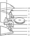
图1为本发明所提供的转盘式表冠的剖视图;1 is a cross-sectional view of a dial-type crown provided by the present invention;
图2为本发明所提供的转盘式表冠的爆炸图;Fig. 2 is the exploded view of the dial type crown provided by the present invention;
图3为转盘部分露出于壳体、部分位于壳体内的示意图;3 is a schematic view of the turntable partially exposed in the casing and partially located in the casing;
图4为本发明所提供的转盘式表冠的未按压状态的示意图。FIG. 4 is a schematic diagram of the unpressed state of the rotary crown provided by the present invention.
图1-图4中,附图标记包括:In Figures 1-4, reference numerals include:
1为上壳体、2为下壳体、3为转盘、4为转盘轴、5为螺母、6为弹性件、7为耐磨垫片、8为触发键、9为传感器、10为屏幕。1 is the upper shell, 2 is the lower shell, 3 is the turntable, 4 is the turntable shaft, 5 is the nut, 6 is the elastic piece, 7 is the wear-resistant gasket, 8 is the trigger key, 9 is the sensor, and 10 is the screen.
具体实施方式Detailed ways
下面将结合本发明实施例中的附图,对本发明实施例中的技术方案进行清楚、完整地描述,显然,所描述的实施例仅仅是本发明一部分实施例,而不是全部的实施例。基于本发明中的实施例,本领域普通技术人员在没有做出创造性劳动前提下所获得的所有其他实施例,都属于本发明保护的范围。The technical solutions in the embodiments of the present invention will be clearly and completely described below with reference to the accompanying drawings in the embodiments of the present invention. Obviously, the described embodiments are only a part of the embodiments of the present invention, but not all of the embodiments. Based on the embodiments of the present invention, all other embodiments obtained by those of ordinary skill in the art without creative efforts shall fall within the protection scope of the present invention.
本发明的核心是提供一种转盘式表冠,该转盘式表冠的使用操作方便,且能够节省壳体内的空间,为其他电子元件的安装让出空间。The core of the present invention is to provide a dial-type crown, which is easy to use and operate, and can save space in the casing and make room for the installation of other electronic components.
本发明的另一核心是提供一种包括上述转盘式表冠的智能手表。Another core of the present invention is to provide a smart watch including the above-mentioned rotary crown.
请参考图1至图4,图1为本发明所提供的转盘式表冠的剖视图;图2为本发明所提供的转盘式表冠的爆炸图;图3为转盘部分露出于壳体、部分位于壳体内的示意图;图4为本发明所提供的转盘式表冠的未按压状态的示意图。Please refer to FIGS. 1 to 4. FIG. 1 is a cross-sectional view of the turntable crown provided by the present invention; FIG. 2 is an exploded view of the turntable crown provided by the present invention; A schematic diagram inside the casing; FIG. 4 is a schematic diagram of the unpressed state of the dial-type crown provided by the present invention.
本申请提供的一种转盘式表冠,表冠为转盘结构的零件,用于实现智能手表的开关机、复位、显示控制或其他功能控制等等。转盘式表冠主要包括:转盘3、触发键8、传感器9以及壳体。其中壳体可以为表壳,或者仅为转盘式表冠的壳体。The present application provides a turntable crown, which is a part of a turntable structure, and is used to realize on/off, reset, display control or other function control of a smart watch. The turntable crown mainly includes: a
转盘3为盘类件,其铰接于壳体,具体为以转盘3的中心轴铰接于壳体,并且沿其自身的径向可相对于壳体移动,即垂直于铰接轴的方向移动,转盘3的部分盘面位于壳体内,同时部分露出于壳体,以便操作者进行拨转。The
触发键8设置于壳体内,与控制器电连接,触发键8为电子部件,当视线触发后,控制器进行对应的操作。触发键8具体可以为按键。当转盘3受外力沿径向移动时,转盘3可以实现触发键8的触发或解除触发。可选的,转盘3可以通过外力操作实现解除触发,或者也可以为当外力撤销后,转盘3自动复位以解除触发。可选的,触发键8为双向开关,转盘3的移动可以开启或关闭触发键8;或者触发键8为按键,转盘3靠近其移动以按下按键,远离其的移动可以使按键回弹。The
传感器9设置于壳体内,用于检测转盘3的转动状态,包括转动角度、转动方向和转动速度等,传感器9电连接于控制器。可选的,传感器9可以直接检测转盘的转动状态,或者通过检测与转盘3固定连接的其他部件,实现间接检测。The
上述结构中,转盘3可实现旋转运动,并可以实现径向移动,在旋转过程中,传感器9可以测量其转动状态,在径向移动过程中,转盘3可以用于实现触发键8的触发和解除,使用者对转盘3的旋转和按压操作能够分别使传感器9和触发键8获取相应的信息,传感器9和触发键8均连接控制器,控制器能够接收二者的感应后的信号,从而触发智能手表的相应操作。通常情况下传感器9获取的转动信息用于实现智能手表界面的缩放和滑动控制,触发键8获取的按动信息用于实现智能手表的界面的选择操作等。In the above structure, the
本申请提供的转盘式表冠包括旋转操作和径向移动操作,二者均可以通过单指完成,且转盘3的盘面部分位于壳体中,对壳体外部的空间占用较少,因而对转盘3的操作空间较大,能够避免与手腕运动产生干涉的同时,提升整体的美观性;转盘3的移动沿其径向方向,避免在壳体内、转盘的轴向上占用较大的空间,能够显著节省壳体内的空间,为其他电子元件的安装让出空间。The turntable crown provided by the present application includes a rotation operation and a radial movement operation, both of which can be completed by a single finger, and the disc surface part of the
在上述实施例的基础之上,转盘3设有转盘轴4,转盘轴4铰接于壳体,转盘轴4用于按压以实现触发键8的触发。On the basis of the above embodiment, the
请参考图4,图4中的箭头方向即为按压方向。转盘3的中轴即为转盘轴4,转盘轴4铰接于壳体的同时,还能够相对于铰接位置进行一定范围的径向移动,以便转盘3实现径向移动。需要说明的是,壳体或壳体内的固定结构需要对上述径向移动进行限位,即仅允许一个径向方向的直线移动,避免在不必要的方向产生移动。Please refer to FIG. 4 , the direction of the arrow in FIG. 4 is the pressing direction. The central axis of the
转盘轴4与转盘3为固定连接,或者二者为一体结构。转盘轴4的径向移动过程中实现对触发键8的触发,移动路径上可以具有定位部,以使转盘轴4易于保持在对应的位置。The
可选的,若智能手表中不需要转盘进行360度周向转动时,转盘轴4也可以为非中心位置的轴,相对应的,转盘3可以为非圆形件,可以为扇形等。Optionally, if the 360-degree circumferential rotation of the turntable is not required in the smart watch, the
上述实施例中可以利用移动路径上设置定位部,还可以是转盘轴4、转盘3中的至少一个通过弹性件6连接于壳体或壳体内的固定部,以实现无外力状态下的自动复位。在上述实施例的基础之上,转盘轴4通过弹性件6连接于壳体,受外力作用下,转盘3向弹性件6的回复力的反向移动,转盘轴4按压触发键8。In the above-mentioned embodiment, the positioning part can be set on the moving path, and at least one of the
弹性件6的作用是使转盘轴4保持在预设位置,以便远离触发键8,当有外力作用下,转动轴4靠近触发键8。弹性件6具体可以为弹簧、扭簧或者其他类型的弹性件。The function of the
在上述实施例的基础之上,转盘轴4的中部设置转盘3,转盘轴4的两端分别通过弹性件6连接壳体。On the basis of the above embodiment, a
转盘3位于转盘轴4的长度方向的中部,转盘轴4的两端为别设置上述弹性件,且两个弹性件6与转盘轴4的连接方式相同,作用力角度相同,作用效果相同,以使转盘轴4的两端受到相同的弹性回复力,从而保证转盘轴4、转盘3的稳定,避免操作过程中出现偏移。The
可选的,传感器9和触发键8分别设置于转盘3的两侧,也就是分别与转盘轴4的两端进行作用,以便充分利用转盘3两侧的空间,同时充分利用转盘轴4。Optionally, the
除了通过弹性件的方式实现复位以外,在上述实施例的基础之上,转盘轴4或壳体中至少一者设有磁性件,另一者设有与磁性件配合吸引的金属件或磁性配合件,以带动转盘3的复位。In addition to realizing the reset by means of an elastic member, on the basis of the above-mentioned embodiment, at least one of the
当受到外力作用时,转盘轴4克服受到的磁力作用进行移动,以实现对触发键8的操作;当外力撤销时,转盘轴4仅受到磁力作用,从而进行复位。可选的,转盘轴4、转盘3的复位也可以利用其它形式实现。When subjected to external force, the
在上述实施例的基础之上,传感器9设置于转盘轴4的一侧。传感器9检测转盘3的转动可以直接采集转盘轴4的转动信息,轴类件的转动测量易于盘类件的测量,因此,将传感器9设置于转盘轴4的径向位置,更加易于实现检测。On the basis of the above-mentioned embodiment, the
可选的,上述传感器9为激光传感器。Optionally, the
为了实现转盘3的盘面部分隐藏于壳体、部分露出于壳体,在上述任意一个实施例的基础之上,壳体设置有凹槽,凹槽的两侧壁面均设有铰接孔,转盘3位于凹槽中,且转盘轴4转动设于铰接孔中,且能够沿铰接孔进行预设距离的径向移动。In order to realize that the disk surface of the
具体地,凹槽设置于壳体的外表面,从而使转盘3能够部分安装于凹槽内的同时,部分露出于壳体。铰接孔为腰形孔,转盘轴4在铰接孔中能够沿径向移动。优选地,转盘3的盘面的大部分结构均可以位于凹槽内,以便露出壳体的部分为较小结构。上述预设距离的径向移动为抵抗弹性件或磁性件的移动。Specifically, the groove is provided on the outer surface of the casing, so that the
在上述任意一个实施例的基础之上,转盘3平行于壳体的屏幕10安装平面,转盘轴4垂直于壳体的屏幕10安装平面。On the basis of any of the above embodiments, the
请参考图1和图2,其中,转盘3的转动平面与屏幕安装平面大体平行,因而转盘轴4的延伸方向垂直于屏幕,转盘轴4的长度方向即垂直于屏幕,因此仅占壳体内的有限空间,为其他部件提供了更多的安装空间。Please refer to FIG. 1 and FIG. 2 , wherein the rotation plane of the
本申请提供的转盘式表冠中,转盘轴4与壳体之间设置有耐磨垫片7,以降低转盘轴4与壳体的磨损。In the turntable crown provided in the present application, a wear-
可选的,上述实施例中的壳体包括上壳体1和与之扣合连接的下壳体2,上述凹槽可以设置在二者之一,或者二者均具有凹槽的一部分,通过二者的扣合形成完整的凹槽。Optionally, the casing in the above-mentioned embodiment includes an
可选的,上述触发键8可以为Dome按键,或者为其他电子开关按键等。Optionally, the
请参考图1,上述结构的组装方法如下:Please refer to Figure 1, the assembly method of the above structure is as follows:
首先,将转盘3从外侧装入上表壳1上的凹槽内,接着,从顶部插入转盘轴4,使转盘轴4依次穿过上部的耐磨垫片7、上表壳1上的转轴孔、转盘3上的中心孔、下部的耐磨垫片7,然后从转盘轴4的下部套入螺母5锁附转盘3与转盘轴4。First, insert the
第二步,将上表壳1上的上部的弹簧挂柱与转盘轴4上部的弹簧挂柱通过弹性件6连接,并控制弹簧使之具有一定的预拉力,并采用同样的方法在上表壳1的下部的弹簧挂柱与转盘轴4下部的弹簧挂柱之间安装另一个弹性件6。The second step is to connect the upper spring hanging column on the
最后,在上壳体1内部安装激光传感器和Dome按键,使激光传感器的感应头正对转盘轴4下段的感应区域,并使Dome按键正对转轴上端;并将下壳体2与上壳体1连接以封闭上述结构。Finally, install the laser sensor and the Dome button inside the
除了上述各个实施例中所提供的转盘式表冠,本发明还提供一种包括上述实施例公开的转盘式表冠的智能手表,该智能手表的其他各部分的结构请参考现有技术,本文不再赘述。In addition to the turntable crown provided in the above embodiments, the present invention also provides a smart watch including the turntable crown disclosed in the above embodiments. For the structure of other parts of the smart watch, please refer to the prior art. No longer.
本说明书中各个实施例采用递进的方式描述,每个实施例重点说明的都是与其他实施例的不同之处,各个实施例之间相同相似部分互相参见即可。The various embodiments in this specification are described in a progressive manner, and each embodiment focuses on the differences from other embodiments, and the same and similar parts between the various embodiments can be referred to each other.
以上对本发明所提供的转盘式表冠和智能手表进行了详细介绍。本文中应用了具体个例对本发明的原理及实施方式进行了阐述,以上实施例的说明只是用于帮助理解本发明的方法及其核心思想。应当指出,对于本技术领域的普通技术人员来说,在不脱离本发明原理的前提下,还可以对本发明进行若干改进和修饰,这些改进和修饰也落入本发明权利要求的保护范围内。The turntable crown and the smart watch provided by the present invention have been described in detail above. The principles and implementations of the present invention are described herein by using specific examples, and the descriptions of the above embodiments are only used to help understand the method and the core idea of the present invention. It should be pointed out that for those skilled in the art, without departing from the principle of the present invention, several improvements and modifications can also be made to the present invention, and these improvements and modifications also fall within the protection scope of the claims of the present invention.
Claims (8)
Priority Applications (1)
| Application Number | Priority Date | Filing Date | Title |
|---|---|---|---|
| CN202011492830.2ACN112596365B (en) | 2020-12-16 | 2020-12-16 | A rotary crown and a smart watch |
Applications Claiming Priority (1)
| Application Number | Priority Date | Filing Date | Title |
|---|---|---|---|
| CN202011492830.2ACN112596365B (en) | 2020-12-16 | 2020-12-16 | A rotary crown and a smart watch |
Publications (2)
| Publication Number | Publication Date |
|---|---|
| CN112596365A CN112596365A (en) | 2021-04-02 |
| CN112596365Btrue CN112596365B (en) | 2022-07-22 |
Family
ID=75196631
Family Applications (1)
| Application Number | Title | Priority Date | Filing Date |
|---|---|---|---|
| CN202011492830.2AActiveCN112596365B (en) | 2020-12-16 | 2020-12-16 | A rotary crown and a smart watch |
Country Status (1)
| Country | Link |
|---|---|
| CN (1) | CN112596365B (en) |
Families Citing this family (3)
| Publication number | Priority date | Publication date | Assignee | Title |
|---|---|---|---|---|
| CN114002934B (en)* | 2021-10-29 | 2023-05-02 | 歌尔科技有限公司 | Intelligent watch and control method thereof |
| CN115509113B (en)* | 2022-09-26 | 2024-06-07 | 歌尔科技有限公司 | Wearable equipment |
| CN116500883B (en)* | 2023-06-29 | 2023-10-13 | 深圳市微克科技有限公司 | Horizontal crown |
Citations (7)
| Publication number | Priority date | Publication date | Assignee | Title |
|---|---|---|---|---|
| CN2603955Y (en)* | 2002-09-06 | 2004-02-18 | 游志豪 | A device for correcting or detecting the angular position of a rotating body |
| CN101057188A (en)* | 2004-11-11 | 2007-10-17 | 埃伯哈德股份有限公司 | Watch case |
| CN104898402A (en)* | 2014-03-06 | 2015-09-09 | 精工爱普生株式会社 | Electronic timepiece and movement |
| CN105117013A (en)* | 2015-08-26 | 2015-12-02 | 广东欧珀移动通信有限公司 | Intelligent watch unlocking method and intelligent watch |
| CN105389074A (en)* | 2015-07-28 | 2016-03-09 | 广东欧珀移动通信有限公司 | Smart watch control method and smart watch |
| CN105556433A (en)* | 2013-08-09 | 2016-05-04 | 苹果公司 | Tactile switches for electronic devices |
| CN111624868A (en)* | 2020-06-05 | 2020-09-04 | 北京小米移动软件有限公司 | Adjustment mechanism, electronic device, and information processing method |
Family Cites Families (8)
| Publication number | Priority date | Publication date | Assignee | Title |
|---|---|---|---|---|
| GB1322982A (en)* | 1969-07-11 | 1973-07-11 | Sankyo Seiki Seisakusho Kk | Digital clock |
| GB1340729A (en)* | 1970-11-18 | 1974-01-30 | Suwa Seikosha Kk | Gearing e g in a timepiece |
| CH569318B5 (en)* | 1973-06-29 | 1975-11-14 | Soguel Rene | |
| CH696174A5 (en)* | 2002-05-10 | 2007-01-31 | Supraventures Ag | Watch with a multifunctional crown. |
| US20140362673A1 (en)* | 2013-06-11 | 2014-12-11 | David Earl | Watch with enclosed crown |
| CN106292261B (en)* | 2016-08-30 | 2019-08-20 | 歌尔股份有限公司 | A kind of installation method of smartwatch and its physical button component |
| CN206489223U (en)* | 2016-12-30 | 2017-09-12 | 华通信安(北京)科技发展有限公司 | A kind of antenna setting lockable mechanism |
| CN207571490U (en)* | 2017-11-14 | 2018-07-03 | 惠州Tcl移动通信有限公司 | A kind of crown structure and smartwatch |
- 2020
- 2020-12-16CNCN202011492830.2Apatent/CN112596365B/enactiveActive
Patent Citations (7)
| Publication number | Priority date | Publication date | Assignee | Title |
|---|---|---|---|---|
| CN2603955Y (en)* | 2002-09-06 | 2004-02-18 | 游志豪 | A device for correcting or detecting the angular position of a rotating body |
| CN101057188A (en)* | 2004-11-11 | 2007-10-17 | 埃伯哈德股份有限公司 | Watch case |
| CN105556433A (en)* | 2013-08-09 | 2016-05-04 | 苹果公司 | Tactile switches for electronic devices |
| CN104898402A (en)* | 2014-03-06 | 2015-09-09 | 精工爱普生株式会社 | Electronic timepiece and movement |
| CN105389074A (en)* | 2015-07-28 | 2016-03-09 | 广东欧珀移动通信有限公司 | Smart watch control method and smart watch |
| CN105117013A (en)* | 2015-08-26 | 2015-12-02 | 广东欧珀移动通信有限公司 | Intelligent watch unlocking method and intelligent watch |
| CN111624868A (en)* | 2020-06-05 | 2020-09-04 | 北京小米移动软件有限公司 | Adjustment mechanism, electronic device, and information processing method |
Also Published As
| Publication number | Publication date |
|---|---|
| CN112596365A (en) | 2021-04-02 |
Similar Documents
| Publication | Publication Date | Title |
|---|---|---|
| CN112596365B (en) | A rotary crown and a smart watch | |
| KR100896055B1 (en) | Mobile terminal with rotary input device and display method thereof | |
| KR20180103969A (en) | Electronic devices and methods of operating such electronic devices | |
| JP2005292139A (en) | Push-button clock | |
| CN114566398B (en) | Electronic equipment | |
| CN110933210A (en) | Electronic device | |
| TWI715910B (en) | Communication device | |
| CN221884979U (en) | Knobs and electrical appliances | |
| CN113391675A (en) | Wrist-worn device, device false touch prevention method and storage medium | |
| CN111090232B (en) | Electronic device | |
| CN208015703U (en) | A kind of novel mechanical optical axis button | |
| JP3828676B2 (en) | Pointing device | |
| CN114509930B (en) | Electronic watch crown module and electronic equipment | |
| CN111180237A (en) | Electronic device | |
| CN214122708U (en) | Wearable equipment and crown adjusting mechanism thereof | |
| TW201324250A (en) | Mouse device | |
| CN222994842U (en) | Linkage type adjusting mechanism for watch and watch | |
| US20210149501A1 (en) | Mouse Device | |
| CN111815894A (en) | Smoke alarm | |
| CN114002934B (en) | Intelligent watch and control method thereof | |
| CN208224889U (en) | A kind of knob | |
| CN214623603U (en) | A mouse structure that can adjust the motion of the scroll wheel | |
| CN115857308B (en) | Key assemblies, electronic devices, and wearable devices | |
| CN201262718Y (en) | Sliding type multi-directional input device | |
| US20250096802A1 (en) | Control key and electronic device |
Legal Events
| Date | Code | Title | Description |
|---|---|---|---|
| PB01 | Publication | ||
| PB01 | Publication | ||
| SE01 | Entry into force of request for substantive examination | ||
| SE01 | Entry into force of request for substantive examination | ||
| GR01 | Patent grant | ||
| GR01 | Patent grant | ||
| TR01 | Transfer of patent right | ||
| TR01 | Transfer of patent right | Effective date of registration:20221219 Address after:266104 No. 500, Songling Road, Laoshan District, Qingdao, Shandong Patentee after:GOERTEK TECHNOLOGY Co.,Ltd. Address before:261031 north of Yuqing street, east of Dongming Road, high tech Zone, Weifang City, Shandong Province (Room 502, Geer electronics office building) Patentee before:GoerTek Optical Technology Co.,Ltd. |