CN112594283B - Lubrication ducts and slide units with lubrication ducts - Google Patents
Lubrication ducts and slide units with lubrication ductsDownload PDFInfo
- Publication number
- CN112594283B CN112594283BCN202010003772.6ACN202010003772ACN112594283BCN 112594283 BCN112594283 BCN 112594283BCN 202010003772 ACN202010003772 ACN 202010003772ACN 112594283 BCN112594283 BCN 112594283B
- Authority
- CN
- China
- Prior art keywords
- lubricating
- axis
- oil storage
- annular surface
- hole
- Prior art date
- Legal status (The legal status is an assumption and is not a legal conclusion. Google has not performed a legal analysis and makes no representation as to the accuracy of the status listed.)
- Active
Links
- 238000005461lubricationMethods0.000titleabstractdescription10
- 230000001050lubricating effectEffects0.000claimsabstractdescription107
- 238000003860storageMethods0.000claimsabstractdescription56
- 239000011148porous materialSubstances0.000claimsabstractdescription10
- 229920001903high density polyethylenePolymers0.000claimsdescription6
- 239000004700high-density polyethyleneSubstances0.000claimsdescription6
- 238000007731hot pressingMethods0.000claimsdescription6
- 239000000843powderSubstances0.000claimsdescription6
- 238000002347injectionMethods0.000claimsdescription5
- 239000007924injectionSubstances0.000claimsdescription5
- 238000005452bendingMethods0.000claimsdescription4
- 230000000149penetrating effectEffects0.000claimsdescription2
- 239000003921oilSubstances0.000description62
- 239000004519greaseSubstances0.000description8
- 238000012423maintenanceMethods0.000description8
- 230000007774longtermEffects0.000description7
- 239000010687lubricating oilSubstances0.000description6
- 230000014759maintenance of locationEffects0.000description6
- 230000000694effectsEffects0.000description4
- 229920000642polymerPolymers0.000description3
- 238000010586diagramMethods0.000description2
- 238000000034methodMethods0.000description2
- 230000009286beneficial effectEffects0.000description1
- 238000004891communicationMethods0.000description1
- 238000005516engineering processMethods0.000description1
- 230000003631expected effectEffects0.000description1
- 238000003754machiningMethods0.000description1
- 239000000463materialSubstances0.000description1
- 230000002093peripheral effectEffects0.000description1
- 229920006395saturated elastomerPolymers0.000description1
Images


Classifications
- F—MECHANICAL ENGINEERING; LIGHTING; HEATING; WEAPONS; BLASTING
- F16—ENGINEERING ELEMENTS AND UNITS; GENERAL MEASURES FOR PRODUCING AND MAINTAINING EFFECTIVE FUNCTIONING OF MACHINES OR INSTALLATIONS; THERMAL INSULATION IN GENERAL
- F16N—LUBRICATING
- F16N11/00—Arrangements for supplying grease from a stationary reservoir or the equivalent in or on the machine or member to be lubricated; Grease cups
- F—MECHANICAL ENGINEERING; LIGHTING; HEATING; WEAPONS; BLASTING
- F16—ENGINEERING ELEMENTS AND UNITS; GENERAL MEASURES FOR PRODUCING AND MAINTAINING EFFECTIVE FUNCTIONING OF MACHINES OR INSTALLATIONS; THERMAL INSULATION IN GENERAL
- F16C—SHAFTS; FLEXIBLE SHAFTS; ELEMENTS OR CRANKSHAFT MECHANISMS; ROTARY BODIES OTHER THAN GEARING ELEMENTS; BEARINGS
- F16C33/00—Parts of bearings; Special methods for making bearings or parts thereof
- F16C33/02—Parts of sliding-contact bearings
- F16C33/04—Brasses; Bushes; Linings
- F16C33/06—Sliding surface mainly made of metal
- F16C33/10—Construction relative to lubrication
- F16C33/1025—Construction relative to lubrication with liquid, e.g. oil, as lubricant
- F—MECHANICAL ENGINEERING; LIGHTING; HEATING; WEAPONS; BLASTING
- F16—ENGINEERING ELEMENTS AND UNITS; GENERAL MEASURES FOR PRODUCING AND MAINTAINING EFFECTIVE FUNCTIONING OF MACHINES OR INSTALLATIONS; THERMAL INSULATION IN GENERAL
- F16C—SHAFTS; FLEXIBLE SHAFTS; ELEMENTS OR CRANKSHAFT MECHANISMS; ROTARY BODIES OTHER THAN GEARING ELEMENTS; BEARINGS
- F16C33/00—Parts of bearings; Special methods for making bearings or parts thereof
- F16C33/30—Parts of ball or roller bearings
- F16C33/66—Special parts or details in view of lubrication
- F16C33/6637—Special parts or details in view of lubrication with liquid lubricant
- F16C33/664—Retaining the liquid in or near the bearing
- F16C33/6648—Retaining the liquid in or near the bearing in a porous or resinous body, e.g. a cage impregnated with the liquid
- C—CHEMISTRY; METALLURGY
- C08—ORGANIC MACROMOLECULAR COMPOUNDS; THEIR PREPARATION OR CHEMICAL WORKING-UP; COMPOSITIONS BASED THEREON
- C08L—COMPOSITIONS OF MACROMOLECULAR COMPOUNDS
- C08L23/00—Compositions of homopolymers or copolymers of unsaturated aliphatic hydrocarbons having only one carbon-to-carbon double bond; Compositions of derivatives of such polymers
- C08L23/02—Compositions of homopolymers or copolymers of unsaturated aliphatic hydrocarbons having only one carbon-to-carbon double bond; Compositions of derivatives of such polymers not modified by chemical after-treatment
- C08L23/04—Homopolymers or copolymers of ethene
- C08L23/06—Polyethene
- F—MECHANICAL ENGINEERING; LIGHTING; HEATING; WEAPONS; BLASTING
- F16—ENGINEERING ELEMENTS AND UNITS; GENERAL MEASURES FOR PRODUCING AND MAINTAINING EFFECTIVE FUNCTIONING OF MACHINES OR INSTALLATIONS; THERMAL INSULATION IN GENERAL
- F16C—SHAFTS; FLEXIBLE SHAFTS; ELEMENTS OR CRANKSHAFT MECHANISMS; ROTARY BODIES OTHER THAN GEARING ELEMENTS; BEARINGS
- F16C29/00—Bearings for parts moving only linearly
- F16C29/04—Ball or roller bearings
- F16C29/043—Ball or roller bearings with two massive rectangular rails having facing grooves
- F—MECHANICAL ENGINEERING; LIGHTING; HEATING; WEAPONS; BLASTING
- F16—ENGINEERING ELEMENTS AND UNITS; GENERAL MEASURES FOR PRODUCING AND MAINTAINING EFFECTIVE FUNCTIONING OF MACHINES OR INSTALLATIONS; THERMAL INSULATION IN GENERAL
- F16C—SHAFTS; FLEXIBLE SHAFTS; ELEMENTS OR CRANKSHAFT MECHANISMS; ROTARY BODIES OTHER THAN GEARING ELEMENTS; BEARINGS
- F16C29/00—Bearings for parts moving only linearly
- F16C29/04—Ball or roller bearings
- F16C29/06—Ball or roller bearings in which the rolling bodies circulate partly without carrying load
- F16C29/0602—Details of the bearing body or carriage or parts thereof, e.g. methods for manufacturing or assembly
- F16C29/0609—Details of the bearing body or carriage or parts thereof, e.g. methods for manufacturing or assembly of the ends of the bearing body or carriage where the rolling elements change direction, e.g. end caps
- F—MECHANICAL ENGINEERING; LIGHTING; HEATING; WEAPONS; BLASTING
- F16—ENGINEERING ELEMENTS AND UNITS; GENERAL MEASURES FOR PRODUCING AND MAINTAINING EFFECTIVE FUNCTIONING OF MACHINES OR INSTALLATIONS; THERMAL INSULATION IN GENERAL
- F16C—SHAFTS; FLEXIBLE SHAFTS; ELEMENTS OR CRANKSHAFT MECHANISMS; ROTARY BODIES OTHER THAN GEARING ELEMENTS; BEARINGS
- F16C29/00—Bearings for parts moving only linearly
- F16C29/04—Ball or roller bearings
- F16C29/06—Ball or roller bearings in which the rolling bodies circulate partly without carrying load
- F16C29/0602—Details of the bearing body or carriage or parts thereof, e.g. methods for manufacturing or assembly
- F16C29/0611—Details of the bearing body or carriage or parts thereof, e.g. methods for manufacturing or assembly of the return passages, i.e. the passages where the rolling elements do not carry load
- F—MECHANICAL ENGINEERING; LIGHTING; HEATING; WEAPONS; BLASTING
- F16—ENGINEERING ELEMENTS AND UNITS; GENERAL MEASURES FOR PRODUCING AND MAINTAINING EFFECTIVE FUNCTIONING OF MACHINES OR INSTALLATIONS; THERMAL INSULATION IN GENERAL
- F16C—SHAFTS; FLEXIBLE SHAFTS; ELEMENTS OR CRANKSHAFT MECHANISMS; ROTARY BODIES OTHER THAN GEARING ELEMENTS; BEARINGS
- F16C29/00—Bearings for parts moving only linearly
- F16C29/04—Ball or roller bearings
- F16C29/06—Ball or roller bearings in which the rolling bodies circulate partly without carrying load
- F16C29/0614—Ball or roller bearings in which the rolling bodies circulate partly without carrying load with a shoe type bearing body, e.g. a body facing one side of the guide rail or track only
- F—MECHANICAL ENGINEERING; LIGHTING; HEATING; WEAPONS; BLASTING
- F16—ENGINEERING ELEMENTS AND UNITS; GENERAL MEASURES FOR PRODUCING AND MAINTAINING EFFECTIVE FUNCTIONING OF MACHINES OR INSTALLATIONS; THERMAL INSULATION IN GENERAL
- F16C—SHAFTS; FLEXIBLE SHAFTS; ELEMENTS OR CRANKSHAFT MECHANISMS; ROTARY BODIES OTHER THAN GEARING ELEMENTS; BEARINGS
- F16C29/00—Bearings for parts moving only linearly
- F16C29/04—Ball or roller bearings
- F16C29/06—Ball or roller bearings in which the rolling bodies circulate partly without carrying load
- F16C29/0633—Ball or roller bearings in which the rolling bodies circulate partly without carrying load with a bearing body defining a U-shaped carriage, i.e. surrounding a guide rail or track on three sides
- F16C29/0635—Ball or roller bearings in which the rolling bodies circulate partly without carrying load with a bearing body defining a U-shaped carriage, i.e. surrounding a guide rail or track on three sides whereby the return paths are provided as bores in a main body of the U-shaped carriage, e.g. the main body of the U-shaped carriage is a single part with end caps provided at each end
- F16C29/0638—Ball or roller bearings in which the rolling bodies circulate partly without carrying load with a bearing body defining a U-shaped carriage, i.e. surrounding a guide rail or track on three sides whereby the return paths are provided as bores in a main body of the U-shaped carriage, e.g. the main body of the U-shaped carriage is a single part with end caps provided at each end with balls
- F16C29/064—Ball or roller bearings in which the rolling bodies circulate partly without carrying load with a bearing body defining a U-shaped carriage, i.e. surrounding a guide rail or track on three sides whereby the return paths are provided as bores in a main body of the U-shaped carriage, e.g. the main body of the U-shaped carriage is a single part with end caps provided at each end with balls with two rows of balls, one on each side of the rail
- F—MECHANICAL ENGINEERING; LIGHTING; HEATING; WEAPONS; BLASTING
- F16—ENGINEERING ELEMENTS AND UNITS; GENERAL MEASURES FOR PRODUCING AND MAINTAINING EFFECTIVE FUNCTIONING OF MACHINES OR INSTALLATIONS; THERMAL INSULATION IN GENERAL
- F16C—SHAFTS; FLEXIBLE SHAFTS; ELEMENTS OR CRANKSHAFT MECHANISMS; ROTARY BODIES OTHER THAN GEARING ELEMENTS; BEARINGS
- F16C29/00—Bearings for parts moving only linearly
- F16C29/04—Ball or roller bearings
- F16C29/06—Ball or roller bearings in which the rolling bodies circulate partly without carrying load
- F16C29/0633—Ball or roller bearings in which the rolling bodies circulate partly without carrying load with a bearing body defining a U-shaped carriage, i.e. surrounding a guide rail or track on three sides
- F16C29/0635—Ball or roller bearings in which the rolling bodies circulate partly without carrying load with a bearing body defining a U-shaped carriage, i.e. surrounding a guide rail or track on three sides whereby the return paths are provided as bores in a main body of the U-shaped carriage, e.g. the main body of the U-shaped carriage is a single part with end caps provided at each end
- F16C29/065—Ball or roller bearings in which the rolling bodies circulate partly without carrying load with a bearing body defining a U-shaped carriage, i.e. surrounding a guide rail or track on three sides whereby the return paths are provided as bores in a main body of the U-shaped carriage, e.g. the main body of the U-shaped carriage is a single part with end caps provided at each end with rollers
- F—MECHANICAL ENGINEERING; LIGHTING; HEATING; WEAPONS; BLASTING
- F16—ENGINEERING ELEMENTS AND UNITS; GENERAL MEASURES FOR PRODUCING AND MAINTAINING EFFECTIVE FUNCTIONING OF MACHINES OR INSTALLATIONS; THERMAL INSULATION IN GENERAL
- F16C—SHAFTS; FLEXIBLE SHAFTS; ELEMENTS OR CRANKSHAFT MECHANISMS; ROTARY BODIES OTHER THAN GEARING ELEMENTS; BEARINGS
- F16C29/00—Bearings for parts moving only linearly
- F16C29/04—Ball or roller bearings
- F16C29/06—Ball or roller bearings in which the rolling bodies circulate partly without carrying load
- F16C29/0633—Ball or roller bearings in which the rolling bodies circulate partly without carrying load with a bearing body defining a U-shaped carriage, i.e. surrounding a guide rail or track on three sides
- F16C29/0652—Ball or roller bearings in which the rolling bodies circulate partly without carrying load with a bearing body defining a U-shaped carriage, i.e. surrounding a guide rail or track on three sides whereby the return paths are at least partly defined by separate parts, e.g. covers attached to the legs of the main body of the U-shaped carriage
- F16C29/0666—Ball or roller bearings in which the rolling bodies circulate partly without carrying load with a bearing body defining a U-shaped carriage, i.e. surrounding a guide rail or track on three sides whereby the return paths are at least partly defined by separate parts, e.g. covers attached to the legs of the main body of the U-shaped carriage with rollers
- F—MECHANICAL ENGINEERING; LIGHTING; HEATING; WEAPONS; BLASTING
- F16—ENGINEERING ELEMENTS AND UNITS; GENERAL MEASURES FOR PRODUCING AND MAINTAINING EFFECTIVE FUNCTIONING OF MACHINES OR INSTALLATIONS; THERMAL INSULATION IN GENERAL
- F16C—SHAFTS; FLEXIBLE SHAFTS; ELEMENTS OR CRANKSHAFT MECHANISMS; ROTARY BODIES OTHER THAN GEARING ELEMENTS; BEARINGS
- F16C33/00—Parts of bearings; Special methods for making bearings or parts thereof
- F16C33/30—Parts of ball or roller bearings
- F16C33/66—Special parts or details in view of lubrication
- F16C33/6637—Special parts or details in view of lubrication with liquid lubricant
- F16C33/6659—Details of supply of the liquid to the bearing, e.g. passages or nozzles
- F—MECHANICAL ENGINEERING; LIGHTING; HEATING; WEAPONS; BLASTING
- F16—ENGINEERING ELEMENTS AND UNITS; GENERAL MEASURES FOR PRODUCING AND MAINTAINING EFFECTIVE FUNCTIONING OF MACHINES OR INSTALLATIONS; THERMAL INSULATION IN GENERAL
- F16C—SHAFTS; FLEXIBLE SHAFTS; ELEMENTS OR CRANKSHAFT MECHANISMS; ROTARY BODIES OTHER THAN GEARING ELEMENTS; BEARINGS
- F16C33/00—Parts of bearings; Special methods for making bearings or parts thereof
- F16C33/30—Parts of ball or roller bearings
- F16C33/66—Special parts or details in view of lubrication
- F16C33/6637—Special parts or details in view of lubrication with liquid lubricant
- F16C33/6681—Details of distribution or circulation inside the bearing, e.g. grooves on the cage or passages in the rolling elements
- F—MECHANICAL ENGINEERING; LIGHTING; HEATING; WEAPONS; BLASTING
- F16—ENGINEERING ELEMENTS AND UNITS; GENERAL MEASURES FOR PRODUCING AND MAINTAINING EFFECTIVE FUNCTIONING OF MACHINES OR INSTALLATIONS; THERMAL INSULATION IN GENERAL
- F16N—LUBRICATING
- F16N7/00—Arrangements for supplying oil or unspecified lubricant from a stationary reservoir or the equivalent in or on the machine or member to be lubricated
- F16N7/36—Arrangements for supplying oil or unspecified lubricant from a stationary reservoir or the equivalent in or on the machine or member to be lubricated with feed by pumping action of the member to be lubricated or of a shaft of the machine; Centrifugal lubrication
- F—MECHANICAL ENGINEERING; LIGHTING; HEATING; WEAPONS; BLASTING
- F16—ENGINEERING ELEMENTS AND UNITS; GENERAL MEASURES FOR PRODUCING AND MAINTAINING EFFECTIVE FUNCTIONING OF MACHINES OR INSTALLATIONS; THERMAL INSULATION IN GENERAL
- F16N—LUBRICATING
- F16N7/00—Arrangements for supplying oil or unspecified lubricant from a stationary reservoir or the equivalent in or on the machine or member to be lubricated
- F16N7/38—Arrangements for supplying oil or unspecified lubricant from a stationary reservoir or the equivalent in or on the machine or member to be lubricated with a separate pump; Central lubrication systems
- F16N7/385—Central lubrication systems
- C—CHEMISTRY; METALLURGY
- C08—ORGANIC MACROMOLECULAR COMPOUNDS; THEIR PREPARATION OR CHEMICAL WORKING-UP; COMPOSITIONS BASED THEREON
- C08L—COMPOSITIONS OF MACROMOLECULAR COMPOUNDS
- C08L2203/00—Applications
- C08L2203/30—Applications used for thermoforming
- C—CHEMISTRY; METALLURGY
- C08—ORGANIC MACROMOLECULAR COMPOUNDS; THEIR PREPARATION OR CHEMICAL WORKING-UP; COMPOSITIONS BASED THEREON
- C08L—COMPOSITIONS OF MACROMOLECULAR COMPOUNDS
- C08L2207/00—Properties characterising the ingredient of the composition
- C08L2207/06—Properties of polyethylene
- C08L2207/062—HDPE
- F—MECHANICAL ENGINEERING; LIGHTING; HEATING; WEAPONS; BLASTING
- F16—ENGINEERING ELEMENTS AND UNITS; GENERAL MEASURES FOR PRODUCING AND MAINTAINING EFFECTIVE FUNCTIONING OF MACHINES OR INSTALLATIONS; THERMAL INSULATION IN GENERAL
- F16N—LUBRICATING
- F16N2210/00—Applications
Landscapes
- Engineering & Computer Science (AREA)
- General Engineering & Computer Science (AREA)
- Mechanical Engineering (AREA)
- Chemical & Material Sciences (AREA)
- Oil, Petroleum & Natural Gas (AREA)
- Health & Medical Sciences (AREA)
- Chemical Kinetics & Catalysis (AREA)
- Medicinal Chemistry (AREA)
- Polymers & Plastics (AREA)
- Organic Chemistry (AREA)
- Bearings For Parts Moving Linearly (AREA)
- Rolling Contact Bearings (AREA)
Abstract
Translated fromChinese
Description
Translated fromChinese技术领域technical field
本发明涉及一种线性滑台装置,特别是涉及一种润滑导管及具润滑导管的滑台装置。The invention relates to a linear sliding table device, in particular to a lubricating conduit and a sliding table device with the lubricating conduit.
背景技术Background technique
一般普遍应用于机械的滑台装置,主要具有一个线性轨道、一个滑动块、两对循环器,以及两个设置于该线性轨道、该滑动块与所述循环器之间的滚珠组。该滑动块设于该线性轨道上,并供一个承载体结合定位。当一个驱动模块驱动该滑动块在该线性轨道的一个轨道槽移动时,该承载体上的一个工作机构会被带动而进行线性移动。A sliding table device generally used in machinery mainly has a linear track, a sliding block, two pairs of circulators, and two ball groups arranged between the linear track, the sliding block and the circulator. The sliding block is arranged on the linear track and is combined and positioned by a carrier. When a driving module drives the sliding block to move in a track groove of the linear track, a working mechanism on the carrier will be driven to move linearly.
在现有的滑台装置中,润滑油从该滑动块注入后,经过一个油体通道进入两个供所述滚珠组安装的滚珠通孔中且直接润滑所述滚珠组,然而,在该滑台装置使用过程中,润滑油脂无法持续保持于该滑台装置内,需定期保养注入润滑油,确保所述滚珠组的润滑并延长该滑台装置的使用寿命。因此,如何提供一种具储油、润滑的滑座,能够借由改变其结构而达到长期保油及良好的润滑效果,减少定期保养频率,进而提升操作的整体效率,实为当前重要课题之一。In the existing sliding table device, after the lubricating oil is injected from the sliding block, it enters the two ball through holes for installing the ball group through an oil body channel and directly lubricates the ball group. However, in this sliding block During the use of the table device, the lubricating grease cannot be maintained in the sliding table device continuously, and it is necessary to regularly maintain and inject lubricating oil to ensure the lubrication of the ball group and prolong the service life of the sliding table device. Therefore, how to provide a sliding seat with oil storage and lubrication, which can achieve long-term oil retention and good lubrication effect by changing its structure, reduce the frequency of regular maintenance, and thus improve the overall efficiency of the operation, is an important issue at present. one.
在此之前,已有在该滑动块内部设置润滑组件的设计,并借由该润滑组件能储油并释放润滑油脂,以达到润滑该轨道槽与循环运作的滚珠组的目的。Previously, a lubricating component has been designed inside the sliding block, and the lubricating component can store oil and release the lubricating grease, so as to achieve the purpose of lubricating the orbital groove and the circulating ball group.
例如,日本特开200141304号,其所设置的润滑构件是含润滑油的聚合物构件,利用其材质本身具有的多孔特性可以储油,并逐渐渗出到滚珠螺杆。另外,在润滑构件和滚珠螺母之间所产生的缝隙虽然也能用作润滑脂贮存器,但是润滑构件和滚珠螺母之间的缝隙只有相对转动的余隙,储油量有限。For example, in Japanese Patent Application Laid-Open No. 200141304, the lubricating member provided is a polymer member containing lubricating oil, which can store oil by utilizing the porous property of the material itself, and gradually seep out to the ball screw. In addition, although the gap formed between the lubricating member and the ball nut can also be used as a grease reservoir, the gap between the lubricating member and the ball nut has only a relative rotation clearance, and the oil storage capacity is limited.
另外,日本特许第3733654号、特许第3950540号、特许第4502290号、特许第6196128号等专利案,也都是利用含润滑油的聚合物构件来达到相对转动对象之间的润滑效果,但是这些专利案所揭示的聚合物构件的储油量有限,仍然无法解决长期保油及良好的润滑效果的问题,且必须经常添加润滑油及保养的操作,使用上并不方便。In addition, Japanese Patent No. 3733654, Patent No. 3950540, Patent No. 4502290, Patent No. 6196128 and other patents also use lubricating oil-containing polymer components to achieve the lubricating effect between relatively rotating objects, but these The polymer components disclosed in the patent case have limited oil storage capacity, and still cannot solve the problems of long-term oil retention and good lubricating effect, and the operation of frequent addition of lubricating oil and maintenance is inconvenient in use.
发明内容SUMMARY OF THE INVENTION
本发明的一个目的在于提供一种能解决长期保油且结构简单的润滑导管。An object of the present invention is to provide a lubricating conduit with a simple structure that can solve long-term oil retention.
本发明的另一个目的在于提供一种能解决长期保油且保养方便的具润滑导管的滑台装置。Another object of the present invention is to provide a sliding table device with a lubricating conduit that can solve the problem of long-term oil retention and easy maintenance.
本发明的润滑导管,制成中空管状且沿轴线延伸,所述润滑导管以多孔性材质制成,并包括围绕所述轴线的内环面,以及相反于所述内环面的外环面,所述内环面垂直于所述轴线的截面轮廓呈非圆形,所述内环面具有数个围绕所述轴线呈间隔设置的内储油槽,以及数个分别介于每两个内储油槽之间的导滑部,所述内储油槽与所述导滑部共同界定出内孔,所述内储油槽相对于所述导滑部朝所述外环面凹设。The lubricating conduit of the present invention is made into a hollow tubular shape and extends along an axis, the lubricating conduit is made of porous material, and includes an inner annular surface surrounding the axis, and an outer annular surface opposite to the inner annular surface, The cross-sectional profile of the inner annular surface perpendicular to the axis is non-circular, and the inner annular surface has a plurality of inner oil storage grooves arranged at intervals around the axis, and a plurality of inner oil storage grooves respectively interposed between every two inner oil storage grooves. The inner oil storage groove and the guiding sliding part jointly define an inner hole, and the inner oil storage groove is recessed toward the outer annular surface relative to the guiding sliding part.
本发明的润滑导管,所述外环面垂直于所述轴线的截面轮廓也呈非圆形,所述外环面具有数个围绕所述轴线呈间隔设置的凸出部,以及数个分别介于每两个凸出部之间的圆弧部,所述凸出部相对于所述圆弧部朝远离于所述轴线的外部凸出,每一个圆弧部与相邻两个凸出部共同界定出外储油槽。In the lubricating conduit of the present invention, the cross-sectional profile of the outer annular surface perpendicular to the axis is also non-circular, and the outer annular surface has a plurality of protruding parts arranged at intervals around the axis, and a plurality of In the arc portion between each two protruding portions, the protruding portion protrudes toward the outside away from the axis relative to the arc portion, and each arc portion is connected to two adjacent protruding portions. Commonly define the external oil storage tank.
本发明的润滑导管,还包括连通所述内环面与所述外环面之间的通孔,所述通孔设置于其中一个凸出部,以及与所述凸出部对应的内储油槽之间。The lubricating conduit of the present invention further comprises a through hole communicating between the inner annular surface and the outer annular surface, the through hole is provided in one of the protruding parts, and an inner oil storage groove corresponding to the protruding part between.
本发明的润滑导管,所述润滑导管采用高密度聚乙烯粉末热压成型。In the lubricating conduit of the present invention, the lubricating conduit is formed by hot pressing of high-density polyethylene powder.
本发明的具润滑导管的滑台装置,包含线性轨道、滑座、两个润滑导管、两对循环器及两个滚珠组,所述线性轨道沿长轴向延伸,并具有一对沿垂直于所述长轴向的横轴向呈相对设置的侧壁,以及一对分别凹设于所述侧壁且沿所述长轴向延伸的外轨槽,所述滑座能沿所述长轴向滑动且套设于所述线性轨道上,并具有两个沿所述长轴向呈相反设置的端面、一对分别对应于所述外轨槽且沿所述长轴向贯穿所述端面的滚珠通孔、能连通至所述滚珠通孔的注油通道,以及一对与所述外轨槽相对设置的内轨槽,所述润滑导管以多孔性材质制成中空管状,且分别沿轴线延伸并分别安装于所述滚珠通孔中,每一个润滑导管包括围绕所述轴线的内环面,以及相反于所述内环面的外环面,所述内环面垂直于所述轴线的截面轮廓呈非圆形,所述内环面具有数个围绕所述轴线呈间隔设置的内储油槽,以及数个分别介于每两个内储油槽之间的导滑部,所述内储油槽与所述导滑部共同界定出内孔,所述内储油槽相对于所述导滑部朝所述外环面凹设,所述循环器分别安装于所述滑座,并各具有连通于所对应的内孔与所对应的外轨槽之间的循环孔,每一个润滑导管与所对应的循环器、外轨槽、内轨槽共同产生滚珠循环通道,所述滚珠组分别在所述滚珠循环通道中循环运转。The sliding table device with lubricating conduits of the present invention comprises a linear rail, a sliding seat, two lubricating conduits, two pairs of circulators and two ball groups, the linear rails extend along the long axis, and have a pair of The lateral axis of the long axis is oppositely arranged side walls, and a pair of outer rail grooves are respectively recessed in the side walls and extend along the long axis, the sliding seat can be along the long axis It slides upward and is sleeved on the linear track, and has two end faces arranged oppositely along the long axis, and a pair of grooves corresponding to the outer rail grooves and penetrating the end faces along the long axis respectively. A ball through hole, an oil injection channel that can be communicated to the ball through hole, and a pair of inner rail grooves opposite to the outer rail groove, the lubricating conduit is made of a porous material in a hollow tubular shape, and respectively extends along the axis and are respectively installed in the ball through holes, each lubricating conduit includes an inner annular surface surrounding the axis, and an outer annular surface opposite to the inner annular surface, and the inner annular surface is perpendicular to the cross section of the axis The contour is non-circular, the inner annular surface has a plurality of inner oil storage grooves arranged at intervals around the axis, and a plurality of guide sliding parts respectively between every two inner oil storage grooves, the inner oil storage grooves The inner hole is defined together with the guide sliding part, the inner oil storage groove is recessed toward the outer ring surface relative to the guide sliding part, the circulators are respectively installed on the sliding seat, and each has a communication The circulation hole between the corresponding inner hole and the corresponding outer rail groove, each lubricating conduit and the corresponding circulator, outer rail groove and inner rail groove jointly generate a ball circulation channel, and the ball groups are respectively in the It circulates in the ball circulation channel.
本发明的具润滑导管的滑台装置,每一个润滑导管的外环面垂直于所述轴线的截面轮廓也呈非圆形,所述外环面具有数个围绕所述轴线呈间隔设置的凸出部,以及数个分别介于每两个凸出部之间的圆弧部,所述凸出部相对于所述圆弧部朝远离于所述轴线的外部凸出,每一个圆弧部与相邻两个凸出部共同界定出外储油槽。In the slide table device with lubricating ducts of the present invention, the cross-sectional contour of the outer annular surface of each lubricating duct perpendicular to the axis is also non-circular, and the outer annular surface has a plurality of protrusions arranged at intervals around the axis. a protruding part, and several arc parts respectively between each two protruding parts, the protruding parts protrude toward the outside away from the axis relative to the arc parts, and each arc part Together with the two adjacent protruding parts, an outer oil storage tank is defined.
本发明的具润滑导管的滑台装置,每一个润滑导管还包括连通所述内环面与所述外环面之间的通孔,所述通孔设置于其中一个凸出部,以及与所述凸出部对应的内储油槽之间,所述通孔连通于所述注油通道。In the slide table device with lubricating conduits of the present invention, each lubricating conduit further comprises a through hole communicating between the inner annular surface and the outer annular surface, the through hole is disposed in one of the protruding parts, and is connected to the Between the inner oil storage tanks corresponding to the protruding parts, the through hole is communicated with the oil injection channel.
本发明的具润滑导管的滑台装置,所述润滑导管采用高密度聚乙烯粉末热压成型。In the sliding table device with lubricating conduits of the present invention, the lubricating conduits are formed by hot pressing of high-density polyethylene powder.
本发明的具润滑导管的滑台装置,每一个循环器包括主体,以及凸设于所述主体的延伸管,所述循环孔具有设置于所述主体内部的回弯段,以及设置于所述延伸管内部且相对于所述回弯段呈扩大状的衔接段,所述回弯段与所述衔接段衔接处产生肩面,所述衔接段垂直于所述轴线的截面形状与所述润滑导管的外环面垂直于所述轴线的截面轮廓相同,所述润滑导管沿所述轴线呈相反的两端分别不能转动且穿设于所述衔接段中。In the slide table device with lubricating conduits of the present invention, each circulator includes a main body and an extension tube protruding from the main body, the circulation hole has a return bend section disposed inside the main body, and an extension pipe disposed in the main body. The connecting section inside the extension pipe and in an enlarged shape with respect to the return-bending section, a shoulder surface is generated at the joint between the return-bending section and the connecting section, and the cross-sectional shape of the connecting section perpendicular to the axis is related to the lubricating The outer annular surface of the conduit has the same cross-sectional profile perpendicular to the axis, and opposite ends of the lubricating conduit along the axis are respectively non-rotatable and pass through the connecting section.
本发明的具润滑导管的滑台装置,每一个循环器还包括凸设于所述肩面的定位块,所述润滑导管还各包括两个沿所述轴线呈相反设置的侧面,以及两个分别由所述侧面凹设且能分别嵌套于所述定位块的嵌槽。In the slide table device with lubricating conduits of the present invention, each circulator further includes a positioning block protruding from the shoulder surface, the lubricating conduits further include two opposite sides along the axis, and two The side surfaces are respectively concave and can be respectively nested in the inserting grooves of the positioning blocks.
本发明的有益效果在于:利用所述润滑导管以多孔性材质制成,以及在所述内环面设有所述内储油槽的作用,能达到长期保油及良好的润滑效果,并能减少定期保养频率,进而提升操作的整体效率。The beneficial effect of the present invention is that: the lubricating conduit is made of porous material, and the inner oil storage tank is provided on the inner ring surface, which can achieve long-term oil retention and good lubricating effect, and can reduce the Regular maintenance frequency, thereby improving the overall efficiency of the operation.
附图说明Description of drawings
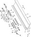
图1是本发明具润滑导管的滑台装置实施例的立体组图;1 is a three-dimensional assembly view of an embodiment of a slide table device with a lubricating conduit according to the present invention;
图2是该实施例的立体分解图;Figure 2 is an exploded perspective view of this embodiment;
图3是该实施例不完整的立体分解图,说明一个润滑导管及一对循环器;Figure 3 is a fragmentary exploded perspective view of this embodiment, illustrating a lubrication conduit and a pair of circulators;
图4是该实施例一个组合剖视图;Fig. 4 is a combined cross-sectional view of this embodiment;
图5是图4的不完整的局部放大示意图;Fig. 5 is the incomplete partial enlarged schematic diagram of Fig. 4;
图6是图5的不完整的局部放大示意图;Fig. 6 is the incomplete partial enlarged schematic diagram of Fig. 5;
图7是沿图4中的直线Ⅵ-Ⅵ所取的剖视图。Fig. 7 is a cross-sectional view taken along line VI-VI in Fig. 4 .
具体实施方式Detailed ways
下面结合附图及实施例对本发明进行详细说明。The present invention will be described in detail below with reference to the accompanying drawings and embodiments.
参阅图1与图2,本发明具润滑导管的滑台装置的一个实施例,包含一个线性轨道10、一个滑座20、两个润滑导管30、两对循环器40、两个滚珠组50及数支螺丝60。Referring to FIGS. 1 and 2 , an embodiment of the sliding table device with lubricating conduits of the present invention includes a
该线性轨道10沿一个长轴向X延伸,并具有一对沿垂直于该长轴向X的横轴向Y呈相对设置的侧壁11、一个相交连接于所述侧壁11之间的底壁12,以及一对分别凹设于所述侧壁11内侧面且沿该长轴向X延伸的外轨槽13。The
该滑座20能沿该长轴向X滑动且套设于该线性轨道10上,并具有两个沿该长轴向X呈垂直设置的端面21、一对分别对应于所述外轨槽13且沿该长轴向X贯穿所述端面21的滚珠通孔22、数个分别设置于所述端面21且邻近于所述滚珠通孔22的螺孔23、一个连通至所述滚珠通孔22的注油通道24,以及一对与所述外轨槽13相对设置的内轨槽25,每一个滚珠通孔22分别由一个内周面221界定而成,且具有一个中段222,以及两个沿轴线L连通于该中段222的两侧且相对于该中段222呈扩孔状的扩孔部223。The sliding
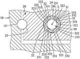
配合参图3、图5及图6,所述润滑导管30以多孔性材质制成中空管状,本实施例的润滑导管30采用高密度聚乙烯粉末热压成型。所述润滑导管30分别沿一条轴线L延伸且分别安装于所述滚珠通孔22中,每一个润滑导管30包括一个围绕该轴线L的内环面32、一个相反于该内环面32的外环面33、两个沿该轴线L呈相反设置的侧面34、两个分别由所述侧面34凹设的嵌槽35,以及一个连通该内环面32与该外环面33之间的通孔36。每一个润滑导管30的内环面32与外环面33垂直于该轴线L的截面轮廓呈非圆形,该内环面32具有数个围绕该轴线L呈间隔设置的内储油槽321,以及数个分别介于每两个内储油槽321之间的导滑部322,所述内储油槽321与所述导滑部322共同界定出一个内孔31,所述内储油槽321相对于所述导滑部322朝该外环面33凹设。每一个润滑导管30的外环面33垂直于该轴线L的截面轮廓也呈非圆形,该外环面33具有数个围绕该轴线L呈间隔设置的凸出部331,以及数个分别介于每两个凸出部331之间的圆弧部332,所述凸出部331相对于所述圆弧部332朝远离于该轴线L的外部凸出,每一个圆弧部332与相邻两个凸出部331共同界定出一个外储油槽333。该通孔36设置于其中一个凸出部331,以及与该凸出部331对应的内储油槽321之间,该通孔36连通于该注油通道24。Referring to FIG. 3 , FIG. 5 and FIG. 6 , the lubricating
配合参图3,所述循环器40分别安装于该滑座20,每一个循环器40包括一个定位于所述端面21的主体41、一个凸设于该主体41且伸设至该扩孔部223的延伸管42、一个由该主体41连通至该延伸管42的循环孔43,以及数个设置于该主体41且供所述螺丝60穿设的锁孔44。该循环孔43连通于所对应的滚珠通孔22与所对应的外轨槽13、内轨槽25之间,并具有一个设置于该主体41内部且呈U形的回弯段431,以及一个设置于该延伸管42内部且相对于该回弯段431呈扩大状的衔接段432,该回弯段431与该衔接段432衔接处产生一个肩面433,该肩面433设有一个朝该衔接段432凸设的定位块434。该衔接段432垂直于该轴线L的截面形状与所述润滑导管30的外环面33垂直于该轴线L的截面轮廓相同。每一个润滑导管30与所对应的循环器40、外轨槽13、内轨槽25共同产生一个滚珠循环通道。Referring to FIG. 3 , the
所述滚珠组50能循环运转且分别安装于由每一个润滑导管30与所对应的循环器40、外轨槽13、内轨槽25所共同产生的滚珠循环通道中。The
所述螺丝60穿过所述锁孔44且螺锁于所述螺孔23,能将所述循环器40锁固于该滑座20的所述端面21。The
为供进一步了解本发明各组件配合所产生的作用、运用技术手段,以及所预期达成的功效,将再说明如下,相信当能由此而对本发明有更深入且具体的了解。In order to further understand the functions produced by the cooperation of the various components of the present invention, the technical means used, and the expected effects, the following description will be given, and it is believed that a deeper and more specific understanding of the present invention can be obtained from this.
再如图1、图4、图5及图7所示,且配合参图3,当本发明的滑台装置整体组配完成时,利用所述循环器40以所述螺丝60锁固于该滑座20,且所述润滑导管30穿设于所述滚珠通孔22、所述衔接段432中,则利用该衔接段432垂直于该轴线L的截面形状与所述润滑导管30的外环面33垂直于该轴线L的截面轮廓相同,能使所述润滑导管30不能转动且穿设于所述滚珠通孔22与所述衔接段432中。再利用所述嵌槽35与所述定位块434的嵌接,能使所述润滑导管30沿该轴线L相对于该滑座20产生定位,且使所述通孔36对准于该注油通道24的内侧端。1 , 4 , 5 and 7 , and with reference to FIG. 3 , when the overall assembly of the sliding table device of the present invention is completed, the
当操作者自该注油通道24的外侧端注入润滑油脂时,润滑油脂会流至所述滚珠通孔22,并充填于所述外储油槽333中,且利用所述通孔36以及所述润滑导管30的多孔性材质特性,润滑油脂也会进入所述内孔31,且充填于所述内储油槽321中,润滑油脂能提供所述滚珠组50运转时的顺畅性,并延长机件的使用寿命。When the operator injects lubricating grease from the outer end of the
且本发明的所述润滑导管30,除了利用多孔性材质能储存润滑油脂外,还能利用所述内储油槽321、所述外储油槽333提供更多的储油空间,能达到长期保油及良好的润滑效果,并能减少定期保养频率,进而提升操作的整体效率。In addition, the lubricating
以下再将本发明的功效归纳说明:Below the effect of the present invention is summarized and explained again:
一、利用所述润滑导管30能避免所述滚珠组50直接接触所述滚珠通孔22的孔壁(滑座20),且避免滚珠通孔22孔径过小不容易加工、及提升该滑座20含储油量来延长该滑台装置保养周期。1. Using the lubricating
二、本发明的润滑导管30采用高密度聚乙烯粉末热压成型,所述润滑导管30借由其多孔结构而能吸收并保留油体,在所述润滑导管30吸收油体饱和时,会释放油体给通过所述润滑导管30的内孔31中的滚珠组50而达到持续润滑的效果。2. The lubricating
三、本发明的润滑导管30侧面设有通孔36,利用所述通孔36能与该注油通道24相连通,能让油体直接进入所述润滑导管30内,且借由特殊的模具加工技术,能将所述润滑导管30的剖面形状设计成非传统的真圆外型,让所述润滑导管30的外环面33上有多个外储油槽333能供填充油体,内环面32上也设有多个内储油槽321以供填充油体,而通孔36也能设计于其中一个内储油槽321处,能避免通孔36成型上的毛边影响到滚珠移动的顺畅性。3. A through
以滚珠组50的滚珠珠径4.7㎜设计为例,在相同1㎜厚度的润滑导管设计上,传统的真圆设计储油截面积约为5.609㎜2,本发明因为增加了外环面33上的外储油槽333,以及内环面32上的内储油槽321后,其截面积能增加至10.128㎜2,整体储油量提升约1.8倍。另外,在润滑导管30与滚珠组50之间产生一个空隙,能借由前述合适的空隙设计达到润滑导管30与滚珠组50之间的润滑效果优化。Taking the design of the ball diameter 4.7mm of the
本发明的循环器40具有延伸管42,对应所述延伸管42的衔接段432截面形状配合润滑导管30的外环面33截面形状,能达到限制润滑导管30旋转的效果,配合延伸管42内的定位块434与润滑导管30上的嵌槽35,组装时能确保润滑导管30上的通孔36与注油通道24相连通,且所述延伸管42也能于组装时,矫正润滑导管30、吸收滑座20的滚珠通孔22的加工误差及循环器40的装配公差,确保循环器40与润滑导管30所产生的滚珠通道顺畅无段差产生。The
综上所述,本发明的润滑导管30形状、结构简单,且安装于该滑台装置内部时,能提供滚珠组50润滑且产生较佳的运转顺畅性,且使该滑台装置具有长期保油的功效及良好的润滑效果,能减少定期保养频率,进而提升整体的移动效率并延长组件的使用寿命,确实能达成本发明的目的。To sum up, the lubricating
Claims (8)
Translated fromChineseApplications Claiming Priority (2)
| Application Number | Priority Date | Filing Date | Title |
|---|---|---|---|
| TW108135547 | 2019-10-01 | ||
| TW108135547ATWI691655B (en) | 2019-10-01 | 2019-10-01 | Lubrication duct and sliding table device with lubrication duct |
Publications (2)
| Publication Number | Publication Date |
|---|---|
| CN112594283A CN112594283A (en) | 2021-04-02 |
| CN112594283Btrue CN112594283B (en) | 2022-04-29 |
Family
ID=71134419
Family Applications (1)
| Application Number | Title | Priority Date | Filing Date |
|---|---|---|---|
| CN202010003772.6AActiveCN112594283B (en) | 2019-10-01 | 2020-01-03 | Lubrication ducts and slide units with lubrication ducts |
Country Status (5)
| Country | Link |
|---|---|
| US (1) | US11067125B2 (en) |
| JP (1) | JP6993008B2 (en) |
| KR (1) | KR102346452B1 (en) |
| CN (1) | CN112594283B (en) |
| TW (1) | TWI691655B (en) |
Families Citing this family (7)
| Publication number | Priority date | Publication date | Assignee | Title |
|---|---|---|---|---|
| KR20220060244A (en)* | 2020-11-04 | 2022-05-11 | 현대자동차주식회사 | Seat rail for vehicle |
| TWI769806B (en)* | 2021-05-03 | 2022-07-01 | 東佑達自動化科技股份有限公司 | Compound screw slide table |
| CN116181797A (en)* | 2021-11-29 | 2023-05-30 | 银泰科技股份有限公司 | Linear slide rail and guide rail lubricating structure thereof |
| CN116181796A (en)* | 2021-11-29 | 2023-05-30 | 银泰科技股份有限公司 | Linear slide rail and chain belt lubricating structure thereof |
| TWI812405B (en)* | 2022-08-16 | 2023-08-11 | 東佑達自動化科技股份有限公司 | slide device |
| WO2024154341A1 (en)* | 2023-01-20 | 2024-07-25 | 黒田精工株式会社 | Ball screw actuator |
| WO2024154340A1 (en)* | 2023-01-20 | 2024-07-25 | 黒田精工株式会社 | Ball screw actuator |
Citations (3)
| Publication number | Priority date | Publication date | Assignee | Title |
|---|---|---|---|---|
| US5299465A (en)* | 1991-09-25 | 1994-04-05 | Nsk Ltd. | Ball screw integrated type linear movement guiding unit |
| TW200925450A (en)* | 2007-09-27 | 2009-06-16 | Thk Co Ltd | Linear guide device |
| CN202867560U (en)* | 2012-09-28 | 2013-04-10 | 全球传动科技股份有限公司 | Ball spline set and its outer cylinder |
Family Cites Families (22)
| Publication number | Priority date | Publication date | Assignee | Title |
|---|---|---|---|---|
| JPH10205534A (en)* | 1997-01-17 | 1998-08-04 | Nippon Thompson Co Ltd | Linear motion guide unit with lubrication plate |
| DE19851995B4 (en)* | 1997-11-11 | 2006-01-12 | Nsk Ltd. | Continuously adjustable toroidal transmission |
| JP4502290B2 (en)* | 1999-09-10 | 2010-07-14 | 日本トムソン株式会社 | Linear motion rolling guide unit |
| US6712511B2 (en)* | 2001-02-21 | 2004-03-30 | Nippon Thompson Co., Ltd. | Linear motion guide unit |
| DE60108063T2 (en)* | 2001-02-23 | 2005-12-15 | Nippon Thompson Co. Ltd. | Linear guide unit |
| DE102004018820A1 (en)* | 2004-04-19 | 2005-11-03 | Rexroth Star Gmbh | Linear guide device and method for its production |
| DE602005007678D1 (en)* | 2004-11-11 | 2008-08-07 | Nsk Ltd | Linear roller bearing and Wälzkörperkette for it |
| JP2006220276A (en)* | 2005-02-14 | 2006-08-24 | Nsk Ltd | Separator for linear motion guide device and linear motion guide device |
| DE102006012623A1 (en)* | 2006-03-20 | 2007-09-27 | Schaeffler Kg | A roller chain |
| DE102009009011B4 (en)* | 2009-02-16 | 2023-02-02 | Robert Bosch Gmbh | Linear motion device with partially supported rolling surface part |
| WO2010137755A1 (en)* | 2009-05-28 | 2010-12-02 | (주)팜코 | Adjustable preload type linear guide system |
| TWM379483U (en)* | 2009-12-25 | 2010-05-01 | Hiwin Mikrosystem Corp | Platform with automatic lubrication mechanism |
| TWM387174U (en)* | 2010-04-02 | 2010-08-21 | Goldtech Motion Technology Co Ltd | Linear motion module |
| TWM404292U (en)* | 2010-12-22 | 2011-05-21 | Tbi Motion Technology Co Ltd | Linear motion module with self-lubricating function |
| CN201902448U (en)* | 2010-12-28 | 2011-07-20 | 全球传动科技股份有限公司 | Linear motion module with self-lubricating function |
| US9337703B2 (en)* | 2011-06-08 | 2016-05-10 | Johnson Electric S.A. | Thrust bearing assembly |
| JP3173993U (en) | 2011-12-19 | 2012-03-01 | 日本特殊ベアリング株式会社 | Ball spline with lubrication mechanism |
| TWI503489B (en)* | 2012-05-23 | 2015-10-11 | Chieftech Prec Co Ltd | Circulation maintaining device and its half mediate plates for linear slide assembly |
| US9163665B2 (en)* | 2013-09-27 | 2015-10-20 | Ome Technology Co., Ltd. | Linear guideway |
| CN106415070A (en)* | 2013-11-25 | 2017-02-15 | 斯凯孚公司 | Linear Electromechanical Actuator |
| JP6716231B2 (en)* | 2015-11-11 | 2020-07-01 | 日本トムソン株式会社 | Bending rolling guide unit |
| CN206785869U (en)* | 2017-06-14 | 2017-12-22 | 丽水市远锦传动科技有限公司 | A kind of straight-line guide rail slide block |
- 2019
- 2019-10-01TWTW108135547Apatent/TWI691655B/enactive
- 2020
- 2020-01-03CNCN202010003772.6Apatent/CN112594283B/enactiveActive
- 2020-01-22USUS16/749,379patent/US11067125B2/enactiveActive
- 2020-02-07JPJP2020019433Apatent/JP6993008B2/enactiveActive
- 2020-03-13KRKR1020200031191Apatent/KR102346452B1/enactiveActive
Patent Citations (3)
| Publication number | Priority date | Publication date | Assignee | Title |
|---|---|---|---|---|
| US5299465A (en)* | 1991-09-25 | 1994-04-05 | Nsk Ltd. | Ball screw integrated type linear movement guiding unit |
| TW200925450A (en)* | 2007-09-27 | 2009-06-16 | Thk Co Ltd | Linear guide device |
| CN202867560U (en)* | 2012-09-28 | 2013-04-10 | 全球传动科技股份有限公司 | Ball spline set and its outer cylinder |
Also Published As
| Publication number | Publication date |
|---|---|
| CN112594283A (en) | 2021-04-02 |
| JP2021055827A (en) | 2021-04-08 |
| TW202115325A (en) | 2021-04-16 |
| US11067125B2 (en) | 2021-07-20 |
| US20210095718A1 (en) | 2021-04-01 |
| TWI691655B (en) | 2020-04-21 |
| KR20210039912A (en) | 2021-04-12 |
| KR102346452B1 (en) | 2021-12-31 |
| JP6993008B2 (en) | 2022-01-13 |
Similar Documents
| Publication | Publication Date | Title |
|---|---|---|
| CN112594283B (en) | Lubrication ducts and slide units with lubrication ducts | |
| JP4584888B2 (en) | Linear motion guidance unit | |
| US20090304312A1 (en) | Motion guide device and attachment for motion guide device | |
| CN210461397U (en) | Self-lubricating type linear guide rail sliding block pair | |
| JP4340617B2 (en) | Linear motion guidance unit | |
| JP4797107B2 (en) | Motion guide device and manufacturing method thereof | |
| KR100940381B1 (en) | Rolling guide device and manufacturing method thereof | |
| JP4469705B2 (en) | Linear motion guidance unit | |
| CN216812527U (en) | Rolling linear guide rail pair with integrated ball circulation retaining structure | |
| US20170130771A1 (en) | Curvilinear motion rolling guide unit | |
| JP2007092800A (en) | Linear motion guidance unit | |
| CN109531409A (en) | Compound micro- texture guide rail of one kind and preparation method thereof | |
| WO2015068653A1 (en) | Roller bearing guide device | |
| CN108506340A (en) | Noise reduction sliding block and line slideway auxiliary | |
| JP2007285359A (en) | Linear guide device and linear guide assembly using the same | |
| CN113864332B (en) | Rolling linear guide rail pair with integrated ball circulation retaining structure | |
| CN217234129U (en) | Symmetrical split type reverser for roller guide rail pair | |
| CN109226713A (en) | Core-pulling slide block antifriction guide frame | |
| CN223441642U (en) | Hydrostatic guideway device | |
| JP6439333B2 (en) | Rolling bearing guide device | |
| JP4634223B2 (en) | Linear motion guidance unit | |
| CN219932731U (en) | Self-lubricating linear guide rail | |
| CN220320100U (en) | Roller slideway structure and sliding block | |
| JP2014196811A (en) | Lubricant supply mechanism for linear guide, linear guide including the same, and lubricant supply method for linear guide | |
| JP2014181724A (en) | Linear motion guide unit including oil storage plate |
Legal Events
| Date | Code | Title | Description |
|---|---|---|---|
| PB01 | Publication | ||
| PB01 | Publication | ||
| SE01 | Entry into force of request for substantive examination | ||
| SE01 | Entry into force of request for substantive examination | ||
| GR01 | Patent grant | ||
| GR01 | Patent grant |