CN112589264B - Segmented defocusing laser polishing method for turbine guide vane of oxygen generator - Google Patents
Segmented defocusing laser polishing method for turbine guide vane of oxygen generatorDownload PDFInfo
- Publication number
- CN112589264B CN112589264BCN202011458804.8ACN202011458804ACN112589264BCN 112589264 BCN112589264 BCN 112589264BCN 202011458804 ACN202011458804 ACN 202011458804ACN 112589264 BCN112589264 BCN 112589264B
- Authority
- CN
- China
- Prior art keywords
- polishing
- laser
- guide vane
- turbine guide
- scanning
- Prior art date
- Legal status (The legal status is an assumption and is not a legal conclusion. Google has not performed a legal analysis and makes no representation as to the accuracy of the status listed.)
- Active
Links
Images


Classifications
- B—PERFORMING OPERATIONS; TRANSPORTING
- B23—MACHINE TOOLS; METAL-WORKING NOT OTHERWISE PROVIDED FOR
- B23K—SOLDERING OR UNSOLDERING; WELDING; CLADDING OR PLATING BY SOLDERING OR WELDING; CUTTING BY APPLYING HEAT LOCALLY, e.g. FLAME CUTTING; WORKING BY LASER BEAM
- B23K26/00—Working by laser beam, e.g. welding, cutting or boring
- B23K26/352—Working by laser beam, e.g. welding, cutting or boring for surface treatment
- B23K26/3568—Modifying rugosity
- B23K26/3576—Diminishing rugosity, e.g. grinding; Polishing; Smoothing
- B—PERFORMING OPERATIONS; TRANSPORTING
- B23—MACHINE TOOLS; METAL-WORKING NOT OTHERWISE PROVIDED FOR
- B23K—SOLDERING OR UNSOLDERING; WELDING; CLADDING OR PLATING BY SOLDERING OR WELDING; CUTTING BY APPLYING HEAT LOCALLY, e.g. FLAME CUTTING; WORKING BY LASER BEAM
- B23K26/00—Working by laser beam, e.g. welding, cutting or boring
- B23K26/12—Working by laser beam, e.g. welding, cutting or boring in a special atmosphere, e.g. in an enclosure
- B—PERFORMING OPERATIONS; TRANSPORTING
- B23—MACHINE TOOLS; METAL-WORKING NOT OTHERWISE PROVIDED FOR
- B23K—SOLDERING OR UNSOLDERING; WELDING; CLADDING OR PLATING BY SOLDERING OR WELDING; CUTTING BY APPLYING HEAT LOCALLY, e.g. FLAME CUTTING; WORKING BY LASER BEAM
- B23K26/00—Working by laser beam, e.g. welding, cutting or boring
- B23K26/60—Preliminary treatment
Landscapes
- Engineering & Computer Science (AREA)
- Physics & Mathematics (AREA)
- Optics & Photonics (AREA)
- Plasma & Fusion (AREA)
- Mechanical Engineering (AREA)
- Laser Beam Processing (AREA)
- Electrical Discharge Machining, Electrochemical Machining, And Combined Machining (AREA)
Abstract
Translated fromChinese
Description
Translated fromChinese技术领域technical field
本发明涉及一种针对制氧机透平导叶的分段离焦激光抛光方法。The invention relates to a segmented defocusing laser polishing method for an oxygen generator turbine guide vane.
背景技术Background technique
激光抛光是一种新型激光加工技术,它通过一个聚焦的激光束斑作用在粗糙的原始金属表面,使金属材料表面凸起薄层产生熔化和蒸发现象,并由于材料本身的表面张力和重力的作用而发生流动,填补金属表面凹陷处并发生凝固,最终得到理想的抛光材料表面。由于激光抛光只在微米厚度的材料层上发生作用,因而相对一般的激光束加工金属具有更高的加工精度。其具有环境污染小、抛光精度高、抛光材料范围广泛、微小区域抛光等传统抛光无法比拟的优点。Laser polishing is a new type of laser processing technology. It acts on the rough original metal surface through a focused laser beam spot, so that the convex thin layer on the surface of the metal material melts and evaporates, and due to the surface tension and gravity of the material itself. It flows, fills the depressions on the metal surface and solidifies, and finally obtains the ideal surface of the polishing material. Since laser polishing only works on a material layer with a thickness of micrometers, it has higher machining accuracy than ordinary laser beam machining of metals. It has the incomparable advantages of traditional polishing, such as less environmental pollution, high polishing precision, wide range of polishing materials, and small area polishing.
透平导叶是制氧机的膨胀机中调节气流量的主要构件,由于其不规则的形状结构,目前只能采用电火花线切割的方式切制成型。但线切割表面因电火花的瞬时高温腐蚀而具有较大的表面粗糙度(Ra≈4μm),导致导叶间气流流通的能力和效率下降。此外,在长期服役过程中,由于不可避免的有杂质异物混入流动空气中,久而久之导叶表面会积垢和腐蚀,亦使表面粗糙度增加。为降低导叶表面粗糙度并提升制氧机运行效率,需对透平导叶表面进行抛光处理。The turbine guide vane is the main component for adjusting the airflow in the expander of the oxygen generator. Due to its irregular shape and structure, it can only be cut and formed by wire EDM. However, the wire-cut surface has a large surface roughness (Ra≈4μm) due to the instantaneous high-temperature corrosion of the electric spark, which leads to a decrease in the ability and efficiency of airflow between the guide vanes. In addition, in the long-term service process, due to the inevitable mixing of impurities and foreign matter into the flowing air, the surface of the guide vane will be fouled and corroded over time, and the surface roughness will also increase. In order to reduce the surface roughness of the guide vane and improve the operation efficiency of the oxygen generator, the surface of the turbine guide vane needs to be polished.
目前,对透平导叶粗糙表面的抛光主要以传统抛光方式(手工抛光、化学、电化学抛光)为主。手工抛光方式存在无法精确打磨不规则表面,手工打磨工作强度大等两个主要问题。而化学、电化学抛光的方式,会对环境造成污染,且两者的抛光效率均太低。而激光抛光不规则曲面,传统思路是给激光抛光系统配备三维振镜和多轴机械手来处理,但会提升成本且使控制系统复杂。At present, traditional polishing methods (manual polishing, chemical polishing, electrochemical polishing) are mainly used for polishing the rough surface of the turbine guide vane. The manual polishing method has two main problems, such as the inability to precisely polish the irregular surface and the high intensity of manual polishing. The chemical and electrochemical polishing methods will pollute the environment, and the polishing efficiency of both is too low. For laser polishing irregular surfaces, the traditional idea is to equip the laser polishing system with a three-dimensional galvanometer and a multi-axis manipulator to process, but it will increase the cost and complicate the control system.
发明内容SUMMARY OF THE INVENTION
为了克服现有制氧机透平导叶的传统抛光技术中存在的缺陷,以及抛光曲面带来的设备成本提高问题,本发明提供了一种针对制氧机透平导叶的分段离焦激光抛光方法。采用激光抛光的方式对透平导叶粗糙表面进行高效抛光,利用激光抛光设备不同离焦量下具有相同的抛光效果的特点来对透平导叶不规则粗糙表面进行分段离焦抛光。In order to overcome the defects existing in the traditional polishing technology of the turbine guide vane of the oxygen generator and the problem of increasing equipment cost caused by the polished curved surface, the present invention provides a segmented defocusing method for the turbine guide vane of the oxygen generator. Laser polishing method. The rough surface of the turbine guide vane is efficiently polished by laser polishing, and the irregular rough surface of the turbine guide vane is subjected to segmental defocus polishing by using the feature that the laser polishing equipment has the same polishing effect under different defocus amounts.
本发明的技术方案如下:The technical scheme of the present invention is as follows:
一种针对制氧机透平导叶的分段离焦激光抛光方法,包括如下步骤:A segmented defocusing laser polishing method for an oxygen generator turbine guide vane, comprising the following steps:
(1)将透平导叶待抛光侧表面进行清洗、干燥预处理,然后放置并固定在顶端安装有激光透镜的气氛保护箱内,激光头设置在气氛保护箱上方;(1) The surface of the turbine guide vane to be polished is cleaned, dried and pretreated, and then placed and fixed in an atmosphere protection box with a laser lens installed at the top, and the laser head is arranged above the atmosphere protection box;
所述透平导叶的材料为不锈钢,如304、316L等;The material of the turbine guide vane is stainless steel, such as 304, 316L, etc.;
所述气氛保护箱内持续通入氩气,氩气的气流量为5~30L/min;Argon gas is continuously introduced into the atmosphere protection box, and the gas flow rate of argon gas is 5-30 L/min;
所述激光透镜能透过波长193~1064nm的激光束;The laser lens can transmit a laser beam with a wavelength of 193-1064 nm;
(2)根据激光抛光设备相同抛光效果下的离焦量范围,结合不同型号导叶的外形尺寸,对透平导叶待抛光侧面进行分段,确定抛光扫描区域的位置及尺寸;(2) According to the range of the defocus amount under the same polishing effect of the laser polishing equipment, combined with the external dimensions of the guide vanes of different types, segment the sides of the turbine guide vanes to be polished to determine the location and size of the polishing scanning area;
所述扫描区域为长度5~80mm,宽度5~30mm尺寸范围内的矩形区域,扫描区域长度和宽度均多出待抛光侧面边缘1mm,确保覆盖待抛光侧面;The scanning area is a rectangular area with a length of 5-80 mm and a width of 5-30 mm, and the length and width of the scanning area are 1 mm longer than the edge of the side to be polished to ensure that the side to be polished is covered;
(3)设定激光抛光设备的激光功率,扫描速度,开关光延迟时间,扫描区域填充方式,填充线间距;(3) Set the laser power, scanning speed, switching light delay time, scanning area filling method and filling line spacing of the laser polishing equipment;
所述激光功率为100~300W,扫描速度为100~500mm/s,扫描区域填充方式为横向扫描、纵向叠加,填充线间距为0.02~0.05mm;The laser power is 100-300W, the scanning speed is 100-500mm/s, the scanning area filling mode is horizontal scanning and vertical stacking, and the filling line spacing is 0.02-0.05mm;
为确保扫描区域与区域间搭接区的质量,以扫描速度为v,开关光延迟时间为T,而扫描振镜加速度为a,则振镜摆动稳定时间为t=v/a,开关光延迟时间的设定为T=t=v/a,所述搭接区的宽度范围为1~2mm;In order to ensure the quality of the overlap area between the scanning area and the area, the scanning speed is v, the switching light delay time is T, and the scanning galvanometer acceleration is a, then the galvanometer swing stabilization time is t=v/a, and the switching light delay is t=v/a. The time is set as T=t=v/a, and the width of the overlapping area ranges from 1 to 2 mm;
(4)开启激光器,激光束依次对设定的扫描区域进行抛光;(4) Turn on the laser, and the laser beam polishes the set scanning area in turn;
所述扫描区域的抛光次数为1~4次,每后一次扫描均与前一次扫描成正交方向,以达到更好的抛光效果;The number of polishing times in the scanning area is 1 to 4 times, and each subsequent scan is in an orthogonal direction to the previous scan, so as to achieve a better polishing effect;
(5)停止激光器,完成对透平导叶不规则粗糙侧面的全覆盖激光抛光。(5) Stop the laser, and complete the full-coverage laser polishing of the irregular rough sides of the turbine guide vanes.
本发明采用激光加热透平导叶表面材料,使粗糙的薄层凸起材料产生熔化流动现象,填补金属表面凹陷处并凝固,最终获得平坦的抛光表面。所述透平导叶放置于气氛保护箱中,往保护箱中持续通入氩气,以防止激光抛光过程中所述透平导叶表面氧化。激光光斑尺寸通过聚焦场镜聚焦后达100~200μm,能实现透平导叶表面高精度的精细加工。在100~300W激光功率和100~500mm/s扫描速度条件下,透平导叶粗糙表面材料快速熔化凝固,重熔层深度浅,对基体材料性能不产生影响。对扫描区域的抛光次数可增加,以达到更好的抛光效果。The invention adopts the laser to heat the surface material of the turbine guide vane, so that the rough thin-layer convex material produces the phenomenon of melting and flowing, fills the depression on the metal surface and solidifies, and finally obtains a flat polished surface. The turbine guide vane is placed in an atmosphere protection box, and argon gas is continuously introduced into the protection box to prevent the surface of the turbine guide vane from being oxidized during the laser polishing process. The size of the laser spot can reach 100-200μm after being focused by the focusing field lens, which can realize the high-precision fine processing of the surface of the turbine guide vane. Under the conditions of 100-300W laser power and 100-500mm/s scanning speed, the rough surface material of the turbine guide vane melts and solidifies rapidly, and the depth of the remelting layer is shallow, which does not affect the performance of the matrix material. The number of polishing times on the scanned area can be increased to achieve better polishing results.
本发明的有益效果在于:The beneficial effects of the present invention are:
本发明将激光抛光技术应用于制氧机透平导叶的抛光,利用激光作用效率高,聚焦光斑小从而加工精度高及其具有一定焦深范围的优点,可以实现透平导叶不规则粗糙表面的高效率抛光,该方法工艺过程简单,相对现有透平导叶不规则粗糙表面传统抛光方法具有极大的优势;The invention applies the laser polishing technology to the polishing of the turbine guide vane of the oxygen generator, and the laser has the advantages of high action efficiency, small focusing spot, high processing precision, and a certain focal depth range, and can realize irregular roughness of the turbine guide vane. High-efficiency polishing of the surface, the method has a simple process, and has great advantages compared with the traditional polishing method of the irregular rough surface of the turbine guide vane;
本发明只在微米厚度的材料层上发生重熔作用平复粗糙表面,因而相对具宏观尺寸光斑大小的激光束加工金属而言,对基体材料的影响很小;In the present invention, the remelting effect only occurs on the material layer with a thickness of micrometers to smooth the rough surface, so compared with the laser beam processing metal with a macro-sized spot size, the influence on the base material is very small;
本发明利用激光抛光设备不同离焦量范围具有相同抛光效果的特点,通过离焦的方式,使得在离焦量范围内的透平导叶侧面粗糙部分能被有效的抛光;The present invention utilizes the feature that the laser polishing equipment has the same polishing effect in different defocus amount ranges, and enables the rough part of the side surface of the turbine guide vane within the defocus amount range to be effectively polished by means of defocusing;
本发明根据激光抛光设备的离焦量范围以及透平导叶的尺寸形状,对其待抛光侧面进行分段,在具有相同抛光效果的离焦量范围内,通过对不同分段进行激光抛光,使得导叶不规则表面能实现全覆盖抛光;According to the defocus amount range of the laser polishing equipment and the size and shape of the turbine guide vane, the invention divides the side surface to be polished into segments, and within the defocus amount range with the same polishing effect, by laser polishing different segments, The irregular surface of the guide vane can be fully covered and polished;
本发明避免了为抛光不规则曲面而引入机械手和三维振镜而带来的超高的成本和控制系统复杂的问题。The invention avoids the problems of super high cost and complicated control system brought by introducing a manipulator and a three-dimensional galvanometer for polishing irregular curved surfaces.
附图说明Description of drawings
图1是实施例1中导叶抛光前实物图。FIG. 1 is a real picture of the guide vane in Example 1 before polishing.
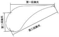
图2是实施例1中导叶待抛光区域划分示意图。FIG. 2 is a schematic diagram of the division of the to-be-polished area of the guide vane in Example 1. FIG.
图3是实施例1中导叶抛光后实物图。FIG. 3 is a physical view of the guide vane in Example 1 after polishing.
图4是实施例1中抛光后导叶的重熔层厚度金相图。4 is a metallographic diagram of the thickness of the remelted layer of the guide vane after polishing in Example 1.
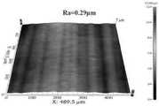
图5是实施例1中抛光后导叶的表面三维轮廓扫描图。FIG. 5 is a three-dimensional profile scanning diagram of the surface of the guide vane after polishing in Example 1. FIG.
具体实施方式Detailed ways
下面通过具体实施例对本发明作进一步的说明,但本发明的保护范围并不仅限于此。The present invention will be further described below through specific embodiments, but the protection scope of the present invention is not limited thereto.
实施例1Example 1
选取制氧机中的不锈钢透平导叶,其形状如图1所示,长宽尺寸为52mm×28mm,厚度为12mm,将粗糙表面做清洗、干燥等预处理。Select the stainless steel turbine guide vane in the oxygen generator, its shape is shown in Figure 1, the length and width are 52mm × 28mm, and the thickness is 12mm, and the rough surface is cleaned and dried.
根据激光器相同抛光效果的离焦量范围为-5~+5mm,以及透平导叶尺寸外形,将导叶粗糙表面划分为3块待抛光区域,扫描区域大小分别为14×45mm,14×25mm和14×65mm,扫描区域的长度和宽度均多出待抛光侧面边缘1mm,确保覆盖待抛光侧面,每块划分的区域与区域之间存在宽度为1mm的搭接区,划分示意图如图2所示。将导叶第一块待抛光区域朝上放置于气氛保护箱内,并对其进行固定。According to the defocus range of the same polishing effect of the laser is -5~+5mm, and the size and shape of the turbine guide vane, the rough surface of the guide vane is divided into 3 areas to be polished, and the scanning area sizes are 14×45mm and 14×25mm respectively. and 14×65mm, the length and width of the scanning area are 1mm longer than the edge of the side to be polished to ensure that the side to be polished is covered, and there is a lap area with a width of 1mm between each divided area. The schematic diagram of the division is shown in Figure 2. Show. Place the first area of the guide vane to be polished upwards in the atmosphere protection box and fix it.
设置激光功率为250W,扫描速度为300mm/s,开光关光延迟时间分别为-1000μs和+1000μs,填充方式为直线横向扫描、纵向叠加,填充线间距为0.02mm,保护气为氩气,保护气流量为15L/min。Set the laser power to 250W, the scanning speed to 300mm/s, the delay time of turning on and off the light to -1000μs and +1000μs respectively, the filling method is linear horizontal scanning, vertical stacking, the filling line spacing is 0.02mm, the protective gas is argon, and the protective gas is argon. Air flow is 15L/min.
开启激光器,对第一段导叶待抛光区域进行扫描。Turn on the laser and scan the to-be-polished area of the first guide vane.
扫描结束后,将导叶的第二块待抛光区域朝上放置于气氛保护箱内并固定,开启激光器,对第二段待抛光区域进行扫描。After scanning, place the second to-be-polished area of the guide vane upward in the atmosphere protection box and fix it, turn on the laser, and scan the second to-be-polished area.
依次类推,直至完成对导叶不规则粗糙表面的全覆盖激光抛光,抛光后导叶表面无氧化现象,呈现出金属光泽和镜面效果,表面形貌良好,抛光后导叶如图3所示。By analogy, until the laser polishing of the irregular rough surface of the guide vane is completed, the surface of the guide vane has no oxidation phenomenon after polishing, showing metallic luster and mirror effect, and the surface morphology is good. The guide vane after polishing is shown in Figure 3.
用线切割切取抛光后的导叶试样截面,做金相分析,抛光后导叶截面金相如图4所示,重熔层厚度仅为105.31μm。激光抛光只是对表面的浅熔,不影响基体性能。The polished guide vane sample section was cut by wire cutting for metallographic analysis. The metallographic phase of the polished guide vane section is shown in Figure 4, and the thickness of the remelted layer is only 105.31 μm. Laser polishing is only a shallow melting of the surface and does not affect the performance of the substrate.
用白光干涉仪对抛光表面做粗糙度分析,其激光抛光表面三维轮廓形貌如图5所示,粗糙度值为Ra=0.29μm。The roughness of the polished surface was analyzed with a white light interferometer. The three-dimensional profile of the laser polished surface is shown in Figure 5, and the roughness value is Ra=0.29 μm.
本发明针对现有制氧机透平导叶抛光技术中存在的问题,提出利用激光对透平导叶粗糙表面进行重熔处理,以达到表面激光抛光的目的。此方法将激光作为热源,利用激光抛光设备具有一定焦深范围的特点来对透平导叶粗糙表面进行分段重熔处理,使微观凸起材料熔化流动填充凹陷,并对整个过程进行惰性气体保护,实现导叶不规则粗糙表面抛光。本发明可实现透平导叶不规则表面的全覆盖抛光,避免传统抛光方式为抛光不规则曲面而引入机械手、三维振镜设备带来的高成本问题,且激光抛光效率高,工艺简单,整个抛光过程可靠易操作。Aiming at the problems existing in the existing oxygen generator turbine guide vane polishing technology, the invention proposes to use laser to remelt the rough surface of the turbine guide vane, so as to achieve the purpose of surface laser polishing. In this method, the laser is used as the heat source, and the rough surface of the turbine guide vane is remelted in stages by using the characteristics of the laser polishing equipment with a certain focal depth range, so that the microscopic convex materials are melted and flowed to fill the depressions, and the whole process is treated with an inert gas. Protection, to achieve irregular rough surface polishing of guide vanes. The invention can realize the full coverage polishing of the irregular surface of the turbine guide vane, avoid the high cost problem caused by the introduction of manipulators and three-dimensional galvanometer equipment in the traditional polishing method for polishing irregular curved surfaces, and has high laser polishing efficiency and simple process. The polishing process is reliable and easy to operate.
本说明书实施例所述的内容仅仅是对发明构思的实现形式的例举,本发明的保护范围不应当被视为仅限于实施例陈述的具体形式,本发明的保护范围也及于本领域技术人员根据本发明构思所能够想到的等同技术手段。The contents described in the embodiments of this specification are only examples of the realization forms of the inventive concept, and the protection scope of the present invention should not be regarded as limited to the specific forms stated in the embodiments, and the protection scope of the present invention also extends to those skilled in the art. Equivalent technical means that can be conceived by a person based on the inventive concept.
Claims (4)
Priority Applications (1)
| Application Number | Priority Date | Filing Date | Title |
|---|---|---|---|
| CN202011458804.8ACN112589264B (en) | 2020-12-11 | 2020-12-11 | Segmented defocusing laser polishing method for turbine guide vane of oxygen generator |
Applications Claiming Priority (1)
| Application Number | Priority Date | Filing Date | Title |
|---|---|---|---|
| CN202011458804.8ACN112589264B (en) | 2020-12-11 | 2020-12-11 | Segmented defocusing laser polishing method for turbine guide vane of oxygen generator |
Publications (2)
| Publication Number | Publication Date |
|---|---|
| CN112589264A CN112589264A (en) | 2021-04-02 |
| CN112589264Btrue CN112589264B (en) | 2022-10-11 |
Family
ID=75192965
Family Applications (1)
| Application Number | Title | Priority Date | Filing Date |
|---|---|---|---|
| CN202011458804.8AActiveCN112589264B (en) | 2020-12-11 | 2020-12-11 | Segmented defocusing laser polishing method for turbine guide vane of oxygen generator |
Country Status (1)
| Country | Link |
|---|---|
| CN (1) | CN112589264B (en) |
Families Citing this family (1)
| Publication number | Priority date | Publication date | Assignee | Title |
|---|---|---|---|---|
| CN113601018A (en)* | 2021-07-08 | 2021-11-05 | 深圳信息职业技术学院 | Laser polishing method and laser polishing equipment |
Family Cites Families (7)
| Publication number | Priority date | Publication date | Assignee | Title |
|---|---|---|---|---|
| GB201500304D0 (en)* | 2015-01-09 | 2015-02-25 | Rolls Royce Plc | A method of surface-treating a cast intermetallic component |
| CN107225328A (en)* | 2017-04-14 | 2017-10-03 | 北京航空航天大学 | A kind of single step pulse laser polishing method for metal surface |
| CN109759711B (en)* | 2017-11-09 | 2021-09-14 | 香港理工大学 | Laser polishing method |
| CN108326432A (en)* | 2018-03-08 | 2018-07-27 | 北京工业大学 | A kind of laser polishing device and method of SLM moldings TC4 alloys |
| CN111041475B (en)* | 2019-12-25 | 2022-01-14 | 浙江工业大学 | Method for preparing reinforced coating by laser alloying/polishing composite integration |
| CN111113162B (en)* | 2020-01-10 | 2021-04-30 | 华侨大学 | Robot-based planning and polishing method for special-shaped stone curved surface |
| CN111390392A (en)* | 2020-04-03 | 2020-07-10 | 北京航空航天大学 | A laser processing technology for polishing semiconductor materials |
- 2020
- 2020-12-11CNCN202011458804.8Apatent/CN112589264B/enactiveActive
Also Published As
| Publication number | Publication date |
|---|---|
| CN112589264A (en) | 2021-04-02 |
Similar Documents
| Publication | Publication Date | Title |
|---|---|---|
| CN109773340B (en) | A laser cleaning and polishing composite processing method for carbon steel surface | |
| US7411150B2 (en) | Method of producing a composite component | |
| CN108405486B (en) | Laser cleaning device and laser cleaning method | |
| CN206298642U (en) | It is a kind of that the laser cladding equipment for preheating gentle cold light is produced based on bifocal | |
| CN109207905B (en) | Method and device for preparing titanium alloy blade anti-corrosion layer based on laser nitriding partition based on scanning galvanometer | |
| CN114571086B (en) | Nanosecond laser-induced plasma composite femtosecond laser processing device and processing method | |
| CN207521870U (en) | Laser output system based on homogenizer | |
| CN114131208B (en) | Laser-induced plasma profiling device and method | |
| CN109108485B (en) | A method for repairing complex-structure alumina ceramic cores using picosecond lasers | |
| CN108500468A (en) | A kind of method of curved profile laser deburring | |
| CN112589264B (en) | Segmented defocusing laser polishing method for turbine guide vane of oxygen generator | |
| CN110614440A (en) | CO2 laser remelting and gasification composite polishing method for optical element | |
| CN108499984A (en) | A kind of laser cleaning method of Process on Aluminum Alloy Oxidation Film | |
| CN111571004A (en) | Laser processing ductile iron material surface composite microtexture method and processing system | |
| CN115570271A (en) | A Method for Oblique Polishing of Silicon Carbide Ceramics Based on High Repetition Frequency Femtosecond Laser | |
| CN115446455B (en) | Corner laser welding method based on power follow-up control | |
| CN104625432B (en) | The laser cutting method of a kind of wolfram steel thin slice and system | |
| CN110549016A (en) | Femtosecond laser cutting method for silicon carbide | |
| CN114669882A (en) | Infrared ultrafast laser diamond cutter head repair method and system | |
| CN103028798A (en) | Method and system for continuous laser electrochemical metal micro-forming processing | |
| CN102649194B (en) | A kind of laser processing of optics blind spot and laser processing device | |
| CN118808912A (en) | A method and system for laser spot welding of dissimilar materials | |
| CN100379515C (en) | Composite element, method for manufacturing same and turbomachine comprising same | |
| CN117600660A (en) | Copper-based metal surface multi-wavelength laser synchronous processing device and polishing method | |
| CN103801992B (en) | The rotten wet grinding processing method of engineering ceramics induced with laser |
Legal Events
| Date | Code | Title | Description |
|---|---|---|---|
| PB01 | Publication | ||
| PB01 | Publication | ||
| SE01 | Entry into force of request for substantive examination | ||
| SE01 | Entry into force of request for substantive examination | ||
| GR01 | Patent grant | ||
| GR01 | Patent grant |