CN112571796A - 3D printing forming platform capable of being leveled - Google Patents
3D printing forming platform capable of being leveledDownload PDFInfo
- Publication number
- CN112571796A CN112571796ACN202011130854.3ACN202011130854ACN112571796ACN 112571796 ACN112571796 ACN 112571796ACN 202011130854 ACN202011130854 ACN 202011130854ACN 112571796 ACN112571796 ACN 112571796A
- Authority
- CN
- China
- Prior art keywords
- wedge
- forming platform
- receiving plate
- vertical
- connecting portion
- Prior art date
- Legal status (The legal status is an assumption and is not a legal conclusion. Google has not performed a legal analysis and makes no representation as to the accuracy of the status listed.)
- Pending
Links
- 2380000101463D printingMethods0.000titleclaimsabstractdescription23
- 239000000463materialSubstances0.000claimsabstractdescription5
- 238000010586diagramMethods0.000description5
- 238000005516engineering processMethods0.000description5
- 238000004519manufacturing processMethods0.000description4
- 230000000875corresponding effectEffects0.000description2
- 238000013461designMethods0.000description2
- 230000007246mechanismEffects0.000description2
- 230000004048modificationEffects0.000description2
- 238000012986modificationMethods0.000description2
- 238000000465mouldingMethods0.000description2
- 230000001360synchronised effectEffects0.000description2
- 230000004075alterationEffects0.000description1
- 238000013459approachMethods0.000description1
- 230000009286beneficial effectEffects0.000description1
- 230000005540biological transmissionEffects0.000description1
- 230000008859changeEffects0.000description1
- 238000010276constructionMethods0.000description1
- 230000008878couplingEffects0.000description1
- 238000010168coupling processMethods0.000description1
- 238000005859coupling reactionMethods0.000description1
- 230000007812deficiencyEffects0.000description1
- 238000000034methodMethods0.000description1
- 238000007639printingMethods0.000description1
- 238000012545processingMethods0.000description1
- 238000003672processing methodMethods0.000description1
- 239000000725suspensionSubstances0.000description1
Images


Classifications
- B—PERFORMING OPERATIONS; TRANSPORTING
- B29—WORKING OF PLASTICS; WORKING OF SUBSTANCES IN A PLASTIC STATE IN GENERAL
- B29C—SHAPING OR JOINING OF PLASTICS; SHAPING OF MATERIAL IN A PLASTIC STATE, NOT OTHERWISE PROVIDED FOR; AFTER-TREATMENT OF THE SHAPED PRODUCTS, e.g. REPAIRING
- B29C64/00—Additive manufacturing, i.e. manufacturing of three-dimensional [3D] objects by additive deposition, additive agglomeration or additive layering, e.g. by 3D printing, stereolithography or selective laser sintering
- B29C64/20—Apparatus for additive manufacturing; Details thereof or accessories therefor
- B29C64/245—Platforms or substrates
- B—PERFORMING OPERATIONS; TRANSPORTING
- B33—ADDITIVE MANUFACTURING TECHNOLOGY
- B33Y—ADDITIVE MANUFACTURING, i.e. MANUFACTURING OF THREE-DIMENSIONAL [3-D] OBJECTS BY ADDITIVE DEPOSITION, ADDITIVE AGGLOMERATION OR ADDITIVE LAYERING, e.g. BY 3-D PRINTING, STEREOLITHOGRAPHY OR SELECTIVE LASER SINTERING
- B33Y30/00—Apparatus for additive manufacturing; Details thereof or accessories therefor
Landscapes
- Chemical & Material Sciences (AREA)
- Engineering & Computer Science (AREA)
- Materials Engineering (AREA)
- Manufacturing & Machinery (AREA)
- Physics & Mathematics (AREA)
- Mechanical Engineering (AREA)
- Optics & Photonics (AREA)
Abstract
Translated fromChinese
Description
Translated fromChinese技术领域technical field
本发明属于3D打印技术领域,具体涉及一种可调平的3D打印成型平台。The invention belongs to the technical field of 3D printing, and particularly relates to a flattenable 3D printing forming platform.
背景技术Background technique
3D打印作为目前一种新兴的成型技术,由于其快速成型的特点,适合制造定制化产品;3D打印通常是采用数字技术材料打印机来实现的。常在模具制造、工业设计等领域被用于制造模型,后逐渐用于一些产品的直接制造,已经有使用这种技术打印而成的零部件;该技术在珠宝、鞋类、工业设计、建筑、工程和施工、汽车,航空航天、牙科和医疗产业、教育、地理信息系统、土木工程、枪支以及其他领域都有所应用。As an emerging molding technology, 3D printing is suitable for the manufacture of customized products due to its rapid prototyping characteristics; 3D printing is usually realized by using digital technology material printers. It is often used to make models in the fields of mold making, industrial design, etc., and is gradually used in the direct manufacturing of some products. There are already parts printed using this technology; this technology is used in jewelry, footwear, industrial design, architecture, etc. , engineering and construction, automotive, aerospace, dental and medical industries, education, geographic information systems, civil engineering, firearms, and other fields.
但是,由于3D打印使用分层加工的方式进行工作,为了保证打印头逐层加工需要将打印头与成型平台保持平行,而由于3D打印机难以保证放置在水平位置处,因此,需要对3D打印机进行位置调节以满足成型平台处于水平位置处。However, since 3D printing uses a layered processing method, in order to ensure the layer-by-layer processing of the print head, the print head needs to be kept parallel to the forming platform, and because it is difficult for the 3D printer to be placed in a horizontal position, it is necessary to carry out the 3D printer. The position is adjusted so that the forming platform is in a horizontal position.
发明内容SUMMARY OF THE INVENTION
为了克服现有技术的不足,本发明提出的一种可调平的3D打印成型平台。In order to overcome the deficiencies of the prior art, the present invention proposes a flattenable 3D printing forming platform.
本发明提供的一种可调平的3D打印成型平台,包括:An adjustable 3D printing forming platform provided by the present invention includes:
成型平台,其内设置有用于承接物料的承接板以及用于调节所述承接板位置的调节模组;A forming platform is provided with a receiving plate for receiving materials and an adjustment module for adjusting the position of the receiving plate;
竖直驱动组件,用于驱动所述成型平台沿垂直水平面方向移动;其中,a vertical drive assembly for driving the forming platform to move along a vertical horizontal plane; wherein,
所述调节模组包括调节杆、楔块,通过所述调节杆调节所述楔块位置,进而带动所述承接板在垂直水平面方向上的运动,从而调节所述承接板的水平度。The adjustment module includes an adjustment rod and a wedge, and the position of the wedge is adjusted by the adjustment rod, thereby driving the movement of the receiving plate in the direction of the vertical horizontal plane, thereby adjusting the levelness of the receiving plate.
优选地,所述成型平台还包括连接部,所述连接部用于支撑所述调节模组;Preferably, the forming platform further includes a connecting portion, and the connecting portion is used to support the adjusting module;
所述竖直驱动组件驱动所述连接部,进而带动所述承接板。The vertical driving assembly drives the connecting portion, thereby driving the receiving plate.
优选地,还包括固定支架,所述固定支架用于形成所述成型平台以及所述竖直驱动组件的固定基座;Preferably, a fixing bracket is also included, and the fixing bracket is used to form the forming platform and the fixing base of the vertical driving assembly;
所述固定支架上安装用于引导所述成型平台运动方向的导向模组,通过所述导向模组与所述竖直驱动组件共同限制所述成型平台的运动轨迹。A guide module for guiding the movement direction of the forming platform is installed on the fixed bracket, and the movement track of the forming platform is jointly limited by the guide module and the vertical drive assembly.
优选地,所述竖直驱动组件包括驱动源、丝杆,所述连接部上安装有螺母座;Preferably, the vertical drive assembly includes a drive source and a screw rod, and a nut seat is mounted on the connecting portion;
通过所述丝杆与所述螺母座螺纹连接,使得所述驱动源驱使所述丝杆,从而使得所述竖直驱动组件移动。Through the screw connection of the screw rod and the nut seat, the driving source drives the screw rod to move the vertical driving assembly.
优选地,所述丝杆的数量为两个,所述丝杆设置在所述连接部的两侧;Preferably, the number of the screw rods is two, and the screw rods are arranged on both sides of the connecting portion;
所述竖直驱动组件还包括同步皮带轮,通过所述驱动源驱使所述同步皮带轮转动,进而由所述同步皮带轮带动两所述丝杆运动。The vertical drive assembly further includes a timing pulley, and the timing pulley is driven to rotate by the driving source, and then the two screw rods are driven by the timing pulley to move.
优选地,所述调节模组的数量不少于三个,所述调节模组分布设置在所述连接部靠近边缘的位置处。Preferably, the number of the adjustment modules is not less than three, and the adjustment modules are distributed and arranged at the position of the connection part close to the edge.
优选地,所述楔块包括第一楔块、第二楔块,所述第一楔块、第二楔块的斜面贴合;Preferably, the wedge block includes a first wedge block and a second wedge block, and the inclined surfaces of the first wedge block and the second wedge block fit together;
所述调节杆驱动所述第二楔块移动,所述第一楔块安装在所述承接板,通过所述调节杆驱动所述第二楔块移动以使得所述承接板沿垂直方向移动。The adjusting rod drives the second wedge to move, the first wedge is mounted on the receiving plate, and the adjusting rod drives the second wedge to move so that the receiving plate moves in the vertical direction.
优选地,所述调节模组还包括导向滑槽,所述调节杆驱动所述第二楔块,使得所述第二楔块沿所述导向滑槽方向滑动。Preferably, the adjustment module further includes a guide chute, and the adjustment rod drives the second wedge block so that the second wedge block slides along the direction of the guide chute.
优选地,所述第一楔块与所述第二楔块贴合的斜面上设置导向件,通过所述导向件引导,使得所述第二楔块相对所述第一楔块沿斜面方向移动。Preferably, a guide member is provided on the inclined surface of the first wedge block and the second wedge block, and the second wedge block is guided relative to the first wedge block in the direction of the inclined surface by being guided by the guide member .
优选地,所述导向件包括所述第二楔块上安装的滑块以及所述第一楔上开设的滑轨,通过所述滑块与所述滑轨滑动连接,使得所述第二楔块相对所述第一楔块运动。Preferably, the guide member includes a sliding block mounted on the second wedge and a sliding rail provided on the first wedge, and the sliding block is slidably connected to the sliding rail, so that the second wedge is slidably connected to the sliding rail. The block moves relative to the first wedge.
相比现有技术,本发明的有益效果在于:Compared with the prior art, the beneficial effects of the present invention are:
本发明提供的一种可调平的3D打印成型平台,通过调节杆调节楔块位置,进而带动承接板在垂直水平面方向上的运动,从而调节承接板的水平度,方便承接板保持水平,提高生产精度,本发明使用方便,结构简单。An adjustable 3D printing forming platform provided by the present invention can adjust the position of the wedge block by adjusting the rod, and then drive the movement of the receiving plate in the direction of the vertical horizontal plane, so as to adjust the levelness of the receiving plate, which is convenient for the receiving plate to maintain the level, and improves the Production accuracy, the present invention is convenient to use and simple in structure.
上述说明仅是本发明技术方案的概述,为了能够更清楚了解本发明的技术手段,并可依照说明书的内容予以实施,以下以本发明的较佳实施例并配合附图详细说明如后。本发明的具体实施方式由以下实施例及其附图详细给出。The above description is only an overview of the technical solution of the present invention. In order to understand the technical means of the present invention more clearly and implement it according to the content of the description, the following detailed description is given with the preferred embodiments of the present invention and the accompanying drawings. Specific embodiments of the present invention are given in detail by the following examples and the accompanying drawings.
附图说明Description of drawings
此处所说明的附图用来提供对本发明的进一步理解,构成本申请的一部分,本发明的示意性实施例及其说明用于解释本发明,并不构成对本发明的不当限定。在附图中:The accompanying drawings described herein are used to provide a further understanding of the present invention and constitute a part of the present application. The exemplary embodiments of the present invention and their descriptions are used to explain the present invention and do not constitute an improper limitation of the present invention. In the attached image:
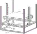
图1为本发明在一实施例中的立体结构示意图一;1 is a schematic diagram 1 of a three-dimensional structure in an embodiment of the present invention;
图2为图1的局部放大示意图;Fig. 2 is the partial enlarged schematic diagram of Fig. 1;
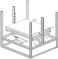
图3为本发明在一实施例中的立体结构示意图二;3 is a second schematic diagram of a three-dimensional structure in an embodiment of the present invention;
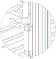
图4为图3的局部放大示意图;Fig. 4 is the partial enlarged schematic diagram of Fig. 3;
图5为本发明在一实施例中的仰视图;Fig. 5 is the bottom view in one embodiment of the present invention;
图6为本发明在一实施例中成型平台的局部示意图。FIG. 6 is a partial schematic diagram of a forming platform in an embodiment of the present invention.
图中所示:Shown in the picture:
21、成型平台;211、承接板;212、调节模组;2121、导向滑槽;2122、调节杆;2123、第一楔块;2124、第二楔块;213、连接部;214、螺母座;215、导向模组;22、竖直驱动组件;221、驱动源;222、齿轮;223、同步皮带轮;224、固定板;225、丝杆;23、固定支架。21, forming platform; 211, receiving plate; 212, adjusting module; 2121, guide chute; 2122, adjusting rod; 2123, first wedge; 2124, second wedge; 213, connecting part; 214,
具体实施方式Detailed ways
下面结合附图对本发明做进一步的详细说明,本发明的前述和其它目的、特征、方面和优点将变得更加明显,以令本领域技术人员参照说明书文字能够据以实施。在附图中,为清晰起见,可对形状和尺寸进行放大,并将在所有图中使用相同的附图标记来指示相同或相似的部件。在下列描述中,诸如中心、厚度、高度、长度、前部、背部、后部、左边、右边、顶部、底部、上部、下部等用词为基于附图所示的方位或位置关系。特别地,“高度”相当于从顶部到底部的尺寸,“宽度”相当于从左边到右边的尺寸,“深度”相当于从前到后的尺寸,“闭合”指代载具方便通过而操作人员无法通过,“环形”相当于循环形状。这些相对术语是为了说明方便起见并且通常并不旨在需要具体取向。涉及附接、联接等的术语(例如,“连接”和“附接”)是指这些结构通过中间结构彼此直接或间接固定或附接的关系、以及可动或刚性附接或关系,除非以其他方式明确地说明。The present invention will be further described in detail below in conjunction with the accompanying drawings, and the foregoing and other objects, features, aspects and advantages of the present invention will become more apparent, so that those skilled in the art can implement them with reference to the description. In the drawings, the shapes and dimensions may be exaggerated for clarity, and the same reference numerals will be used throughout the drawings to refer to the same or like parts. In the following description, terms such as center, thickness, height, length, front, back, rear, left, right, top, bottom, upper, lower, etc. are based on the orientation or positional relationship shown in the drawings. In particular, "height" corresponds to the dimension from top to bottom, "width" corresponds to the dimension from left to right, "depth" corresponds to the dimension from front to back, and "closed" refers to the convenient passage of the carrier and the operator Can't pass, "ring" is equivalent to a loop shape. These relative terms are for convenience of description and are generally not intended to require a specific orientation. Terms referring to attachment, coupling, etc. (eg, "connected" and "attached") refer to the fixed or attached relationship, as well as the movable or rigid attachment or relationship of these structures to each other, directly or indirectly through intervening structures, unless The other way is explicitly stated.
下面,结合附图以及具体实施方式,对本发明做进一步描述,需要说明的是,在不相冲突的前提下,以下描述的各实施例之间或各技术特征之间可以任意组合形成新的实施例。Hereinafter, the present invention will be further described with reference to the accompanying drawings and specific embodiments. It should be noted that, on the premise of no conflict, the embodiments or technical features described below can be arbitrarily combined to form new embodiments. .
如图1所示,一种可调平的3D打印成型平台,包括成型平台21、竖直驱动组件22,其中,As shown in FIG. 1, a flattenable 3D printing forming platform includes a forming
如图3所示,成型平台21包括用于承接物料的承接板211以及用于调节承接板211位置的调节模组212,调节模组212与承接板211连接,通过调整调节模组212在垂直方向上的高度,从而调整承接板211的水平度;As shown in FIG. 3 , the forming
调节模组212的数量不少于三个,调节模组212分布设置在连接部213靠近边缘的位置处,以方便不同的调节模组212调整承接板211上不同的位置,从而达到调整承接板211水平方向的目的,在一优选实施例中,调节模组212的数量为四个,调节模组212设置在承接板211的四边角上,通过分别调节不同的调节模组212,进而调整承接板211的水平度;The number of
竖直驱动组件22,用于驱动成型平台21沿垂直水平面方向移动,由于外部的成型组件在成型平台21逐层成型产品,产品由成型平台21的表面沿垂直方向逐渐成型,为了方便逐层成型,通过竖直驱动组件22驱动成型平台21沿垂直方向移动;The
进一步的,如图3所示,调节模组212包括调节杆2122、楔块,通过调节杆2122调节楔块位置,进而带动承接板211在垂直水平面方向上的运动,从而调节承接板211的水平度;具体地,楔块包括第一楔块2123、第二楔块2124,第一楔块2123、第二楔块2124的斜面贴合,通过第一楔块2123、第二楔块2124相互之间的滑动,使得承接板211在垂直方向上产生位移;调节杆2122驱动第二楔块2124在水平方向上移动,第一楔块2123安装在承接板211,通过调节杆2122驱动第二楔块2124移动以使得第一楔块2123、第二楔块2124间接触的位置产生变化,进而使承接板211沿垂直方向的位置发生改变,以实现调整承接板211水平度的作用。Further, as shown in FIG. 3 , the
进一步地,调节模组212还包括导向滑槽2121,调节杆2122驱动第二楔块2124,使得第二楔块2124沿导向滑槽2121方向滑动,通过导向滑槽2121限制第二楔块2124的运动方向,使得第二楔块2124精确地推动第一楔块2123。Further, the
第一楔块2123与第二楔块2124贴合的斜面上设置导向件,通过导向件引导,使得第二楔块2124相对第一楔块2123沿斜面方向移动,从而保证第一楔块2123与第二楔块2124保持贴合的状态;具体地,导向件包括第二楔块2124上安装的滑块以及第一楔块2123上开设的滑轨,通过滑块与滑轨滑动连接,使得第二楔块2124相对第一楔块2123运动。A guide is provided on the inclined surface where the
在一优选实施例中,成型平台21还包括连接部213,连接部213用于支撑调节模组212,连接部213作为该成型平台21的承接结构,调节模组212设置在连接部213与承接板211之间,从而使得成型平台21形成一稳定的整体结构;In a preferred embodiment, the forming
通过竖直驱动组件22驱动连接部213,进而带动承接板211,使得成型平台21整体沿垂直方向移动,方便成型平台21靠近或远离3D打印头,以满足逐层打印的需要。The connecting
该成型平台还包括固定支架23,固定支架23用于形成成型平台21以及竖直驱动组件22的固定基座;The forming platform also includes a fixing
如图4、5所示,固定支架23上安装用于引导成型平台21运动方向的导向模组215,通过导向模组215与竖直驱动组件22共同限制成型平台21的运动轨迹。As shown in FIGS. 4 and 5 , a
进一步地,竖直驱动组件22包括驱动源221、丝杆225,连接部213上安装有螺母座214;通过丝杆225与螺母座214螺纹连接,使得驱动源221驱使丝杆225,从而使得成型平台21移动。Further, the
如图2所示,固定支架23上安装有固定板224,驱动源221安装在固定板224,从而使得,成型平台21、竖直驱动组件22与固定支架23连接形成一整体;在一优选实施例中,驱动源221与丝杆225间通过齿轮222进行传动,将驱动源221上安装的齿轮222齿数设置的小于丝杆225上安装的齿轮222齿数,减小驱动源221上输出的转速,从而增加输出的扭矩,从而提高驱动源221与丝杆225间传动的稳定性。As shown in FIG. 2, a fixing
采用丝杆225驱动成型平台21驱动,由于丝杆225驱动的精度较高方便暂停,使得在成型平台21打印的产品精度高。The
更进一步地,丝杆225的数量为两个,丝杆225设置在连接部213的两侧;由于成型平台21尺寸较大,同时上放承接有产品,因此,在成型平台21上的重量较重,通过两侧的两丝杆225同时驱动成型平台21,方便从两侧施力,减小了一侧的扭矩,从而保证了丝杆225的使用寿命。Further, the number of the
竖直驱动组件22还包括同步皮带轮223,通过驱动源221驱使同步皮带轮223转动,进而由同步皮带轮223带动两丝杆225运动,利用一驱动源221驱动两丝杆225运动,减少了驱动源221,简化设备,同时,方便同步控制,简化了控制逻辑。The
本发明提供的成型平台,还应具有控制装置、供电装置,相应动作机构都应具有相应的动力机构等,同时具有总装机体等,不再赘述The forming platform provided by the present invention should also have a control device, a power supply device, a corresponding action mechanism should have a corresponding power mechanism, etc., and a general assembly body, etc., which will not be repeated.
本发明提供一种可调平的3D打印成型平台,通过调节杆调节楔块位置,进而带动承接板在垂直水平面方向上的运动,从而调节承接板的水平度,方便承接板保持水平,提高生产精度;通过一驱动源驱动两丝杆运动,减少了驱动源数量,简化设备,方便同步控制,简化了控制逻辑,本发明使用方便,结构简单。The invention provides an adjustable 3D printing forming platform. The position of the wedge is adjusted by the adjusting rod, thereby driving the movement of the receiving plate in the direction of the vertical horizontal plane, so as to adjust the levelness of the receiving plate, which is convenient for the receiving plate to be kept horizontal and improves the production. Accuracy; two screw rods are driven by one driving source, which reduces the number of driving sources, simplifies equipment, facilitates synchronous control, and simplifies control logic. The present invention is convenient to use and simple in structure.
以上,仅为本发明的较佳实施例而已,并非对本发明作任何形式上的限制;凡本行业的普通技术人员均可按说明书附图所示和以上而顺畅地实施本发明;但是,凡熟悉本专业的技术人员在不脱离本发明技术方案范围内,利用以上所揭示的技术内容而做出的些许更动、修饰与演变的等同变化,均为本发明的等效实施例;同时,凡依据本发明的实质技术对以上实施例所作的任何等同变化的更动、修饰与演变等,均仍属于本发明的技术方案的保护范围之内。The above are only preferred embodiments of the present invention, and do not limit the present invention in any form; any person of ordinary skill in the industry can smoothly implement the present invention as shown in the accompanying drawings and above; however, any Those skilled in the art, without departing from the scope of the technical solution of the present invention, make use of the above-disclosed technical content to make some changes, modifications and equivalent changes of evolution are equivalent embodiments of the present invention; at the same time, Any alteration, modification and evolution of any equivalent changes made to the above embodiments according to the essential technology of the present invention still fall within the protection scope of the technical solution of the present invention.
Claims (10)
Translated fromChinesePriority Applications (1)
| Application Number | Priority Date | Filing Date | Title |
|---|---|---|---|
| CN202011130854.3ACN112571796A (en) | 2020-10-21 | 2020-10-21 | 3D printing forming platform capable of being leveled |
Applications Claiming Priority (1)
| Application Number | Priority Date | Filing Date | Title |
|---|---|---|---|
| CN202011130854.3ACN112571796A (en) | 2020-10-21 | 2020-10-21 | 3D printing forming platform capable of being leveled |
Publications (1)
| Publication Number | Publication Date |
|---|---|
| CN112571796Atrue CN112571796A (en) | 2021-03-30 |
Family
ID=75119925
Family Applications (1)
| Application Number | Title | Priority Date | Filing Date |
|---|---|---|---|
| CN202011130854.3APendingCN112571796A (en) | 2020-10-21 | 2020-10-21 | 3D printing forming platform capable of being leveled |
Country Status (1)
| Country | Link |
|---|---|
| CN (1) | CN112571796A (en) |
Cited By (2)
| Publication number | Priority date | Publication date | Assignee | Title |
|---|---|---|---|---|
| CN113414981A (en)* | 2021-07-16 | 2021-09-21 | 内蒙古工业大学 | Efficient FDM3D printing device |
| CN116619740A (en)* | 2023-06-15 | 2023-08-22 | 南京铖联激光科技有限公司 | Compacting and leveling device and compacting and leveling method for molding platform of resin printer |
Citations (11)
| Publication number | Priority date | Publication date | Assignee | Title |
|---|---|---|---|---|
| US4439961A (en)* | 1981-11-03 | 1984-04-03 | Witte Donald H | Leveling and locating device and method of using |
| CN201077075Y (en)* | 2007-09-27 | 2008-06-25 | 天津市天发重型水电设备制造有限公司 | Layout block leveling device |
| CN204430571U (en)* | 2014-12-26 | 2015-07-01 | 深圳市火焱激光科技有限公司 | High-accuracy hoistable platform and laser cutting device |
| CN105618754A (en)* | 2015-09-06 | 2016-06-01 | 苏州西帝摩三维打印科技有限公司 | Selective laser melting multifunctional forming working table |
| CN207630532U (en)* | 2017-08-07 | 2018-07-20 | 北京紫熙科技发展有限公司 | 3d printer |
| CN207724846U (en)* | 2017-11-15 | 2018-08-14 | 厦门螺壳电子科技有限公司 | A kind of 3D printer |
| CN208358335U (en)* | 2018-05-28 | 2019-01-11 | 无锡左右精密机械有限公司 | A kind of three column hydraulic tools for processing planet carrier |
| CN209649485U (en)* | 2018-12-27 | 2019-11-19 | 苏州紫金港智能制造装备有限公司 | A kind of 3D printer bottom plate Manual micromatic device |
| CN210100718U (en)* | 2018-12-26 | 2020-02-21 | 宁波速美科技有限公司 | High temperature 3D printer self-adaptation leveling platform to PEEK material shaping |
| WO2020087048A2 (en)* | 2018-10-25 | 2020-04-30 | Make Composites, Inc. | Systems and methods of printing with fiber-reinforced materials |
| CN210477826U (en)* | 2019-06-20 | 2020-05-08 | 广州番禺职业技术学院 | 3D printer and synchronous lifting mechanism for printing platform thereof |
- 2020
- 2020-10-21CNCN202011130854.3Apatent/CN112571796A/enactivePending
Patent Citations (11)
| Publication number | Priority date | Publication date | Assignee | Title |
|---|---|---|---|---|
| US4439961A (en)* | 1981-11-03 | 1984-04-03 | Witte Donald H | Leveling and locating device and method of using |
| CN201077075Y (en)* | 2007-09-27 | 2008-06-25 | 天津市天发重型水电设备制造有限公司 | Layout block leveling device |
| CN204430571U (en)* | 2014-12-26 | 2015-07-01 | 深圳市火焱激光科技有限公司 | High-accuracy hoistable platform and laser cutting device |
| CN105618754A (en)* | 2015-09-06 | 2016-06-01 | 苏州西帝摩三维打印科技有限公司 | Selective laser melting multifunctional forming working table |
| CN207630532U (en)* | 2017-08-07 | 2018-07-20 | 北京紫熙科技发展有限公司 | 3d printer |
| CN207724846U (en)* | 2017-11-15 | 2018-08-14 | 厦门螺壳电子科技有限公司 | A kind of 3D printer |
| CN208358335U (en)* | 2018-05-28 | 2019-01-11 | 无锡左右精密机械有限公司 | A kind of three column hydraulic tools for processing planet carrier |
| WO2020087048A2 (en)* | 2018-10-25 | 2020-04-30 | Make Composites, Inc. | Systems and methods of printing with fiber-reinforced materials |
| CN210100718U (en)* | 2018-12-26 | 2020-02-21 | 宁波速美科技有限公司 | High temperature 3D printer self-adaptation leveling platform to PEEK material shaping |
| CN209649485U (en)* | 2018-12-27 | 2019-11-19 | 苏州紫金港智能制造装备有限公司 | A kind of 3D printer bottom plate Manual micromatic device |
| CN210477826U (en)* | 2019-06-20 | 2020-05-08 | 广州番禺职业技术学院 | 3D printer and synchronous lifting mechanism for printing platform thereof |
Cited By (2)
| Publication number | Priority date | Publication date | Assignee | Title |
|---|---|---|---|---|
| CN113414981A (en)* | 2021-07-16 | 2021-09-21 | 内蒙古工业大学 | Efficient FDM3D printing device |
| CN116619740A (en)* | 2023-06-15 | 2023-08-22 | 南京铖联激光科技有限公司 | Compacting and leveling device and compacting and leveling method for molding platform of resin printer |
Similar Documents
| Publication | Publication Date | Title |
|---|---|---|
| CN203380365U (en) | Novel metal powder melting quick forming machine | |
| CN204799942U (en) | Laser sintering 3D printer | |
| CN105773984B (en) | A 3D printer with curved surface processing characteristics | |
| CN112571796A (en) | 3D printing forming platform capable of being leveled | |
| CN103786346B (en) | A kind of zoomable face exposure projections 3D prints rapid prototyping system and method | |
| CN105071687B (en) | Stick-slip driven cross-scale precision positioning platform with side friction adjustment mechanism | |
| WO2018188386A1 (en) | Selective laser melting device and assembly, and 3d printer | |
| CN109079957A (en) | A kind of field operation type concrete 3D printing system and its assembly method | |
| CN106426910B (en) | A kind of large-scale double crossbeam industry 3D printers | |
| CN109016508A (en) | 3D printer transmission mechanism | |
| CN204094145U (en) | For the printout locating platform of three-dimensional printer | |
| CN106825573A (en) | Melt component and 3D printer in selective laser | |
| CN210100718U (en) | High temperature 3D printer self-adaptation leveling platform to PEEK material shaping | |
| WO2022062224A1 (en) | 3d printer | |
| CN207841655U (en) | Ceramic material 3D printing is equipped | |
| CN218315255U (en) | High accuracy 3D printer | |
| CN203209690U (en) | Longitudinal movement device for selective laser sintering forming platform | |
| CN107160677B (en) | A method to prevent the occurrence of dislocation of workpiece in SLS forming process | |
| CN114102793B (en) | Ceramic additive and subtractive composite manufacturing equipment | |
| CN212708022U (en) | Movement device of 3D printer | |
| CN206690537U (en) | It is a kind of to flow continuous supplementation DLP light curring units naturally | |
| WO2022077770A1 (en) | 3d printer | |
| CN115503232A (en) | Six-degree-of-freedom photocuring 3D printing device and 3D printing method | |
| CN112519212A (en) | 3D printer with suspension type platform | |
| CN210759269U (en) | 3D printer convenient to leveling |
Legal Events
| Date | Code | Title | Description |
|---|---|---|---|
| PB01 | Publication | ||
| PB01 | Publication | ||
| SE01 | Entry into force of request for substantive examination | ||
| SE01 | Entry into force of request for substantive examination | ||
| RJ01 | Rejection of invention patent application after publication | ||
| RJ01 | Rejection of invention patent application after publication | Application publication date:20210330 |