CN112566680B - Movable infusion pump and components for use therewith - Google Patents
Movable infusion pump and components for use therewithDownload PDFInfo
- Publication number
- CN112566680B CN112566680BCN201880045168.0ACN201880045168ACN112566680BCN 112566680 BCN112566680 BCN 112566680BCN 201880045168 ACN201880045168 ACN 201880045168ACN 112566680 BCN112566680 BCN 112566680B
- Authority
- CN
- China
- Prior art keywords
- cannula
- seal
- carrier
- sleeve
- trocar
- Prior art date
- Legal status (The legal status is an assumption and is not a legal conclusion. Google has not performed a legal analysis and makes no representation as to the accuracy of the status listed.)
- Active
Links
Images


Classifications
- A—HUMAN NECESSITIES
- A61—MEDICAL OR VETERINARY SCIENCE; HYGIENE
- A61M—DEVICES FOR INTRODUCING MEDIA INTO, OR ONTO, THE BODY; DEVICES FOR TRANSDUCING BODY MEDIA OR FOR TAKING MEDIA FROM THE BODY; DEVICES FOR PRODUCING OR ENDING SLEEP OR STUPOR
- A61M5/00—Devices for bringing media into the body in a subcutaneous, intra-vascular or intramuscular way; Accessories therefor, e.g. filling or cleaning devices, arm-rests
- A61M5/14—Infusion devices, e.g. infusing by gravity; Blood infusion; Accessories therefor
- A61M5/158—Needles for infusions; Accessories therefor, e.g. for inserting infusion needles, or for holding them on the body
- A—HUMAN NECESSITIES
- A61—MEDICAL OR VETERINARY SCIENCE; HYGIENE
- A61M—DEVICES FOR INTRODUCING MEDIA INTO, OR ONTO, THE BODY; DEVICES FOR TRANSDUCING BODY MEDIA OR FOR TAKING MEDIA FROM THE BODY; DEVICES FOR PRODUCING OR ENDING SLEEP OR STUPOR
- A61M5/00—Devices for bringing media into the body in a subcutaneous, intra-vascular or intramuscular way; Accessories therefor, e.g. filling or cleaning devices, arm-rests
- A61M5/14—Infusion devices, e.g. infusing by gravity; Blood infusion; Accessories therefor
- A61M5/142—Pressure infusion, e.g. using pumps
- A61M5/14244—Pressure infusion, e.g. using pumps adapted to be carried by the patient, e.g. portable on the body
- A61M5/14248—Pressure infusion, e.g. using pumps adapted to be carried by the patient, e.g. portable on the body of the skin patch type
- A—HUMAN NECESSITIES
- A61—MEDICAL OR VETERINARY SCIENCE; HYGIENE
- A61M—DEVICES FOR INTRODUCING MEDIA INTO, OR ONTO, THE BODY; DEVICES FOR TRANSDUCING BODY MEDIA OR FOR TAKING MEDIA FROM THE BODY; DEVICES FOR PRODUCING OR ENDING SLEEP OR STUPOR
- A61M5/00—Devices for bringing media into the body in a subcutaneous, intra-vascular or intramuscular way; Accessories therefor, e.g. filling or cleaning devices, arm-rests
- A61M5/14—Infusion devices, e.g. infusing by gravity; Blood infusion; Accessories therefor
- A61M5/142—Pressure infusion, e.g. using pumps
- A61M5/145—Pressure infusion, e.g. using pumps using pressurised reservoirs, e.g. pressurised by means of pistons
- A61M5/1452—Pressure infusion, e.g. using pumps using pressurised reservoirs, e.g. pressurised by means of pistons pressurised by means of pistons
- A—HUMAN NECESSITIES
- A61—MEDICAL OR VETERINARY SCIENCE; HYGIENE
- A61B—DIAGNOSIS; SURGERY; IDENTIFICATION
- A61B17/00—Surgical instruments, devices or methods
- A61B17/34—Trocars; Puncturing needles
- A61B17/3415—Trocars; Puncturing needles for introducing tubes or catheters, e.g. gastrostomy tubes, drain catheters
- A—HUMAN NECESSITIES
- A61—MEDICAL OR VETERINARY SCIENCE; HYGIENE
- A61M—DEVICES FOR INTRODUCING MEDIA INTO, OR ONTO, THE BODY; DEVICES FOR TRANSDUCING BODY MEDIA OR FOR TAKING MEDIA FROM THE BODY; DEVICES FOR PRODUCING OR ENDING SLEEP OR STUPOR
- A61M5/00—Devices for bringing media into the body in a subcutaneous, intra-vascular or intramuscular way; Accessories therefor, e.g. filling or cleaning devices, arm-rests
- A61M5/14—Infusion devices, e.g. infusing by gravity; Blood infusion; Accessories therefor
- A61M5/142—Pressure infusion, e.g. using pumps
- A61M5/14244—Pressure infusion, e.g. using pumps adapted to be carried by the patient, e.g. portable on the body
- A61M5/14248—Pressure infusion, e.g. using pumps adapted to be carried by the patient, e.g. portable on the body of the skin patch type
- A61M2005/14252—Pressure infusion, e.g. using pumps adapted to be carried by the patient, e.g. portable on the body of the skin patch type with needle insertion means
- A—HUMAN NECESSITIES
- A61—MEDICAL OR VETERINARY SCIENCE; HYGIENE
- A61M—DEVICES FOR INTRODUCING MEDIA INTO, OR ONTO, THE BODY; DEVICES FOR TRANSDUCING BODY MEDIA OR FOR TAKING MEDIA FROM THE BODY; DEVICES FOR PRODUCING OR ENDING SLEEP OR STUPOR
- A61M5/00—Devices for bringing media into the body in a subcutaneous, intra-vascular or intramuscular way; Accessories therefor, e.g. filling or cleaning devices, arm-rests
- A61M5/14—Infusion devices, e.g. infusing by gravity; Blood infusion; Accessories therefor
- A61M5/142—Pressure infusion, e.g. using pumps
- A61M5/14244—Pressure infusion, e.g. using pumps adapted to be carried by the patient, e.g. portable on the body
- A61M2005/14268—Pressure infusion, e.g. using pumps adapted to be carried by the patient, e.g. portable on the body with a reusable and a disposable component
- A—HUMAN NECESSITIES
- A61—MEDICAL OR VETERINARY SCIENCE; HYGIENE
- A61M—DEVICES FOR INTRODUCING MEDIA INTO, OR ONTO, THE BODY; DEVICES FOR TRANSDUCING BODY MEDIA OR FOR TAKING MEDIA FROM THE BODY; DEVICES FOR PRODUCING OR ENDING SLEEP OR STUPOR
- A61M5/00—Devices for bringing media into the body in a subcutaneous, intra-vascular or intramuscular way; Accessories therefor, e.g. filling or cleaning devices, arm-rests
- A61M5/14—Infusion devices, e.g. infusing by gravity; Blood infusion; Accessories therefor
- A61M5/142—Pressure infusion, e.g. using pumps
- A61M5/145—Pressure infusion, e.g. using pumps using pressurised reservoirs, e.g. pressurised by means of pistons
- A61M2005/14506—Pressure infusion, e.g. using pumps using pressurised reservoirs, e.g. pressurised by means of pistons mechanically driven, e.g. spring or clockwork
- A—HUMAN NECESSITIES
- A61—MEDICAL OR VETERINARY SCIENCE; HYGIENE
- A61M—DEVICES FOR INTRODUCING MEDIA INTO, OR ONTO, THE BODY; DEVICES FOR TRANSDUCING BODY MEDIA OR FOR TAKING MEDIA FROM THE BODY; DEVICES FOR PRODUCING OR ENDING SLEEP OR STUPOR
- A61M5/00—Devices for bringing media into the body in a subcutaneous, intra-vascular or intramuscular way; Accessories therefor, e.g. filling or cleaning devices, arm-rests
- A61M5/14—Infusion devices, e.g. infusing by gravity; Blood infusion; Accessories therefor
- A61M5/158—Needles for infusions; Accessories therefor, e.g. for inserting infusion needles, or for holding them on the body
- A61M2005/1583—Needle extractors
- A—HUMAN NECESSITIES
- A61—MEDICAL OR VETERINARY SCIENCE; HYGIENE
- A61M—DEVICES FOR INTRODUCING MEDIA INTO, OR ONTO, THE BODY; DEVICES FOR TRANSDUCING BODY MEDIA OR FOR TAKING MEDIA FROM THE BODY; DEVICES FOR PRODUCING OR ENDING SLEEP OR STUPOR
- A61M5/00—Devices for bringing media into the body in a subcutaneous, intra-vascular or intramuscular way; Accessories therefor, e.g. filling or cleaning devices, arm-rests
- A61M5/14—Infusion devices, e.g. infusing by gravity; Blood infusion; Accessories therefor
- A61M5/158—Needles for infusions; Accessories therefor, e.g. for inserting infusion needles, or for holding them on the body
- A61M2005/1585—Needle inserters
- A—HUMAN NECESSITIES
- A61—MEDICAL OR VETERINARY SCIENCE; HYGIENE
- A61M—DEVICES FOR INTRODUCING MEDIA INTO, OR ONTO, THE BODY; DEVICES FOR TRANSDUCING BODY MEDIA OR FOR TAKING MEDIA FROM THE BODY; DEVICES FOR PRODUCING OR ENDING SLEEP OR STUPOR
- A61M2205/00—General characteristics of the apparatus
- A61M2205/18—General characteristics of the apparatus with alarm
- A—HUMAN NECESSITIES
- A61—MEDICAL OR VETERINARY SCIENCE; HYGIENE
- A61M—DEVICES FOR INTRODUCING MEDIA INTO, OR ONTO, THE BODY; DEVICES FOR TRANSDUCING BODY MEDIA OR FOR TAKING MEDIA FROM THE BODY; DEVICES FOR PRODUCING OR ENDING SLEEP OR STUPOR
- A61M2205/00—General characteristics of the apparatus
- A61M2205/33—Controlling, regulating or measuring
- A61M2205/3317—Electromagnetic, inductive or dielectric measuring means
- A—HUMAN NECESSITIES
- A61—MEDICAL OR VETERINARY SCIENCE; HYGIENE
- A61M—DEVICES FOR INTRODUCING MEDIA INTO, OR ONTO, THE BODY; DEVICES FOR TRANSDUCING BODY MEDIA OR FOR TAKING MEDIA FROM THE BODY; DEVICES FOR PRODUCING OR ENDING SLEEP OR STUPOR
- A61M2205/00—General characteristics of the apparatus
- A61M2205/82—Internal energy supply devices
- A61M2205/8206—Internal energy supply devices battery-operated
Landscapes
- Health & Medical Sciences (AREA)
- Vascular Medicine (AREA)
- Engineering & Computer Science (AREA)
- Anesthesiology (AREA)
- Biomedical Technology (AREA)
- Heart & Thoracic Surgery (AREA)
- Hematology (AREA)
- Life Sciences & Earth Sciences (AREA)
- Animal Behavior & Ethology (AREA)
- General Health & Medical Sciences (AREA)
- Public Health (AREA)
- Veterinary Medicine (AREA)
- Dermatology (AREA)
- Infusion, Injection, And Reservoir Apparatuses (AREA)
Abstract
Description
Translated fromChinese相关申请的交叉引用Cross References to Related Applications
本申请要求2017年7月4日提交的先前提交的美国临时专利申请序列号62/528,486的权益和优先权,该美国临时专利申请全文以引用方式并入本文。This application claims the benefit of and priority to previously filed U.S. Provisional Patent Application Serial No. 62/528,486, filed July 4, 2017, which is incorporated herein by reference in its entirety.
背景技术Background technique
1.技术领域1. Technical field
本设备和方法整体涉及可动输注泵以及用于这些泵的插入器和密封件。The present apparatus and methods relate generally to movable infusion pumps and inserters and seals for these pumps.
2.相关技术描述2.Description of related technologies
可动输注泵(在本文中也简称为“输注泵”)是相对较小、至少基本上独立的设备,其用于将药品和其他不溶性物质(统称为“药物”)引入患者体内。一些输注泵被配置为佩戴在皮带上、携带在衣服口袋中等。其他输注泵被配置为以类似贴片的方式粘附到皮肤。输注泵的优点在于,它们可以用于例如在临床环境外部持续地或甚至连续地皮下引入(或“输注”)药物。输注泵的优点还在于,它们极大地减小皮下进入事件(诸如基于针头的注射)的频率。可由输注泵引入的药物的一个示例是胰岛素的液体制剂。可由输注泵引入的其他示例性药物包括但不限于治疗癌症的药品和抑制疼痛感知的药品。Movable infusion pumps (also referred to herein simply as "infusion pumps") are relatively small, at least substantially self-contained devices that are used to introduce pharmaceuticals and other insoluble substances (collectively "drugs") into a patient's body. Some infusion pumps are configured to be worn on a belt, carried in a clothing pocket, or the like. Other infusion pumps are configured to adhere to the skin in a patch-like fashion. An advantage of infusion pumps is that they can be used for the continuous or even continuous subcutaneous introduction (or "infusion") of drugs, for example outside of a clinical setting. Infusion pumps are also advantageous in that they greatly reduce the frequency of subcutaneous access events such as needle-based injections. One example of a drug that can be introduced by an infusion pump is a liquid formulation of insulin. Other exemplary drugs that may be introduced by an infusion pump include, but are not limited to, drugs that treat cancer and drugs that inhibit pain perception.
许多常规输注泵已经改善患者的健康状况和生活质量。然而,本发明人已经确定常规输注泵易于进行宽泛范围的改善。作为示例而非限制,本发明人已经确定,期望提供一种输注泵,该输注泵比常规输注泵更小、更简单、更可靠并且成本更低,同时还比常规输注泵更加准确和用户友好。Many conventional infusion pumps have improved patient health and quality of life. However, the present inventors have determined that conventional infusion pumps are susceptible to a wide range of improvements. By way of example and not limitation, the present inventors have determined that it is desirable to provide an infusion pump that is smaller, simpler, more reliable, and less costly than conventional infusion pumps, while also being more efficient than conventional infusion pumps. Accurate and user friendly.
发明内容Contents of the invention
一种套管插入机构包括:套管载体;以及具有密封环的套管密封件,其中套管载体通过用由于套管密封件的顶部上的向下压缩力而增加的套管密封件上的径向夹紧力增加套管载体和密封环之间的接触来提供增强的套管密封件。本发明还包括具有这种机构的输注泵、具有这种机构的输注泵子组件(诸如一次性组件)以及相关方法。A cannula insertion mechanism includes: a cannula carrier; and a cannula seal having a seal ring, wherein the cannula carrier passes through the cannula carrier with a pressure on the cannula seal that increases due to downward compressive force on top of the cannula seal. The radial clamping force increases the contact between the sleeve carrier and the seal ring to provide an enhanced sleeve seal. The invention also includes infusion pumps having such mechanisms, infusion pump subassemblies (such as disposable assemblies) having such mechanisms, and related methods.
一种套管插入机构包括:套管载体;具有密封环的套管密封件;以及密封件保持器,其中套管载体通过用由于套管密封件的顶部上的向下压缩力而增加的套管密封件上的径向夹紧力增加套管载体和密封环之间的接触来提供增强的套管密封件。本发明还包括具有这种机构的输注泵、具有这种机构的输注泵子组件(诸如一次性组件)以及相关方法。A cannula insertion mechanism comprising: a cannula carrier; a cannula seal having a seal ring; The radial clamping force on the tube seal increases the contact between the sleeve carrier and the seal ring to provide a reinforced sleeve seal. The invention also includes infusion pumps having such mechanisms, infusion pump subassemblies (such as disposable assemblies) having such mechanisms, and related methods.
附图说明Description of drawings
将参照附图对示例性实施方案进行详细描述。Exemplary embodiments will be described in detail with reference to the accompanying drawings.
图1A是处于组装状态的示例性输注泵系统的透视图。1A is a perspective view of an exemplary infusion pump system in an assembled state.
图1B是图1A所示的输注泵系统的分解透视图,该输注泵系统包括耐用组件和一次性组件。FIG. 1B is an exploded perspective view of the infusion pump system shown in FIG. 1A including durable components and disposable components.
图2是图1A和图1B所示的输注泵系统的某些部件的顶视图。2 is a top view of certain components of the infusion pump system shown in FIGS. 1A and 1B .
图2A是示出图1A和图1B所示的输注泵系统的使用的示意图。FIG. 2A is a schematic diagram illustrating use of the infusion pump system shown in FIGS. 1A and 1B .
图2B是示出图1A和图1B所示的输注泵系统的另一种使用的示意图。2B is a schematic diagram illustrating another use of the infusion pump system shown in FIGS. 1A and 1B .
图3A是示例性耐用组件的透视图。3A is a perspective view of an exemplary durable assembly.
图3B是图3A所示的耐用组件的某些部件的透视图。Figure 3B is a perspective view of certain components of the durable assembly shown in Figure 3A.
图4A是示例性一次性组件的透视图。Figure 4A is a perspective view of an exemplary disposable assembly.
图4B是图4A所示的一次性组件的某些部件的透视图。Figure 4B is a perspective view of certain components of the disposable assembly shown in Figure 4A.
图5A是示例性输注泵系统的耐用组件和一次性组件的某些部件的透视图。5A is a perspective view of certain components of a durable assembly and a disposable assembly of an exemplary infusion pump system.
图5B是图5A所示的示例性耐用组件的部件的透视图。5B is a perspective view of components of the exemplary durable assembly shown in FIG. 5A.
图5C是图5A所示的示例性一次性组件的部件的透视图。5C is a perspective view of components of the exemplary disposable assembly shown in FIG. 5A.
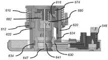
图6是图5A的示例性输注泵系统的部件的透视截面图,揭示了耐用组件和一次性组件的某些部件之间的间隙。6 is a perspective cross-sectional view of components of the exemplary infusion pump system of FIG. 5A, revealing gaps between certain components of the durable assembly and the disposable assembly.
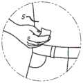
图7是示出正在被清洁的患者皮肤的前视图。Fig. 7 is a front view showing the patient's skin being cleaned.
图8是示出示例性一次性组件移除和替换方法的流程图。8 is a flowchart illustrating an exemplary disposable component removal and replacement method.
图9A是处于组装状态的另一个示例性输注泵系统的透视图。9A is a perspective view of another exemplary infusion pump system in an assembled state.
图9B是图9A的输注泵系统的示例性耐用组件的透视图。9B is a perspective view of exemplary durable components of the infusion pump system of FIG. 9A.
图9C是图9B所示的耐用组件的某些部件的透视图。Figure 9C is a perspective view of certain components of the durable assembly shown in Figure 9B.
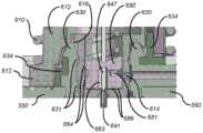
图9D是图9A的输注泵系统的示例性一次性组件的透视图。9D is a perspective view of an exemplary disposable assembly of the infusion pump system of FIG. 9A.
图9E是图9D所示的一次性组件的某些部件的透视图。Figure 9E is a perspective view of certain components of the disposable assembly shown in Figure 9D.
图10A是在移除使用前拉动插头PBUP 517之前的另一个示例性输注泵系统(以组装状态一示出)的透视图。10A is a perspective view of another exemplary infusion pump system (shown in assembled state one) prior to removal of the pre-use pull plug PBUP 517 .
图10B是图10A的输注泵系统的底部的透视图。10B is a perspective view of the bottom of the infusion pump system of FIG. 10A.
图10C是图10A和图10B的输注泵系统的示例性耐用组件的透视图。10C is a perspective view of exemplary durable components of the infusion pump system of FIGS. 10A and 10B .
图10D和图10E是图10C所示的耐用组件的某些部件的透视图。10D and 10E are perspective views of certain components of the durable assembly shown in FIG. 10C.
图10F是图10A的输注泵系统的示例性一次性组件的透视图。10F is a perspective view of an exemplary disposable assembly of the infusion pump system of FIG. 10A.
图10G是图10F所示的一次性组件的某些部件的透视图。Figure 10G is a perspective view of certain components of the disposable assembly shown in Figure 10F.
图10H是示出图10G所示的一次性组件的某些部件(以状态一示出)的截面图。Figure 10H is a cross-sectional view showing certain components (shown in state one) of the disposable assembly shown in Figure 10G.
图11A和图11B是在套管插入之前的一次性组件的某些示例性部件(以状态二示出)的透视图。11A and 11B are perspective views of certain exemplary components of the disposable assembly (shown in state two) prior to cannula insertion.
图11C是示出用于与图11A和图11B的部件一起使用的附加示例性部件(以套管插入之前的位置示出)的侧视图。11C is a side view showing additional exemplary components for use with the components of FIGS. 11A and 11B , shown in a position prior to cannula insertion.
图11D是示出用于与图11A至图11C的部件一起使用的附加示例性部件(以套管插入之前的位置示出)的截面图。11D is a cross-sectional view illustrating additional exemplary components for use with the components of FIGS. 11A-11C , shown in a position prior to cannula insertion.
图12A是在套管插入之后但在套管针缩回之前的图11D的部件(以状态三示出)的截面图。12A is a cross-sectional view of the components of FIG. 11D (shown in state three) after cannula insertion but before trocar retraction.
图12B是示出用于与图12A的部件一起使用的附加示例性部件(以套管插入之后但在套管针缩回之前的位置示出)的透视图。12B is a perspective view showing additional exemplary components for use with that of FIG. 12A (shown in a position after cannula insertion but before trocar retraction).
图13A是在套管插入之后以及在套管针缩回之后的图11D和图12A的部件(以状态四示出)的截面图。13A is a cross-sectional view of the components of FIGS. 11D and 12A (shown in state four) after cannula insertion and after trocar retraction.
图13B是示出用于与图13A的部件一起使用的附加示例性部件(以套管插入之后以及在套管针缩回之后的位置示出)的透视图。13B is a perspective view showing additional exemplary components for use with the components of FIG. 13A (shown in position after cannula insertion and after trocar retraction).
图13C和图13D是图3A的组件的某些示例性部件的截面图。13C and 13D are cross-sectional views of certain exemplary components of the assembly of FIG. 3A.
图14A是示出在移除使用前拉动插头PBUP 517a之前的一次性组件的某些替代部件(以状态一示出)的截面图。Figure 14A is a cross-sectional view showing some alternate components (shown in state one) of the disposable assembly prior to removal of the pre-use
图14B是示出在移除PBUP 517a之后但在套管插入之前的图14A的一次性组件的另外替代部件(以状态二示出)的透视截面图。Figure 14B is a perspective cross-sectional view showing an additional alternative component of the disposable assembly of Figure 14A (shown in state two) after removal of the
图14C和图14D是在插入套管时的图14B的某些部件和特征(在从状态二到状态三的过渡期间示出)的截面图。14C and 14D are cross-sectional views of certain components and features of FIG. 14B (shown during the transition from state two to state three) as the cannula is inserted.
图14E是一旦插入套管时的图14B的某些部件和特征(以状态三示出)的截面图。Figure 14E is a cross-sectional view of certain components and features of Figure 14B (shown in state three) once inserted into the cannula.
图14F是在套管插入之后以及套管针缩回之后的图14B的某些部件和特征(以状态四示出)的截面图。14F is a cross-sectional view of certain components and features of FIG. 14B (shown in state four) after cannula insertion and trocar retraction.
具体实施方式Detailed ways
以下是实施本发明的目前最好的已知方式的详细描述。该描述不是限制性的,而仅仅是为了说明本发明的一般原理的目的。The following is a detailed description of the best presently known mode of carrying out the invention. This description is not limiting, but merely for the purpose of illustrating the general principles of the invention.
在这里还应当指出的是,本说明书描述了特别适合于皮下输送诸如U-500胰岛素的高浓度胰岛素(即,U-200胰岛素及以上)以及诸如U-100胰岛素的较低浓度胰岛素的结构和方法。然而,应当理解,本发明适用于各种输注泵和药物。作为示例而非限制,本发明可以为了流体位移而采用具有柱塞的贮存器、以柱塞推动器形式的流体位移设备、以及包括电动机或其他流体位移设备的驱动机构,而无论采用的贮存器的类型、活塞泵(例如,电磁泵)、MEMS泵、蠕动泵和任何其他合适的泵以及对应驱动机构。在以下专利中描述了示例性输注泵,该输注泵包括具有柱塞(有时与以柱塞推动器形式的流体位移设备结合)的贮存器以及驱动机构:2010年9月24日提交的美国专利申请序列号12/890,207和对应美国专利号8,777,901,这两个专利的全文以引用方式并入;2014年9月30日提交的美国临时专利申请序列号62/057,273、2015年9月29日提交的对应美国专利申请序列号14/869,906和对应美国专利公开号2016/0089491,这些专利中的每一个的全文以引用方式并入;2015年2月18日提交的美国临时专利申请序列号62/117,565、2016年2月11日提交的对应美国专利申请序列号15/042,093和对应美国专利公开号2016/0235913,这些专利中的每一个的全文也以引用方式并入;以及2016年2月12日提交的美国临时专利申请序列号62/294,941和2017年2月12日提交的对应美国专利申请序列号15/430,513,这两个专利的全文也以引用方式并入。本发明还适用于诸如例如以下的药物:用于掩盖疼痛的药品、化学疗法和其他癌症相关药品、抗生素、激素、GLP-1、胰高血糖素、包括可能需要高水平的输送准确度的大分子和蛋白质的各种其他药品,以及适用于诸如U-500胰岛素的相对较高浓度胰岛素(即,U-200胰岛素及以上)以及诸如U-100胰岛素的较低浓度胰岛素。2012年5月18日提交的美国申请序列号13/475,843、和对应美国专利号9,114,208、以及上述美国专利号8,777,901、上述美国专利公开号2016/0089491和上述美国专利申请的序列号15/430,513各自还描述了患者与输注泵(诸如本文所述的示例性输注泵)的相互作用和输注泵的使用。It should also be noted here that this specification describes structures and structures that are particularly suitable for the subcutaneous delivery of high concentrations of insulin such as U-500 insulin (i.e., U-200 insulin and above) as well as lower concentrations of insulin such as U-100 insulin. method. However, it should be understood that the present invention is applicable to a wide variety of infusion pumps and medications. By way of example and not limitation, the present invention may employ a reservoir with a plunger, a fluid displacement device in the form of a plunger pusher, and a drive mechanism including an electric motor or other fluid displacement device for fluid displacement, regardless of the reservoir employed Types of piston pumps (eg electromagnetic pumps), MEMS pumps, peristaltic pumps and any other suitable pumps and corresponding drive mechanisms. An exemplary infusion pump including a reservoir with a plunger (sometimes combined with a fluid displacement device in the form of a plunger pusher) and a drive mechanism is described in the following patent: filed September 24, 2010 U.S. Patent Application Serial No. 12/890,207 and corresponding U.S. Patent No. 8,777,901, both of which are incorporated by reference in their entirety; U.S. Provisional Patent Application Serial No. 62/057,273 filed September 30, 2014, filed September 29, 2015 Corresponding U.S. Patent Application Serial No. 14/869,906 and corresponding U.S. Patent Publication No. 2016/0089491 filed on , each of which is incorporated by reference in its entirety; U.S. Provisional Patent Application Serial No. filed on February 18, 2015 62/117,565, corresponding U.S. Patent Application Serial No. 15/042,093 filed February 11, 2016, and corresponding U.S. Patent Publication No. 2016/0235913, each of which is also incorporated by reference in its entirety; and 2016 2 U.S. Provisional Patent Application Serial No. 62/294,941, filed February 12, and corresponding U.S. Patent Application Serial No. 15/430,513, filed February 12, 2017, both of which are also incorporated by reference in their entirety. The invention is also applicable to drugs such as, for example, drugs used to mask pain, chemotherapy and other cancer-related drugs, antibiotics, hormones, GLP-1, glucagon, including large Various other pharmaceutical products of molecules and proteins, and suitable for relatively higher concentration insulins such as U-500 insulin (ie, U-200 insulin and above) and lower concentration insulins such as U-100 insulin. U.S. Application Serial No. 13/475,843 filed May 18, 2012, and corresponding U.S. Patent No. 9,114,208, and the aforementioned U.S. Patent No. 8,777,901, the aforementioned U.S. Patent Publication No. 2016/0089491, and the aforementioned U.S. Patent Application Serial No. 15/430,513 Patient interaction with and use of infusion pumps, such as the exemplary infusion pumps described herein, are also described.
如上所述,一些可动输注泵旨在佩戴在皮带上、携带在口袋中、或以其他方式支撑在某种类型的保持器内(统称为“口袋泵”)。此类输注泵通过伸长管将流体从贮存器转移到输注器。皮下进入可通过输注器中的套管获得。其他可动输注泵旨在粘附到输送部位上方的皮肤上(有时称为“贴片泵”)。在此,套管或其他皮下进入设备可直接从输注设备延伸。在任一种情况下,这些泵以约为6mm的深度通过套管皮下输注药物。给定这些使用模式,患者通常优选设备尽可能小以使其更舒适、更不引人注目且更不可见。此外,患者需要一种容易和方便使用的设备。As noted above, some movable infusion pumps are intended to be worn on a belt, carried in a pocket, or otherwise supported within some type of holder (collectively referred to as "pocket pumps"). These infusion pumps transfer fluid from a reservoir to an infusion set through an extension tube. Subcutaneous access may be obtained through a cannula in the infusion set. Other removable infusion pumps are designed to adhere to the skin over the delivery site (sometimes called "patch pumps"). Here, a cannula or other subcutaneous access device may extend directly from the infusion set. In either case, the pumps infuse the drug subcutaneously through the cannula to a depth of approximately 6 mm. Given these usage patterns, patients generally prefer the device to be as small as possible to make it more comfortable, less obtrusive, and less visible. Additionally, patients require a device that is easy and convenient to use.
在图1A、图1B和图2中大体由附图标记100表示的示例性可动输注系统包括耐用组件200和一次性组件300。示例性耐用组件200包括壳体202、一个或多个电池或其他能量供应221、一个或多个电容器或其他能量存储装置222、微处理器223、线圈组件224(其用作电动机定子)和一个或多个霍尔效应传感器225。示例性一次性组件300包括:支撑部件(诸如磁性电动机转子331)的基板350,包括位于贮存器支撑块337中的导螺杆驱动齿轮333的齿轮系332,以及附接到柱塞335的导螺杆334,该柱塞定位在安装到贮存器支撑块337的药物贮存器336中。示例性柱塞335包括芯和在芯上的多个密封件。盖302可以安装到基板350,在各种实施方案中,磁性电动机转子331、齿轮系332(具有驱动齿轮333)、导螺杆334、柱塞335和药物贮存器336中的一些或全部定位在该盖下方。The exemplary mobile infusion system generally indicated by the
导螺杆驱动齿轮333、导螺杆334、柱塞335、药物贮存器336和贮存器支撑块337也可以统称为“贮存器组件”。下面参考图9A至图9D以及在图10A至图10H中描述了可在例如输注系统100中采用的其他示例性贮存器组件、耐用组件、一次性组件和密封组件。Lead
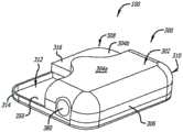
如图1A和图2所示,示例性一次性组件300可以固定到示例性耐用组件200。为此,示例性壳体202包括顶壁204、底壁206a和206b以及侧壁208,其一起限定相对较薄的壳体部分210和相对较厚的壳体部分212。在相对较厚的部分212中形成凹痕214。示例性盖302包括顶壁304a和304b以及侧壁306,其一起限定相对较薄的盖部分308和相对较厚的盖部分310。基板350的一部分未被盖302覆盖,由此限定由围绕基板延伸的壁314界定(也参见图4B)的凹陷部312。当耐用组件200和一次性组件和300以图1A所示的方式彼此固定时,壳体202的相对较厚的部分212将位于一次性组件300的凹陷部312中(其中壁314在凹痕214中)。壳体202的相对较薄的部分210将驻留在盖302的顶壁304b上。盖302还包括与壳体202上的凹陷部216配合的突起316。另外,如下面更详细地讨论的,一次性组件300可以被配置用于不同的药物,诸如不同的药物浓度、不同的药物量、或不同的系统操作模式。As shown in FIGS. 1A and 2 , exemplary
在其他实施方式中,盖302可以被配置为覆盖少于基板350上的所有部件。例如,盖可以被配置为使得磁性电动机转子331和齿轮系332的一部分不在盖下面,而剩余部件在盖下面。在另一些其他实施方式中,可以省略盖302,并且耐用组件200可以被配置为覆盖基板350上的所有部件。在又一些其他实施方式中,在本申请中被称为“耐用”组件的组件可以是一次性的,从而产生完全一次性系统。In other embodiments, cover 302 may be configured to cover less than all of the components on
如在上述美国专利号8,777,901中,以及在2011年11月19日提交的美国专利申请序列号13/300,574和对应美国专利号8,905,972中、以及在2012年5月18日提交的美国专利申请序列号13/475,843和对应美国专利号9,114,208中(这些专利中的每一个都全文以引用方式并入)讨论的,在基板上采用贮存器的可动输注系统可以被配置用于不同类型的使用。例如,一次性组件300可以粘附到患者皮肤,并且可以与可操作地连接到贮存器336的套管(未示出)结合使用,使得系统100可以被部署为“贴片泵”,如图2A所示。另选地,如图2B所示,一次性组件300的基板350可以被配置为将贮存器336可操作地连接至输注器382(例如,通过图1B和图2所示的输注器管和连接器380),使得系统100可以部署为“口袋泵”、“皮带佩戴泵”、或某个其他可穿戴泵。换句话说,使用相同的耐用组件200,用户可以通过简单地选择合适的一次性组件并将一次性组件附接到耐用组件来将系统配置用作“口袋泵”或“贴片泵”。用户还可以通过简单地移除一个一次性组件并将其替换为另一个一次性组件来从一个配置切换到另一个配置。如以下所讨论,连接器380也可以用作填充端口。As in the aforementioned U.S. Patent No. 8,777,901, and U.S. Patent Application Serial No. 13/300,574, filed November 19, 2011, and corresponding U.S. Patent No. 8,905,972, and U.S. Patent Application Serial No., filed May 18, 2012 As discussed in 13/475,843 and corresponding US Pat. No. 9,114,208 (each of which is incorporated by reference in its entirety), movable infusion systems employing reservoirs on a substrate can be configured for different types of uses. For example, the
因此,应当注意,本发明包括包含一次性组件的各种组合的套件,其中一次性组件中的至少两个可以是不同的。另外地或另选地,套件或其他包装可包括各种一次性组件的部件,诸如输注器和/或套管插入器。套件还可包括耐用组件。此类套件中的一次性组件还可以包括下面讨论的检测/识别工具。本套件的部件(例如,各种一次性组件和/或部件的组合)可以存储在公共包装中,其中如果需要的话,针对每个部件具有单独包装并以公共包装提供给用户。此类套件中可提供的其他部件包括但不限于预装载有套管的插入器和清洁拭子。还可以在包括耐用组件的套件中提供再充电器。Accordingly, it should be noted that the present invention includes kits comprising various combinations of disposable components, wherein at least two of the disposable components may be different. Additionally or alternatively, a kit or other package may include components of various disposable assemblies, such as an infusion set and/or a cannula inserter. Kits may also include durable components. Disposable components in such kits may also include the detection/identification tools discussed below. The components of the kit (eg, the various disposable components and/or combinations of components) may be stored in a common package, with individual packaging for each component and provided to the user in a common package, if desired. Other components that may be provided in such kits include, but are not limited to, inserters and cleaning swabs pre-loaded with cannulas. Rechargers are also available in kits including durable components.
除了一次性组件包装和加标签外,不同的一次性组件可包括视觉提示以区分各种一次性组件。例如,具有不同药物浓度或不同药物填充量的一次性组件可以使用针对一次性组件的贮存器和/或基板的不同颜色,或确保一次性组件仅能够附接到正确编程的耐用组件的机械特征。In addition to disposable component packaging and labeling, different disposable components may include visual cues to differentiate the various disposable components. For example, disposables with different drug concentrations or different drug fills may use different colors for the reservoir and/or substrate of the disposable, or mechanical features that ensure that the disposable can only be attached to properly programmed durable components .
在此还应当注意,但出于灌注问题,与输注系统“贴片泵”配置(其可包括耐用组件200和一次性组件300)相关联的分配规程以及与“口袋泵”配置(其还可包括输注器382(参见图2B))相关联的分配规程基本相同。在“贴片泵”配置中,灌注不是必须的,因为相关联套管的体积将是非常小的,并且套管和药物贮存器之间存在直接连接。然而,在“口袋泵”配置中,在开始输送药物之前需要进行灌注以便填充输注器管(图2B)。例如,可能需要20-30μl来填充整个输注器管,并且因此,灌注规程可能涉及将10-15IU的U-500胰岛素快速输送到管。本发明人已经确定有利的是,当系统处于“贴片泵”配置(其中套管被定位成基本上直接从药物贮存器将药物输送到患者)时,防止用户启动灌注规程,因为向患者快速输送10-15IU的胰岛素可不利地影响患者的健康。It should also be noted here, but for perfusion issues, that dispensing protocols associated with the infusion system "patch pump" configuration (which may include a
为了防止此类不期望后果,并在涉及在各种一次性组件(诸如具有包含不同药物、不同浓度的药物、和/或变化量的药物的贮存器的一次性组件)之间进行选择的其他情况下为了用户方便,本发明的至少一些一次性组件可以被设置有基板识别设备,并且本发明的至少一些一次性组件可以被设置有与基板识别设备协作的结构,其方式为使得耐用组件微处理器/控制器可以确定“基板类型”。示例性基板识别工具和方法可以如在以下专利中描述的:上述美国专利号8,777,901;8,905,972;和9,114,208。此外,基板识别可以机械地执行。例如,销或肋可防止某些一次性组件与某些耐用组件的附接。另外地或另选地,某些耐用组件将根本无法与某些一次性组件一起使用。In order to prevent such undesired consequences, and in other methods involving selecting between various disposable assemblies, such as disposable assemblies having reservoirs containing different drugs, different concentrations of drugs, and/or varying amounts of drugs For user convenience, at least some of the disposable components of the present invention may be provided with a substrate identification device, and at least some of the disposable components of the present invention may be provided with a structure cooperating with the substrate identification device in such a way that the durable component The processor/controller can determine the "substrate type". Exemplary substrate identification tools and methods may be as described in the aforementioned US Patent Nos. 8,777,901; 8,905,972; and 9,114,208. Furthermore, substrate identification can be performed mechanically. For example, pins or ribs may prevent the attachment of certain disposable components to certain durable components. Additionally or alternatively, certain durable components will simply not work with certain disposable components.
另选地,患者或临床医生可以诸如经由遥控器对系统进行编程以指示所附接的一次性组件的类型。以诸如这样的方式,患者可以接近用于与单个耐用组件一起使用的各种药物。Alternatively, the patient or clinician can program the system, such as via a remote control, to indicate the type of disposable set attached. In a manner such as this, a patient may have access to various medications for use with a single durable component.
一旦确定了“基板类型”(例如,“贴片泵”一次性组件300相对于其中附接输注器382的“口袋泵”),耐用组件将以适合于所附接的一次性组件的方式或操作模式进行。例如,如果检测到“贴片泵”一次性组件300,则耐用组件控制器将不包括灌注作为输送过程的一部分,并且在一些实施方式中,将防止用户手动实施灌注规程。另一方面,如果检测到“口袋泵”一次性组件,则输送过程可包括输注器管的适当灌注。Once the "substrate type" is determined (e.g., a "patch pump"
无论被配置为“口袋泵”还是“贴片泵”,系统都可以被配置为根据医师通过临床医生的编程单元提供的输送简档来提供基本的药物输送。例如,系统可以包括存储多个输送简档(例如,与24小时输送周期相关联的输送简档、针对诸如睡眠或疾病的特定情况的输送简档等)的程序。每个输送简档指定随时间推移的多个剂量(或泵“操作”),例如,在特定时间的特定数量的剂量或每单位时间的特定数量的剂量。在一些实施方式中,剂量可以是与柱塞335的最小可控位移相关联的体积。系统还可以被配置为响应于来自患者遥控器1000(图2A)的指令而提供推注输送。在糖尿病患者的情况下可响应于高血糖水平测量值,在疼痛管理患者的情况下可响应于疼痛水平的增加,或可响应于某种其他症状而产生推注指令。系统还可以被配置为执行其他功能,诸如响应于来自患者遥控器1000的指令而结束药物输送。Whether configured as a "pocket pump" or a "patch pump," the system can be configured to provide basic drug delivery according to a delivery profile provided by the physician through the clinician's programming unit. For example, the system may include a program to store multiple delivery profiles (eg, delivery profiles associated with a 24-hour delivery cycle, delivery profiles for specific conditions such as sleep or illness, etc.). Each delivery profile specifies a number of doses (or pump "operations") over time, eg, a specific number of doses at a specific time or a specific number of doses per unit of time. In some embodiments, the dose may be the volume associated with the smallest controllable displacement of
本输注泵可以与各种遥控器结合使用。例如,此类遥控器可以用于允许用户向耐用组件200传输指令或促进耐用组件200与用户之间的通信(例如,警报状况消息或与系统100的状况有关的其他消息)。示例性遥控器1000(图2A)可以被配置为促进以下操作中的一个、一些或全部:(1)打开或关闭遥控器1000,(2)将遥控器1000与耐用组件200相关联(或“分配”给耐用组件),(3)获得状态信息(诸如药物水平、电池电量水平和/或警报状况),(4)使耐用组件的警报静音,(5)选择可与耐用组件的警报相关联的选项,诸如警报的类型(可听、可触知、可见或其组合)以及警报的强度/音量,(6)将遥控器1000连接到计算机,例如,以更新遥控器或耐用组件固件、加载和删除存储在耐用组件或遥控器中的输送简档、以及另外对耐用组件或遥控器进行重新编程,(7)选择药物选项,诸如药物浓度,(8)选择并启动存储的药物输送简档,(9)增加和减少药物剂量率,和/或(10)暂停分配操作。用户可以暂停输送以便移除或替换患者应用的结构(例如,一次性组件),进行调整以适应当前或预期的变化身体状况(例如,低血糖、剧烈运动),遵循医师的建议,或出于任何其他原因将耐用组件与身体断开。The infusion pump can be used in combination with various remote controls. For example, such a remote control may be used to allow a user to transmit instructions to
示例性遥控器1000(图2A)可以被配置为基于来自耐用组件200的微处理器223的信息来生成指示符,该指示符例如指示当前分配程序中剩余的时间量、直到下一次一次性组件替换的时间量等。指示符可以是可听的、可见的、可触知的或其组合。出于各种原因,剩余时间指示符可以是有用的。例如,了解下一次一次性组件替换之前的剩余时间允许患者至少部分地基于一天的当前时间和即将发生的事件(例如,旅行或睡眠)来确定在分配程序结束之前的时间替换一次性组件是否更方便。Exemplary remote control 1000 (FIG. 2A) may be configured to generate an indicator based on information from
如上所述,本系统的部件可以被认为是可重复使用的部件,而其他部件可以被认为是一次性部件。在所示的实施方案中,可包括诸如微处理器223和线圈组件224的结构的耐用组件200是可重复使用的,而可包括诸如基板350上的电动机转子331和贮存器336的结构的示例性一次性组件300是一次性的。在其他实施方案中,本系统可以是完全一次性的。As noted above, components of the present system may be considered reusable components, while other components may be considered disposable components. In the illustrated embodiment,
相对于尺寸,示例性输注泵系统100的一些实施方案和以下实施方案可具有以下尺寸:为约35-60mm的长度尺寸;为约30-45mm的宽度尺寸;以及为约8-18mm的整体厚度或高度尺寸。合适的壳体材料包括但不限于弹性模量为0.2-1.0百万psi的塑料或其他材料。With respect to size, some embodiments of the exemplary
示例性耐用组件微处理器和相关联电路;可再充电电池和相关联电池再充电器和再充电方法;电池和再充电管理;温度传感器;以及示例性警报和警报状况在以下专利中更详细地描述:前述美国专利号8,777,901;8,905,972;和9,114,208。Exemplary durable component microprocessors and associated circuitry; rechargeable batteries and associated battery rechargers and recharging methods; battery and recharging management; temperature sensors; and exemplary alarms and alarm conditions are described in more detail in the following patents described in: the aforementioned US Patent Nos. 8,777,901; 8,905,972; and 9,114,208.
现在转到图3A和图3B,示例性耐用组件200可以包括电源,诸如一个或多个电池221、临时电力存储装置(诸如一个或多个电容器222(参见图2和图5B))、控制器(诸如微处理器223)、线圈组件224和霍尔效应传感器225。本领域技术人员将理解,在耐用组件200内包括电动机的线圈组件224和所有其他电子器件减小一次性组件300的成本和复杂性。此外,微处理器223提供向泵100的灵活性以包括诸如用户数据存储、程序、可编程性、可调整性、显示器、按钮、无线通信协议等的特征。耐用组件200也可以被模制有锁定特征,这些锁定特征卡扣到一次性组件300上,但也在一次性组件保持在患者上的适当位置时(在已经暂停药物输送后)或在已经从患者移除整个系统之后允许从一次性组件300移除耐用组件200。Turning now to FIGS. 3A and 3B , an exemplary
电源可以是一个或多个可商购获得的电池,诸如可商购获得的锌-空气电池或锂聚合物电池。电池可以被选择以具有足够的容量以针对某些输送量或输送时间(诸如针对超过400单位的输送的胰岛素)操作系统。任选电力存储装置可以是一个或多个可商购获得的电容器或超级电容器或其他临时存储设备。The power source may be one or more commercially available batteries, such as commercially available zinc-air batteries or lithium polymer batteries. The battery may be selected to have sufficient capacity to operate the system for certain delivered volumes or delivery times, such as for over 400 units of delivered insulin. The optional power storage device may be one or more commercially available capacitors or supercapacitors or other temporary storage devices.
现在转到图4A和图4B,示例性一次性组件300可以包括基板350和部件,诸如贮存器336、在贮存器内并连接到导螺杆334的柱塞335、以及通过齿轮系332机械附接以影响导螺杆驱动齿轮333的旋转的磁性电动机转子331,该旋转致使导螺杆334和柱塞335在贮存器336内平移。在所示的实施方案中,盖302位于这些部件上方。示例性基板350包括用于通过可移除粘合剂盖附接到患者的粘合剂背衬。基板350也可以被模制有基板锁定特征,这些基板锁定特征卡扣到耐用组件200上(诸如模制到每个组件的壳体中的磁体)并且还允许从一次性组件300移除耐用组件200。Turning now to FIGS. 4A and 4B , an exemplary
参考图2和图4B,示例性贮存器336包括具有内表面340的圆筒338,该内表面限定流体存储体积342和椭圆形横截面,但其他形状(诸如圆形)也是可能的,如下面参考图9E所讨论的。具有匹配横截面形状的柱塞335装配在圆筒内并承载流体密封件(诸如但不限于O形环)以将药物密封在存储容积342内。示例性柱塞335可以由例如橡胶形成并且包括三个O形环密封件。贮存器336包括上述连接器380,该连接器可以用于填充贮存器336,或用于为“贴片泵”类型配置附接套管,或用于为“口袋泵”类型配置连接(可能经由一个或多个适当适配器)输注器。柱塞335在圆筒338内移动以改变存储容积342内的药物的体积。贮存器336可以例如被预先填充或用户填充有各种体积的U-500胰岛素以适合患者使用简档。在其他情况下,可以采用较低浓度的胰岛素,诸如U-100胰岛素和U-200胰岛素。可以将插头插入连接器380中以维持无菌环境直到使用。插头可以在使用前由患者移除,或者连接器380可以被配置用于一种用途(密封直到穿透),或其他可能用途,包括在前述美国专利申请序列号15/430,513中更详细描述的那些。Referring to FIGS. 2 and 4B , the
用于与本发明的一次性组件一起使用的附加示例性基板、以及示例性套管设计、药物贮存器和套管之间的流体连接、套管和一次性组件之间的配合(例如,以防止套管相对于基板和患者的轴向移动)、输注器与一次性组件的贮存器的附接、非输送基板的配置和使用、用于附接一次性组件和耐用组件的布置和结构、皮肤粘合剂设计、以及各种阻塞传感器可以在2010年9月24日提交的美国专利申请序列号12/890,207和对应美国专利号8,777,901,以及上述美国专利号8,905,972和9,114,208中描述。Additional exemplary substrates for use with the disposable assemblies of the present invention, as well as exemplary cannula designs, fluid connections between the drug reservoir and the cannula, cooperation between the cannula and the disposable (e.g., in prevention of axial movement of the cannula relative to the base plate and the patient), attachment of the infusion set to the reservoir of the disposable assembly, configuration and use of non-delivery base plates, arrangements and structures for attaching disposable and durable assemblies , skin adhesive designs, and various occlusion sensors can be described in US Patent Application Serial No. 12/890,207 filed September 24, 2010 and corresponding US Patent No. 8,777,901, as well as the aforementioned US Patent Nos. 8,905,972 and 9,114,208.
现在转到图5A至图5C和所示的两件式电动机,耐用组件200的电动机的线圈组件224(和霍尔效应传感器225)位于作为一次性组件300的部分的磁性电动机转子331上方。示例性多极电动机转子331可以是盘形的并且具有9.8mm的外径、5.2mm的内径和0.8mm的厚度。另一个示例性电动机转子可以具有11mm的外径、5mm的内径和1.2mm的厚度。这种类型的多极电动机转子每片的成本通常不到5美分,从而有助于控制一次性组件200的总成本。在所示的实施方案中,电动机转子331也平行于基板350,即,电动机转子旋转轴线垂直于基板。微处理器223通过顺序地激励电动机线圈组件224的线圈以在电动机线圈组件224和电动机转子331之间产生电磁转矩耦合来引导电动机转子331的旋转。转子极相对于旋转磁场发生器(线圈组件224)的位置/取向通过反EMF、旋转编码器、霍尔效应传感器225(图5A)等来测量。例如,安装在线圈绕组上的霍尔效应传感器可用于向微处理器供应计数、转速计信号或转子位置,从而允许对转子速度进行低成本闭环控制。这种类型的无刷电动机通常效率为85-90%或更高,并且运行非常凉爽。尽管在构造中可以有变化,但图5A至图5C所示的面对面的定子线圈和平坦转子板提供了紧凑设计。此外,可以使用更多的线圈和/或霍尔效应传感器。Turning now to FIGS. 5A-5C and the two-piece motor shown, the coil assembly 224 (and Hall effect sensor 225 ) of the motor of the
如从图6中可以最好地看出,间隙240在电动机线圈组件224和电动机转子331之间。在所示的实施方式中,间隙240中的一些或全部可以由壳体202和盖302的部分(即壳体底壁206a和盖顶壁304b)限定(和占据)。在其他实施方式中,电动机线圈组件224和电动机转子331之间的间隙240可以由耐用组件壳体的仅一部分占据,或者由一次性组件盖的仅一部分占据,或者根本没有结构并且可以仅是气隙。由电动机线圈组件224和电动机转子331之间的距离限定的间隙的尺寸通常为约0.5mm至2.0mm。这样,在耐用组件200和一次性组件300之间没有齿轮啮合或其他机械连接。并且如前所述,所有电子器件可以定位在耐用组件200内,其中一次性组件300所需的能量通过电磁转矩耦合来传递,该电磁转矩耦合是没有来自耐用组件200的直接机械耦合或电接触的耦合。该示例性设计提供了附加优点,即,使防水或至少抗水是相对简单的。As best seen in FIG. 6 ,
如上所述,电动机转子331的旋转驱动齿轮系332,从而致使导螺杆驱动齿轮333的旋转,该旋转继而影响导螺杆334和附接到导螺杆334的柱塞335的平移。以这种方式,当由耐用组件200供应的电磁能量被转换成在一次性组件300内推进柱塞335的机械力时,产生电磁生成的转矩。棘轮(未示出)或其他类似设备可以用于防止齿轮系332的反向驱动。当柱塞335被驱动通过贮存器336时,与齿轮和电动机转子的精确移动相对应地精确分配药物。在整个齿轮系、导螺杆驱动齿轮、导螺杆和柱塞都永久包含在一次性组件300中的情况下,与一次性组件300分离之前,无需将任何柱塞组件缩回到耐用组件200中。因此,该示例性设计(以及下面的那些)的另一优点是极大减小的能量消耗,其允许例如使用一个或多个一次电池作为电源。As described above, rotation of the
现在将描述示例性系统100的使用。在最基本的水平上,患者对示例性输注泵系统(例如,图1A至图2B中的系统100)的使用涉及获得新的一次性组件300,将一次性组件连接到耐用组件200,从基板粘合剂层剥离衬里,获取皮下进入,以及启动药物输送操作。在一些情况下,使用可能涉及附加步骤,诸如将套管附接到一次性组件的连接器380上并在必要时移除套管帽。下面描述本系统的基本操作的各个方面。每次部署系统时,系统的操作不一定都需要所有步骤,并且一些步骤的顺序可能会改变。下面也经由流程图(图8)在用作贴片泵的上述耐用组件200和一次性组件300的示例性上下文中讨论操作。然而,该讨论同样适用于其他贴片泵实施方式,诸如图10A至图10H所描述的,以及具有微小变化的口袋泵实施方式。而且,除非另外指出,否则由耐用组件200执行的动作和确定由耐用组件微处理器控制,并且出于简洁的目的,对控制器的进一步引用受到限制。Use of the
参考图8,本系统的使用可以涉及从耐用组件中移除一次性组件以及替换一次性组件。这可能在以下情况下发生:当药物贮存器为空(如在美国专利申请序列号12/890,207和对应美国专利号8,777,901中描述)(步骤S101),并且在遥控器1000上呈现“替换一次性组件”消息或警报(步骤S102)时,或当来自耐用或一次性组件的蜂鸣器或其他警报(可听的、可触知的、可见的或其组合)可以发出信号表示需要一次性组件替换时。另选地,耐用组件控制器可以从遥控器1000接收用户发起的“替换一次性组件”信号(步骤S103)。出于各种原因,用户可能期望在药物贮存器为空之前替换一次性组件,诸如例如,为了适应用户的睡眠或旅行计划,当药物表现出效力损失时,当出现分配问题时,或由于药物的固定改变。Referring to FIG. 8, use of the present system may involve removing disposable components from durable components and replacing disposable components. This may occur when the drug reservoir is empty (as described in U.S. Patent Application Serial No. 12/890,207 and corresponding U.S. Patent No. 8,777,901) (step S101 ), and "Replace Disposable components" message or alarm (step S102), or when a buzzer or other alarm (audible, tactile, visible, or a combination thereof) from a durable or disposable component may signal that a disposable component is required when replacing. Alternatively, the durable component controller may receive a user-initiated "replace disposable component" signal from the remote controller 1000 (step S103). For various reasons, the user may desire to replace the disposable assembly before the drug reservoir is empty, such as, for example, to accommodate the user's sleep or travel schedule, when the drug exhibits a loss of potency, when a dispensing problem occurs, or due to fixed change.
然后,用户可以取决于药物要求可能从冰箱中的存储装置获得新的预填充一次性组件300,或者可以随后获得新的一次性组件并用药物填充一次性组件中的贮存器(步骤S104)。另选地,如下所述,可以在将一次性组件300附接到耐用组件200之后填充贮存器。然后可以从皮肤移除耐用组件200和一次性组件300,进行分离,并且丢弃已使用的一次性组件300(步骤S106和S107)。The user may then obtain a new pre-filled
接下来,可以将新的一次性组件300附接到耐用组件200(步骤S109)。在具有用户填充的贮存器的一次性组件的情况下,如果先前未填充,则用户然后将药物从注射器注入贮存器中(步骤S112)。可以注入药物直到贮存器已满,或者用户可以选择从注射器引入特定量的药物。由于可能将未知量的药物注入用户填充的贮存器中,因此柱塞推动器归零规程(步骤S113)(诸如在美国专利申请序列号12/890,207和对应美国专利8,777,901中所述)然后可以由用户发起,或者可以是泵操作的自动方面。如果归零规程的结果是负的,则可以移除并丢弃一次性组件300,可以附接并填充新的一次性组件,并且可以重复归零规程。稍有改变的归零规程将在下面详细介绍。Next, a new
在用户填充的或预填充的配置中,用户然后应清洁将一次性组件300的基板350将粘附到的皮肤表面S(图7以及图8的步骤S116)。然后,用户剥离基板粘合剂衬里以暴露基板粘合剂层(步骤S117),并且移除使用前拉动插头PBUP 517(如果存在)(步骤S118)。根据需要或期望,可能以相反的顺序执行这最后两个步骤S117和S118。In a user-filled or pre-filled configuration, the user should then clean the skin surface S to which the
可以将包括耐用组件200和一次性组件300的系统100定位在选定身体位置上方,并且轻按压该系统以将粘合剂层粘附到皮肤表面S。一旦已经粘附系统,就可以如下面更详细描述的那样致动插入器(步骤S119),以将套管的端部定位在皮肤下方约6mm处。最后,如果需要,可以使用遥控器1000来发起特定药物输送操作(步骤S120)。输送操作可以遵循预定的输送简档(例如,特定的基础速率、一系列时间间隔的推注输送、或其某种组合),其等于根据简档输送药物所需的特定速率和时间下的电动机转子旋转。另选地,简档可以由用户通过遥控器1000输入并且由耐用组件微处理器存储。例如,遥控器可以存储患者可从中选择的许多不同的输送简档和推注输送。例如并取决于药物,此类简档可以对应于预期剧烈运动的日子、不期望剧烈运动的日子、疼痛加剧的发生率等。另选地或除此之外,存储在耐用组件微处理器中的简档可以由临床医生的编程单元来设置。在这种情况下,如在不同的一次性组件300被设置有不同的指定输送速率的情况下,可能不需要遥控器来发起例如基础输送。The
上面的讨论也适用于如图2B所示的“口袋泵”系统的使用。例如,上述规程中的细微变化包括:使用输注器382代替套管,可能经由适配器(其可随输注器382的类型而变化)将输注器附接到连接器380,以及灌注输注器382的管。The above discussion also applies to the use of the "pocket pump" system as shown in Figure 2B. For example, slight variations in the above procedure include using an infusion set 382 instead of a cannula, attaching the infusion set to the
在图9A中大体由附图标记100a表示的另一个示例性可动输注系统包括耐用组件200a和一次性组件400。系统100a基本上类似于系统100。然而,在此,顶壁的相交部基本上是线性的。另外,一次性组件400具有与耐用组件200a上的对应突起216a匹配的凹陷部316a。突起216a和凹陷部316a位于已组装系统100a的外周边。Another exemplary mobile infusion system, generally indicated by
在图9B和图9C中更详细地示出的示例性耐用组件200a可以包括:壳体202a、一个或多个电池或其他能量供应221a、一个或多个电容器或其他能量存储装置(未示出)、微处理器(未示出)、以及包括一个或多个霍尔效应传感器(未示出)的线圈组件224a。在图9D和图9E中更详细地示出的示例性一次性组件400可以包括基板450,其支撑诸如以下的部件:磁性电动机转子431、包括导螺杆驱动齿轮433的齿轮系432和附接到柱塞组件435的导螺杆434,该柱塞组件定位在具有圆形横截面的药物贮存器436中。电磁电动机转子431可以通过齿轮系432机械地附接以影响导螺杆驱动齿轮433的旋转,该旋转致使导螺杆434和柱塞435在贮存器436内平移。贮存器436可以例如预填充有U-500胰岛素或U-100胰岛素或其他浓度的胰岛素以适合不同的患者使用简档,或者可以是用户可经由填充端口415填充的。贮存器出口438与贮存器436流体连通。一次性组件400可以固定到耐用组件200a,如图9A所示,并且如在美国临时专利申请序列号62/057,273、对应美国专利申请序列号14/869,906和对应美国专利公开号2016/0089491中进一步描述。The exemplary
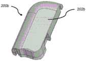
在图10A和图10B中大体由附图标记100b表示的另一个示例性可动输注系统包括耐用组件200b和一次性组件500。系统100b基本上类似于系统100和100a。在此,顶壁和内壁的相交部在一些地方是线性的,并且在其他地方是弯曲的。在图10A和图10B还示出了附接有粘合剂背衬503的粘合剂垫501、填充端口515、使用前拉动插头(PBUP)517和套管触发按钮520。这些特征将在下面更详细地描述。Another exemplary mobile infusion system, generally indicated by the
在图10C至图10E中更详细地示出的示例性耐用组件200b可以包括:壳体202b、蜂鸣器或其他警报设备227、一个或多个电池或其他能量供应221b、微处理器(未显示)、以及包括一个或多个霍尔效应传感器225b的线圈组件224b(其用作电动机定子)。在该实施方案中,能量供应221b是可再充电电池,诸如可再充电锂电池,其具有足够的电力以连续地驱动电动机而无需电容器或其他附加的能量存储设备。如前所述,示例性耐用组件微处理器和相关联电路;可再充电电池和相关联电池再充电器和再充电方法;电池和再充电管理;温度传感器;以及示例性警报和警报状况在以下专利中更详细地描述:前述美国专利号8,777,901;8,905,972;和9,114,208。The exemplary
返回图10E,线圈组件224b围绕耐用壳体部分228定位,该耐用壳体部分被配置为装配在一次性壳体部分528(图10F)上方,该一次性壳体部分继而装配在磁性电动机转子531(图10G)上方。在这种两件式电动机中,电动机的线圈组件224b处于耐用组件200b中,并且围绕作为一次性组件500的部分的电动机转子531定位。霍尔效应传感器225b定位在耐用组件200b中的线圈组件224b上方。在此配置中,电动机线圈组件224b与电动机转子531之间存在间隙。在所示的实施方式中,间隙中的一些或全部可以由壳体部分(例如,耐用壳体部分228和一次性壳体部分528)限定(和占据)。在其他实施方式中,电动机线圈组件224b和电动机转子531之间的间隙可以由耐用组件壳体的仅一部分占据,或者由一次性组件盖的仅一部分占据,或者根本没有结构并且可以仅是气隙。由电动机线圈组件224b和电动机转子531之间的距离限定的间隙的尺寸通常为约0.5mm至2.0mm。这样并且如前所述,在耐用组件200b和一次性组件500之间没有齿轮啮合或其他机械连接。同样如前所述,所有电子器件可以定位在耐用组件200b内,其中一次性组件500所需的能量通过电磁转矩耦合来传递,该电磁转矩耦合是没有来自耐用组件200b的直接机械耦合或电接触的耦合。这些示例性设计提供了附加优点,即,使防水或至少抗水是相对简单的。Returning to FIG. 10E ,
示例性电动机转子531可以是2极、圆柱形、稀土(诸如钕)转子,其在直径上被磁化,具有5mm的直径和5mm的高度。其他合适的电动机转子可以是更大的或更小的,或者是多极的。这种类型的电动机转子每片的成本通常为约5美分,从而有助于控制一次性组件500的总成本。微处理器(未显示)通过顺序地激励电动机线圈组件224b的线圈以在电动机线圈组件224b和电动机转子531之间产生电磁转矩耦合来引导电动机转子531的旋转。转子极相对于旋转磁场发生器(线圈组件224b)的位置/取向通过反EMF、一个或多个旋转编码器、一个或多个霍尔效应传感器225b等来测量。例如,安装在线圈绕组224b上方的霍尔效应传感器225b可用于向微处理器供应计数、转速计信号或转子位置,从而允许对转子速度进行低成本闭环控制。如前所述,这种类型的无刷电动机有效且运行非常凉爽。尽管在构造中可以有变化,但图10D至图10G所示的配置提供了紧凑设计。An
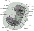
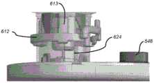
在图10F和图10G中更详细地示出的示例性一次性组件500可以包括基板550,其支撑诸如以下的部件:上述磁性电动机转子531和齿轮系532。齿轮系532附接到定位在药物贮存器536中的柱塞组件535。柱塞组件535包括柱塞推动器535a和柱塞535b以及其他部件。磁性电动机转子531可以通过齿轮系532机械地附接以影响柱塞推动器535a(和柱塞535b,当附接到柱塞推动器535a时)在贮存器536内的平移。贮存器536可以例如预填充有U-100胰岛素或U-500胰岛素或其他浓度的胰岛素以适合不同的患者使用简档,或者可以是用户可通过填充端口515填充的。贮存器出口配件548与贮存器536流体连通。套管触发按钮520在被按压时致使定位在贮存器出口配件548上方的触发连杆547的旋转,从而触发套管的插入(如下文更详细地描述)。贮存器出口配件548由药品相容性材料制成,诸如但不限于聚丙烯、环烯烃聚合物(COP)或聚乙烯。套管触发按钮520和触发连杆547可以由坚固、轻质的材料制成,诸如聚碳酸酯、尼龙、乙缩醛
如图10G中最佳所示,示例性一次性组件500的齿轮系532与上述实施方案中的齿轮系略有不同。在该实施方案中,齿轮系532包括由蜗杆螺钉533a和蜗轮533b组成的蜗杆驱动器,以及还包括细间距导螺杆(未示出)和导螺杆螺母534a。蜗轮533b经由包围导螺杆的导螺杆螺母534a耦合到导螺杆。导螺杆螺母534a上的突起534b与蜗轮533b内部的凹陷部(未示出)相对应,并且导螺杆螺母534a内部的螺纹部分(未示出)与由导螺杆螺母534a包围的导螺杆上的螺纹配对。齿轮系532的配置防止了向后驱动,从而消除了对离合器或其他锁定机构的需要。用于齿轮系532的部件的合适材料包括但不限于不锈钢或高强度塑料,诸如尼龙、乙缩醛
也如图10F所示,示例性一次性组件500与上述实施方案的不同之处也在于,柱塞组件535除了柱塞535b之外还包括柱塞推动器535a。在上述美国专利号8,777,901中描述了示例性输注泵,该输注泵包括具有柱塞(与以柱塞推动器形式的流体位移设备结合)的贮存器。在具有用户填充的贮存器的一次性组件的情况下,用户可以用药物完全填充贮存器以达到容量,或者用户可以选择引入较少的药物并且不完全填充贮存器。如前所述,由于可能将未知量的药物注入用户填充的贮存器中,因此诸如在美国专利号8,777,901中描述的柱塞推动器归零规程可以是用户发起的,或者可以是泵操作的自动方面。在任何药物分配之前,推动器归零规程精确地确定和/或设置柱塞推动器535a在其与柱塞535b接合之前必须精确行进多远,从而允许进行计算以确定贮存器中的药物量并因此确定清空时间的估计值以及对一次性组件替换的需求。As also shown in FIG. 1OF, the exemplary
图10G示出了在将任何药物引入贮存器536中之前的柱塞组件535。此时,并且直到推动器归零完成,柱塞535b在贮存器536内自由浮动,并且PBUP 517必须就位,如图10H所示。柱塞推动器535a始终附接到导螺杆534a并且以完全缩回位置开始。当药物经由填充端口515引入贮存器536中时,柱塞535b被推向柱塞推动器535a。如果贮存器被填充以达到容量,则柱塞535b将被推动成与柱塞推动器535a进行接触,从而致使推动器535b上的钩537(或其他合适的附接方法)与推动器535b接合并且将其永久地锁定到柱塞推动器535a。如果贮存器536没有被填充以达到容量,则柱塞535b将被定位在贮存器536内的某个未知点处,直到柱塞归零完成。一旦用户已经将药物引入贮存器536中,柱塞归零就由用户发起或者可以是泵操作的自动方面(例如,当一次性组件500附接到耐用组件时)。当发起推动器归零规程时,电动机推进柱塞推动器535a,直到它接触推动器535b,并且它们通过柱塞钩537或其他合适的附接方法锁定在一起,如前所述。贮存器536和柱塞535b可由环烯烃聚合物(COP)、聚丙烯或其他药物相容性聚合材料制成。用于柱塞推动器535a的合适材料包括但不限于不锈钢、COP、尼龙和聚碳酸酯。FIG. 10G shows plunger assembly 535 prior to introducing any drug into
如前所述,当来自药筒536的流被PBUP 517阻塞时,将执行归零规程。给定可能存在与药筒制造相关联的公差和药物填充的变化,柱塞推动器535a在其与柱塞535b接合并开始将药物驱出贮存器之前必须从其初始原始位置行进的距离可以变化。在微处理器控制下,电动机将柱塞推动器535a推进成与柱塞535b接合,从而致使增加的流体路径压力。对霍尔效应传感器225b、编码器、或其他监测/感测设备进行采样以确定在推进推动器535a时何时发生电动机失速。来自霍尔效应传感器225的信号的缺乏证明电动机没有转动。电动机失速被认为是由于液压锁定引起的,并且因此指示柱塞推动器535a与已插装的药筒536的柱塞535b接合。如在上述美国专利号8,777,901中详细描述的,规程可以采用两个或更多个速度来推进推动器。而且,可能以受控转矩或有限力来推进推动器535a,使得电动机将以可能最少量的力发生失速以获得可靠结果,以便减小系统(例如,轴承和电池)上的负荷。如上所述,已知柱塞推动器535a在接合柱塞535b之前行进的距离允许计算药物体积和直到将需要一次性组件500替换的估计时间。As before, when the flow from the
插入机构600是4状态系统。图10A至图10H示出了处于其第一状态的插入机构600:在患者移除PBUP 517(图10H)并且推动套管触发按钮520(图10G)以插入套管之前的准备击发位置。在这种状态下,PBUP 517被定位成阻塞来自贮存器536的流体路径(图10G),并且套管载体612被保持在套管密封件630上方并与该套管密封件间隔开(图10H),如下文进一步描述。在这种状态下,并且如图10G中最佳所示,上述柱塞推动器归零规程可以将推动器535a推进成与柱塞535b接触,从而对贮存器536稍微加压,而不会将药物注入到患者中。如图10H中最佳所示,在密封环631和PBUP 517的外表面之间形成密封,从而允许柱塞推动器归零规程所需的压力。
为了防止套管触发按钮520的意外按下,可以将按钮防护件插入按钮520与一次性组件500的壳体之间。例如,如在图10A和图10B中最佳所示,PBUP 517可以包括触发按钮防护件518,其从输注系统100b的下侧向上弯曲通过粘合剂垫501中的开口并装配在套管触发按钮520下方。在按钮防护件518就位的情况下,不可能按下触发按钮520以发起套管插入。PBUP 517可以由COP、聚丙烯、或其他类似的药品相容性材料制成。按钮防护件518可以由与PBUP 517相同的材料制成(并且它们可以是一件),或者它可以由不同的材料制成,诸如聚碳酸酯。To prevent accidental depression of the
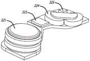
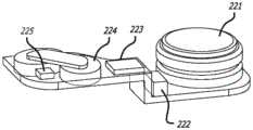
现在转到图11A至图11D,示例性一次性组件500包括基板550、贮存器出口配件548和插入机构600,为清楚起见,在其中套管触发按钮520和触发连杆547被移除的情况下示出。从这些图和先前的图中可以看出,输注系统100b(以及附图所示的所有输注系统)非常紧凑,从而限制可用的弹簧能量和可用于套管和贮存器之间的流体互连的体积。流体连接必须极其可靠并且通过很少能量来创建。因此,插入机构600必须极其有效且可靠。Turning now to FIGS. 11A-11D , an exemplary
图11A至图11D示出了处于其第二状态的插入机构600:PBUP 517已经被移除并且插入机构600准备好击发。来自贮存器536(图10G)的流体路径向大气开放,并且在套管插入之前排出任何残余压力。11A-11D show the
简单来说,在移除PBUP 517之后,当患者推动套管触发按钮520时,插入机构600首先致使套管针647和套管641(在图11D中最佳所示)从一次性组件500突出(其为状态三,图12A和图12B所示),并且然后致使套管针647缩回到插入机构600中,从而将套管641留在适当位置(其为状态四,图13A至图13D所示)。包括具有尖锐远侧尖端的伸长杆的套管针647可以由金属(诸如不锈钢)或其他相对刚性的生物相容性材料(诸如刚性塑料、陶瓷、或其他刚性生物相容性材料)制成,并且用于穿透皮肤并穿透短距离到肉体中,以便为套管641形成通道。套管641可以由诸如
如图11A最佳所示,插入机构600包括主插入弹簧610和支撑在引导壳体620上的套管载体612。还参考图11B至图11D,插入机构600还包括套管针载体674、套管针密封件680、套管针缩回弹簧682、套管密封件630和套管密封件保持器634。如以下进一步描述的,这些部件提供了通过低套管插入力的高度有效的套管密封和高度可靠的药物密封。As best shown in FIG. 11A , the
图11B示出了插入机构600,其中主插入弹簧610和引导壳体620被移除。在图11C中,主插入弹簧610被移除并且引导壳体620是半透明的。图11D是图11C的部件的截面图。主插入弹簧610可提供约7mm的行程,其中起始力为约15牛(N)且终止力为约7N,并且可以由例如直径为0.75mm的乐器用钢丝制成,其中有6匝且外部尺寸为13.25mm。套管针缩回弹簧682可提供约7mm的行程,其中起始力为约4N且终止力为约1N,并且可以由例如直径为0.5mm的乐器用钢丝制成,其中有6匝且外部尺寸为3mm。引导壳体620和套管密封件保持器634可以由高强度塑料(诸如尼龙、乙缩醛
如以上所述,图11A至图11D示出了在患者推动套管触发按钮520以致使套管载体612将套管641驱动到插入位置中之前的处于状态二(即准备击发位置)的插入机构600。在插入之前,套管载体612被支撑在引导壳体620的支撑凸缘622上(在图11D中最佳所示),该支撑凸缘继而将主插入弹簧610保持在压缩状态。应当注意,引导壳体620在套管插入期间不移动。As noted above, FIGS. 11A-11D show the insertion mechanism in state two (ie, the ready-to-fire position) before the patient pushes the
当用户按压套管触发按钮520时,其推动触发连杆547,从而致使触发连杆547旋转。当触发连杆547旋转时,它逆时针推动套管载体612,从而致使套管载体612滑出引导壳体620的支撑凸缘622,并且致使载体突片613与引导壳体狭槽624对准(如图11A和图11C所示)。一旦套管载体612不再由引导壳体凸缘622支撑,套管载体612就不再能够抵抗主插入弹簧610的力,并且主插入弹簧610中包含的弹性能量被转换成运动。主插入弹簧610然后向下驱动具有附接的套管641的套管载体612、具有附接的套管针647的套管针载体674、套管针密封件680和套管针缩回弹簧682。当这些部件向下移动时,延伸稍微超出套管641的远侧端部的套管针647的尖锐远侧尖端穿透患者的皮肤,并且插入围绕套管针647的套管641,因此套管641的端部位于患者皮肤表面下方约6mm处。此时,如图12A和图12B所示,插入机构600处于状态三。When the user presses the
如在图11B、图12B和图13B中最佳所示,套管载体612和套管针载体674包括用于在套管插入之前和期间将它们锁定在一起的特征。套管针载体674包括装配在套管载体612上的锁定凸台615下方的锁定凸缘675。当套管载体612和套管针载体674被锁定在一起时,套管针缩回弹簧682被保持在压缩状态。此外,套管针载体674包括接触套管载体612上的锁定凸台壁617的锁定凸缘壁677。这些壁确保套管针载体674仅与套管载体612一起逆时针移动,因此套管针载体的锁定凸缘675不会意外地从套管载体的锁定凸台615下方滑出并且无意中触发套管针647的穿透。As best shown in FIGS. 11B , 12B and 13B ,
一旦套管载体612和套管针载体674旋转以开始套管插入并开始朝向患者向下移动,套管针载体突片678的成角度边缘679就接触密封件保持器634上的拐角635。当套管针载体674向下移动时,拐角635和成角度边缘679之间的接触致使套管针载体674在套管插入期间越来越逆时针旋转。当套管载体612向下移动时,载体突片613被定位在引导壳体狭槽624内(如图11A和图11C所示),从而允许套管载体612向下滑动,同时防止套管载体612的附加旋转。随着套管针载体674进一步逆时针旋转,套管针载体的锁定凸缘675从套管载体的锁定凸台615下方滑出。
图12A和图12B示出了处于状态三的插入机构600:图12A示出了在释放套管针载体674的瞬间并且在套管针缩回弹簧682向上驱动套管针载体674和套管针647之前的完全击发的主插入弹簧610、完全向下的套管载体612、以及完全插入的套管641。(如图所示,以约90度刺穿皮肤,并且套管端部位于皮肤表面下方约6mm处。)图12B示出了相同的瞬间,其中主插入弹簧610和引导壳体620被移除。该视图示出了套管针载体的锁定凸缘675从套管载体的锁定凸台615下方释放的时刻。12A and 12B show the
一旦套管针载体的锁定凸缘675从套管载体的锁定凸台615下方释放(这也是套管641被完全插入,并且插入机构600处于状态三的时刻,如图12A和图12B所示),套管针载体674不再能够抵抗套管针缩回弹簧682的力。套管针缩回弹簧682中包含的弹性能量被转换成运动,并且套管针缩回弹簧682向上驱动具有附接的套管针647的套管针载体674。当套管针载体674向上移动时,套管针647从患者移除并缩回到插入机构600中,从而将套管641留在被插入。这是状态四,如图13A至图13D所示。Once the locking
图13A是示出完全击发的插入机构600以及完全缩回的套管针647的截面图。图13B示出了完全击发的插入机构600的更多细节,其中主插入弹簧610和引导壳体620被移除。这是在患者使用示例性可动输注系统100b时的插入机构600的部件的位置。药物路径在图13A和图13C中最佳所示。概括地说,药物从贮存器(未示出)流到出口配件548,流到套管密封件630中,流过套管载体612中的通道614,流过套管针密封件680,并且流到套管641中以输送给患者。13A is a cross-sectional view showing the
图13C和图13D最佳示出了形成在套管载体612与套管密封件630的上密封环和下密封环631之间的高度有效的径向压缩液压密封件。上密封环和下密封环631分开约2.5mm。套管密封件630到密封环631的小接触区域的渐缩集中了表面应力,其中密封环631接触套管载体612以提供良好密封。附加的上密封环和下密封环是有可能的,但可增加空间要求。为了增强密封环631处的密封,主插入弹簧610在套管载体612上施加力,从而保持其保持向下抵靠基板550并致使套管载体内表面616在套管密封件630的顶表面上推动,如下文所详述。13C and 13D best illustrate the highly effective radial compression hydraulic seal formed between the
在从插入的状态二到状态三的过渡期间,在套管载体612的底表面接触基板550之前,套管载体的内表面616开始接触套管密封件630的顶部。当达到状态三时,保持套管载体612的底表面抵靠基板550,并且从上方压缩套管密封件630。高能量的主插入弹簧610改善密封可靠性,并且套管密封件630在其被压缩时充当缓冲器,从而有助于耗散插入的能量。来自主插入弹簧610的击发的残余能量不会被浪费或被转换为用户可感知的噪音和感觉,而是从动能转换为套管密封件630的增强的径向压缩。During the transition from inserted state two to state three, the
此外,套管载体内表面616和套管密封件630的顶表面之间的接触形成辅助面密封件。在状态三中,主插入弹簧610以约7-10N的力继续向下推动在套管载体612上。除了维持在上密封环631处的密封之外,散布在套管密封件630的顶表面上的该力导致能够密封约3巴的流体密封。Additionally, the contact between the sleeve carrier
为了进一步增强此密封,密封件保持器634提供了径向支撑,从而用作固定背衬环/夹具,增加了围绕套管密封件630的径向压缩。甚至进一步增强密封,套管载体612通过在套管密封件630上的夹紧力提供附加径向压缩,从而用作附加背衬环/夹具。来源于主插入弹簧610的7-10N残余力导致套管密封件630上的向下(轴向)压缩,从而致使套管密封件630的径向变形,进一步改善在套管载体612和密封环631之间形成的密封。在状态三中,由于套管密封件630被密封件保持器634和套管载体612径向约束,因此套管密封件630的轴向压缩致使密封件630的径向变形,从而增加密封环631上的密封力。所有这些导致高度有效和可靠的液压套管密封。To further enhance this seal,
现在转到图13C,药物路径还包括压缩类型配件690,该压缩类型配件由密封件保持器634的夹紧部分636形成,该夹紧部分将套管密封件630的套圈632向下夹紧到出口配件548的倒钩549上。作为替代方案,可以利用单独的部件来输送由密封件保持器634的夹紧部分636提供的夹紧力。此外,套管密封件630的套圈632和出口配件548的倒钩549可以是分开的套圈和倒钩部件,但会沿药物路径引入附加部件接口,其各自需要附加密封特征。在所示的配置中,套管密封件630密封套管641,通过在被套管载体612撞击时压缩来吸收击发期间的能量,并且有助于用套管632密封贮存器。Turning now to FIG. 13C , the drug pathway also includes a compression type fitting 690 formed by the
如图13D中最佳所示,药物接下来流过套圈632,流过套管密封件630,流过套管载体612中的通道614,流过套管针密封件入口681,流过套管针密封件通道683,以及流过套管641以输送给患者。从比较图11D、图12A和图13A中可以看出,套管针密封件680在插入过程之前、期间和之后保持在套管载体612内的一个位置,并且在患者使用示例性可动输注系统100b期间保持在该位置中。套管针密封件680包括侧壁密封环684和基部密封环686。侧壁密封环684防止药物泄漏到套管载体612中并最终泄漏到示例性可动输注系统100b中。基部密封环686防止从套管641周围泄漏,并且确保从套管针密封件入口681流动并通过套管针密封件通道683的药物被引导到套管641中。图13D示出了一对侧壁密封环684和一对基部密封环686,但是附加密封件可以用于附加泄漏保护。As best shown in Figure 13D, the drug next flows through
插入机构600通过低插入力提供了高度有效、高度可靠的药物密封(全部在紧凑空间中)。供应给插入套管641的能量由主插入弹簧610提供,并且需要足以(a)允许套管针647快速且干净地刺穿患者的皮肤以进行套管插入,(b)克服在套管载体612的表面抵靠套管密封件630的表面和密封件保持器634的表面移动期间的摩擦力,以及(c)产生压缩力和径向力,从而形成可靠的药物密封。多余能量被套管密封件630的压缩吸收,这会使套管密封件630径向扩展,从而增加由密封环631抵靠套管载体612的表面施加的径向力以及由套管密封件630抵靠密封件保持器634施加的径向力,如下文更详细地解释。当前还更详细描述了能量要求和支出。The
在操作期间,当插入机构600从状态二过渡到状态三时,施加在套管密封件630上的径向压缩力增加。当套管载体612开始向下移动时,它首先接触上套管密封环631,并且通常开始捕获并围绕套管载体612和密封件保持器634的表面之间的套管密封件630。密封件保持器634用作固定背衬环,从而为套管密封件630提供径向支撑,有助于施加到套管密封件630的径向夹紧力。然而,在一些替代方案中,如瞬时说明的那样,在密封件保持器634与套管密封件630之间可能存在小间隙,直到套管密封件630被向下压缩并径向扩展。当套管载体612继续向下移动时,施加到套管密封件630的径向力增加,因为接触量以及因此径向力继续在以下之间增加:(i)套管载体612和套管密封环631的表面,(ii)密封件保持器634和套管密封件630,以及(iii)在一些替代方案中,套管载体612和密封件保持器634的表面。关于下一个实施方案,在从状态二到状态三的过渡期间,套管载体612和密封环631之间的接触也在下面更详细地描述。During operation, as
当套管载体612继续向下移动时,在套管密封件630的顶表面与载体内表面616之间进行接触(参见图11D和图13D)。如上所述,这种初始接触在套管载体612仍向下移动时发生。因此,当套管载体612继续向下移动时,载体内表面616在套管密封件630上施加增加的向下力,并且在其这样做时,套管密封件630随着套管载体612继续移动而被越来越多地压缩。当载体内表面616从上方越来越多地推动在套管密封件630上时,套管密封件630越来越径向扩展,从而在以下之间产生附加径向压缩力:(i)密封环631和套管载体612以及(ii)套管密封件630和密封件保持器634。套管密封件630最终可以径向扩展例如0.5mm。(在密封件保持器634和套管密封环630之间存在小间隙的替代方案中,随着套管密封件630由于套管密封件630被载体内表面616向下压缩而径向扩展,该间隙减少直到其被消除。)此外,如上所述,套管载体内表面616和套管密封件630的顶表面之间的接触形成辅助面密封件。这样,通过以下实现了高度有效和高度可靠的套管密封:(1)在套管载体内表面616和套管密封件630的顶表面处形成的该面密封件,(2)密封环631和套管载体612之间的接触,(3)由密封件保持器634施加在套管密封件630上的径向夹紧力,(4)由套管载体612施加的增加的径向夹紧力,该套管载体用作附加背衬环(除了密封件保持器634之外)并提供套管密封件630的增加的径向压缩,以及(5)由套管载体612在套管载体内表面616处施加在套管密封件630的顶部上的向下力,其使套管密封件630径向扩展并且增加(a)由密封环631抵靠套管载体612的表面施加的径向力以及(b)由套管密封件630抵靠密封件保持器634施加的径向力。As the
在图14A至图14F中示出了用于可动输注系统的一次性组件的插入机构600a的另一个示例性实施方案。该实施方案使用了在状态三下接合套管密封件630a的可移动背衬结构(套管载体612a的部分),然而上述实施方案除了可移动背衬结构(套管载体612的部分)之外还使用了固定背衬环(密封件保持器634)。如下面进一步描述的,该实施方案还提供了通过低套管插入力的高度有效的径向压缩密封和高度可靠的药物密封。Another exemplary embodiment of an
如上,供应给插入套管641a的能量由主插入弹簧610a提供(参见图14B和图14F)并且需要足以(a)允许套管针647a快速且干净地刺穿患者的皮肤以进行套管插入,(b)克服在套管载体612a表面抵靠套管密封件630a表面的移动期间的摩擦力,以及(c)产生压缩力和径向力,从而形成可靠的药物密封。如上,多余能量被套管密封件630a的压缩吸收,这会使套管密封件630a径向扩展,从而增加由密封环631a抵靠套管载体612a施加的径向力和由套管密封件630a抵靠套管载体612a的成角度表面施加的径向力,如下文更详细地解释。这样并如上,来自主插入弹簧610a的击发的残余能量不会被浪费或被转换为用户可感知的噪音和感觉,而是从动能转换为套管密封件630a的增强的径向压缩。As above, the energy supplied to the
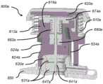
图14A是在击发之前和在移除使用前拉动插头PBUP 517a之前的插入机构600a的某些部件和特征(以状态一示出)的截面图。图14B是在移除PBUP 517a之后但在击发插入机构600a之前处于状态二的插入机构600a的截面图。图14C和图14D是在插入套管641a时的图14B的某些部件和特征(在从状态二到状态三的过渡期间示出)的截面图。这些视图示出了使用可移动背衬结构的套管载体612a与套管密封件630a的相互作用的细节。图14E是一旦插入套管641a但在缩回套管针647a之前的图14B的某些部件和特征(以状态三示出)的截面图。图14F是示出了在插入机构600a的击发、套管641a的插入和套管针647a的缩回之后的处于状态四的套管载体612a、套管密封件630a和套管针密封件680a的特写截面图。省略了插入机构600a的一些细节以简化图14A至图14F中的视图。例如,插入机构600a可以针对套管载体612a和套管针载体674a使用锁定机构(类似插入机构600所使用的锁定机构),但那些详细特征未在图14A至图14F中示出。类似地,插入机构600a可以使用套管触发按钮和触发连杆(类似插入机构600所使用的那些),并且套管针密封垫680a可以包括密封环(类似于套管针密封件680上的那些)。用于插入机构600a的部件的材料可以类似于上述用于插入机构600的那些的材料。14A is a cross-sectional view of certain components and features of
图14A和图14B示出了支撑在引导壳体620a上的套管载体612a、套管针647a、套管针载体674a、套管针密封件680a、套管针缩回弹簧682a、套管密封件630a、密封环631a和套管641a。图14A还示出了PBUP 517a,并且图14B还示出了主插入弹簧610a。在该实施方案中并且如图14B最佳所示,引导壳体狭槽624a包括一个或多个锥形624b,其接合套管针载体674a上的特征,从而致使套管针载体674a比套管载体612a旋转得更远,因此套管针载体674a从套管载体612a脱离,从而允许套管针缩回弹簧682a在套管插入之后将套管针缩回到插入机构600a中。Figures 14A and 14B
在该实施方案中,插入机构600a提供套管密封件630a,该套管密封件在击发之前没有被径向支撑,因为没有套管密封件保持器。相反,在该实施方案中,套管载体612a提供所有的径向压缩力。换句话说,先前实施方案使用固定背衬环(密封件保持器634),然而该实施方案使用了可移动背衬结构(套管载体612a的部分),该结构在从状态二到状态三的过渡期间接合套管密封件630a,并且保持接合在状态四。插入机构600a还提供了通过低套管插入力的高度有效的径向压缩密封和高度可靠的药物密封。即在插入操作之后,施加在密封件630a上的径向压缩力导致可靠的药物密封。In this embodiment, the
图14C至图14F示出了在使用可移动背衬结构(套管载体612a的部分)的该实施方案中的套管载体612a与套管密封件630a的相互作用的细节。图14C示出了插入机构600a开始从状态二过渡到状态三。当套管载体612a开始向下行进时,它首先接触套管密封件630a的上密封环631a,并开始捕获并围绕套管载体612a的表面之间的套管密封件630a。图14D示出了在套管载体612a已经使上密封环631a径向扩展并且开始接触下密封环631a之后的套管载体。上密封环和下密封环631a分开约2.5mm。图14E示出了处于状态三的插入机构600a,其中插入套管641a但在套管针647a缩回之前。在该状态下以及在状态四下,初始扩展的套管密封件630a与套管载体612a的可移动背衬结构接触,并且已经迫使上密封环631a与套管载体612a进行紧密接触。套管载体612a具有成角度的面向内的表面(即,不平行于或垂直于向下移动方向的表面,诸如截头圆锥形表面),并且套管密封件630a具有成角度的面向内的表面(即,不平行于或垂直于向下移动方向的表面,诸如截头圆锥形表面)。当套管载体612a向下移动时,施加到套管密封件630a的径向力增加,因为接触量以及因此径向力在以下之间增加:(i)套管载体612a的垂直表面和套管密封环631a以及(ii)套管载体612a的成角度表面和套管密封件630a。类似的概念适用于先前的实施方案,其中当套管载体612从状态二移动到状态四时,接触量以及因此径向力在以下之间增加:(i)套管载体612的垂直表面和套管密封环631以及(ii)套管密封件630与密封件保持器634和套管载体612两者。Figures 14C-14F show details of the interaction of the
同样与正上方的实施方案类似,当套管载体612继续向下移动时,在套管密封件630a的顶表面与载体内表面616a之间进行接触(参见图14A和图14B)。这种初始接触在套管载体612a仍向下移动时发生。因此,当套管载体612a继续向下移动时,载体内表面616a在套管密封件630a上施加增加的向下力,并且在其这样做时,套管密封件630a随着套管载体612a继续移动而被越来越多地压缩。如上所述,套管载体内表面616a和套管密封件630a的顶表面之间的该接触形成辅助面密封件。而且,当载体内表面616a从上方越来越多地推动在套管密封件630a上时,套管密封件630a越来越径向扩展,从而在以下之间产生附加径向压缩力:(i)密封环631a和套管载体612a以及(ii)套管密封件630a和套管载体612a的成角度表面。套管密封件630a最终可以径向扩展例如0.5mm。Also similar to the embodiment directly above, as the
这样,通过以下实现了高度有效和高度可靠的套管密封:(1)在套管载体内表面616a和套管密封件630a的顶表面处形成的面密封件,(2)密封环631a和套管载体612a之间的接触,(3)由套管载体612a施加的径向夹紧力,该套管载体用作可移动背衬环并提供套管密封件630a的径向压缩,以及(4)由套管载体612a在套管载体内表面616a处施加在套管密封件630a的顶部上的向下力,其使套管密封件630a径向扩展并且增加(a)由密封环631a抵靠套管载体612a施加的径向力以及(b)由套管密封件630a抵靠套管载体612a的成角度表面施加的径向力。这允许较低的插入力以用于在击发期间将套管载体612a、套管641a、套管针密封件680a和套管针647a插入套管密封件630a中,同时套管载体612a的夹紧动作在套管密封件630a上生成较大的径向力,从而维持高度可靠的液压密封以实现无泄漏操作。最小化的插入力可以进一步允许最小化主插入弹簧610a的尺寸。In this way, a highly effective and highly reliable casing seal is achieved by (1) the face seal formed at the casing carrier
现在将描述使以上插入机制在状态之间过渡所需的能量。该说明适用于插入机构600和插入机构600a。The energy required to transition the above insertion mechanism between states will now be described. This description applies to both
从状态一过渡到状态二所需的能量由用户物理移除PBUP 517/517a来供应。使插入机构600/600a从状态二过渡到状态三所需的能量由主插入弹簧610/610a供应。该能量主要由皮肤刺穿能量和密封件插入能量组成,并且其次由机构摩擦、套管密封件630/630a的压缩和套管针缩回的触发组成。用于从状态三过渡到状态四的能量由套管针缩回弹簧682/682a供应。讨论聚焦于当插入套管并完成药物路径的密封时从状态二到状态三的过渡。The energy required to transition from state one to state two is supplied by the user physically removing the
基于刺穿皮肤并将套管移动到正确插入深度所需的力对皮肤刺穿能量进行建模。如前所述,将套管641/641a的尖端(远侧端部)插入约6mm的深度。皮肤刺穿力从0N开始,在针尖处于皮下约2mm时上升到约5N的最大值,并且然后在针尖到达其最终6mm位置时下降到约3N。这将为皮肤刺穿产生约21N-mm的能量。The skin penetration energy is modeled based on the force required to penetrate the skin and move the cannula to the correct insertion depth. As before, the tip (distal end) of
密封件插入能量应当被最小化。在正上方的两个实施方案中,套管载体612/612a的密封表面具有约5mm的直径,并且需要间隔开约2.5mm的套管密封件。这意味着,当套管载体612/612a在套管641/641a达到状态三之前(在患者皮肤表面下方约6mm)仍需要行进约3.5mm时,上密封环631/631a接合套管载体612/612a,并且在套管641/641a到达状态三之前,下密封环631/631a与套管载体612/612a接合约1.0mm。Seal insertion energy should be minimized. In the two embodiments directly above, the sealing surface of the
有效的密封设计要求密封接触应力至少为被密封流体的压力。例如,如果最大药物流体压力为3巴(表压),并且密封环631/631a的接触宽度各自为约1mm(并且直径为约5mm,如上所述),则这导致上密封件和下密封件各自的密封径向力最小值为约4.8N。考虑到塑料上的弹性体的设计裕度/公差和为0.8的假定摩擦系数,这导致每个密封环631/631a的计算出的设计插入力为约5N。从能量角度来看,这表示用于状态二和状态三之间的过渡的针对上密封环631/631a的约17.5N-mm(3.5mm×5N)以及针对下密封环631/631a的约5N-mm(1mm×5N)。Effective seal design requires a seal contact stress of at least the pressure of the fluid being sealed. For example, if the maximum drug fluid pressure is 3 bar (gauge), and the contact width of the seal rings 631/631a is about 1 mm each (and about 5 mm in diameter, as described above), this results in upper and lower seals The respective seal radial force minimum is about 4.8N. Taking into account the design margin/tolerance of the elastomer on the plastic and an assumed coefficient of friction of 0.8, this results in a calculated design insertion force of about 5N for each
插入机构600/600a的机构是线性的,具有较低的摩擦损失。在前面给出的示例中,主插入弹簧提供77N-mm的总能量。给定约21N-mm的皮肤刺穿能量、约17.5N-mm的上密封环插入能量和约5N-mm的下密封环插入能量(总计约43.5N-mm),这留下了约33.5N-mm以用于摩擦、套管密封件630/630a的压缩,以及用于触发套管针缩回机构。该量的贮存能量可能不是必需的,因此较小的弹簧力可以是足够的。本文提出的插入机构是能量有效的,以及是高度可靠、紧凑、便宜且用户友好的。The mechanism of the
这里,在前面部分中描述的并且在各个附图中示出的示例性结构的上下文中呈现了各种方法和系统,仅出于解释的目的。尽管本方法和系统可以采用上述结构,但是它们不限于此。另外,本发明的实施方案可以合并上述方法或设备中的任意一种、少于全部的组合、或全部。Here, the various methods and systems are presented in the context of the example structures described in the preceding sections and shown in the various figures, for purposes of explanation only. Although the methods and systems may employ the structures described above, they are not limited thereto. In addition, embodiments of the present invention may incorporate any one, a combination of less than all, or all of the methods or apparatus described above.
尽管已经根据上面的优选实施方案描述了本文公开的发明,但对本领域技术人员来说,上述优选实施方案的多种修改和/或添加将是显而易见的。作为示例而非限制,本插入器和密封组件可以被合并到完全一次性输注泵中。意图将本发明的范围扩展到所有此类修改和/或添加,并且本发明的范围仅由下面阐述或以后添加的权利要求书限制。Although the invention disclosed herein has been described in terms of the above preferred embodiments, various modifications and/or additions to the above preferred embodiments will be apparent to those skilled in the art. By way of example and not limitation, the present inserter and seal assembly may be incorporated into a fully disposable infusion pump. It is intended that the scope of the present invention be extended to all such modifications and/or additions, and that the scope of the present invention be limited only by the claims set forth below or hereafter added.
最后,相对于本文可使用的术语,无论是在说明书中还是在权利要求书中,都应注意以下内容。术语“包括”、“包含”、“携带”、“具有”、“含有”、“涉及”等是开放式的,并且意指“包括但不限于”。诸如“第一”、“第二”、“第三”的序数术语本身并不表示一个元素相对于另一个元素或执行方法步骤的时间顺序的任何优先、优先级或顺序。相反,此类术语仅是用于区分具有某个名称的一个元素与具有相同名称的另一个元素(但对于序数术语而言)以区分元素的标签。“和/或”表示所列项目为替代方案,但替代方案也包括所列项目的任何组合。术语“大约”、“约”、“基本上”和“通常”允许与任何确切的尺寸、测量值和布置有特定量的变化,并且应当在本文公开的本发明的描述和操作的上下文内进行理解。诸如“顶”、“底”、“上”、“下”、“上方”和“下方”的术语是表示部件相对于彼此的空间关系,而不是相对于任何特定的空间或重力取向的空间关系。因此,这些术语旨在涵盖部件部分的组装,而不管该组件是按照附图所示和说明书中所描述的特定取向来定向、从该取向倒置、还是由此产生的任何其他旋转变化。Finally, with respect to terminology that may be used herein, whether in the specification or the claims, the following should be noted. The terms "comprising", "comprising", "carrying", "having", "containing", "involving" and the like are open ended and mean "including but not limited to". Ordinal terms such as "first," "second," and "third" do not, by themselves, denote any priority, priority, or order of one element over another or chronological order in which method steps are performed. Rather, such terms are merely labels used to distinguish one element with a certain name from another element with the same name (but for ordinal terms) to distinguish the elements. "And/or" indicates that the listed items are alternatives, but alternatives also include any combination of the listed items. The terms "about", "approximately", "substantially" and "generally" allow for a specific amount of variation from any exact size, measurement and arrangement and are to be made within the context of the description and operation of the invention disclosed herein understand. Terms such as "top", "bottom", "upper", "lower", "above" and "beneath" denote the spatial relationship of parts relative to each other and not to any particular spatial or gravitational orientation . Accordingly, these terms are intended to cover the assembly of component parts, regardless of whether the assembly is oriented in the particular orientation shown in the drawings and described in the specification, inverted from that orientation, or any other rotational variation resulting therefrom.
Claims (19)
Applications Claiming Priority (2)
| Application Number | Priority Date | Filing Date | Title |
|---|---|---|---|
| US201762528486P | 2017-07-04 | 2017-07-04 | |
| PCT/IB2018/055313WO2019008562A1 (en) | 2017-07-04 | 2018-07-18 | Ambulatory infusion pumps and assemblies for use with same |
Publications (2)
| Publication Number | Publication Date |
|---|---|
| CN112566680A CN112566680A (en) | 2021-03-26 |
| CN112566680Btrue CN112566680B (en) | 2023-02-28 |
Family
ID=63143311
Family Applications (1)
| Application Number | Title | Priority Date | Filing Date |
|---|---|---|---|
| CN201880045168.0AActiveCN112566680B (en) | 2017-07-04 | 2018-07-18 | Movable infusion pump and components for use therewith |
Country Status (6)
| Country | Link |
|---|---|
| US (2) | US11260171B2 (en) |
| EP (1) | EP3648816B1 (en) |
| CN (1) | CN112566680B (en) |
| CA (1) | CA3068788A1 (en) |
| DK (1) | DK3648816T3 (en) |
| WO (1) | WO2019008562A1 (en) |
Families Citing this family (26)
| Publication number | Priority date | Publication date | Assignee | Title |
|---|---|---|---|---|
| EP1762259B2 (en) | 2005-09-12 | 2025-01-01 | Unomedical A/S | Inserter for an infusion set with a first and second spring units |
| US8915879B2 (en) | 2010-09-24 | 2014-12-23 | Perqflo, Llc | Infusion pumps |
| US8905972B2 (en) | 2010-11-20 | 2014-12-09 | Perqflo, Llc | Infusion pumps |
| WO2012123274A1 (en) | 2011-03-14 | 2012-09-20 | Unomedical A/S | Inserter system with transport protection |
| US12178992B2 (en) | 2014-09-30 | 2024-12-31 | Medtronic Minimed, Inc. | Different disposable assemblies for the same reusable assembly |
| US10159786B2 (en) | 2014-09-30 | 2018-12-25 | Perqflo, Llc | Hybrid ambulatory infusion pumps |
| US10737016B2 (en) | 2015-02-18 | 2020-08-11 | Medtronic Minimed, Inc. | Ambulatory infusion pumps and reservoir assemblies for use with same |
| EP3413954B1 (en) | 2016-02-12 | 2025-09-03 | Medtronic MiniMed, Inc. | Ambulatory infusion pump and assemblies for use with same |
| CN119950880A (en) | 2017-05-05 | 2025-05-09 | 里珍纳龙药品有限公司 | Auto-injectors and related methods of use |
| US11260171B2 (en) | 2017-07-04 | 2022-03-01 | Medtronic Minimed, Inc. | Ambulatory infusion pumps and assemblies for use with same |
| EP3893965A4 (en)* | 2018-12-15 | 2022-08-31 | Biolark, Inc. | KINDLESS INFUSION SET FOR MEDICAL USE |
| JP7210290B2 (en)* | 2019-01-08 | 2023-01-23 | セイコーインスツル株式会社 | Feeding device and portable pouring device |
| WO2020219127A1 (en)* | 2019-04-23 | 2020-10-29 | Synolus Medical, Inc. | Wearable injector |
| US11458292B2 (en) | 2019-05-20 | 2022-10-04 | Unomedical A/S | Rotatable infusion device and methods thereof |
| EP3741405A1 (en)* | 2019-05-23 | 2020-11-25 | Ypsomed AG | Delivery device with sensorless motor control |
| EP3967338A1 (en) | 2020-09-09 | 2022-03-16 | Ypsomed AG | Patch injection device with an improved release liner removal |
| EP4243894A1 (en) | 2020-11-11 | 2023-09-20 | Medtronic MiniMed, Inc. | Remotely activated cannula insertion |
| US11951281B2 (en) | 2020-11-11 | 2024-04-09 | Medtronic Minimed, Inc. | Fluid conduit insertion devices |
| CN117836023A (en) | 2021-07-23 | 2024-04-05 | 康沃特克有限公司 | Port with piercing mechanism |
| EP4392093A4 (en)* | 2021-08-24 | 2025-05-21 | Zyno Medical, LLC | Field-chargeable transcutaneous drug delivery system |
| USD1007676S1 (en) | 2021-11-16 | 2023-12-12 | Regeneron Pharmaceuticals, Inc. | Wearable autoinjector |
| WO2024081580A1 (en)* | 2022-10-10 | 2024-04-18 | Tandem Diabetes Care, Inc. | Syringe pump drug delivery device |
| WO2024079643A1 (en)* | 2022-10-14 | 2024-04-18 | Nuova Ompi S.R.L. Unipersonale | Device for subcutaneous delivery of a medicament |
| US20250025627A1 (en)* | 2023-07-21 | 2025-01-23 | Medtronic Minimed, Inc. | Medicament infusion device |
| WO2025104040A1 (en) | 2023-11-14 | 2025-05-22 | Becton Dickinson France | Injection device including a sealing member, and method for removing said sealing member from the injection device |
| WO2025104037A1 (en) | 2023-11-14 | 2025-05-22 | Becton Dickinson France | Injection device including a sealing member, and method for removing said sealing member from the injection device |
Citations (1)
| Publication number | Priority date | Publication date | Assignee | Title |
|---|---|---|---|---|
| CN204972511U (en)* | 2014-07-02 | 2016-01-20 | 贝克顿·迪金森公司 | Micropump of medicine is carried through infusion |
Family Cites Families (89)
| Publication number | Priority date | Publication date | Assignee | Title |
|---|---|---|---|---|
| US1771219A (en) | 1926-10-04 | 1930-07-22 | George N Hein | Syringe |
| US3662753A (en) | 1970-05-25 | 1972-05-16 | Kitchener B Tassell | Syringe |
| US4379453A (en)* | 1978-12-28 | 1983-04-12 | Baron Howard C | Infusion system with self-generating pressure assembly |
| JPS59127595A (en) | 1983-01-05 | 1984-07-23 | Kokusai Electric Co Ltd | Pulse motor drive circuit |
| US4685903A (en) | 1984-01-06 | 1987-08-11 | Pacesetter Infusion, Ltd. | External infusion pump apparatus |
| CA1283827C (en) | 1986-12-18 | 1991-05-07 | Giorgio Cirelli | Appliance for injection of liquid formulations |
| US5176662A (en)* | 1990-08-23 | 1993-01-05 | Minimed Technologies, Ltd. | Subcutaneous injection set with improved cannula mounting arrangement |
| JPH04156857A (en) | 1990-10-19 | 1992-05-29 | Sharp Corp | Stepping motor control device for infusion pump |
| US5364510A (en) | 1993-02-12 | 1994-11-15 | Sematech, Inc. | Scheme for bath chemistry measurement and control for improved semiconductor wet processing |
| US5257980A (en) | 1993-04-05 | 1993-11-02 | Minimed Technologies, Ltd. | Subcutaneous injection set with crimp-free soft cannula |
| US5527299A (en)* | 1994-05-13 | 1996-06-18 | Critical Disposables, Inc. | One-piece rotator and manifold system |
| US5584813A (en) | 1995-06-07 | 1996-12-17 | Minimed Inc. | Subcutaneous injection set |
| US5549583A (en)* | 1995-08-04 | 1996-08-27 | Adam Spence Corporation | Surgical connector |
| US7329239B2 (en) | 1997-02-05 | 2008-02-12 | Medtronic Minimed, Inc. | Insertion device for an insertion set and method of using the same |
| US6093172A (en) | 1997-02-05 | 2000-07-25 | Minimed Inc. | Injector for a subcutaneous insertion set |
| US5851197A (en) | 1997-02-05 | 1998-12-22 | Minimed Inc. | Injector for a subcutaneous infusion set |
| US6607509B2 (en) | 1997-12-31 | 2003-08-19 | Medtronic Minimed, Inc. | Insertion device for an insertion set and method of using the same |
| US5785850A (en)* | 1997-03-17 | 1998-07-28 | Certified Technologies Corp. | Cleanable oil filter |
| US5779665A (en) | 1997-05-08 | 1998-07-14 | Minimed Inc. | Transdermal introducer assembly |
| US5968011A (en) | 1997-06-20 | 1999-10-19 | Maersk Medical A/S | Subcutaneous injection set |
| WO1999033504A1 (en) | 1997-12-31 | 1999-07-08 | Minimed Inc. | Insertion device for an insertion set and method of using the same |
| US6056718A (en) | 1998-03-04 | 2000-05-02 | Minimed Inc. | Medication infusion set |
| US5951521A (en) | 1998-09-25 | 1999-09-14 | Minimed Inc. | Subcutaneous implantable sensor set having the capability to remove deliver fluids to an insertion site |
| US6254586B1 (en) | 1998-09-25 | 2001-07-03 | Minimed Inc. | Method and kit for supplying a fluid to a subcutaneous placement site |
| US7766873B2 (en) | 1998-10-29 | 2010-08-03 | Medtronic Minimed, Inc. | Method and apparatus for detecting occlusions in an ambulatory infusion pump |
| US7621893B2 (en) | 1998-10-29 | 2009-11-24 | Medtronic Minimed, Inc. | Methods and apparatuses for detecting occlusions in an ambulatory infusion pump |
| US6461331B1 (en) | 1999-05-21 | 2002-10-08 | Minimed Inc. | Device and method for infusion of small molecule insulin mimetic materials |
| US6485465B2 (en) | 2000-03-29 | 2002-11-26 | Medtronic Minimed, Inc. | Methods, apparatuses, and uses for infusion pump fluid pressure and force detection |
| JP3546821B2 (en) | 2000-08-22 | 2004-07-28 | 村田機械株式会社 | Stepping motor drive circuit |
| EP1381408A4 (en) | 2001-02-22 | 2007-06-13 | Insulet Corp | Modular infusion device and method |
| EP1383560B2 (en)* | 2001-04-06 | 2023-04-26 | F. Hoffmann-La Roche AG | Infusion set |
| US7033338B2 (en) | 2002-02-28 | 2006-04-25 | Smiths Medical Md, Inc. | Cartridge and rod for axially loading medication pump |
| CA2741441C (en) | 2002-02-28 | 2013-11-26 | Clinton S. Vilks | Cartridge and pump with axial loading |
| US6902207B2 (en) | 2002-05-01 | 2005-06-07 | Medtronic Minimed, Inc. | Self sealing disconnect device |
| US6923791B2 (en) | 2003-03-31 | 2005-08-02 | Sterling Medivations, Inc. | Infusion device having offset flow path |
| EP1475113A1 (en) | 2003-05-08 | 2004-11-10 | Novo Nordisk A/S | External needle inserter |
| MXPA05013437A (en) | 2003-06-09 | 2007-08-24 | Nipro Diabetes Systems Inc | Coupling system for an infusion pump. |
| US7050940B2 (en) | 2004-03-17 | 2006-05-23 | International Business Machines Corporation | Method and system for maintaining and examining timers for network connections |
| US7303543B1 (en) | 2004-12-03 | 2007-12-04 | Medtronic Minimed, Inc. | Medication infusion set |
| EP1803934B1 (en) | 2005-12-28 | 2008-09-24 | Sensile Pat AG | Micropump |
| CN101432601A (en) | 2006-02-14 | 2009-05-13 | 巴特尔纪念研究院 | Accurate metering system |
| US20070191772A1 (en) | 2006-02-16 | 2007-08-16 | Animas Corporation | Straight insertion safety infusion set |
| JP2009539437A (en) | 2006-06-07 | 2009-11-19 | エフ.ホフマン−ラ ロシュ アーゲー | Rotary infusion set |
| CN102921062B (en)* | 2006-07-24 | 2015-04-01 | F·霍夫曼-拉罗氏股份公司 | Devices for fluid/drug delivery |
| US8435206B2 (en) | 2006-08-03 | 2013-05-07 | Smiths Medical Asd, Inc. | Interface for medical infusion pump |
| US7682338B2 (en)* | 2006-08-23 | 2010-03-23 | Medtronic Minimed, Inc. | Infusion medium delivery system, device and method with needle inserter and needle inserter device and method |
| DE102006045959B3 (en) | 2006-09-27 | 2008-01-10 | Lts Lohmann Therapie-Systeme Ag | Cylinder piston unit, e.g. for drug syringes with rubber pistons, has a cylinder and a piston guided in the cylinder and sealed with rubber in a sterile manner |
| US8696570B2 (en) | 2006-11-28 | 2014-04-15 | Roche Diagnostics Operations Inc. | Insertion device and method for inserting a subcutaneously insertable element into body |
| KR100749266B1 (en) | 2006-12-29 | 2007-08-13 | 박효남 | Chemical liquid injector |
| JP2008168297A (en) | 2007-01-05 | 2008-07-24 | Sumitomo Heavy Ind Ltd | Apparatus and method for laser beam machining |
| US8323250B2 (en) | 2007-04-30 | 2012-12-04 | Medtronic Minimed, Inc. | Adhesive patch systems and methods |
| JP5102350B2 (en)* | 2007-04-30 | 2012-12-19 | メドトロニック ミニメド インコーポレイテッド | Reservoir filling / bubble management / infusion medium delivery system and method using the system |
| US8002752B2 (en) | 2007-06-25 | 2011-08-23 | Medingo, Ltd. | Protector apparatus |
| JP2009030311A (en) | 2007-07-26 | 2009-02-12 | Naoyoshi Oishi | Hydraulic system for excavator, and lift pump for excavator |
| EP2022518A1 (en) | 2007-08-07 | 2009-02-11 | Sensile Pat AG | Modular drug delivery device for administering discrete doses of a medicament |
| DE102007049446A1 (en)* | 2007-10-16 | 2009-04-23 | Cequr Aps | Catheter introducer |
| ATE522240T1 (en)* | 2008-02-13 | 2011-09-15 | Unomedical As | SEAL BETWEEN A CANNULAR PART AND A FLUID PATH |
| DK3260145T3 (en) | 2008-04-09 | 2020-02-17 | Hoffmann La Roche | Fluid level sensor for a modular, skin adhesive medical fluid delivery system |
| CN101574550B (en) | 2008-05-06 | 2013-02-13 | 德昌电机(深圳)有限公司 | Injection device |
| US8128597B2 (en) | 2008-06-26 | 2012-03-06 | Calibra Medical, Inc. | Disposable infusion device with cannula port cover |
| JP5134142B2 (en) | 2008-09-22 | 2013-01-30 | フラウンホーファー−ゲゼルシャフト ツル フェルデルング デル アンゲヴァンテン フォルシュング エー ファウ | Apparatus and method for measuring at least one flow parameter |
| US7762524B2 (en)* | 2008-10-20 | 2010-07-27 | Baxter International Inc. | Barrier assembly for use with needleless connector |
| US8870848B2 (en) | 2008-10-31 | 2014-10-28 | Medtronic, Inc. | System and method for delivery of biologic agents |
| CN101745163B (en) | 2008-11-28 | 2013-12-04 | 德昌电机(深圳)有限公司 | Injection pump |
| DE102008062405A1 (en) | 2008-12-17 | 2010-11-18 | Lts Lohmann Therapie-Systeme Ag | Injector with cylinder-piston unit and permanently sterile active piston skirt |
| WO2010072005A1 (en) | 2008-12-24 | 2010-07-01 | Calasso, Irio, Giuseppe | System and methods for medicament infusion |
| EP2229970B1 (en) | 2009-03-16 | 2012-06-06 | F. Hoffmann-La Roche AG | Bubble trap system for an infusion pump device |
| EP2724739B1 (en) | 2009-07-30 | 2015-07-01 | Tandem Diabetes Care, Inc. | Portable infusion pump system |
| KR20120047896A (en)* | 2009-08-07 | 2012-05-14 | 우노메디컬 에이/에스 | Delivery device with sensor and one or more cannulas |
| US8858500B2 (en) | 2009-12-30 | 2014-10-14 | Medtronic Minimed, Inc. | Engagement and sensing systems and methods |
| US20120215163A1 (en) | 2009-12-30 | 2012-08-23 | Medtronic Minimed, Inc. | Sensing systems and methods |
| BR112012029642B1 (en) | 2010-05-20 | 2020-05-26 | Becton, Dickinson And Company | DRUG ADMINISTRATION DEVICE |
| US9498573B2 (en) | 2010-09-24 | 2016-11-22 | Perqflo, Llc | Infusion pumps |
| US9216249B2 (en) | 2010-09-24 | 2015-12-22 | Perqflo, Llc | Infusion pumps |
| US8915879B2 (en) | 2010-09-24 | 2014-12-23 | Perqflo, Llc | Infusion pumps |
| US9381300B2 (en) | 2010-09-24 | 2016-07-05 | Perqflo, Llc | Infusion pumps |
| US20130237781A1 (en)* | 2010-09-28 | 2013-09-12 | Steffen Gyrn | Transcutaneous Device |
| US8905972B2 (en) | 2010-11-20 | 2014-12-09 | Perqflo, Llc | Infusion pumps |
| CA2826094C (en) | 2011-02-09 | 2020-11-10 | Becton, Dickinson And Company | Subcutaneous infusion device |
| BR112015000541A2 (en) | 2012-07-11 | 2017-08-08 | Unitract Syringe Pty Ltd | insertion mechanism, drug delivery pump and method of operating an insertion mechanism |
| US9802030B2 (en) | 2013-01-25 | 2017-10-31 | Unl Holdings Llc | Integrated sliding seal fluid pathway connection and drug containers for drug delivery pumps |
| EP3050586A1 (en) | 2013-02-12 | 2016-08-03 | AbbVie Inc. | Syringe with two-stage sealing pressure |
| US20140296786A1 (en) | 2013-03-29 | 2014-10-02 | Animas Corporation | Fluid cartridge for medical infusion device |
| US10194842B2 (en) | 2014-09-03 | 2019-02-05 | Nova Biomedical Corporation | Subcutaneous sensor inserter and method |
| US10159786B2 (en) | 2014-09-30 | 2018-12-25 | Perqflo, Llc | Hybrid ambulatory infusion pumps |
| US10737016B2 (en) | 2015-02-18 | 2020-08-11 | Medtronic Minimed, Inc. | Ambulatory infusion pumps and reservoir assemblies for use with same |
| AU2016391055A1 (en) | 2016-02-02 | 2018-08-23 | Medtronic Minimed, Inc. | Hybrid ambulatory infusion pump with contactless power transmission |
| EP3413954B1 (en) | 2016-02-12 | 2025-09-03 | Medtronic MiniMed, Inc. | Ambulatory infusion pump and assemblies for use with same |
| US11260171B2 (en) | 2017-07-04 | 2022-03-01 | Medtronic Minimed, Inc. | Ambulatory infusion pumps and assemblies for use with same |
- 2018
- 2018-07-17USUS16/038,049patent/US11260171B2/enactiveActive
- 2018-07-18CNCN201880045168.0Apatent/CN112566680B/enactiveActive
- 2018-07-18WOPCT/IB2018/055313patent/WO2019008562A1/ennot_activeCeased
- 2018-07-18DKDK18752282.6Tpatent/DK3648816T3/enactive
- 2018-07-18EPEP18752282.6Apatent/EP3648816B1/enactiveActive
- 2018-07-18CACA3068788Apatent/CA3068788A1/enactivePending
- 2022
- 2022-01-20USUS17/580,090patent/US12390584B2/enactiveActive
Patent Citations (1)
| Publication number | Priority date | Publication date | Assignee | Title |
|---|---|---|---|---|
| CN204972511U (en)* | 2014-07-02 | 2016-01-20 | 贝克顿·迪金森公司 | Micropump of medicine is carried through infusion |
Also Published As
| Publication number | Publication date |
|---|---|
| WO2019008562A1 (en) | 2019-01-10 |
| US11260171B2 (en) | 2022-03-01 |
| EP3648816B1 (en) | 2024-04-10 |
| CA3068788A1 (en) | 2019-01-10 |
| CN112566680A (en) | 2021-03-26 |
| US20190015585A1 (en) | 2019-01-17 |
| US12390584B2 (en) | 2025-08-19 |
| EP3648816A1 (en) | 2020-05-13 |
| DK3648816T3 (en) | 2024-05-06 |
| US20220133993A1 (en) | 2022-05-05 |
Similar Documents
| Publication | Publication Date | Title |
|---|---|---|
| CN112566680B (en) | Movable infusion pump and components for use therewith | |
| US12397109B2 (en) | Ambulatory infusion pumps and assemblies for use with same | |
| US11684712B2 (en) | Ambulatory infusion pumps and reservoir assemblies for use with same | |
| US12070576B2 (en) | Hybrid ambulatory infusion pumps | |
| US8414532B2 (en) | Modular drug delivery device for administering discrete doses of a medicament | |
| US20110021993A1 (en) | Miniature disposable or partially reusable dosing pump | |
| EP3411097B1 (en) | Hybrid ambulatory infusion pump with contactless power transmission | |
| CN116457041A (en) | Remotely activated cannula insertion | |
| CN115364304A (en) | Different disposable assemblies for the same reusable assembly | |
| WO2023180327A1 (en) | An improved conveying device for cold injection |
Legal Events
| Date | Code | Title | Description |
|---|---|---|---|
| PB01 | Publication | ||
| PB01 | Publication | ||
| SE01 | Entry into force of request for substantive examination | ||
| SE01 | Entry into force of request for substantive examination | ||
| GR01 | Patent grant | ||
| GR01 | Patent grant |