CN112547143B - Micro-fluidic chip and blood cell detection device - Google Patents
Micro-fluidic chip and blood cell detection deviceDownload PDFInfo
- Publication number
- CN112547143B CN112547143BCN201910917654.3ACN201910917654ACN112547143BCN 112547143 BCN112547143 BCN 112547143BCN 201910917654 ACN201910917654 ACN 201910917654ACN 112547143 BCN112547143 BCN 112547143B
- Authority
- CN
- China
- Prior art keywords
- micro
- sample
- channel
- branch
- microelectrode
- Prior art date
- Legal status (The legal status is an assumption and is not a legal conclusion. Google has not performed a legal analysis and makes no representation as to the accuracy of the status listed.)
- Active
Links
Images


Classifications
- B—PERFORMING OPERATIONS; TRANSPORTING
- B01—PHYSICAL OR CHEMICAL PROCESSES OR APPARATUS IN GENERAL
- B01L—CHEMICAL OR PHYSICAL LABORATORY APPARATUS FOR GENERAL USE
- B01L3/00—Containers or dishes for laboratory use, e.g. laboratory glassware; Droppers
- B01L3/50—Containers for the purpose of retaining a material to be analysed, e.g. test tubes
- B01L3/502—Containers for the purpose of retaining a material to be analysed, e.g. test tubes with fluid transport, e.g. in multi-compartment structures
- B01L3/5027—Containers for the purpose of retaining a material to be analysed, e.g. test tubes with fluid transport, e.g. in multi-compartment structures by integrated microfluidic structures, i.e. dimensions of channels and chambers are such that surface tension forces are important, e.g. lab-on-a-chip
- B01L3/502761—Containers for the purpose of retaining a material to be analysed, e.g. test tubes with fluid transport, e.g. in multi-compartment structures by integrated microfluidic structures, i.e. dimensions of channels and chambers are such that surface tension forces are important, e.g. lab-on-a-chip specially adapted for handling suspended solids or molecules independently from the bulk fluid flow, e.g. for trapping or sorting beads, for physically stretching molecules
- G—PHYSICS
- G01—MEASURING; TESTING
- G01N—INVESTIGATING OR ANALYSING MATERIALS BY DETERMINING THEIR CHEMICAL OR PHYSICAL PROPERTIES
- G01N33/00—Investigating or analysing materials by specific methods not covered by groups G01N1/00 - G01N31/00
- G01N33/48—Biological material, e.g. blood, urine; Haemocytometers
- G01N33/50—Chemical analysis of biological material, e.g. blood, urine; Testing involving biospecific ligand binding methods; Immunological testing
- G01N33/5002—Partitioning blood components
- G—PHYSICS
- G01—MEASURING; TESTING
- G01N—INVESTIGATING OR ANALYSING MATERIALS BY DETERMINING THEIR CHEMICAL OR PHYSICAL PROPERTIES
- G01N33/00—Investigating or analysing materials by specific methods not covered by groups G01N1/00 - G01N31/00
- G01N33/48—Biological material, e.g. blood, urine; Haemocytometers
- G01N33/50—Chemical analysis of biological material, e.g. blood, urine; Testing involving biospecific ligand binding methods; Immunological testing
- G01N33/53—Immunoassay; Biospecific binding assay; Materials therefor
- G01N33/536—Immunoassay; Biospecific binding assay; Materials therefor with immune complex formed in liquid phase
- G01N33/537—Immunoassay; Biospecific binding assay; Materials therefor with immune complex formed in liquid phase with separation of immune complex from unbound antigen or antibody
- B—PERFORMING OPERATIONS; TRANSPORTING
- B01—PHYSICAL OR CHEMICAL PROCESSES OR APPARATUS IN GENERAL
- B01L—CHEMICAL OR PHYSICAL LABORATORY APPARATUS FOR GENERAL USE
- B01L2200/00—Solutions for specific problems relating to chemical or physical laboratory apparatus
- B01L2200/06—Fluid handling related problems
- B01L2200/061—Counting droplets
- B—PERFORMING OPERATIONS; TRANSPORTING
- B01—PHYSICAL OR CHEMICAL PROCESSES OR APPARATUS IN GENERAL
- B01L—CHEMICAL OR PHYSICAL LABORATORY APPARATUS FOR GENERAL USE
- B01L2200/00—Solutions for specific problems relating to chemical or physical laboratory apparatus
- B01L2200/06—Fluid handling related problems
- B01L2200/0636—Focussing flows, e.g. to laminate flows
- B—PERFORMING OPERATIONS; TRANSPORTING
- B01—PHYSICAL OR CHEMICAL PROCESSES OR APPARATUS IN GENERAL
- B01L—CHEMICAL OR PHYSICAL LABORATORY APPARATUS FOR GENERAL USE
- B01L2200/00—Solutions for specific problems relating to chemical or physical laboratory apparatus
- B01L2200/06—Fluid handling related problems
- B01L2200/0647—Handling flowable solids, e.g. microscopic beads, cells, particles
- B01L2200/0652—Sorting or classification of particles or molecules
- B—PERFORMING OPERATIONS; TRANSPORTING
- B01—PHYSICAL OR CHEMICAL PROCESSES OR APPARATUS IN GENERAL
- B01L—CHEMICAL OR PHYSICAL LABORATORY APPARATUS FOR GENERAL USE
- B01L2200/00—Solutions for specific problems relating to chemical or physical laboratory apparatus
- B01L2200/10—Integrating sample preparation and analysis in single entity, e.g. lab-on-a-chip concept
- B—PERFORMING OPERATIONS; TRANSPORTING
- B01—PHYSICAL OR CHEMICAL PROCESSES OR APPARATUS IN GENERAL
- B01L—CHEMICAL OR PHYSICAL LABORATORY APPARATUS FOR GENERAL USE
- B01L2300/00—Additional constructional details
- B01L2300/06—Auxiliary integrated devices, integrated components
- B01L2300/0627—Sensor or part of a sensor is integrated
- B01L2300/0645—Electrodes
- B—PERFORMING OPERATIONS; TRANSPORTING
- B01—PHYSICAL OR CHEMICAL PROCESSES OR APPARATUS IN GENERAL
- B01L—CHEMICAL OR PHYSICAL LABORATORY APPARATUS FOR GENERAL USE
- B01L2300/00—Additional constructional details
- B01L2300/08—Geometry, shape and general structure
- B01L2300/0861—Configuration of multiple channels and/or chambers in a single devices
- B01L2300/0864—Configuration of multiple channels and/or chambers in a single devices comprising only one inlet and multiple receiving wells, e.g. for separation, splitting
- B—PERFORMING OPERATIONS; TRANSPORTING
- B01—PHYSICAL OR CHEMICAL PROCESSES OR APPARATUS IN GENERAL
- B01L—CHEMICAL OR PHYSICAL LABORATORY APPARATUS FOR GENERAL USE
- B01L2400/00—Moving or stopping fluids
- B01L2400/04—Moving fluids with specific forces or mechanical means
- B01L2400/0403—Moving fluids with specific forces or mechanical means specific forces
- B01L2400/0415—Moving fluids with specific forces or mechanical means specific forces electrical forces, e.g. electrokinetic
Landscapes
- Health & Medical Sciences (AREA)
- Chemical & Material Sciences (AREA)
- Life Sciences & Earth Sciences (AREA)
- Immunology (AREA)
- Engineering & Computer Science (AREA)
- Hematology (AREA)
- Biomedical Technology (AREA)
- General Health & Medical Sciences (AREA)
- Analytical Chemistry (AREA)
- Molecular Biology (AREA)
- Urology & Nephrology (AREA)
- Physics & Mathematics (AREA)
- Food Science & Technology (AREA)
- Medicinal Chemistry (AREA)
- Microbiology (AREA)
- Cell Biology (AREA)
- Biochemistry (AREA)
- Biotechnology (AREA)
- General Physics & Mathematics (AREA)
- Pathology (AREA)
- Dispersion Chemistry (AREA)
- Clinical Laboratory Science (AREA)
- Chemical Kinetics & Catalysis (AREA)
- Fluid Mechanics (AREA)
- Automatic Analysis And Handling Materials Therefor (AREA)
Abstract
Translated fromChinese
Description
Translated fromChinese技术领域technical field
本发明涉及体外诊断(IVD)中的即时诊断(POCT)领域,具体涉及一种微流控芯片及血细胞检测装置。The invention relates to the field of point-of-care diagnosis (POCT) in in vitro diagnosis (IVD), in particular to a microfluidic chip and a blood cell detection device.
背景技术Background technique
微流控芯片是一种以在微米尺度空间对流体进行操控为主要特征的科学技术,具有将生物、化学等实验室的基本功能微缩到一个几平方厘米芯片上的能力,因此又称芯片实验室。微流控芯片多由微通道形成网络,以可控流体贯穿整个系统,用以实现常规化学或生物等实验室的各种功能。微流控芯片的基本特征和最大优势是多种单元技术在微小可控平台上灵活组合和规模集成。Microfluidic chip is a science and technology characterized by the manipulation of fluids in micron-scale space. It has the ability to miniaturize the basic functions of biology, chemistry and other laboratories on a chip of several square centimeters, so it is also called chip experiment. room. Microfluidic chips are mostly composed of microchannels to form a network to run through the entire system with controllable fluids to achieve various functions in laboratories such as conventional chemistry or biology. The basic feature and greatest advantage of microfluidic chips is the flexible combination and scale integration of multiple unit technologies on tiny controllable platforms.
生物粒子计数功能在医疗诊断领域有着广泛的应用。例如医院常用的血常规化验就是利用生物粒子计数的方法,对血液中的红细胞、血红蛋白、白细胞、血小板等粒子进行分类统计,在医学上具有很强的诊断参考价值。目前市面上常见的粒子计数产品采用流式细胞术的方法,使样本形成单细胞流,然后再利用电阻抗、光散射、电导、细胞化学染色等不同方法对粒子进行检测与统计。此类产品对检测仪器的要求很高,导致其造价高昂,不适用于基层医疗场景。Biological particle counting function has a wide range of applications in the field of medical diagnosis. For example, routine blood tests commonly used in hospitals use the method of biological particle counting to classify and count red blood cells, hemoglobin, white blood cells, platelets and other particles in the blood, which has a strong diagnostic reference value in medicine. At present, the common particle counting products on the market use the method of flow cytometry to make the sample form a single-cell flow, and then use different methods such as electrical impedance, light scattering, conductance, and cytochemical staining to detect and count the particles. Such products have high requirements on testing instruments, resulting in high cost and are not suitable for primary medical scenarios.
免疫检测在医疗诊断领域的应用则更为普遍,大量与人体相关的疾病都可以利用免疫检测技术来进行诊断。例如,与感染相关的生物标志物以及与心脏相关的生物标志物等,均可利用免疫检测技术进行诊断。免疫检测技术以一种或多种抗体作为分析试剂,对待测物进行定量或定性分析。The application of immune detection in the field of medical diagnosis is more common, and a large number of diseases related to the human body can be diagnosed by using immune detection technology. For example, biomarkers related to infection and biomarkers related to heart can be diagnosed using immunodetection technology. Immunodetection technology uses one or more antibodies as analytical reagents to perform quantitative or qualitative analysis of the analyte.
目前市面上已经出现了一些利用微流控芯片来进行免疫检测的产品,例如微点生物的mLabs、万孚生物的飞测等。这些产品大都采用免疫荧光的方式来对免疫反应进行检测,由于涉及到了荧光的激发与接收,使得仪器成本偏高,不利于在基层医疗和家庭医疗的场景中推广。At present, some products using microfluidic chips for immune detection have appeared on the market, such as the mLabs of Microdot Bio and the flight test of Wanfu Bio. Most of these products use immunofluorescence to detect immune responses. Due to the excitation and reception of fluorescence, the cost of the instrument is high, which is not conducive to promotion in primary medical and family medical scenarios.
由此可见,目前市面上的生物粒子计数产品与免疫检测产品均存在设备仪器复杂且体积庞大,造价高昂等缺点,不利于在基层医疗和家庭医疗的推广和普及。It can be seen that the biological particle counting products and immune detection products currently on the market have the disadvantages of complex equipment, bulky, and high cost, which are not conducive to the promotion and popularization of primary medical care and family medical care.
发明内容SUMMARY OF THE INVENTION
本发明的目的在于提供一种微流控芯片及血细胞检测装置,能够解决现有技术中血细胞分析仪器设备成本高、操作要求高的问题。The purpose of the present invention is to provide a microfluidic chip and a blood cell detection device, which can solve the problems of high cost of blood cell analysis instruments and high operation requirements in the prior art.
本发明所提供的技术方案如下:The technical scheme provided by the present invention is as follows:
本发明至少一实施例中提供一种微流控芯片,包括:At least one embodiment of the present invention provides a microfluidic chip, comprising:
样本入口;sample entry;
样本废液收集口;Sample waste liquid collection port;
及连通于所述样本入口与所述样本废液收集口之间的样本微流道;and a sample microfluidic channel connected between the sample inlet and the sample waste liquid collection port;
其中,在所述样本微流道内设置有至少一对微电极,所述至少一对微电极能够在待测样本通过所述样本微流道时,产生信号变化以检测所述待测样本。Wherein, at least a pair of micro-electrodes are arranged in the sample micro-channel, and the at least one pair of micro-electrodes can generate signal changes to detect the sample to be tested when the sample to be tested passes through the sample micro-channel.
示例性的,所述样本微流道包括用于检测待测样本内预定生物粒子数量的粒子计数区,所述粒子计数区包括从所述样本入口分支出来、相互独立的多个分支微流道,每一所述分支微流道内设置至少一组微电极单元,每组所述微电极单元包括间隔设置的两个微电极,每组所述微电极单元中的两个微电极均垂直于所述分支微流道设置。Exemplarily, the sample microfluidic channel includes a particle counting area for detecting the predetermined number of biological particles in the sample to be tested, and the particle counting area includes a plurality of branched microfluidic channels that are branched from the sample inlet and are independent of each other. , at least one group of micro-electrode units is arranged in each of the branch micro-channels, each group of the micro-electrode units includes two micro-electrodes arranged at intervals, and the two micro-electrodes in each group of the micro-electrode units are perpendicular to the The branched microchannel setup described above.
示例性的,所述分支微流道的宽度d1大于1个所述预定生物粒子的直径D,并小于2个所述预定生物粒子的直径D;且所述分支微流道的深度h1大于1个所述预定生物粒子的直径D,并小于2个所述预定生物粒子的直径D。Exemplarily, the width d1 of the branch micro-channel is greater than the diameter D of one predetermined biological particle, and is less than the diameter D of two predetermined biological particles; and the depth h1 of the branch micro-channel It is larger than the diameter D of one of the predetermined biological particles, and smaller than the diameter D of two of the predetermined biological particles.
示例性的,所述分支微流道的数量为5~20个,且所述分支微流道的宽度d1为20~50μm,深度h1为20~50μm,流道总长度L为5~20mm。Exemplarily, the number of the branch micro-channels is 5-20, the width d1 of the branch micro-channel is 20-50 μm, the depth h1 is 20-50 μm, and the total length L of the channel is 5-50 μm. 20mm.
示例性的,所述粒子计数区中的各分支微流道从所述样本入口侧向所述样本废液收集口侧依次包括:分支段、平行段及汇合段,Exemplarily, each branch microfluidic channel in the particle counting area sequentially includes a branch section, a parallel section and a confluence section from the sample inlet side to the sample waste liquid collection port side,
在所述分支段,多个分支微流道从所述样本入口一侧向所述样本废液收集口一侧呈逐渐分散状分支开;In the branch section, a plurality of branch microfluidic channels branch from the sample inlet side to the sample waste liquid collection port side in a gradually dispersed shape;
在所述平行段,多个分支微流道相互平行;In the parallel section, a plurality of branch micro-channels are parallel to each other;
在所述汇合段,多个分支微流道从所述样本入口一侧向所述样本废液收集口一侧呈逐渐收敛状汇合;In the converging section, a plurality of branch microfluidic channels converge in a gradually converging shape from the sample inlet side to the sample waste liquid collection port side;
其中,所述微电极单元设置在各所述分支微流道的所述平行段。Wherein, the micro-electrode units are arranged in the parallel sections of each of the branch micro-channels.
示例性的,每一所述分支微流道内设置有至少2个所述微电极单元。Exemplarily, at least two of the micro-electrode units are disposed in each of the branch micro-channels.
示例性的,每组所述微电极单元中,每个微电极的宽度d2与所述预定生物粒子的直径D的差值为0~5μm,且两个微电极之间的间距d3与所述预定生物粒子的直径D之间的差值为0~10μm。Exemplarily, in each group of the microelectrode units, the difference between the widthd2 of each microelectrode and the diameter D of the predetermined biological particle is 0-5 μm, and the distanced3 between the two microelectrodes is equal to The difference between the diameters D of the predetermined biological particles is 0˜10 μm.
示例性的,每一组所述微电极单元中,每个微电极的宽度d2为10~30μm,高度h2为0.02~0.2μm,且两个微电极之间的间距为20-50μm。Exemplarily, in each group of the micro-electrode units, the width d2 of each micro-electrode is 10-30 μm, the height h2 is 0.02-0.2 μm, and the distance between the two micro-electrodes is 20-50 μm.
示例性的,所述样本微流道包括用于检测待测样本内预定抗体或抗原浓度的免疫检测区,所述免疫检测区包括汇合微流道,所述汇合微流道内设置有微电极阵列,所述微电极阵列的表面修饰有用于捕获所述预定抗体或抗原的辅助物,以使待测样本通过所述汇合微流道时,所述待测样本内的所述预定抗体或抗原被所述辅助物捕获,所述微电极阵列产生信号变化。Exemplarily, the sample microfluidic channel includes an immunodetection area for detecting the concentration of a predetermined antibody or antigen in the sample to be tested, the immunodetection area includes a confluent microfluidic channel, and a microelectrode array is arranged in the confluent microfluidic channel. , the surface of the microelectrode array is modified with an auxiliary for capturing the predetermined antibody or antigen, so that when the sample to be tested passes through the confluent microfluidic channel, the predetermined antibody or antigen in the sample to be tested is The aid captures and the microelectrode array produces a signal change.
示例性的,所述粒子计数区的各所述分支微流道的出口端汇合于所述汇合微流道,且所述汇合微流道连通于所述粒子计数区的多个所述分支微流道与所述样本废液收集口之间。Exemplarily, the outlet ends of each of the branched microchannels in the particle counting area are merged with the merged microchannel, and the merged microchannel is connected to a plurality of the branched microchannels in the particle counting area. between the flow channel and the sample waste liquid collection port.
示例性的,所述微电极阵列为插指状结构。Exemplarily, the microelectrode array is an interdigitated structure.
示例性的,所述微电极阵列中的每个微电极的宽度d4为3-5μm,高度h2为0.02~0.2μm,数量为10~900之间;Exemplarily, the widthd4 of each microelectrode in the microelectrode array is 3-5 μm, the height h2 is0.02-0.2 μm, and the number is between 10-900;
所述汇合微流道为一个单独的微流道,宽度为0.1~2mm,深度为0.04~0.1mm,流道总长度为5~10mm。The confluent micro-channel is a single micro-channel, the width is 0.1-2 mm, the depth is 0.04-0.1 mm, and the total length of the channel is 5-10 mm.
本发明实施例至少还提供了一种血细胞检测装置,包括:Embodiments of the present invention further provide at least a blood cell detection device, including:
如上所述的微流控芯片;The microfluidic chip as described above;
样本流速控制机构,用于使得待测样本以预定流速通过所述微流控芯片上的所述样本微流道;a sample flow rate control mechanism, configured to make the sample to be tested pass through the sample microfluidic channel on the microfluidic chip at a predetermined flow rate;
及检测机构,电连接至所述微流控芯片上的所述微电极,用于检测所述微流控芯片的所述微电极的信号变化以检测所述待测样本。and a detection mechanism, which is electrically connected to the micro-electrodes on the micro-fluidic chip, and is used for detecting signal changes of the micro-electrodes of the micro-fluidic chip to detect the sample to be tested.
示例性的,所述样本流速控制机构包括:用于向所述样本入口内的待测样本提供气压或者液压驱动力的气压或液压驱动单元。Exemplarily, the sample flow rate control mechanism includes: a pneumatic or hydraulic driving unit for providing a pneumatic or hydraulic driving force to the sample to be tested in the sample inlet.
示例性的,所述检测机构包括第一电源、第一电阻及第一检测器;所述第一电源的一端电连接至每组所述微电极单元中的一个微电极,所述第一电源的另一端通过所述电阻电连接至每组所述微电极单元中的另一微电极上,所述第一检测器与每组所述微电极单元中的两个微电极相连;Exemplarily, the detection mechanism includes a first power supply, a first resistor and a first detector; one end of the first power supply is electrically connected to one microelectrode in each group of the microelectrode units, and the first power supply The other end of the microelectrode is electrically connected to another microelectrode in each group of the microelectrode units through the resistance, and the first detector is connected to the two microelectrodes in each group of the microelectrode units;
其中,当每一所述分支微流道内设置有至少2个所述微电极单元时,所述第一检测器包括:Wherein, when at least two of the micro-electrode units are arranged in each of the branch micro-channels, the first detector includes:
第一接收器,用于接收每一所述微电极单元的信号;a first receiver for receiving signals from each of the micro-electrode units;
第一比较器,用于比较同一所述分支微流道内的各所述微电极单元的信号;a first comparator for comparing the signals of each of the micro-electrode units in the same branch micro-channel;
第一判断器,用于当同一所述分支微流道内的各所述微电极单元的信号差值在阈值内时,判断检测结果准确;当同一所述分支微流道内的各所述微电极单元的信号差值在阈值外时,判断检测结果不准确;a first determiner, configured to determine that the detection result is accurate when the signal difference of each of the micro-electrode units in the same branch micro-channel is within a threshold; when each of the micro-electrodes in the same branch micro-channel When the signal difference of the unit is outside the threshold, it is judged that the detection result is inaccurate;
第一计算器,用于当所述第一判断器判断为检测结果准确时,根据所述第一接收器所接收的信号变化,计算所述预定生物粒子的数量a first calculator, configured to calculate the number of the predetermined biological particles according to the change of the signal received by the first receiver when the first determiner determines that the detection result is accurate
示例性的,所述检测机构包括第二电源、第二电阻以及第二检测器;所述第二电源的一端电连接至所述微电极阵列中的一个微电极,所述第二电源的另一端通过所述电阻电连接至所述微电极阵列中的另一微电极上,所述第二检测器与所述微电极阵列中的两个微电极相连;其中,Exemplarily, the detection mechanism includes a second power source, a second resistor and a second detector; one end of the second power source is electrically connected to one microelectrode in the microelectrode array, and the other end of the second power source is electrically connected to one microelectrode in the microelectrode array. One end is electrically connected to another microelectrode in the microelectrode array through the resistor, and the second detector is connected to two microelectrodes in the microelectrode array; wherein,
所述第二检测器包括:The second detector includes:
第二接收器,用于接收所述微电极阵列的信号;a second receiver for receiving signals from the micro-electrode array;
第二计算器,用于根据所述第二接收器所接收的信号变化,计算所述预定抗体或抗原的浓度。The second calculator is used for calculating the concentration of the predetermined antibody or antigen according to the change of the signal received by the second receiver.
本发明所带来的有益效果如下:The beneficial effects brought by the present invention are as follows:
本发明实施例提供的微流控芯片及血细胞检测装置,基于电化学阻抗检测法,根据待测样本通过微流道时,检测微流控芯片的微电极之间的信号变化,就可以测定待测样本,例如,生物粒子数量及抗体抗原的浓度等,从而实现血细胞的准确计数及免疫检测,由于本发明装置结构简单、操作方便、灵敏可靠,从而能够大大降低测量成本、免维护、提高测量效率、且适合医院床边诊断、社区诊所和个人家庭等使用。The microfluidic chip and the blood cell detection device provided by the embodiments of the present invention are based on the electrochemical impedance detection method. When the sample to be tested passes through the microchannel, the signal change between the microelectrodes of the microfluidic chip can be detected. For example, the number of biological particles and the concentration of antibody and antigen, etc., so as to realize the accurate counting and immune detection of blood cells. Because the device of the present invention is simple in structure, convenient in operation, sensitive and reliable, it can greatly reduce the measurement cost, be maintenance-free, and improve the measurement Efficient and suitable for use in hospital bedside diagnosis, community clinics and individual households.
此外,一种示例性的实施例中所提供的微流控芯片及血细胞检测装置,将生物粒子计数与免疫检测功能结合在同一芯片上,仪器集成化程度高,且采用电化学阻抗检测原理,可以简化设备,设备成本降低,且更加便携化;同时,可以一次进样进行两种分析(粒子数量分析和免疫检测分析),减少采样量,加快检测速度。In addition, the microfluidic chip and blood cell detection device provided in an exemplary embodiment combine biological particle counting and immune detection functions on the same chip, the instrument has a high degree of integration, and adopts the electrochemical impedance detection principle, The equipment can be simplified, the equipment cost is reduced, and the equipment is more portable; at the same time, two kinds of analysis (particle number analysis and immunodetection analysis) can be performed in one injection, reducing the sampling amount and speeding up the detection speed.
附图说明Description of drawings
图1表示本发明所提供的微流控芯片的一种示例性实施例的结构示意图;FIG. 1 shows a schematic structural diagram of an exemplary embodiment of a microfluidic chip provided by the present invention;
图2表示本发明所提供的微流控芯片的另一种示例性实施例的结构示意图;FIG. 2 shows a schematic structural diagram of another exemplary embodiment of the microfluidic chip provided by the present invention;
图3表示图2中A-A向的截面结构示意图;Figure 3 shows a schematic view of the cross-sectional structure in the direction A-A in Figure 2;
图4表示本发明所提供的微流控芯片的另一种示例性实施例的结构示意图;FIG. 4 is a schematic structural diagram of another exemplary embodiment of the microfluidic chip provided by the present invention;
图5图4中B-B向的截面结构示意图;Figure 5 is a schematic diagram of a cross-sectional structure in the direction B-B in Figure 4;
图6表示本发明所提供的微流控芯片的另一种示例性实施例的结构示意图;FIG. 6 is a schematic structural diagram of another exemplary embodiment of the microfluidic chip provided by the present invention;
图7表示本发明所提供的微流控芯片的另一种示例性实施例的结构示意图。FIG. 7 is a schematic structural diagram of another exemplary embodiment of the microfluidic chip provided by the present invention.
具体实施方式Detailed ways
为使本公开实施例的目的、技术方案和优点更加清楚,下面将结合本公开实施例的附图,对本公开实施例的技术方案进行清楚、完整地描述。显然,所描述的实施例是本公开的一部分实施例,而不是全部的实施例。基于所描述的本公开的实施例,本领域普通技术人员在无需创造性劳动的前提下所获得的所有其他实施例,都属于本公开保护的范围。In order to make the purpose, technical solutions and advantages of the embodiments of the present disclosure more clear, the technical solutions of the embodiments of the present disclosure will be clearly and completely described below with reference to the accompanying drawings of the embodiments of the present disclosure. Obviously, the described embodiments are some, but not all, embodiments of the present disclosure. Based on the described embodiments of the present disclosure, all other embodiments obtained by those of ordinary skill in the art without creative efforts fall within the protection scope of the present disclosure.
除非另外定义,本公开使用的技术术语或者科学术语应当为本公开所属领域内具有一般技能的人士所理解的通常意义。本公开中使用的“第一”、“第二”以及类似的词语并不表示任何顺序、数量或者重要性,而只是用来区分不同的组成部分。同样,“一个”、“一”或者“该”等类似词语也不表示数量限制,而是表示存在至少一个。“包括”或者“包含”等类似的词语意指出现该词前面的元件或者物件涵盖出现在该词后面列举的元件或者物件及其等同,而不排除其他元件或者物件。“连接”或者“相连”等类似的词语并非限定于物理的或者机械的连接,而是可以包括电性的连接,不管是直接的还是间接的。“上”、“下”、“左”、“右”等仅用于表示相对位置关系,当被描述对象的绝对位置改变后,则该相对位置关系也可能相应地改变。Unless otherwise defined, technical or scientific terms used in this disclosure shall have the ordinary meaning as understood by one of ordinary skill in the art to which this disclosure belongs. As used in this disclosure, "first," "second," and similar terms do not denote any order, quantity, or importance, but are merely used to distinguish the various components. Likewise, words such as "a," "an," or "the" do not denote a limitation of quantity, but rather denote the presence of at least one. "Comprises" or "comprising" and similar words mean that the elements or things appearing before the word encompass the elements or things recited after the word and their equivalents, but do not exclude other elements or things. Words like "connected" or "connected" are not limited to physical or mechanical connections, but may include electrical connections, whether direct or indirect. "Up", "Down", "Left", "Right", etc. are only used to represent the relative positional relationship, and when the absolute position of the described object changes, the relative positional relationship may also change accordingly.
针对现有技术中血细胞检测装置均存在设备仪器复杂且体积庞大,造价高昂等缺点,不利于在基层医疗和家庭医疗的推广和普及的问题,本发明实施例提供了一种微流控芯片及血细胞检测装置,能够解决现有技术中血细胞分析仪器设备成本高、操作要求高的问题,结构简单,操作方便,可大大降低成本,适合医院床边诊断、社区诊所和个人家庭等使用。Aiming at the problems that the blood cell detection devices in the prior art have the disadvantages of complex equipment, large volume, and high cost, which are not conducive to the promotion and popularization in primary medical care and family medical care, the embodiment of the present invention provides a microfluidic chip and a microfluidic control chip. The blood cell detection device can solve the problems of high cost and high operation requirements of blood cell analysis instruments in the prior art.
如图1、图2、图4和图6所示,本发明至少一实施例中提供一种微流控芯片,包括:As shown in FIG. 1 , FIG. 2 , FIG. 4 and FIG. 6 , at least one embodiment of the present invention provides a microfluidic chip, including:
样本入口100;
样本废液收集口200;Sample waste
及连通于所述样本入口100与所述样本废液收集口200之间的样本微流道300;and a
其中,在所述样本微流道300内设置有至少一对微电极,所述至少一对微电极能够在待测样本通过所述样本微流道300时,产生信号变化以检测所述待测样本。Wherein, at least one pair of micro-electrodes is disposed in the
本发明实施例提供的微流控芯片,基于电化学阻抗检测法,根据待测样本通过微流道时,检测微流控芯片的微电极之间的信号变化,就可以测定待测样本,例如,生物粒子数量及抗体抗原的浓度等,从而实现血细胞的准确计数及免疫检测,由于本发明装置结构简单、操作方便、灵敏可靠,从而能够大大降低测量成本、免维护、提高测量效率、且适合医院床边诊断、社区诊所和个人家庭等使用。The microfluidic chip provided by the embodiment of the present invention is based on the electrochemical impedance detection method, and the sample to be tested can be measured by detecting the signal change between the microelectrodes of the microfluidic chip when the sample to be tested passes through the microfluidic channel, for example, , the number of biological particles and the concentration of antibody antigens, etc., so as to realize the accurate counting and immune detection of blood cells, because the device of the present invention is simple in structure, convenient in operation, sensitive and reliable, so it can greatly reduce the measurement cost, maintenance-free, improve the measurement efficiency, and is suitable for It is used in hospital bedside diagnosis, community clinics and individual households.
为了更好的理解本发明,以下对于本发明实施例所提供的微流控芯片进行更为详细的说明。In order to better understand the present invention, the microfluidic chip provided by the embodiment of the present invention is described in more detail below.
一种示例性的实施例中,如图1所示,所述微流控芯片包括:In an exemplary embodiment, as shown in FIG. 1 , the microfluidic chip includes:
样本入口100;
样本废液收集口200;Sample waste
及,连通于所述样本入口100与所述样本废液收集口200之间的样本微流道300;and, the
其中,所述样本微流道300包括用于检测待测样本内预定生物粒子数量的粒子计数区,所述粒子计数区包括从所述样本入口100分支出来、相互独立的多个分支微流道310,每一所述分支微流道310内设置至少一组微电极单元410,每组所述微电极单元410包括间隔设置的两个微电极,每组所述微电极单元410中的两个微电极均垂直于所述分支微流道310设置。Wherein, the
在上述方案中,所述微流控芯片上设置有粒子计数区,可用于生物粒子计数,例如:血细胞中的白细胞、红细胞等生物粒子,该粒子计数区包括连通于所述样本入口100与所述样本废液收集口200之间的、相互独立的多个分支微流道310,每一微流道内设置至少一组微电极单元410,这样,当待测样本流过相应的分支微流道310时,相应分支微流道310内的微电极单元410,产生信号变化,根据不同大小和不同结构生物粒子所产生的阻抗信号不同,可对不同类型的细胞进行区分和计数。In the above solution, the microfluidic chip is provided with a particle counting area, which can be used to count biological particles, such as biological particles such as leukocytes and red blood cells in blood cells. The particle counting area includes a connection between the
需要说明的是,上述方案,将粒子计数区的微流道设计为相互独立的多个分支微流道310,这样设计,一方面是为了缩短总体检测的所需时间,另一方面,有利于形成单细胞流,以便于对预定生物粒子进行准确计数。It should be noted that, in the above solution, the micro-channels in the particle counting area are designed as a plurality of independent branch micro-channels 310. This design, on the one hand, is to shorten the time required for the overall detection, and on the other hand, it is beneficial to A single-cell flow is created to facilitate accurate enumeration of predetermined biological particles.
其中,示例性的,所述分支微流道310的宽度d1大于1个所述预定生物粒子的直径D,并小于2个所述预定生物粒子的直径D;且所述分支微流道310的深度h1大于1个所述预定生物粒子的直径D,并小于2个所述预定生物粒子的直径D。Wherein, for example, the width d1 of the
采用上述方案,所述分支微流道310的宽度d1大于1个所述预定生物粒子的直径D,并小于2个所述预定生物粒子的直径D,且所述分支微流道310的深度h1大于1个所述预定生物粒子的直径D,并小于2个所述预定生物粒子的直径D,这样,当待测样本流过所述分支微倒流时,待计数的预定生物粒子的尺寸与分支微倒流的尺寸限制,使得预定生物粒子只有一个细胞可通过分支微流道310,这样,在保证生物粒子不会堵塞分支微流道310的同时,尽量保证同一时刻只有一个细胞可通过分支微流道310,形成单细胞流,便于更准确地计数。With the above solution, the width d1of the
需要说明的是,所述分支微流道310的宽度与深度的选择,跟待计数的预定生物粒子的大小有直接关系,在其他不同应用场景中,可针对生物粒子的尺寸来对分支微流道310设置不同的参数。It should be noted that the selection of the width and depth of the branched
以白细胞计数为例,由于白细胞的直径大多在15~30μm,优选的,所述分支微流道310的数量为5~20个,且所述分支微流道310的宽度d1为20~50μm,深度h1为20~50μm,流道总长度L为5~20mm。Taking leukocyte count as an example, since the diameter of leukocytes is mostly 15-30 μm, preferably, the number of the branch micro-channels 310 is 5-20, and the width d1 of the
采用上述方案,将粒子计数区设计为相互独立的5~20个分支微流道310,这样,可缩短总体检测的所需时间,且分支微流道310的宽度和深度,是根据待测样品中需要计数的白细胞的大小来选择,能保证不堵塞分支微流道310,且形成单细胞流,而分支微流道310长度选择为5-20μm,是综合考虑待测样本的流体速度、时间与流速均匀性后的一个优选范围。By adopting the above scheme, the particle counting area is designed as 5-20 branched
当然可以理解的是,在实际应用中,对于所述分支微流道310的具体参数,可以根据实际应用场景中生物粒子的尺寸、及待测样本的流体速度、流速均匀性等进行调整,并不以此为限。Of course, it can be understood that, in practical applications, the specific parameters of the
此外,在一种示例性的实施例中,如图1所示,所述粒子计数区中的多个分支微流道310从所述样本入口100侧向所述样本废液收集口200侧依次包括:分支段311、平行段312及汇合段313,在所述分支段311,多个分支微流道310从所述样本入口100一侧向所述样本废液收集口200一侧呈逐渐分散状分支开;在所述平行段312,多个分支微流道310相互平行;在所述汇合段313,多个分支微流道310从所述样本入口100一侧向所述样本废液收集口200一侧呈逐渐收敛状汇合;其中,述微电极单元410设置在每一所述分支微流道310的所述平行段312。In addition, in an exemplary embodiment, as shown in FIG. 1 , the plurality of branched
采用上述方案,所述粒子计数区的各分支微流道310中均具有一平行段312,不同分支微流道310的平行段312相互平行,这样,有利于提高检测准确性。With the above solution, each
此外,如图1所示,在一种示例性的实施例中,每一所述分支微流道310内设置一个所述微电极单元410;在另一种示例性的实施例中,如图2所示,每一所述分支微流道310内还可以设置有至少2个所述微电极单元410,这样,若同一所述分支微流道310内的各所述微电极单元410的信号差值在阈值内时,则认为根据信号变化来对生物粒子进行计数的检测结果比较准确,而若同一所述分支微流道310内的各所述微电极单元410的信号差值在阈值外时,则可认为当前检测结果不准确,存在误差较大,以重新进行检测,这样,可进一步提高粒子计数准确性。In addition, as shown in FIG. 1 , in an exemplary embodiment, one
此外,在一种示例性的实施例中,每一组所述微电极单元410中,每个微电极的宽度d2与所述预定生物粒子的直径D的差值为0~5μm,且两个微电极之间的间距d3与所述预定生物粒子的直径D之间的差值为0~10μm。In addition, in an exemplary embodiment, in each group of the
上述方案,每一微电极单元410中的微电极宽度以及微电极之间的间距设计为接近单个生物粒子的大小,这样,能最大化生物粒子产生的信号变化。In the above solution, the width of the micro-electrodes in each
仍以白细胞为例,优选的,每一组所述微电极单元410中,每个微电极的宽度d2为10~30μm,高度h2为0.02~0.2μm,且两个微电极之间的间距为20-50μm。Still taking leukocytes as an example, preferably, in each group of the
此外,图3所示为本示例性实施例中提供的微流控芯片在粒子计数区的截面结构示意图。如图3所示,示例性的,本实施例中提供的微流控芯片,包括:In addition, FIG. 3 shows a schematic cross-sectional structure diagram of the microfluidic chip provided in the present exemplary embodiment in the particle counting region. As shown in FIG. 3, exemplarily, the microfluidic chip provided in this embodiment includes:
衬底基板10;
形成于所述衬底基板10上的多个相互独立的分支微流道310;a plurality of mutually independent branch microchannels 310 formed on the
形成与所述分支微流道310内的微电极单元410,每一所述微电极单元410包括间隔设置的两个微电极。
在上述方案中,从微流控芯片结构上看,从下至上依次为衬底基板10、微电极单元410、分支微流道310,其中,所述衬底基板10可以选用玻璃基板;所述微电极单元410中的各微电极可利用半导体加工工艺制作在衬底基板10的表面,材料可以选用ITO(氧化铟锡)或Au(金)或Pt(铂)等一系列惰性金属或金属氧化物。In the above solution, from the perspective of the structure of the microfluidic chip, the order from bottom to top is the
此外,如图3所示,在本实施例中,所述分支微流道310可以通过以下几种方式形成于衬底基板10上:一种方式是,所述衬底基板10上直接开槽形成分支微流道310,再在衬底基板10上覆盖保护胶20或保护盖板30等;另一种方式是,所述衬底基板10的表面不开槽,通过在其他膜层(例如绝缘层或保护胶20)上通过刻蚀等工艺形成分支微流道310,再将其他膜层与衬底基板10贴合,其中其他膜层上还可以覆盖或不覆盖保护盖板30。In addition, as shown in FIG. 3 , in this embodiment, the branch microchannels 310 can be formed on the
此外,在本实施例中,所述样本入口100可以为圆形,其直径范围可以在1~10mm。对于所述样本入口100的形状在此仅为实例,其他形状亦可,对此不限定。所述样本入口100的尺寸由所需样本量决定。In addition, in this embodiment, the
此外,在本实施例中,所述样本废液收集口200可以为方形或圆形,其直径范围可以在5~20mm。对于所述样本废液收集口200的形状在此仅为实例,其他形状亦可,对此不限定。所述样本废液收集口200的尺寸可设计较大(过量储存),保证能容纳所有的样本废液。In addition, in this embodiment, the sample waste
在上述示例性的实施例中,本发明的微流控芯片可作为粒子计数生物芯片,应用于粒子计数,具有结构简单,成本低,操作简单,利于在基层医疗和家庭医疗的推广和普及等优点。In the above-mentioned exemplary embodiments, the microfluidic chip of the present invention can be used as a particle counting biological chip for particle counting. advantage.
需要说明的是,本实施例所提供的微流控芯片,其示例性的可以实现白细胞计数,但是并不代表该微流控生物芯片仅具有实现白细胞分类计数功能。对于其他生物粒子,例如红细胞、血小板以及精子等,该微流控芯片同样能够实现计数功能。It should be noted that the microfluidic chip provided in this embodiment can exemplarily implement white blood cell counting, but it does not mean that the microfluidic biochip only has the function of realizing white blood cell classification and counting. For other biological particles, such as red blood cells, platelets and sperm, the microfluidic chip can also achieve the counting function.
此外,另一示例性的实施例中,如图4所示,所述微流控芯片包括:In addition, in another exemplary embodiment, as shown in FIG. 4 , the microfluidic chip includes:
样本入口100;
样本废液收集口200;Sample waste
及,连通于所述样本入口100与所述样本废液收集口200之间的样本微流道300;and, the
其中,所述样本微流道300包括:用于检测待测样本内预定抗体或抗原浓度的免疫检测区,所述免疫检测区包括汇合微流道320,所述汇合微流道320内设置有微电极阵列420,所述微电极阵列420的表面修饰有用于捕获所述预定抗体或抗原的辅助物(图中未示意出),以使待测样本通过所述汇合微流道320时,所述待测样本内的所述预定抗体或抗原被所述辅助物捕获,所述微电极阵列420产生信号变化。Wherein, the
采用上述方案,在微流控芯片上,利用微流道内放置微电极阵列420,可对预定抗体或抗原进行检测,例如:C反应蛋白(CRP)等,这些微电极阵列420的表面会预先修饰相应的捕获物,以C反应蛋白CRP为例,在微电极阵列420的表面预先修饰捕获抗体,这样,当血液中的预定抗体或抗原流经微电极阵列420时,会被捕获物捕获,进而在微电极阵列420的电极间产生阻抗信号的变化。不同待测样本,具有不同浓度的预定抗体或抗原,所产生的阻抗信号大小会有很大差异,由此,可以实现预定抗体或抗原的定量分析。Using the above solution, on the microfluidic chip, the
在一种示例性的实施例中,如图4所示,所述微电极阵列420为插指状结构,这样,便于阻抗信号的读取。In an exemplary embodiment, as shown in FIG. 4 , the
此外,在一种示例性的实施例中,如图4所示,所述微电极阵列420中的每个微电极的宽度d4为3~5μm,高度h2为0.02~0.2μm,数量为10~999之间。In addition, in an exemplary embodiment, as shown in FIG. 4 , the widthd4 of each microelectrode in the
上述方案,由于抗体或抗原的尺寸很小,在几十纳米的范围,所以微电极阵列420中的电极宽度的设计应尽可能的小,目前微电极的宽度d4设计为3~5μm,高度h2设计为0.02~0.2μm,是目前微电极在玻璃基板上制造成熟工艺的极限值,应当理解的是,在实际应用中,并不对微电极阵列420中的微电极的宽度限制于此;此外,微电极阵列420中微电极的数量要足够多,以保证能够产生足够的信号变化,因此,可根据实际应用场景,在几十到几百个数量之间选择。此外,由于在所述免疫检测区不需要单细胞流,免疫检测区的微流道宽度没有严格的限制,一般在几百微米到几毫米之间均可。In the above solution, since the size of the antibody or antigen is very small, in the range of several tens of nanometers, the design of the electrode width in the
此外,在本实施例中,所述免疫检测区内的汇合微流道320为一个单独的微流道,宽度为0.1~2mm,深度为0.04~0.1mm,流道总长度为5~10mm。In addition, in this embodiment, the
采用上述方案,对于所述免疫检测区的汇合微流道320的宽度与深度,由于不需要形成单细胞流,其尺寸可选择在宽度为0.1~2mm,深度为0.04~0.1mm,保证了会有足够的样品量流过免疫检测区;流道总长度选择为5~10mm,为综合考虑流体速度、时间与流速均匀性后的一个范围。With the above solution, as for the width and depth of the
此外,图5所示为本示例性实施例中提供的微流控芯片在免疫检测区的截面结构示意图。如图5所示,示例性的,本实施例中提供的微流控芯片,包括:In addition, FIG. 5 shows a schematic cross-sectional structure diagram of the microfluidic chip provided in this exemplary embodiment in the immunodetection area. As shown in FIG. 5, exemplarily, the microfluidic chip provided in this embodiment includes:
衬底基板10;
形成于所述衬底基板10上的汇合微流道320;a converging
形成与所述汇合微流道320内的微电极阵列420,每一所述微电极阵列420包括多个微电极。
在上述方案中,从微流控芯片结构上看,从下至上依次为衬底基板10、微电极阵列420、汇合微流道320,其中,所述衬底基板10可以选用玻璃基板;所述微电极可利用半导体加工工艺制作在衬底基板10的表面,材料可以选用ITO(氧化铟锡)或Au(金)或Pt(铂)等一系列惰性金属或金属氧化物。In the above solution, in terms of the structure of the microfluidic chip, the order from bottom to top is the
此外,如图5所示,在本实施例中,所述汇合微流道320可以通过以下几种方式形成于衬底基板10上:一种方式是,所述衬底基板10上直接开槽形成汇合微流道320,再在衬底基板10上覆盖保护胶20或保护盖板30等;另一种方式是,所述衬底基板10的表面不开槽,通过在其他膜层(例如绝缘层)上通过刻蚀等工艺形成汇合微流道320,再将其他膜层与衬底基板10贴合,其中其他膜层上还可以覆盖或不覆盖保护盖板30。In addition, as shown in FIG. 5 , in this embodiment, the converging
此外,在本实施例中,所述样本入口100可以为圆形,其直径范围可以在1~10mm。对于所述样本入口100的形状在此仅为实例,其他形状亦可,对此不限定。所述样本入口100的尺寸由所需样本量决定。In addition, in this embodiment, the
此外,在本实施例中,所述样本废液收集口200可以为方形或圆形,其直径范围可以在5~20mm。对于所述样本废液收集口200的形状在此仅为实例,其他形状亦可,对此不限定。所述样本废液收集口200的尺寸可设计较大(过量储存),保证能容纳所有的样本废液。In addition, in this embodiment, the sample waste
在上述示例性的实施例中,本发明的微流控芯片可作为免疫检测芯片,应用于免疫检测,具有结构简单,成本低,操作简单,利于在基层医疗和家庭医疗的推广和普及等优点。In the above-mentioned exemplary embodiments, the microfluidic chip of the present invention can be used as an immune detection chip for immune detection, and has the advantages of simple structure, low cost, simple operation, and is beneficial to the promotion and popularization in primary medical care and family medical care. .
需要说明的是,本实施例所提供的微流控芯片,其示例性的可以实现CRP定量检测,但是并不代表该微流控生物芯片仅具有实现CRP免疫检测功能。对于其他免疫反应,例如降钙素原(PCT)、血清淀粉样蛋白(SAA)、D-二聚体(D-dimer)等,该微流控芯片同样能够实现免疫检测功能。It should be noted that the microfluidic chip provided in this embodiment can exemplarily realize quantitative detection of CRP, but it does not mean that the microfluidic biochip only has the function of realizing CRP immunodetection. For other immune responses, such as procalcitonin (PCT), serum amyloid (SAA), D-dimer (D-dimer), etc., the microfluidic chip can also realize the function of immune detection.
此外,为了降低仪器成本,并且使得仪器更加便携化,本发明的微流控生物芯片,在不增加成本和时间的前提下,还可以将生物粒子计数与免疫检测集成在同一芯片上,满足某些特定医疗场景的需求,丰富产品的使用范围。In addition, in order to reduce the cost of the instrument and make the instrument more portable, the microfluidic biochip of the present invention can also integrate biological particle counting and immune detection on the same chip without increasing the cost and time. To meet the needs of some specific medical scenarios, enrich the scope of use of the product.
以下对于集成生物粒子计数与免疫检测的微流控芯片进行说明。The following describes the microfluidic chip integrating biological particle counting and immunodetection.
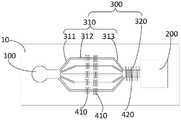
如图6所示,在一种示例性的实施例中,本发明提供的微流控芯片包括:As shown in FIG. 6, in an exemplary embodiment, the microfluidic chip provided by the present invention includes:
样本入口100;
样本废液收集口200;Sample waste
及连通于所述样本入口100与所述样本废液收集口200之间的样本微流道300;and a
其中,在所述样本微流道300内设置有至少一对微电极,所述至少一对微电极能够在待测样本通过所述样本微流道300时,产生信号变化以检测所述待测样本。Wherein, at least one pair of micro-electrodes is disposed in the
所述样本微流道300包括:The
用于检测待测样本内预定生物粒子数量的粒子计数区,所述粒子计数区包括从所述样本入口100分支出来、相互独立的多个分支微流道310,每一所述分支微流道310内设置至少一组微电极单元410,每组所述微电极单元410包括间隔设置的两个微电极,每组所述微电极单元410中的两个微电极均垂直于所述分支微流道310设置;A particle counting area for detecting the number of predetermined biological particles in the sample to be tested, the particle counting area includes a plurality of branched
以及,用于检测待测样本内预定抗体或抗原浓度的免疫检测区,所述免疫检测区包括汇合微流道320,所述汇合微流道320内设置有微电极阵列420,所述微电极阵列420的表面修饰有用于捕获所述预定抗体或抗原的辅助物,以使待测样本通过所述汇合微流道320时,所述待测样本内的所述预定抗体或抗原被所述辅助物捕获,所述微电极阵列420产生信号变化。And, an immunological detection area for detecting the concentration of a predetermined antibody or antigen in the sample to be tested, the immunological detection area includes a
上述示例性实施例中提供的微流控芯片,利用加工在芯片上分支微流道310及微电极单元410,来直接对流过微电极单元410上方的生物粒子进行计数;同时,利用加工在芯片上的汇合微流道320及微电极阵列420,来直接对流经微电极阵列420上方的抗原或抗体进行特异性捕获,实现免疫检测,这样,采用电学检测的方法,基于电化学阻抗检测法,省去了成本高昂的光学器件,简化设备,大大降低了检测成本,同时,在不增加成本和时间的前提下,将生物粒子计数与免疫检测集成在同一芯片上,仪器集成化程度高,满足了某些特定医疗场景的需求,丰富了产品的使用范围,使得仪器成本降低,且更加便携化;此外,可以一次进样进行两种分析(粒子数量分析和免疫检测分析),减少采样量,加快检测速度。The microfluidic chip provided in the above exemplary embodiment uses the branched
在本示例性的实施例中,如图6所示,所述粒子计数区的各所述分支微流道310的出口端汇合于所述汇合微流道320,且所述汇合微流道320连通于所述粒子计数区的多个所述分支微流道310与所述样本废液收集口200之间。In this exemplary embodiment, as shown in FIG. 6 , the outlet ends of each of the branched
采用上述方案,待测样本可从样本入口100先分支进入到粒子计数区的各分支微流道310对生物粒子进行计数,再汇合后进入免疫检测区的汇合微流道320进行免疫检测,最终样本废液流入至样本废液收集口200。With the above solution, the sample to be tested can be branched from the
需要说明的是,在上述实施例中,所述微流控芯片从所述样本入口100侧至所述样本废液收集口200侧,依次设置粒子计数区、免疫检测区,在其他实施例中,也可以是,所述微流控芯片从所述样本入口100侧至所述样本废液收集口200侧,依次设置免疫检测区、粒子计数区,也就是说,待测样本进入样本入口100之后,先汇合进行免疫检测,再分支至粒子计数区的各分支微流道310内进行生物粒子计数。It should be noted that, in the above embodiment, the microfluidic chip is provided with a particle counting area and an immune detection area in sequence from the
此外,在本实施例中,所述粒子计数区的微流道尺寸、微流道数量、微电极的尺寸及间距等参数的设定,可以与前述的示例性实施例中相同;所述免疫检测区的微流道尺寸、微流道数量、微电极的尺寸及间距等参数的设定,也可以与前述的示例性实施例中相同,在此均不再赘述。In addition, in this embodiment, the settings of parameters such as the size of the micro-channels, the number of micro-channels, the size and spacing of the micro-electrodes in the particle counting area can be the same as those in the foregoing exemplary embodiment; The settings of parameters such as the size of the micro-channels in the detection area, the number of micro-channels, the size and spacing of the micro-electrodes can also be the same as those in the foregoing exemplary embodiment, and will not be repeated here.
此外,本发明实施例中还提供了一种血细胞检测装置,包括:In addition, an embodiment of the present invention also provides a blood cell detection device, including:
本发明实施例所提供的微流控芯片;The microfluidic chip provided by the embodiment of the present invention;
样本流速控制机构,用于使得待测样本以预定流速通过所述微流控芯片上的所述样本微流道300;a sample flow rate control mechanism, configured to make the sample to be tested pass through the
及检测机构,电连接至所述微流控芯片上的所述微电极,用于检测所述微流控芯片的所述微电极的信号变化以检测所述待测样本。and a detection mechanism, which is electrically connected to the micro-electrodes on the micro-fluidic chip, and is used for detecting signal changes of the micro-electrodes of the micro-fluidic chip to detect the sample to be tested.
上述方案中,该微流控芯片应用于血细胞检测装置中,若实现血细胞检测,该检测装置还设置有样本流速控制机构,来使得待测样本进入样本入口100后,以预定流速流过各微流道,且还设置检测机构,以获取微电极的信号变化,从而可根据流速参数与信号变化参数相结合,实现对待测样本的检测。In the above solution, the microfluidic chip is used in a blood cell detection device. If blood cell detection is realized, the detection device is further provided with a sample flow rate control mechanism, so that after the sample to be tested enters the
在一种示例性的实施例中,所述样本流速控制机构包括:用于向所述样本入口100内的待测样本提供气压或者液压驱动力的气压或液压驱动单元。In an exemplary embodiment, the sample flow rate control mechanism includes: a pneumatic or hydraulic driving unit for providing a pneumatic or hydraulic driving force to the sample to be tested in the
采用上述方案,可以利用气压或液压方式来驱动待测样本在各微流道内以预定速度从样本入口100向样本废液收集口200进行流动,且对于流速控制,可以通过调节气压或液压即可实现,具有操作方便,控制精确的优点。对于所述气压或液压驱动单元的具体结构,在此并不进行限定,不再详细赘述。With the above solution, the sample to be tested can be driven by air pressure or hydraulic pressure to flow from the
还需要说明的是,所述样本流速控制机构也还可以采用除气压或液压驱动方式之外的其他方式来驱动待测样本流动,例如,还可以利用重力等方式来驱动待测样本流动。It should also be noted that the sample flow rate control mechanism can also use other methods other than pneumatic or hydraulic driving to drive the flow of the sample to be tested, for example, gravity and other methods can also be used to drive the flow of the sample to be tested.
此外,在一种示例性的实施例中,所述检测机构包括第一电源、第一电阻及第一检测器;所述第一电源的一端电连接至每组所述微电极单元410中的一个微电极,所述第一电源的另一端通过所述电阻电连接至每组所述微电极单元410中的另一微电极上,所述第一检测器与每组所述微电极单元410中的两个微电极相连。In addition, in an exemplary embodiment, the detection mechanism includes a first power source, a first resistor, and a first detector; one end of the first power source is electrically connected to each group of the microelectrode units 410 a micro-electrode, the other end of the first power supply is electrically connected to the other micro-electrode in each group of the
采用上述方案,当待测样本的生物粒子一个个通过分支微流道310时,各微电极单元410中的两个微电极之间的电压发生改变,第一检测器可以通过检测两个微电极之间的电压变化来测量生物粒子体积大小,以实现粒子计数。另外,需要说明的是,各分支微流道310可以共用第一电源及第一检测器,但通常需要分别配置第一电阻。With the above solution, when the biological particles of the sample to be tested pass through the branch microchannels 310 one by one, the voltage between the two microelectrodes in each
此外,在一种示例性的实施例中,当所述微流控芯片包括粒子计数区,且每一所述分支微流道310内设置有至少2个所述微电极单元410时,如图7所示,所述第一检测器包括:In addition, in an exemplary embodiment, when the microfluidic chip includes a particle counting area, and each of the branched
第一接收器,用于接收每一所述微电极单元410的信号;a first receiver for receiving signals from each of the
第一比较器,用于比较同一所述分支微流道310内的至少2个所述微电极单元410的信号;a first comparator, configured to compare the signals of at least two of the
第一判断器,用于当同一所述分支微流道310内的至少2个所述微电极单元410的信号差值在阈值内时,判断检测结果准确;当同一所述分支微流道310内的至少2个所述微电极单元410的信号差值在阈值外时,判断检测结果不准确;The first determiner is used to determine that the detection result is accurate when the signal difference of at least two of the
第一计算器,用于当所述第一判断器所判断的检测结果准确时,根据所述a first calculator, configured to, when the detection result judged by the first judger is accurate, calculate according to the
第一接收器所接收的信号变化,计算所述预定生物粒子的数量。The signal received by the first receiver varies, and the number of the predetermined biological particles is calculated.
采用上述方案,当各分支微流道310所对应的微电极单元410有至少两组时,每组微电极单元410所获取的信号差值在阈值内时,则第一检测器判断检测结果误差不大,结果准确,而当每组微电极单元410所获取的信号差值在阈值外时,则第一检测器判断检测结果误差大,结果不准确,如此,可减少由于操作失误等原因造成的误差大,检测结果不准确的问题,进一步提高检测准确性。With the above solution, when there are at least two groups of
此外,在一种示例性的实施例中,当所述微流控芯片包括免疫检测区时,所述检测机构包括第二电源、第二电阻以及第二检测器;所述第二电源的一端电连接至所述微电极阵列420中的一个微电极,所述第二电源的另一端通过所述电阻电连接至所述微电极阵列420中的另一微电极上,所述第二检测器与所述微电极阵列420中的两个微电极相连;其中,所述第二检测器包括:In addition, in an exemplary embodiment, when the microfluidic chip includes an immune detection area, the detection mechanism includes a second power supply, a second resistor and a second detector; one end of the second power supply is electrically connected to one microelectrode in the
第二接收器,用于接收所述微电极阵列420的信号;a second receiver, configured to receive the signal of the
第二计算器,用于根据所述第二接收器所接收的信号变化,计算所述预定抗体或抗原的浓度。The second calculator is used for calculating the concentration of the predetermined antibody or antigen according to the change of the signal received by the second receiver.
采用上述方案,当待测样本通过汇合微流道320时,微电极阵列420中的各微电极之间的电压发生改变,第二检测器可以通过检测各微电极之间的电压变化来测量抗体或抗原的浓度,以实现免疫检测。With the above solution, when the sample to be tested passes through the
以下对该集成有粒子计数功能和免疫检测功能的微流控芯片,应用于该血细胞检测装置中时的使用方式进行举例说明:The following is an example of how the microfluidic chip with integrated particle counting function and immune detection function is applied to the blood cell detection device:
首先需要说明的是,发炎是一种很常见的症状,炎症的初步检测与诊断一般需要检测血液中三种不同白细胞的数量,据此来判断病人感染的类型;同时,如果是细菌性的感染,血液中的C反应蛋白(CRP)浓度也会有相应的提升。因此,炎症的初筛常常需要将白细胞计数与CRP浓度检测(一种免疫检测)结合进行。First of all, it should be noted that inflammation is a very common symptom. The initial detection and diagnosis of inflammation generally requires the detection of the number of three different white blood cells in the blood to determine the type of infection of the patient; at the same time, if it is a bacterial infection , the blood C-reactive protein (CRP) concentration will also have a corresponding increase. Therefore, primary screening for inflammation often requires a combination of white blood cell counts and CRP concentration detection, an immunoassay.
下面以同时实现白细胞三分类计数与CRP浓度检测为例,说明本实施例中集成有粒子计数功能和免疫检测功能的微流控芯片的实施方式:The implementation of the microfluidic chip integrated with the particle counting function and the immune detection function in this embodiment is described below by taking the realization of the three-classification counting of white blood cells and the detection of CRP concentration as an example:
预处理后的待测样本由所述样本入口100进入该微流控芯片,首先流经粒子计数区,进入各分支微流道310,由于粒子计数区由多个独立的分支微通道组成,每个分支微通道的宽度与深度为稍稍大于单个白细胞的尺寸,这样,保证单细胞流的形成,当待测样本流经各分支微流道310内的微电极之间时,会产生一个阻抗信号的变化,第一检测器即根据不同大小和不同结构细胞产生的阻抗信号不同,来对不同类型的细胞进行区分和计数,对白细胞进行计数;The preprocessed sample to be tested enters the microfluidic chip through the
然后,待测样本经过粒子计数区后再次汇聚,进入免疫检测区的汇合微流道320,由于汇合微流道320内的微电极阵列420的表面会预先修饰CRP捕获抗体,当待测样本中的CRP流经微电极附近时,会被CRP捕获抗体捕获,进而在微电极间产生阻抗信号的变化,由于不同浓度的CRP样本,产生的阻抗信号大小会有很大差异,据此,第二检测器可以实现CRP的定量分析;Then, the sample to be tested passes through the particle counting area and converges again, and enters the
最后,检测后的样本流入样本废液收集口200,全部检测完成。Finally, the detected sample flows into the sample waste
有以下几点需要说明:The following points need to be noted:
(1)本公开实施例附图只涉及到与本公开实施例涉及到的结构,其他结构可参考通常设计。(1) The accompanying drawings of the embodiments of the present disclosure only relate to the structures involved in the embodiments of the present disclosure, and other structures may refer to general designs.
(2)为了清晰起见,在用于描述本公开的实施例的附图中,层或区域的厚度被放大或缩小,即这些附图并非按照实际的比例绘制。可以理解,当诸如层、膜、区域或基板之类的元件被称作位于另一元件“上”或“下”时,该元件可以“直接”位于另一元件“上”或“下”或者可以存在中间元件。(2) In the drawings for describing the embodiments of the present disclosure, the thicknesses of layers or regions are exaggerated or reduced for clarity, ie, the drawings are not drawn on actual scale. It will be understood that when an element such as a layer, film, region or substrate is referred to as being "on" or "under" another element, it can be "directly on" or "under" the other element, or Intermediate elements may be present.
(3)在不冲突的情况下,本公开的实施例及实施例中的特征可以相互组合以得到新的实施例。(3) The embodiments of the present disclosure and the features in the embodiments may be combined with each other to obtain new embodiments without conflict.
以上所述,仅为本公开的具体实施方式,但本公开的保护范围并不局限于此,本公开的保护范围应以权利要求的保护范围为准。The above descriptions are only specific embodiments of the present disclosure, but the protection scope of the present disclosure is not limited thereto, and the protection scope of the present disclosure should be subject to the protection scope of the claims.
Claims (12)
Translated fromChinesePriority Applications (1)
| Application Number | Priority Date | Filing Date | Title |
|---|---|---|---|
| CN201910917654.3ACN112547143B (en) | 2019-09-26 | 2019-09-26 | Micro-fluidic chip and blood cell detection device |
Applications Claiming Priority (1)
| Application Number | Priority Date | Filing Date | Title |
|---|---|---|---|
| CN201910917654.3ACN112547143B (en) | 2019-09-26 | 2019-09-26 | Micro-fluidic chip and blood cell detection device |
Publications (2)
| Publication Number | Publication Date |
|---|---|
| CN112547143A CN112547143A (en) | 2021-03-26 |
| CN112547143Btrue CN112547143B (en) | 2022-07-22 |
Family
ID=75029922
Family Applications (1)
| Application Number | Title | Priority Date | Filing Date |
|---|---|---|---|
| CN201910917654.3AActiveCN112547143B (en) | 2019-09-26 | 2019-09-26 | Micro-fluidic chip and blood cell detection device |
Country Status (1)
| Country | Link |
|---|---|
| CN (1) | CN112547143B (en) |
Families Citing this family (3)
| Publication number | Priority date | Publication date | Assignee | Title |
|---|---|---|---|---|
| CN115248327A (en)* | 2021-04-26 | 2022-10-28 | 深圳市帝迈生物技术有限公司 | POCT blood cell analyzer, kit |
| CN113552298A (en)* | 2021-08-23 | 2021-10-26 | 湖南山水检测有限公司 | Method for detecting antibiotic residual quantity in animal-derived food |
| CN115109699A (en)* | 2022-05-20 | 2022-09-27 | 中国科学院上海微系统与信息技术研究所 | Organ chip with integrated microelectrode array and method of making and using the same |
Citations (7)
| Publication number | Priority date | Publication date | Assignee | Title |
|---|---|---|---|---|
| CN101528942A (en)* | 2006-09-01 | 2009-09-09 | 阿肯色大学评议会 | Methods and systems for detection of contaminants |
| CN101620228A (en)* | 2009-07-12 | 2010-01-06 | 宁波大学 | Special AIDS diagnosis device combining and utilizing high polymer anoxybiotic pyrolysis product |
| CN103084229A (en)* | 2012-01-16 | 2013-05-08 | 中国科学院深圳先进技术研究院 | Micro-fluidic chip, hemocyte analysis system and hemocyte analysis method |
| CN103907025A (en)* | 2011-04-01 | 2014-07-02 | 哈佛大学校长及研究员协会 | Dialysis like therapeutic (DLT) device |
| CN104165906A (en)* | 2014-07-14 | 2014-11-26 | 中国农业大学 | Virus detector |
| CN105728069A (en)* | 2016-01-30 | 2016-07-06 | 深圳市贝沃德克生物技术研究院有限公司 | Multi-channel micro-fluidic chip for rapid blood self-inspection |
| CN109752307A (en)* | 2017-11-03 | 2019-05-14 | 夏普生命科学(欧洲)有限公司 | Coplanar micro- impedance blood count equipment |
- 2019
- 2019-09-26CNCN201910917654.3Apatent/CN112547143B/enactiveActive
Patent Citations (7)
| Publication number | Priority date | Publication date | Assignee | Title |
|---|---|---|---|---|
| CN101528942A (en)* | 2006-09-01 | 2009-09-09 | 阿肯色大学评议会 | Methods and systems for detection of contaminants |
| CN101620228A (en)* | 2009-07-12 | 2010-01-06 | 宁波大学 | Special AIDS diagnosis device combining and utilizing high polymer anoxybiotic pyrolysis product |
| CN103907025A (en)* | 2011-04-01 | 2014-07-02 | 哈佛大学校长及研究员协会 | Dialysis like therapeutic (DLT) device |
| CN103084229A (en)* | 2012-01-16 | 2013-05-08 | 中国科学院深圳先进技术研究院 | Micro-fluidic chip, hemocyte analysis system and hemocyte analysis method |
| CN104165906A (en)* | 2014-07-14 | 2014-11-26 | 中国农业大学 | Virus detector |
| CN105728069A (en)* | 2016-01-30 | 2016-07-06 | 深圳市贝沃德克生物技术研究院有限公司 | Multi-channel micro-fluidic chip for rapid blood self-inspection |
| CN109752307A (en)* | 2017-11-03 | 2019-05-14 | 夏普生命科学(欧洲)有限公司 | Coplanar micro- impedance blood count equipment |
Also Published As
| Publication number | Publication date |
|---|---|
| CN112547143A (en) | 2021-03-26 |
Similar Documents
| Publication | Publication Date | Title |
|---|---|---|
| US10527568B2 (en) | Counting particles using an electrical differential counter | |
| Vembadi et al. | Cell cytometry: review and perspective on biotechnological advances | |
| CN103439241B (en) | The fluidic chip detecting system that unicellular multiparameter characterizes | |
| Hassan et al. | A microfluidic biochip for complete blood cell counts at the point-of-care | |
| CN103923825B (en) | A microfluidic chip system integrating cell sorting and detection | |
| Spencer et al. | A sheath-less combined optical and impedance micro-cytometer | |
| CN103170377B (en) | Hemocyte analysis chip and system for using chip thereof | |
| US8963095B2 (en) | Electrokinetic microfluidic flow cytometer apparatuses with differential resistive particle counting and optical sorting | |
| CN112547143B (en) | Micro-fluidic chip and blood cell detection device | |
| CN103084229B (en) | Micro-fluidic chip, blood cell analysis system and blood cell analysis method | |
| WO2011049718A1 (en) | Electrokinetic microfluidic flow cytometer apparatuses with differential resistive particle counting and optical sorting | |
| CN104941704A (en) | Method for integrating focusing and detection of cells and miniaturized system thereof | |
| CN103471980B (en) | A kind of chip type blood cell analyzer and method | |
| Xie et al. | Particle self-aligning, focusing, and electric impedance microcytometer device for label-free single cell morphology discrimination and yeast budding analysis | |
| Emaminejad et al. | Portable cytometry using microscale electronic sensing | |
| Hosseini et al. | Low-cost sheath-less microfluidic impedance cytometry for point-of-care applications | |
| CN109939751B (en) | Microfluidic chip, detection device and detection method for whole blood detection | |
| CN208642692U (en) | A kind of micro-fluidic chip | |
| CN207020078U (en) | A kind of plasmon waveguide, bio-sensing chip and system | |
| CN113804877B (en) | Microfluidic analysis chip and sample detection method | |
| Chapman et al. | Label-free resistive-pulse cytometry | |
| US20250012704A1 (en) | Microfluidic cartridge and methods of use thereof | |
| TW504491B (en) | Chip-type device for counting/classifying and analyzing the micro-fluid particle and manufacturing method thereof | |
| Shi et al. | Leukocyte count and two-part differential in whole blood based on a portable microflow cytometer | |
| Cheng et al. | Microchip-based impedance flow cell analyzer |
Legal Events
| Date | Code | Title | Description |
|---|---|---|---|
| PB01 | Publication | ||
| PB01 | Publication | ||
| SE01 | Entry into force of request for substantive examination | ||
| SE01 | Entry into force of request for substantive examination | ||
| GR01 | Patent grant | ||
| GR01 | Patent grant |