CN112545889B - Western medicine working device that dispenses - Google Patents
Western medicine working device that dispensesDownload PDFInfo
- Publication number
- CN112545889B CN112545889BCN202011412121.9ACN202011412121ACN112545889BCN 112545889 BCN112545889 BCN 112545889BCN 202011412121 ACN202011412121 ACN 202011412121ACN 112545889 BCN112545889 BCN 112545889B
- Authority
- CN
- China
- Prior art keywords
- medicine
- rod
- threaded rod
- gear
- cavity
- Prior art date
- Legal status (The legal status is an assumption and is not a legal conclusion. Google has not performed a legal analysis and makes no representation as to the accuracy of the status listed.)
- Expired - Fee Related
Links
Images


Classifications
- A—HUMAN NECESSITIES
- A61—MEDICAL OR VETERINARY SCIENCE; HYGIENE
- A61J—CONTAINERS SPECIALLY ADAPTED FOR MEDICAL OR PHARMACEUTICAL PURPOSES; DEVICES OR METHODS SPECIALLY ADAPTED FOR BRINGING PHARMACEUTICAL PRODUCTS INTO PARTICULAR PHYSICAL OR ADMINISTERING FORMS; DEVICES FOR ADMINISTERING FOOD OR MEDICINES ORALLY; BABY COMFORTERS; DEVICES FOR RECEIVING SPITTLE
- A61J1/00—Containers specially adapted for medical or pharmaceutical purposes
- A61J1/14—Details; Accessories therefor
- A61J1/20—Arrangements for transferring or mixing fluids, e.g. from vial to syringe
- A61J1/2003—Accessories used in combination with means for transfer or mixing of fluids, e.g. for activating fluid flow, separating fluids, filtering fluid or venting
- A61J1/2006—Piercing means
- A61J1/2013—Piercing means having two piercing ends
- A—HUMAN NECESSITIES
- A61—MEDICAL OR VETERINARY SCIENCE; HYGIENE
- A61J—CONTAINERS SPECIALLY ADAPTED FOR MEDICAL OR PHARMACEUTICAL PURPOSES; DEVICES OR METHODS SPECIALLY ADAPTED FOR BRINGING PHARMACEUTICAL PRODUCTS INTO PARTICULAR PHYSICAL OR ADMINISTERING FORMS; DEVICES FOR ADMINISTERING FOOD OR MEDICINES ORALLY; BABY COMFORTERS; DEVICES FOR RECEIVING SPITTLE
- A61J1/00—Containers specially adapted for medical or pharmaceutical purposes
- A61J1/14—Details; Accessories therefor
- A61J1/20—Arrangements for transferring or mixing fluids, e.g. from vial to syringe
- A61J1/2003—Accessories used in combination with means for transfer or mixing of fluids, e.g. for activating fluid flow, separating fluids, filtering fluid or venting
- A61J1/202—Separating means
- A61J1/2041—Separating means having removable plugs
- A—HUMAN NECESSITIES
- A61—MEDICAL OR VETERINARY SCIENCE; HYGIENE
- A61J—CONTAINERS SPECIALLY ADAPTED FOR MEDICAL OR PHARMACEUTICAL PURPOSES; DEVICES OR METHODS SPECIALLY ADAPTED FOR BRINGING PHARMACEUTICAL PRODUCTS INTO PARTICULAR PHYSICAL OR ADMINISTERING FORMS; DEVICES FOR ADMINISTERING FOOD OR MEDICINES ORALLY; BABY COMFORTERS; DEVICES FOR RECEIVING SPITTLE
- A61J1/00—Containers specially adapted for medical or pharmaceutical purposes
- A61J1/14—Details; Accessories therefor
- A61J1/20—Arrangements for transferring or mixing fluids, e.g. from vial to syringe
- A61J1/2003—Accessories used in combination with means for transfer or mixing of fluids, e.g. for activating fluid flow, separating fluids, filtering fluid or venting
- A61J1/2048—Connecting means
- A61J1/2055—Connecting means having gripping means
Landscapes
- Health & Medical Sciences (AREA)
- Physics & Mathematics (AREA)
- Fluid Mechanics (AREA)
- Pharmacology & Pharmacy (AREA)
- Life Sciences & Earth Sciences (AREA)
- Animal Behavior & Ethology (AREA)
- General Health & Medical Sciences (AREA)
- Public Health (AREA)
- Veterinary Medicine (AREA)
- Reciprocating Pumps (AREA)
- Medical Preparation Storing Or Oral Administration Devices (AREA)
Abstract
Description
Translated fromChinese技术领域technical field
本发明涉及配药设备领域,具体为一种西药配药工作装置。The invention relates to the field of dispensing equipment, in particular to a western medicine dispensing working device.
背景技术Background technique
输液或大容量注射液,是指由静脉滴注输入体内的大剂量注射液,一次给药在100ml以上。它是注射剂的一个分支,通常包装在玻璃或塑料的输液瓶或袋中,不含抑菌剂。使用时通过输液器调整滴速,持续而稳定地将药物输入体内,而在输液前需要将使用的药液按一定比例配制成混合溶液。Infusion or large-volume injection refers to a large-dose injection that is injected into the body by intravenous drip, with a single dose of more than 100ml. It is an offshoot of injectables, usually packaged in glass or plastic infusion bottles or bags, without bacteriostatic agents. When in use, the dripping speed is adjusted by the infusion device, and the drug is continuously and stably infused into the body, and the used drug solution needs to be prepared into a mixed solution in a certain proportion before the infusion.
目前常用的配药方式都是利用针筒将配药的药液抽出后再注入到药瓶中,如果药量过大,则工作过程十分繁琐,并且很容易在操作中误触针筒的活塞杆,继而将细菌通过活塞杆带入到针筒内部,而且长时间操作容易疲劳,并且工作效率也不高。At present, the commonly used method of dispensing is to use the syringe to draw out the medicine liquid and then inject it into the medicine bottle. If the amount of medicine is too large, the working process is very complicated, and it is easy to accidentally touch the piston rod of the syringe during operation. Then the bacteria are brought into the inside of the syringe through the piston rod, and the long-term operation is easy to fatigue, and the work efficiency is not high.
发明内容SUMMARY OF THE INVENTION
针对现有技术的不足,本发明提供了一种西药配药工作装置,具有提高医护人员的配药效率的优点,解决了背景技术提出的问题。Aiming at the deficiencies of the prior art, the present invention provides a western medicine dispensing working device, which has the advantages of improving the dispensing efficiency of medical staff and solves the problems raised by the background technology.
为实现上述目的,本发明提供如下技术方案:一种西药配药工作装置,包括底座,所述底座的顶端设置有一号螺纹杆,且一号螺纹杆的外壁设置有一号套管,所述一号螺纹杆的表面螺纹连接有二号螺纹杆,且二号螺纹杆的一端设置有一号齿轮,所述一号套管的顶端设置有支架,且支架的顶端设置有箱体,所述箱体的内部设置有空腔,且空腔内部套接有推杆,所述空腔的一侧连通有出料管,所述箱体的底端水平设置有二号套管,且二号套管的内腔螺纹连接有三号螺纹杆,所述三号螺纹杆的一端通过轴承与推杆的一端连接,所述二号套管的另一端设置有转动杆,且转动杆的另一端设置有固定在箱体一侧的电机,所述转动杆的表面设置有可水平移动的二号齿轮,且二号齿轮与一号齿轮为啮合连接,所述空腔的一侧贯穿有取药管且延伸至箱体的外部,所述取药管的另一端设置有取药装置。In order to achieve the above purpose, the present invention provides the following technical solutions: a western medicine dispensing working device, comprising a base, the top of the base is provided with a No. 1 threaded rod, and the outer wall of the No. 1 threaded rod is provided with a No. The surface of the threaded rod is threadedly connected with a No. 2 threaded rod, and one end of the No. 2 threaded rod is provided with a No. 1 gear, the top of the No. 1 sleeve is provided with a bracket, and the top of the bracket is provided with a box body, the A cavity is provided inside, and a push rod is sleeved inside the cavity, one side of the cavity is communicated with a discharge pipe, and the bottom end of the box is horizontally provided with a No. The inner cavity is threadedly connected with a No. 3 threaded rod, one end of the No. 3 threaded rod is connected with one end of the push rod through a bearing, the other end of the No. 2 sleeve is provided with a rotating rod, and the other end of the rotating rod is provided with a fixed The motor on one side of the box body, the surface of the rotating rod is provided with a No. 2 gear that can move horizontally, and the No. 2 gear is meshed with the No. 1 gear, and one side of the cavity has a medicine-taking tube extending to the Outside the box, the other end of the medicine taking tube is provided with a medicine taking device.
优选的,所述出料管的表面设置有单向阀,且出料管的另一端设置有一号接头,所述一号接头一端螺纹连接有二号接头,且二号接头的另一端连通有导管。Preferably, the surface of the discharge pipe is provided with a one-way valve, and the other end of the discharge pipe is provided with a No. 1 joint, one end of the No. 1 joint is screwed with a No. 2 joint, and the other end of the No. 2 joint is connected with a No. 2 joint. catheter.
优选的,所述箱体的底端设置有套环,且套环与二号套管构成活动连接。Preferably, the bottom end of the box body is provided with a collar, and the collar is movably connected with the No. 2 sleeve.
优选的,所述转动杆的外壁开设有滑槽,所述二号齿轮的一侧设置有支板,且支板的表面通过开槽活动连接有限位杆,所述滑槽的内部底端开设有限位槽。Preferably, the outer wall of the rotating rod is provided with a chute, one side of the No. 2 gear is provided with a support plate, and the surface of the support plate is movably connected to the limit rod through the slot, and the inner bottom end of the chute is provided with a support plate. limited slot.
优选的,所述滑槽与限位杆构成滑动连接,所述限位杆与限位槽为螺纹连接。Preferably, the sliding groove and the limit rod form a sliding connection, and the limit rod and the limit groove are threadedly connected.
优选的,所述取药装置的内部包括有与取药管的一端为螺纹连接有三通接头,且三通接头的表面设置有若干取药器。Preferably, the inside of the medicine-taking device includes a tee joint that is threadedly connected to one end of the medicine-taking tube, and the surface of the tee joint is provided with several medicine takers.
优选的,所述底座的顶端安装有固定机构,且固定机构的内部包括有分别对应设置在底座顶端的一号立板和二号立板,所述一号立板的表面设置有可移动的四号螺纹杆,且四号螺纹杆的另一端设置有夹板。Preferably, a fixing mechanism is installed on the top of the base, and the interior of the fixing mechanism includes a No. 1 vertical plate and a No. 2 vertical plate respectively arranged on the top of the base, and the surface of the No. 1 vertical plate is provided with movable No. 4 threaded rod, and the other end of the No. 4 threaded rod is provided with a splint.
优选的,所述取药装置位于固定机构的正上方,所述箱体的外壁设置有玻璃窗,且玻璃窗的表面设置有刻度线。Preferably, the medicine taking device is located directly above the fixing mechanism, the outer wall of the box body is provided with a glass window, and the surface of the glass window is provided with scale lines.
一种西药配药工作装置的使用方法,其使用步骤如下:A method of using a western medicine dispensing working device, the steps of which are as follows:
S1.首先将储药袋放置在一号立板与二号立板之间,通过转动四号螺纹杆,使得夹板对储药袋进行固定,再将取药器插入需要取药的药袋内,S1. First, place the medicine storage bag between the No. 1 vertical plate and the No. 2 vertical plate, turn the No. 4 threaded rod to fix the medicine storage bag with the splint, and then insert the medicine dispenser into the medicine bag that needs to be taken. ,
S2.然后启动电机,使得电机带动转动杆顺时针转动,转动杆带动二号套管顺时针转动,从而使得三号螺纹杆带动推杆向右移动,此时取药器将药袋内的药液通过取药管输送至空腔,同时位于空腔的药液通过出料管输送至一号接头与二号接头处,且转动杆转动的同时,二号齿轮带动一号齿轮转动,使得二号螺纹杆带动一号螺纹杆在一号套管内升降移动,从而使得推杆抽取药液时,出料管随着推杆的左右移动而上下移动,避免出料管的高度为固定式,导致滴落至储药袋内的药液产生迸溅,S2. Then start the motor, so that the motor drives the rotating rod to rotate clockwise, and the rotating rod drives the No. 2 casing to rotate clockwise, so that the No. 3 threaded rod drives the push rod to move to the right. At this time, the medicine dispenser removes the medicine in the medicine bag The liquid is transported to the cavity through the medicine taking tube, and the medicine liquid in the cavity is transported to the No. 1 joint and No. 2 joint through the discharge pipe, and when the rotating rod rotates, the No. 2 gear drives the No. 1 gear to rotate, so that the second The No. 1 threaded rod drives the No. 1 threaded rod to move up and down in the No. 1 casing, so that when the push rod extracts the liquid, the discharge pipe moves up and down with the left and right movement of the push rod, so as to avoid the height of the discharge pipe being fixed, resulting in The liquid dripping into the medicine storage bag produces a splash,
S3.若需要将出料管的高度设置为固定式,通过转动限位杆,使得限位杆与限位槽分离,此时可通过滑槽来移动二号齿轮,使得二号齿轮与一号齿轮分离,此时电机转动时并不会使得二号齿轮带动一号齿轮转动。S3. If it is necessary to set the height of the discharge pipe to be fixed, turn the limit rod to separate the limit rod from the limit groove. At this time, the No. 2 gear can be moved through the chute, so that the No. 2 gear and No. 1 The gears are separated. At this time, when the motor rotates, the No. 2 gear will not drive the No. 1 gear to rotate.
与现有技术对比,本发明具备以下有益效果:Compared with the prior art, the present invention has the following beneficial effects:
1.本发明中,通过电机带动转动杆顺时针转动,转动杆带动二号套管顺时针转动,从而使得三号螺纹杆带动推杆向右移动,此时取药器将药袋内的药液通过取药管输送至空腔,同时位于空腔的药液通过出料管输送至一号接头与二号接头处,且转动杆转动的同时,二号齿轮带动一号齿轮转动,使得二号螺纹杆带动一号螺纹杆在一号套管内升降移动,从而使得推杆抽取药液时,出料管随着推杆的左右移动而上下移动,避免出料管的高度为固定式,导致滴落至储药袋内的药液产生迸溅,实现最大程度减少医护人员的参与度,提高配药效率,且减少药液或者器械的污染。1. In the present invention, the rotating rod is driven to rotate clockwise by the motor, and the rotating rod drives the No. 2 casing to rotate clockwise, so that the No. 3 threaded rod drives the push rod to move to the right, and the medicine taker removes the medicine in the medicine bag. The liquid is transported to the cavity through the medicine taking tube, and the medicine liquid located in the cavity is transported to the No. 1 joint and No. 2 joint through the discharge pipe, and when the rotating rod rotates, the No. 2 gear drives the No. 1 gear to rotate, so that the second The No. 1 threaded rod drives the No. 1 threaded rod to move up and down in the No. 1 casing, so that when the push rod extracts the liquid, the discharge pipe moves up and down with the left and right movement of the push rod, so as to avoid the height of the discharge pipe being fixed, resulting in The medicinal liquid dripped into the medicine storage bag will splash, which can minimize the participation of medical staff, improve the dispensing efficiency, and reduce the pollution of medicinal liquid or equipment.
2.本发明中,通过转动限位杆,使得限位杆与限位槽分离,此时可通过滑槽来移动二号齿轮,使得二号齿轮与一号齿轮分离,此时电机转动时并不会使得二号齿轮带动一号齿轮转动,使得出料管的高度固定,从而使得该装置能够对不同的储药袋进行配药工作,满足不同的使用需求,提高适用性。2. In the present invention, by rotating the limit rod, the limit rod is separated from the limit groove. At this time, the No. 2 gear can be moved through the chute, so that the No. 2 gear and the No. 1 gear are separated. The No. 2 gear will not drive the No. 1 gear to rotate, so that the height of the discharge pipe is fixed, so that the device can dispense medicines to different medicine storage bags, meet different usage requirements and improve applicability.
附图说明Description of drawings
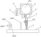
图1为本发明中一种西药配药工作装置整体结构示意图;Fig. 1 is the overall structure schematic diagram of a kind of western medicine dispensing working device in the present invention;
图2为本发明的左侧结构示意图;Fig. 2 is the left side structure schematic diagram of the present invention;
图3为图2中A处的放大结构示意图;Fig. 3 is the enlarged structure schematic diagram of A place in Fig. 2;
图4本发明中转动杆和二号齿轮的结构示意图;Figure 4 is a schematic structural diagram of the rotating rod and the No. 2 gear in the present invention;
图5为本发明中转动杆和二号齿轮的剖面结构示意图;Fig. 5 is the sectional structure schematic diagram of the rotating rod and the second gear in the present invention;
图6为本发明中箱体的表面结构示意图。FIG. 6 is a schematic diagram of the surface structure of the box in the present invention.
图中:1.底座;2.一号螺纹杆;201、二号螺纹杆;3.一号套管;4.一号齿轮;5.支架;6.箱体;601.空腔;602.套环;603.玻璃窗;7.推杆;8.出料管;801.单向阀;802.一号接头;803.二号接头;804.导管;9.二号套管;10.三号螺纹杆;11.转动杆;1101.滑槽;1102.限位槽;12.电机;13.二号齿轮;1301.支板;1302.限位杆;14.取药管;15.取药装置;1501.三通接头;1502.取药器;16.固定机构;1601.一号立板;1602.二号立板;1603.四号螺纹杆;1604.夹板。In the figure: 1. Base; 2. No. 1 threaded rod; 201, No. 2 threaded rod; 3. No. 1 casing; 4. No. 1 gear; 5. Bracket; 6. Box; 601. Cavity; 602. 603. Glass window; 7. Push rod; 8. Discharge pipe; 801. Check valve; 802. No. 1 joint; 803. No. 2 joint; 804. Conduit; 9. No. 2 casing; 10. No. 3 threaded rod; 11. Rotating rod; 1101. Chute; 1102. Limit slot; 12. Motor; 13. No. 2 gear; 1301. Support plate; 1302. Limit rod; Medicine taking device; 1501. Tee joint; 1502. Medicine taking device; 16. Fixing mechanism; 1601. No. 1 vertical plate; 1602. No. 2 vertical plate; 1603. No. 4 threaded rod;
具体实施方式Detailed ways
下面将结合本发明实施例中的附图,对本发明实施例中的技术方案进行清楚、完整地描述,显然,所描述的实施例仅仅是本发明一部分实施例,而不是全部的实施例。基于本发明中的实施例,本领域普通技术人员在没有做出创造性劳动前提下所获得的所有其他实施例,都属于本发明保护的范围。The technical solutions in the embodiments of the present invention will be clearly and completely described below with reference to the accompanying drawings in the embodiments of the present invention. Obviously, the described embodiments are only a part of the embodiments of the present invention, but not all of the embodiments. Based on the embodiments of the present invention, all other embodiments obtained by those of ordinary skill in the art without creative efforts shall fall within the protection scope of the present invention.
请参阅图1-6,一种西药配药工作装置,包括底座1,底座1的顶端设置有一号螺纹杆2,且一号螺纹杆2的外壁设置有一号套管3,一号螺纹杆2的表面螺纹连接有二号螺纹杆201,且二号螺纹杆201的一端设置有一号齿轮4,一号套管3的顶端设置有支架5,且支架5的顶端设置有箱体6,箱体6的内部设置有空腔601,且空腔601内部套接有推杆7,空腔601的一侧连通有出料管8,箱体6的底端水平设置有二号套管9,且二号套管9的内腔螺纹连接有三号螺纹杆10,三号螺纹杆10的一端通过轴承与推杆7的一端连接,二号套管9的另一端设置有转动杆11,且转动杆11的另一端设置有固定在箱体6一侧的电机12,转动杆11的表面设置有可水平移动的二号齿轮13,且二号齿轮13与一号齿轮4为啮合连接,空腔601的一侧贯穿有取药管14且延伸至箱体6的外部,取药管14的另一端设置有取药装置15。1-6, a western medicine dispensing working device includes a base 1, the top of the base 1 is provided with a No. 1 threaded rod 2, and the outer wall of the No. 1 threaded rod 2 is provided with a No. The surface is screwed with a No. 2 threaded
具体的,出料管8的表面设置有单向阀801,且出料管8的另一端设置有一号接头802,一号接头802一端螺纹连接有二号接头803,且二号接头803的另一端连通有导管804,单向阀801可避免出料管8内的药液回流,一号接头802与二号接头803可进行拆卸或者更换其他型号的管道。Specifically, the surface of the
具体的,箱体6的底端设置有套环602,且套环602与二号套管9构成活动连接,这样便于二号套管9进行转动。Specifically, the bottom end of the
具体的,转动杆11的外壁开设有滑槽1101,二号齿轮13的一侧设置有支板1301,且支板1301的表面通过开槽活动连接有限位杆1302,滑槽1101的内部底端开设有限位槽1102,通过转动限位杆1302,使得限位杆1302与限位槽1102分离,此时可通过滑槽1101来移动二号齿轮13,使得二号齿轮13与一号齿轮4分离,此时电机12转动时并不会使得二号齿轮13带动一号齿轮4转动,使得出料管8的高度固定,从而使得该装置能够对不同的储药袋或者储药瓶进行配药工作,满足不同的使用需求,提高适用性。Specifically, the outer wall of the
具体的,滑槽1101与限位杆1302构成滑动连接,限位杆1302与限位槽1102为螺纹连接,通过转动限位杆1302,使得限位杆1302与限位槽1102螺纹固定,使得二号齿轮13固定在转动杆11上。Specifically, the
具体的,取药装置15的内部包括有与取药管14的一端为螺纹连接有三通接头1501,且三通接头1501的表面设置有若干取药器1502,取药器1502包括但不限于钢针等器械。Specifically, the inside of the
具体的,底座1的顶端安装有固定机构16,且固定机构16的内部包括有分别对应设置在底座1顶端的一号立板1601和二号立板1602,一号立板1601的表面设置有可移动的四号螺纹杆1603,且四号螺纹杆1603的另一端设置有夹板1604,通过转动四号螺纹杆1603,使得夹板1604对或者储药瓶进行固定。Specifically, a
具体的,取药装置15位于固定机构16的正上方,箱体6的外壁设置有玻璃窗603,且玻璃窗603的表面设置有刻度线,玻璃窗603和刻度线便于使用者清楚抽取药液量。Specifically, the
工作原理:首先将或者储药瓶放置在一号立板1601与二号立板1602之间,通过转动四号螺纹杆1603,使得夹板1604对或者储药瓶进行固定,再将取药器1502插需要取药的药袋内;然后启动电机12,使得电机12带动转动杆11顺时针转动,转动杆11带动二号套管9顺时针转动,从而使得三号螺纹杆10带动推杆7向右移动,此时取药器1502将药袋内的药液通过取药管14输送至空腔601,同时位于空腔601的药液通过出料管8输送一号接头802与二号接头803处,且转动杆11转动的同时,二号齿轮13带动一号齿轮4转动,使得二号螺纹杆201带动一号螺纹杆2在一号套管3内升降移动,从而使得推杆7抽取药液时,出料管8随着推杆7的左右移动而上下移动,避免出料管8的高度为固定式,导致滴落至或者储药瓶内的药液产生迸溅,若需要将出料管8的高度设置为固定式,通过转动限位杆1302,使得限位杆1302与限位槽1102分离,此时可通过滑槽1101来移动二号齿轮13,使得二号齿轮13与一号齿轮4分离,此时电机12转动时并不会使得二号齿轮13带动一号齿轮4转动。Working principle: first place the medicine storage bottle between the No. 1
尽管已经示出和描述了本发明的实施例,对于本领域的普通技术人员而言,可以理解在不脱离本发明的原理和精神的情况下可以对这些实施例进行多种变化、修改、替换和变型,本发明的范围由所附权利要求及其等同物限定。Although embodiments of the present invention have been shown and described, it will be understood by those skilled in the art that various changes, modifications, and substitutions can be made in these embodiments without departing from the principle and spirit of the invention and modifications, the scope of the present invention is defined by the appended claims and their equivalents.
Claims (9)
Priority Applications (1)
| Application Number | Priority Date | Filing Date | Title |
|---|---|---|---|
| CN202011412121.9ACN112545889B (en) | 2020-12-03 | 2020-12-03 | Western medicine working device that dispenses |
Applications Claiming Priority (1)
| Application Number | Priority Date | Filing Date | Title |
|---|---|---|---|
| CN202011412121.9ACN112545889B (en) | 2020-12-03 | 2020-12-03 | Western medicine working device that dispenses |
Publications (2)
| Publication Number | Publication Date |
|---|---|
| CN112545889A CN112545889A (en) | 2021-03-26 |
| CN112545889Btrue CN112545889B (en) | 2022-09-13 |
Family
ID=75048785
Family Applications (1)
| Application Number | Title | Priority Date | Filing Date |
|---|---|---|---|
| CN202011412121.9AExpired - Fee RelatedCN112545889B (en) | 2020-12-03 | 2020-12-03 | Western medicine working device that dispenses |
Country Status (1)
| Country | Link |
|---|---|
| CN (1) | CN112545889B (en) |
Families Citing this family (1)
| Publication number | Priority date | Publication date | Assignee | Title |
|---|---|---|---|---|
| CN113133941B (en)* | 2021-04-28 | 2024-04-26 | 舟山医院 | Medical injection shaking bottle device |
Citations (15)
| Publication number | Priority date | Publication date | Assignee | Title |
|---|---|---|---|---|
| US6248093B1 (en)* | 1998-10-29 | 2001-06-19 | Minimed Inc. | Compact pump drive system |
| CN203370157U (en)* | 2013-07-24 | 2014-01-01 | 胡玥 | Medical liquor dispensing gun |
| CN103565645A (en)* | 2013-11-26 | 2014-02-12 | 威海卫宁医疗科技有限公司 | Injection device for medical drug preparation |
| CN103768673A (en)* | 2014-01-23 | 2014-05-07 | 高杨 | Automatic medicine dispenser |
| US9566388B1 (en)* | 2016-04-05 | 2017-02-14 | Corey Dewayne Jones | Syringe measurement marking and dosing system |
| WO2017185802A1 (en)* | 2016-04-25 | 2017-11-02 | 成都杰仕德科技有限公司 | Drug dispensing assembly for pharmaceutical bottle and drug dispensing method |
| CN206603927U (en)* | 2016-06-07 | 2017-11-03 | 内蒙古民族大学 | A kind of novel narcotics matching device |
| WO2017193599A1 (en)* | 2016-05-12 | 2017-11-16 | 成都杰仕德科技有限公司 | Medication preparation device and method for vial |
| CN107737015A (en)* | 2017-11-30 | 2018-02-27 | 韩秋霞 | A kind of molten all-in-one that makes up a prescription of hard flask for medicinal preparations |
| CN109106602A (en)* | 2018-10-30 | 2019-01-01 | 深圳市儿童医院 | The automatic lactation method of premature and automatic lactation machine |
| CN110859750A (en)* | 2019-11-07 | 2020-03-06 | 江苏省肿瘤医院 | An automatic dispensing machine for vials used in departments |
| CN111135082A (en)* | 2019-12-26 | 2020-05-12 | 王美娟 | Automatic medicine dispensing system |
| CN111150655A (en)* | 2020-01-10 | 2020-05-15 | 李涛 | Otolaryngology treatment is with mixing device of dosing |
| CN210786927U (en)* | 2019-08-20 | 2020-06-19 | 张季昕 | Clinical pharmacy dispensing device |
| CN211675417U (en)* | 2019-09-26 | 2020-10-16 | 李玮 | Medicine tablet device of dosing |
Family Cites Families (3)
| Publication number | Priority date | Publication date | Assignee | Title |
|---|---|---|---|---|
| WO2010096449A2 (en)* | 2009-02-17 | 2010-08-26 | Pharmanova, Inc. | Implantable drug delivery devices |
| KR102145639B1 (en)* | 2011-12-22 | 2020-08-19 | 아이씨유 메디칼 인코퍼레이티드 | Fluid transfer devices and methods of use |
| CN105411850A (en)* | 2015-12-22 | 2016-03-23 | 成都杰仕德科技有限公司 | Integral distributing mechanism and method for injection powder bottles |
- 2020
- 2020-12-03CNCN202011412121.9Apatent/CN112545889B/ennot_activeExpired - Fee Related
Patent Citations (15)
| Publication number | Priority date | Publication date | Assignee | Title |
|---|---|---|---|---|
| US6248093B1 (en)* | 1998-10-29 | 2001-06-19 | Minimed Inc. | Compact pump drive system |
| CN203370157U (en)* | 2013-07-24 | 2014-01-01 | 胡玥 | Medical liquor dispensing gun |
| CN103565645A (en)* | 2013-11-26 | 2014-02-12 | 威海卫宁医疗科技有限公司 | Injection device for medical drug preparation |
| CN103768673A (en)* | 2014-01-23 | 2014-05-07 | 高杨 | Automatic medicine dispenser |
| US9566388B1 (en)* | 2016-04-05 | 2017-02-14 | Corey Dewayne Jones | Syringe measurement marking and dosing system |
| WO2017185802A1 (en)* | 2016-04-25 | 2017-11-02 | 成都杰仕德科技有限公司 | Drug dispensing assembly for pharmaceutical bottle and drug dispensing method |
| WO2017193599A1 (en)* | 2016-05-12 | 2017-11-16 | 成都杰仕德科技有限公司 | Medication preparation device and method for vial |
| CN206603927U (en)* | 2016-06-07 | 2017-11-03 | 内蒙古民族大学 | A kind of novel narcotics matching device |
| CN107737015A (en)* | 2017-11-30 | 2018-02-27 | 韩秋霞 | A kind of molten all-in-one that makes up a prescription of hard flask for medicinal preparations |
| CN109106602A (en)* | 2018-10-30 | 2019-01-01 | 深圳市儿童医院 | The automatic lactation method of premature and automatic lactation machine |
| CN210786927U (en)* | 2019-08-20 | 2020-06-19 | 张季昕 | Clinical pharmacy dispensing device |
| CN211675417U (en)* | 2019-09-26 | 2020-10-16 | 李玮 | Medicine tablet device of dosing |
| CN110859750A (en)* | 2019-11-07 | 2020-03-06 | 江苏省肿瘤医院 | An automatic dispensing machine for vials used in departments |
| CN111135082A (en)* | 2019-12-26 | 2020-05-12 | 王美娟 | Automatic medicine dispensing system |
| CN111150655A (en)* | 2020-01-10 | 2020-05-15 | 李涛 | Otolaryngology treatment is with mixing device of dosing |
Also Published As
| Publication number | Publication date |
|---|---|
| CN112545889A (en) | 2021-03-26 |
Similar Documents
| Publication | Publication Date | Title |
|---|---|---|
| CN112545889B (en) | Western medicine working device that dispenses | |
| CN111135082A (en) | Automatic medicine dispensing system | |
| CN205411672U (en) | External use drug mixes liquid device | |
| CN201143997Y (en) | Filling machine for push injection type ointment and suppository | |
| CN219941565U (en) | vaginal applicator | |
| CN202478168U (en) | Simple medicine dispensing device | |
| CN208864824U (en) | Make up a prescription pumping device | |
| CN206138410U (en) | Automatic medicine preparing device for pharmaceutical infusion | |
| CN205235058U (en) | Medical automatic medicine dispensing machine | |
| CN210933222U (en) | Medicine sprayer for ear-nose-throat department | |
| CN217489284U (en) | A self-service liquid dispensing pumping and pushing device | |
| CN221751500U (en) | Transmission pipeline for blending various liquid medicines simultaneously | |
| CN208405372U (en) | The compound medicament dispenser of medical high-precision | |
| CN214181122U (en) | Dispensing device for oncology department | |
| CN209630192U (en) | A kind of liquid Chinese medicine facility for granulating | |
| CN219941568U (en) | Drug administration device | |
| CN221777572U (en) | An adjustable bracket for dispensing radioactive drugs | |
| CN221286320U (en) | Combined container for dispensing medicine | |
| CN207683827U (en) | A kind of pneumatic upper tube automation equipment device of paste | |
| CN219517149U (en) | A dispensing device for daytime chemotherapy | |
| CN219518417U (en) | Automatic dispensing equipment | |
| CN223175832U (en) | Mouthwash filling device | |
| CN204501917U (en) | An analgesic pump drug injector | |
| CN205234951U (en) | Medical pipeline that dispenses | |
| CN220142171U (en) | Dosage device convenient for controlling dosage |
Legal Events
| Date | Code | Title | Description |
|---|---|---|---|
| PB01 | Publication | ||
| PB01 | Publication | ||
| SE01 | Entry into force of request for substantive examination | ||
| SE01 | Entry into force of request for substantive examination | ||
| GR01 | Patent grant | ||
| GR01 | Patent grant | ||
| CF01 | Termination of patent right due to non-payment of annual fee | Granted publication date:20220913 | |
| CF01 | Termination of patent right due to non-payment of annual fee |