CN112541217B - Pneumatic optimization device of structure based on bionics - Google Patents
Pneumatic optimization device of structure based on bionicsDownload PDFInfo
- Publication number
- CN112541217B CN112541217BCN202011449408.9ACN202011449408ACN112541217BCN 112541217 BCN112541217 BCN 112541217BCN 202011449408 ACN202011449408 ACN 202011449408ACN 112541217 BCN112541217 BCN 112541217B
- Authority
- CN
- China
- Prior art keywords
- sliding seat
- wind
- detection rod
- windproof
- cross bar
- Prior art date
- Legal status (The legal status is an assumption and is not a legal conclusion. Google has not performed a legal analysis and makes no representation as to the accuracy of the status listed.)
- Expired - Fee Related
Links
Images


Classifications
- G—PHYSICS
- G06—COMPUTING OR CALCULATING; COUNTING
- G06F—ELECTRIC DIGITAL DATA PROCESSING
- G06F30/00—Computer-aided design [CAD]
- G06F30/10—Geometric CAD
- G06F30/13—Architectural design, e.g. computer-aided architectural design [CAAD] related to design of buildings, bridges, landscapes, production plants or roads
- G—PHYSICS
- G01—MEASURING; TESTING
- G01L—MEASURING FORCE, STRESS, TORQUE, WORK, MECHANICAL POWER, MECHANICAL EFFICIENCY, OR FLUID PRESSURE
- G01L1/00—Measuring force or stress, in general
- G—PHYSICS
- G01—MEASURING; TESTING
- G01L—MEASURING FORCE, STRESS, TORQUE, WORK, MECHANICAL POWER, MECHANICAL EFFICIENCY, OR FLUID PRESSURE
- G01L11/00—Measuring steady or quasi-steady pressure of a fluid or a fluent solid material by means not provided for in group G01L7/00 or G01L9/00
- G—PHYSICS
- G06—COMPUTING OR CALCULATING; COUNTING
- G06F—ELECTRIC DIGITAL DATA PROCESSING
- G06F30/00—Computer-aided design [CAD]
- G06F30/20—Design optimisation, verification or simulation
- G06F30/28—Design optimisation, verification or simulation using fluid dynamics, e.g. using Navier-Stokes equations or computational fluid dynamics [CFD]
- G—PHYSICS
- G06—COMPUTING OR CALCULATING; COUNTING
- G06F—ELECTRIC DIGITAL DATA PROCESSING
- G06F2119/00—Details relating to the type or aim of the analysis or the optimisation
- G06F2119/14—Force analysis or force optimisation, e.g. static or dynamic forces
- Y—GENERAL TAGGING OF NEW TECHNOLOGICAL DEVELOPMENTS; GENERAL TAGGING OF CROSS-SECTIONAL TECHNOLOGIES SPANNING OVER SEVERAL SECTIONS OF THE IPC; TECHNICAL SUBJECTS COVERED BY FORMER USPC CROSS-REFERENCE ART COLLECTIONS [XRACs] AND DIGESTS
- Y02—TECHNOLOGIES OR APPLICATIONS FOR MITIGATION OR ADAPTATION AGAINST CLIMATE CHANGE
- Y02B—CLIMATE CHANGE MITIGATION TECHNOLOGIES RELATED TO BUILDINGS, e.g. HOUSING, HOUSE APPLIANCES OR RELATED END-USER APPLICATIONS
- Y02B10/00—Integration of renewable energy sources in buildings
- Y02B10/30—Wind power
Landscapes
- Physics & Mathematics (AREA)
- Engineering & Computer Science (AREA)
- General Physics & Mathematics (AREA)
- Theoretical Computer Science (AREA)
- Geometry (AREA)
- Computer Hardware Design (AREA)
- Mathematical Optimization (AREA)
- Pure & Applied Mathematics (AREA)
- General Engineering & Computer Science (AREA)
- Mathematical Analysis (AREA)
- Evolutionary Computation (AREA)
- Civil Engineering (AREA)
- Computational Mathematics (AREA)
- Structural Engineering (AREA)
- Architecture (AREA)
- Algebra (AREA)
- Computing Systems (AREA)
- Fluid Mechanics (AREA)
- Mathematical Physics (AREA)
- Aerodynamic Tests, Hydrodynamic Tests, Wind Tunnels, And Water Tanks (AREA)
Abstract
Translated fromChinese
Description
Translated fromChinese技术领域technical field
本发明涉及建筑实验装置技术领域,具体公开了基于生物仿生的结构气动优化装置。The invention relates to the technical field of architectural experiment devices, and specifically discloses a bionic-based structural aerodynamic optimization device.
背景技术Background technique
我国是一个地域广阔的国家,在我国东部沿海以及西北地区,常年大风且风力作用较大,而在东部沿海地区多经济发达且现代化程度高,随着城市化进程的加快,城市人口的急剧增长,在这些寸土寸金沿海城市,土地资源变得非常稀缺,而高层建筑可以使有限的土地资源得到更充分的利用,因此高层建筑的发展势在必行。my country is a country with a vast territory. In the eastern coastal and northwestern regions of our country, there are strong winds all year round and the wind force is relatively strong. In the eastern coastal areas, the economy is developed and the degree of modernization is high. With the acceleration of urbanization, the urban population has increased sharply. , in these costly land and expensive coastal cities, land resources have become very scarce, and high-rise buildings can make more full use of limited land resources, so the development of high-rise buildings is imperative.
在设计超高层建筑时,高层建筑的抗风性能是需要重点考虑的因素,而仿生建筑在提高建筑抗风性能方面有着重要的意义,如在球形鸟巢温室基础上开发的矩式鸟巢其穹顶采用流线型设计,其外观与汽车流线型相似,是减小风阻提高抗风性的仿生应用;但目前并没有针对仿生建筑的气动优化实验装置,无法精确测量流线型仿生结构表面的压力状况,无法对仿生建筑进行气动优化。When designing super high-rise buildings, the wind resistance performance of high-rise buildings is an important factor to be considered, and bionic buildings are of great significance in improving the wind resistance performance of buildings. The streamlined design, whose appearance is similar to the streamlined shape of a car, is a bionic application for reducing wind resistance and improving wind resistance; however, there is currently no aerodynamic optimization experimental device for bionic buildings, and it is impossible to accurately measure the pressure conditions on the surface of streamlined bionic structures, and it is impossible to analyze bionic buildings. Perform aerodynamic optimization.
发明内容Contents of the invention
本发明意在提供基于生物仿生的结构气动优化装置,以解决基于生物仿生结构的气动优化问题。The invention intends to provide a bionic-based structure aerodynamic optimization device to solve the aerodynamic optimization problem based on the bionic structure.
为了达到上述目的,本发明的基础方案为:In order to achieve the above object, the basic scheme of the present invention is:
基于生物仿生的结构气动优化装置,包括风洞筒体,所述风洞筒体内部固定有水平设置的基板,基板中心处开设有空腔,空腔中心处可拆卸有建筑模型,建筑模型周侧均螺栓连接有防风块;所述防风块的外表面均为流线型,防风块的底部与基板齐平;所述凹腔内开设有四条平行于建筑模型侧壁的凹槽,凹槽内均滑动有第一滑座,第一滑座上设置有风压测试装置,第一滑座上设置有插销,滑槽内设置有等间距分布的若干销孔;所述风压测试装置包括横杆与检测杆,横杆水平固定在第一滑座上;所述检测杆竖向设置,检测杆的底端滑动连接在横杆上,检测杆的底端上还设置有锁紧装置;所述检测杆贴合在防风块外表面,检测杆上设置有若干均匀分布的风力传感器;所述基板上还设置有风力发生装置。The structural aerodynamic optimization device based on bionic bionics includes a wind tunnel shell, a horizontally arranged base plate is fixed inside the wind tunnel shell, a cavity is opened in the center of the base plate, and a building model is detachable in the center of the cavity. The side bolts are connected with a windproof block; the outer surface of the windproof block is streamlined, and the bottom of the windproof block is flush with the base plate; there are four grooves parallel to the side wall of the building model in the cavity, and the grooves are There is a first sliding seat for sliding, a wind pressure testing device is arranged on the first sliding seat, a bolt is arranged on the first sliding seat, and several pin holes distributed at equal intervals are arranged in the chute; the wind pressure testing device includes a horizontal bar With the detection rod, the cross bar is horizontally fixed on the first sliding seat; the detection rod is vertically arranged, the bottom end of the detection rod is slidably connected to the cross bar, and a locking device is also arranged on the bottom end of the detection rod; The detection rod is attached to the outer surface of the windproof block, and a number of evenly distributed wind sensors are arranged on the detection rod; a wind power generating device is also arranged on the base plate.
可选地,风力发生装置包括风机与第二滑座,所述基板上开设有若干环形槽,环形槽均与建筑模型同圆心,且环形槽呈等间距分布,环形槽内滑动连接有第二滑座,第二滑座上可拆卸连接有风机,风机朝向建筑模型。Optionally, the wind power generating device includes a fan and a second sliding seat, and several annular grooves are opened on the base plate, and the annular grooves are concentric with the building model, and the annular grooves are distributed at equal intervals, and the second sliding seat is slidingly connected in the annular grooves. The sliding seat is detachably connected with a fan on the second sliding seat, and the fan is facing the building model.
可选地,横杆均没于凹腔中,横杆端部上开设有连接孔,连接孔内滑动连接有支杆,支杆端部固定有压力传感器,压力传感器贴合在建筑模型侧面上,且支杆与横杆之间固定有弹簧;所述检测杆包括移动端和连接杆,移动端滑动套设在横杆上,连接杆为L形,所述风力传感器均固定在连接杆上。Optionally, the crossbars are not in the concave cavity, and the ends of the crossbars are provided with connection holes, and the support rods are slidably connected in the connection holes, and the ends of the support rods are fixed with pressure sensors, and the pressure sensors are attached to the side of the building model , and a spring is fixed between the pole and the cross bar; the detection rod includes a moving end and a connecting rod, the moving end is slidably sleeved on the cross bar, the connecting rod is L-shaped, and the wind sensors are fixed on the connecting rod .
可选地,建筑模型侧壁上开设有若干竖向的连接槽,连接槽的横截面为T形,且连接槽底部封闭;所述防风块上固定有与连接槽配合的连接块,连接块长度与连接槽长度相等。Optionally, several vertical connection grooves are provided on the side wall of the building model, the cross section of the connection groove is T-shaped, and the bottom of the connection groove is closed; the windproof block is fixed with a connection block matching the connection groove, and the connection block The length is equal to the length of the connection groove.
可选地,锁紧装置包括固定在检测杆底端的若干夹紧板,夹紧板绕横杆圆形阵列分布,且夹紧板的自由端均朝向滑座;夹紧板为弹性的曲形板,夹紧板内壁上固定有橡胶层与横杆接触,夹紧板的厚度逐渐递增,夹紧板上螺纹连接定位螺母。Optionally, the locking device includes several clamping plates fixed on the bottom end of the detection rod, the clamping plates are distributed in a circular array around the cross bar, and the free ends of the clamping plates are all facing the sliding seat; the clamping plates are elastic curved The inner wall of the clamping plate is fixed with a rubber layer in contact with the cross bar, the thickness of the clamping plate gradually increases, and the clamping plate is threaded to connect the positioning nut.
可选地,检测杆贴合防风块的表面光滑。Optionally, the detection rod is attached to a smooth surface of the windproof block.
本方案的工作原理及有益效果在于:The working principle and beneficial effects of this program are:
1.通过调节第一滑座的滑动,带动风压测试装置滑动,再通过调节检测杆在横杆上滑动,使检测杆完全贴合防风块的表面移动,让检测杆上的风力传感器更加接近防风块的表面,所测得风压数据更加的精准,能够更加直观的测量流线型仿生结构表面的压力状况,便于对生物仿生结构进行气动优化。1. By adjusting the sliding of the first sliding seat, the wind pressure test device is driven to slide, and then the detection rod is adjusted to slide on the cross bar, so that the detection rod completely fits the surface of the windproof block and moves, so that the wind sensor on the detection rod is closer On the surface of the windproof block, the measured wind pressure data is more accurate, and the pressure condition on the surface of the streamlined bionic structure can be measured more intuitively, which facilitates the aerodynamic optimization of the bionic structure.
2.通过若干的同圆心的环形槽,环形槽内均设置有第二滑座,仅需将风机安装正在第二对应的第二滑座上,即可完成对风机距离的调整,从而达到对风力的控制;同时,滑动第二滑座,能够调节风机与建筑模型之间的角度,形成对风力大小与角度的调节,从而更加精确的完成对防风块流线型表面各种情况下的风压状况便于对生物仿生结构进行气动优化。2. Through a number of concentric annular grooves, there are second sliding seats in the annular grooves, and the adjustment of the fan distance can be completed only by installing the fan on the second corresponding second sliding seat, so as to achieve the Wind force control; at the same time, sliding the second sliding seat can adjust the angle between the fan and the building model to form the adjustment of the size and angle of the wind force, so as to more accurately complete the wind pressure conditions under various conditions on the streamlined surface of the windproof block Facilitates aerodynamic optimization of biomimetic structures.
3.此外,风机运作时,风机产生的后坐力让第二滑座抵住环形槽,起到固定的作用,无需另外设置锁紧装置,使第二滑座的调节更加便捷。3. In addition, when the fan is in operation, the recoil force generated by the fan makes the second sliding seat bear against the annular groove, which plays a fixed role, and no additional locking device is required, which makes the adjustment of the second sliding seat more convenient.
4.在测试过程中,横杆端部滑动连接的支杆通过压力传感器与建筑模型底部贴合,能够检测到在风力状态下,建筑模型底部的受力变化,以此来模拟建筑结构在底部土壤等结构的受力情况,为分析流线型仿生结构对建筑结构气动优化的影响提供更加全面、更加贴合实际情况的数据。4. During the test process, the support bar that is slidingly connected at the end of the cross bar is attached to the bottom of the building model through the pressure sensor, which can detect the force change at the bottom of the building model under the wind force state, so as to simulate the building structure at the bottom The force of the soil and other structures provides more comprehensive and more realistic data for analyzing the impact of the streamlined bionic structure on the aerodynamic optimization of the building structure.
本发明的其他优点、目标和特征在某种程度上将在随后的说明书中进行阐述,并且在某种程度上,基于对下文的考察研究,对本领域技术人员而言其优点、目标和特征将是显而易见的,或者可以从本发明的实践中得到启发。本发明的目标和其他优点可以通过下面的说明书来实现和获得。Other advantages, objects and features of the present invention will be set forth to some extent in the ensuing description, and to some extent, based on the investigation and study of the following, it will be apparent to those skilled in the art that its advantages, objects and characteristics will It is obvious, or can be inspired from the practice of the present invention. The objects and other advantages of the invention may be realized and attained by the following specification.
附图说明Description of drawings
图1为本发明实施例的结构示意图;Fig. 1 is the structural representation of the embodiment of the present invention;
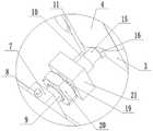
图2为图1中A处的放大示意图;Fig. 2 is the enlarged schematic diagram of place A in Fig. 1;
图3为本发明实施例的纵向剖视图;Fig. 3 is a longitudinal sectional view of an embodiment of the present invention;
图4为图3中B处的放大示意图。FIG. 4 is an enlarged schematic view of point B in FIG. 3 .
具体实施方式Detailed ways
下面通过具体实施方式进一步详细说明:The following is further described in detail through specific implementation methods:
说明书附图中的附图标记包括:风洞筒体1、基板2、建筑模型3、防风块4、空腔5、滑槽6、第一滑座7、插销8、横杆9、检测杆10、风力传感器11、环形槽12、第二滑座13、风机14、支杆15、压力传感器16、弹簧17、连接块18、夹紧板19、定位螺母20、移动端21。The reference signs in the drawings of the description include:
实施例Example
如图1、图2、图3与图4所示:As shown in Figure 1, Figure 2, Figure 3 and Figure 4:
基于生物仿生的结构气动优化装置,包括风洞筒体1,所述风洞筒体1内部固定有水平设置的基板2,基板2中心处开设有空腔5,空腔5中心处可拆卸有建筑模型3,建筑模型3周侧均螺栓连接有防风块4;所述防风块4的外表面均为流线型,防风块4的底部与基板2齐平;所述凹腔内开设有四条平行于建筑模型3侧壁的凹槽,凹槽内均滑动有第一滑座7,第一滑座7上设置有风压测试装置,第一滑座7上设置有插销8,滑槽6内设置有等间距分布的若干销孔;所述风压测试装置包括横杆9与检测杆10,横杆9水平固定在第一滑座7上;所述检测杆10竖向设置,检测杆10的底端滑动连接在横杆9上,检测杆10的底端上还设置有锁紧装置;所述检测杆10贴合在防风块4外表面,检测杆10上设置有若干均匀分布的风力传感器11;所述基板2上还设置有风力发生装置。The structural aerodynamic optimization device based on bionics includes a
取下插销8后,滑动第一滑座7,从而调节对应风压测试装置的位置,使风压测试装置正对防风块4上所需测试的位置,插入插销8将第一滑座7固定住;调节检测杆10,检测杆10在横杆9上滑动,使检测杆10能够贴合防风块4的表面,再利用锁紧装置进行锁紧。再启动风力发生装置,使风朝向建筑模型3吹过,利用检测杆10表面的风力传感器11进行测量。测量结束后,关闭风力发生装置,再次取下插销8后,滑动第一滑座7,使风压测试装置正对下一个测试位置,重复上述过程,直至测试结束;再将防风块4拆卸下来,更换其他尺寸的防风块4,再次进行测试。After removing the
通过调节第一滑座7的滑动,带动风压测试装置滑动,再通过调节检测杆10在横杆9上滑动,使检测杆10完全贴合防风块4的表面移动,让检测杆10上的风力传感器11更加接近防风块4的表面,所测得风压数据更加的精准,能够更加直观的测量流线型仿生结构表面的压力状况;此外,检测杆10上的风力传感器11呈和等间距分布,可同时测量同一竖直方向上防风块4表面不同高度的风压状况,为实验提供更加精确的数据,从而更加全面了解仿生结构气动分布情况,便于对生物仿生结构进行气动优化。By adjusting the sliding of the first sliding
可选地,风力发生装置包括风机14与第二滑座13,所述基板2上开设有若干环形槽12,环形槽12均与建筑模型3同圆心,且环形槽12呈等间距分布,环形槽12内滑动连接有第二滑座13,第二滑座13上可拆卸连接有风机14,风机14朝向建筑模型3。Optionally, the wind generating device includes a
将风机14通过螺栓连接安装在对应的第二滑座13上,起到调节风机14与建筑模型3之间距离的作用,从而达到对风力的控制;然后推动第二滑座13,从而调节风机14与建筑模型3之间的角度,达到调节风向,使风机14所产生风的强度与角度处于实验测试所需状态。Install the
通过若干的同圆心的环形槽12,环形槽12内均设置有第二滑座13,仅需将风机14安装对应的第二滑座13上,即可完成对风机14距离的调整,从而达到对风力的控制;同时,滑动第二滑座13,能够调节风机14与建筑模型3之间的角度,形成对风力大小与角度的调节,从而更加精确的完成对防风块4表面各种情况下的风压状况,从而更加全面了解仿生结构气动分布情况,便于对生物仿生结构进行气动优化。Through a number of concentric
此外,风机14运作时,风机14产生的后坐力让第二滑座13抵住环形槽12,起到固定的作用,无需另外设置锁紧装置,使第二滑座13的调节更加便捷。In addition, when the
可选地,横杆9均没于凹腔中,横杆9端部上开设有连接孔,连接孔内滑动连接有支杆15,支杆15端部固定有压力传感器16,压力传感器16贴合在建筑模型3侧面上,且支杆15与横杆9之间固定有弹簧17;所述检测杆10包括移动端21和连接杆,移动端21滑动套设在横杆9上,连接杆为L形,所述风力传感器11均固定在连接杆上。Optionally, the
在测试过程中,横杆9端部滑动连接的支杆15通过压力传感器16与建筑模型3底部贴合,能够检测到在风力状态下,建筑模型3底部的受力变化,以此来模拟建筑结构在土壤等结构中的底部受力情况,为分析仿生结构表面气动状况提供更加全面、更加贴合实际情况的数据。During the test, the
可选地,建筑模型3侧壁上开设有若干竖向的连接槽,连接槽的横截面为T形,且连接槽底部封闭;所述防风块4上固定有与连接槽配合的连接块18,连接块18长度与连接槽长度相等。Optionally, several vertical connection grooves are provided on the side wall of the
通过设置连接块18与连接槽之间的配合,使防风块4与建筑模型3之间处于可拆卸的状态,便于更换不同尺寸的防风块4。By setting the cooperation between the connecting
可选地,锁紧装置包括固定在检测杆10底端的若干夹紧板19,夹紧板19绕横杆9圆形阵列分布,且夹紧板19的自由端均朝向滑座;夹紧板19为弹性的曲形板,夹紧板19内壁上固定有橡胶层与横杆9接触,夹紧板19的厚度逐渐递增,夹紧板19上螺纹连接定位螺母20。Optionally, the locking device includes
在检测杆10停止运动后,旋转定位螺母20使定位螺母20朝向移动端21运动,由于夹紧板19的厚度逐渐递增,定位螺母20朝向移动端21运动的过程中,定位螺母20不断挤压夹紧板19,使夹紧板19与横杆9之间的摩擦力越来越大,当定位螺母20运动至一定位置时,夹紧板19与横杆9之间的摩擦力增大到一定的程度,夹紧板19固定在横杆9上,从而将移动端21固定住,本身夹紧板19上固定有橡胶层与横杆9接触,增大夹紧板19与横杆9之间的摩擦,增强夹紧板19与横杆9之间的稳定性;而需要移动检测杆10时,仅需反向旋转定位螺母20即可,整个检测杆10的固定方式简单快捷,能够有效的提高加工效率。After the
可选地,检测杆10贴合防风块4的表面光滑。Optionally, the surface of the
以上所述的仅是本发明的实施例,方案中公知的具体结构及特性等常识在此未作过多描述。应当指出,对于本领域的技术人员来说,在不脱离本发明结构的前提下,还可以作出若干变形和改进,这些也应该视为本发明的保护范围,这些都不会影响本发明实施的效果和本发明的实用性。What is described above is only an embodiment of the present invention, and common knowledge such as specific structures and characteristics known in the scheme are not described here too much. It should be pointed out that for those skilled in the art, under the premise of not departing from the structure of the present invention, several modifications and improvements can also be made, and these should also be regarded as the protection scope of the present invention, and these will not affect the implementation of the present invention. Effects and practicability of the present invention.
Claims (5)
Translated fromChinesePriority Applications (1)
| Application Number | Priority Date | Filing Date | Title |
|---|---|---|---|
| CN202011449408.9ACN112541217B (en) | 2020-12-11 | 2020-12-11 | Pneumatic optimization device of structure based on bionics |
Applications Claiming Priority (1)
| Application Number | Priority Date | Filing Date | Title |
|---|---|---|---|
| CN202011449408.9ACN112541217B (en) | 2020-12-11 | 2020-12-11 | Pneumatic optimization device of structure based on bionics |
Publications (2)
| Publication Number | Publication Date |
|---|---|
| CN112541217A CN112541217A (en) | 2021-03-23 |
| CN112541217Btrue CN112541217B (en) | 2022-11-08 |
Family
ID=75020072
Family Applications (1)
| Application Number | Title | Priority Date | Filing Date |
|---|---|---|---|
| CN202011449408.9AExpired - Fee RelatedCN112541217B (en) | 2020-12-11 | 2020-12-11 | Pneumatic optimization device of structure based on bionics |
Country Status (1)
| Country | Link |
|---|---|
| CN (1) | CN112541217B (en) |
Citations (10)
| Publication number | Priority date | Publication date | Assignee | Title |
|---|---|---|---|---|
| CN101872380A (en)* | 2010-07-09 | 2010-10-27 | 上海理工大学 | A Method for Reducing Energy Consumption Loss of Regional Buildings |
| CN104697292A (en)* | 2014-05-25 | 2015-06-10 | 刘晓 | Super air purification application system |
| CN106149943A (en)* | 2015-04-27 | 2016-11-23 | 吴志勇 | A kind of stacked slide switching apparatus for building with Wind-proof mechanism |
| CN109307580A (en)* | 2018-12-05 | 2019-02-05 | 重庆大学 | A Synchronous Aeroelasticity-Panometric Wind Tunnel Test Device Considering Aerodynamic Interference Effects |
| CN209955573U (en)* | 2019-03-12 | 2020-01-17 | 黄力树 | Pneumatic type book back milling flutes mechanism |
| CN111458102A (en)* | 2019-10-21 | 2020-07-28 | 中国建筑股份有限公司 | Building model indoor natural ventilation testing arrangement |
| WO2020159034A1 (en)* | 2019-01-30 | 2020-08-06 | 서울대학교 산학협력단 | Artificial intelligence-based method and system for automatic determination of design wind speed |
| CN111639428A (en)* | 2020-05-28 | 2020-09-08 | 上海电气风电集团股份有限公司 | Dynamic simulation method, device and medium for wind driven generator with flap |
| CN111709175A (en)* | 2020-06-29 | 2020-09-25 | 广西路桥工程集团有限公司 | Large-span arch bridge arch ring linear control method and optimization calculation model |
| CN211736073U (en)* | 2020-04-07 | 2020-10-23 | 海南大学 | A prefabricated pneumatic control structure for building roof flow field control and optimization |
Family Cites Families (4)
| Publication number | Priority date | Publication date | Assignee | Title |
|---|---|---|---|---|
| US20050115248A1 (en)* | 2003-10-29 | 2005-06-02 | Koehler Gregory J. | Liquefied natural gas structure |
| US8436489B2 (en)* | 2009-06-29 | 2013-05-07 | Lightsail Energy, Inc. | Compressed air energy storage system utilizing two-phase flow to facilitate heat exchange |
| CN109923264B (en)* | 2016-09-14 | 2023-01-06 | 爱马特伦系统有限责任公司 | Method for reinforcing cement buildings by high-speed extrusion printing and apparatus for using the method |
| US11156201B2 (en)* | 2018-05-17 | 2021-10-26 | Lone Gull Holdings, Ltd. | Inertial pneumatic wave energy device |
- 2020
- 2020-12-11CNCN202011449408.9Apatent/CN112541217B/ennot_activeExpired - Fee Related
Patent Citations (10)
| Publication number | Priority date | Publication date | Assignee | Title |
|---|---|---|---|---|
| CN101872380A (en)* | 2010-07-09 | 2010-10-27 | 上海理工大学 | A Method for Reducing Energy Consumption Loss of Regional Buildings |
| CN104697292A (en)* | 2014-05-25 | 2015-06-10 | 刘晓 | Super air purification application system |
| CN106149943A (en)* | 2015-04-27 | 2016-11-23 | 吴志勇 | A kind of stacked slide switching apparatus for building with Wind-proof mechanism |
| CN109307580A (en)* | 2018-12-05 | 2019-02-05 | 重庆大学 | A Synchronous Aeroelasticity-Panometric Wind Tunnel Test Device Considering Aerodynamic Interference Effects |
| WO2020159034A1 (en)* | 2019-01-30 | 2020-08-06 | 서울대학교 산학협력단 | Artificial intelligence-based method and system for automatic determination of design wind speed |
| CN209955573U (en)* | 2019-03-12 | 2020-01-17 | 黄力树 | Pneumatic type book back milling flutes mechanism |
| CN111458102A (en)* | 2019-10-21 | 2020-07-28 | 中国建筑股份有限公司 | Building model indoor natural ventilation testing arrangement |
| CN211736073U (en)* | 2020-04-07 | 2020-10-23 | 海南大学 | A prefabricated pneumatic control structure for building roof flow field control and optimization |
| CN111639428A (en)* | 2020-05-28 | 2020-09-08 | 上海电气风电集团股份有限公司 | Dynamic simulation method, device and medium for wind driven generator with flap |
| CN111709175A (en)* | 2020-06-29 | 2020-09-25 | 广西路桥工程集团有限公司 | Large-span arch bridge arch ring linear control method and optimization calculation model |
Non-Patent Citations (1)
| Title |
|---|
| "开洞建筑风致内压的过冲响应及干扰效应研究";李尚启;《中国优秀硕士学位论文全文数据库工程科技Ⅱ辑》;20170215;第45-50页* |
Also Published As
| Publication number | Publication date |
|---|---|
| CN112541217A (en) | 2021-03-23 |
Similar Documents
| Publication | Publication Date | Title |
|---|---|---|
| CN105136507B (en) | The experimental provision of a kind of lab simulation tunnel excavation and method | |
| WO2020114149A1 (en) | Sample making die for rock body structural surface shear test | |
| CN109973103B (en) | An angle-adjustable shield simulation test device | |
| CN206920100U (en) | A kind of rectangle round steel pipe transition mast attachment structure bidirectional load test device | |
| CN103968745A (en) | Structural plane roughness coefficient measuring device and using method thereof | |
| CN103063461B (en) | Rock burst model test apparatus | |
| CN110686980B (en) | Tunnel excavation analogue means under inhomogeneous side direction load | |
| CN112541217B (en) | Pneumatic optimization device of structure based on bionics | |
| CN204944860U (en) | A kind of experimental provision of lab simulation tunnel excavation | |
| Rui et al. | Mobilization mechanism and calculation method of embedded chain axial resistance in sand | |
| CN207700013U (en) | A kind of asphalt Reflective Cracking Resistance detection device | |
| CN108198505B (en) | Shield type TBM tunnel bean gravel construction simulation device | |
| CN104614244A (en) | High-stress roadway stability similarity simulation test device and method | |
| CN104634661B (en) | Three-dimensional model apparatus for testing rock masses in deep tunnel and using method of testing apparatus | |
| CN102980750A (en) | Aircraft wing long purlin assembling process and automatic simulation experiment set of clamp force | |
| CN211784804U (en) | Asphalt pavement structural strength detection device | |
| CN108267360A (en) | Microcomputer controls true triaxial frozen soil experiment machine | |
| CN206515124U (en) | A kind of experiment mould for being used to make proportioning test specimen | |
| CN204495322U (en) | Asphalt creep test radial strain real-time test device | |
| CN207300685U (en) | A kind of new earthen ruins building sampling die | |
| CN207662634U (en) | Simulative automobile test counter weight device | |
| LU502101B1 (en) | Test device and test method for simulating cavity behind shield tunnel lining | |
| CN212300880U (en) | Fixing device for indoor model test displacement gauge with hinge | |
| CN210071502U (en) | A normal fault simulation test device with adjustable angle and crack initiation position | |
| CN115050256A (en) | Landslide model device capable of changing curvature and gradient |
Legal Events
| Date | Code | Title | Description |
|---|---|---|---|
| PB01 | Publication | ||
| PB01 | Publication | ||
| SE01 | Entry into force of request for substantive examination | ||
| SE01 | Entry into force of request for substantive examination | ||
| GR01 | Patent grant | ||
| GR01 | Patent grant | ||
| CF01 | Termination of patent right due to non-payment of annual fee | ||
| CF01 | Termination of patent right due to non-payment of annual fee | Granted publication date:20221108 |