CN112523698B - Foldable top drive guide rail - Google Patents
Foldable top drive guide railDownload PDFInfo
- Publication number
- CN112523698B CN112523698BCN202110016496.1ACN202110016496ACN112523698BCN 112523698 BCN112523698 BCN 112523698BCN 202110016496 ACN202110016496 ACN 202110016496ACN 112523698 BCN112523698 BCN 112523698B
- Authority
- CN
- China
- Prior art keywords
- guide rail
- plate
- rail
- sliding
- upper guide
- Prior art date
- Legal status (The legal status is an assumption and is not a legal conclusion. Google has not performed a legal analysis and makes no representation as to the accuracy of the status listed.)
- Withdrawn - After Issue
Links
- 238000005192partitionMethods0.000claimsdescription24
- 230000005540biological transmissionEffects0.000claimsdescription4
- 238000009434installationMethods0.000abstractdescription9
- 238000005553drillingMethods0.000abstractdescription7
- 230000009286beneficial effectEffects0.000abstractdescription2
- 238000010276constructionMethods0.000abstract2
- 210000001503jointAnatomy0.000abstract1
- 239000003208petroleumSubstances0.000abstract1
- 238000010586diagramMethods0.000description9
- 238000005457optimizationMethods0.000description9
- 238000000034methodMethods0.000description3
- 230000005484gravityEffects0.000description2
- 230000003014reinforcing effectEffects0.000description2
- 238000004891communicationMethods0.000description1
- 230000000694effectsEffects0.000description1
- 238000005516engineering processMethods0.000description1
- 238000011900installation processMethods0.000description1
- 239000011159matrix materialSubstances0.000description1
- 238000003032molecular dockingMethods0.000description1
- 238000007665saggingMethods0.000description1
Images


Classifications
- E—FIXED CONSTRUCTIONS
- E21—EARTH OR ROCK DRILLING; MINING
- E21B—EARTH OR ROCK DRILLING; OBTAINING OIL, GAS, WATER, SOLUBLE OR MELTABLE MATERIALS OR A SLURRY OF MINERALS FROM WELLS
- E21B15/00—Supports for the drilling machine, e.g. derricks or masts
- E21B15/003—Supports for the drilling machine, e.g. derricks or masts adapted to be moved on their substructure, e.g. with skidding means; adapted to drill a plurality of wells
Landscapes
- Engineering & Computer Science (AREA)
- Life Sciences & Earth Sciences (AREA)
- Geology (AREA)
- Mining & Mineral Resources (AREA)
- Mechanical Engineering (AREA)
- Physics & Mathematics (AREA)
- Environmental & Geological Engineering (AREA)
- Fluid Mechanics (AREA)
- General Life Sciences & Earth Sciences (AREA)
- Geochemistry & Mineralogy (AREA)
- Power-Operated Mechanisms For Wings (AREA)
- Curtains And Furnishings For Windows Or Doors (AREA)
Abstract
Description
Translated fromChinese技术领域technical field
本发明涉及石油钻井顶驱设备领域,具体地说是一种折叠式顶驱导轨。The invention relates to the field of oil drilling top drive equipment, in particular to a foldable top drive guide rail.
背景技术Background technique
随着油气钻井技术的开发,传统钻机配备顶驱的需求越来越迫切。导轨作为顶驱装备中不可或缺的一个组成部分,不仅能是顶驱沿着导轨上下滑动,而且能够承受并传递顶驱驱动钻杆在旋转钻进、上扣、卸扣时的反扭矩。目前,国内外顶驱钻井装备中,导轨安装主要靠工人高空穿销轴连接,需要吊着导轨悬在30m-40m高空,将两端导轨的销轴孔对齐,将销轴打进销轴孔内,由于作业空间和环境限制,高空穿销轴难度大,耗时长,工作人员劳动强度大,发生高空坠落的风险高。With the development of oil and gas drilling technology, the need for traditional drilling rigs to be equipped with top drive is more and more urgent. As an indispensable part of the top drive equipment, the guide rail can not only allow the top drive to slide up and down along the guide rail, but also bear and transmit the reaction torque of the top drive driving drill pipe during rotary drilling, make-up and breakout. At present, in the top drive drilling equipment at home and abroad, the installation of the guide rail is mainly connected by the workers through the pin shaft at high altitude. Due to the limitation of working space and environment, it is difficult and time-consuming to thread the pin shaft at high altitudes, the labor intensity of the staff is high, and the risk of falling from high altitudes is high.
发明内容SUMMARY OF THE INVENTION
本发明提供了一种折叠式顶驱导轨,其特点是安装时不需要对接,不仅装卸省时省力、装卸效率高、装卸成本低且操作简单,同时免去高空作业及伴随高空作业带来的风险。The invention provides a foldable top drive guide rail, which is characterized in that no docking is required during installation, which not only saves time and labor for loading and unloading, has high loading and unloading efficiency, low loading and unloading costs, and is simple to operate, but also avoids high-altitude operations and the associated problems caused by high-altitude operations. risk.
为实现上述目的,本发明提供如下技术方案:一种折叠式顶驱导轨,包括上导轨和下导轨;所述上导轨和下导轨之间设有连接导轨;所述上导轨、连接导轨和下导轨的两侧设有导轨。In order to achieve the above-mentioned purpose, the present invention provides the following technical solutions: a foldable top drive guide rail, comprising an upper guide rail and a lower guide rail; a connecting guide rail is provided between the upper guide rail and the lower guide rail; the upper guide rail, the connecting guide rail and the lower guide rail are provided. There are guide rails on both sides of the guide rail.
所述上导轨和连接导轨之间与连接导轨和下导轨之间均设有连接件;所述连接件的两端均设有销轴;所述上导轨和连接导轨通过两者之间连接件上的销轴相铰接;所述连接导轨和下导轨通过两者之间连接件上的销轴相铰接。A connecting piece is arranged between the upper guide rail and the connecting guide rail and between the connecting guide rail and the lower guide rail; both ends of the connecting piece are provided with pins; the upper guide rail and the connecting guide rail pass through the connecting piece between the two. The upper pins are hinged; the connecting guide rail and the lower guide rail are hinged through the pins on the connecting piece between them.
所述上导轨、连接导轨和下导轨之间设有拉绳;所述拉绳的一端通过固定环固定于上导轨上,拉绳的另一端设有拉环;所述连接件上设有开槽;所述拉绳贯穿于连接件上的开槽中。A pulling rope is arranged between the upper guide rail, the connecting guide rail and the lower guide rail; one end of the pulling rope is fixed on the upper guide rail through a fixing ring, and the other end of the pulling rope is provided with a pulling ring; The slot; the pull cord runs through the slot on the connector.
所述下导轨的下方设有下连接板;所述下连接板的下端设有固定卡梁;所述固定卡梁固定在井架横梁上;所述下连接板内设有滑移板;所述滑移板为内中空结构并设有丝杆升降机;所述滑移板的下方设有张紧板;所述丝杆升降机下端的调节丝杆与张紧板螺纹相接,丝杆升降机的侧端设有转盘;所述转盘与丝杆升降机内的升降调节丝杆相连接,通过旋转转盘带动升降调节丝杆旋转,使得升降调节丝杆与调节丝杆实现涡轮传动;所述滑移板的上方设有钩挂组件;所述钩挂组件与拉环相连接。A lower connecting plate is arranged below the lower guide rail; a fixed clamping beam is arranged at the lower end of the lower connecting plate; the fixed clamping beam is fixed on the derrick beam; a sliding plate is arranged in the lower connecting plate; The sliding plate has an inner hollow structure and is provided with a screw lift; a tension plate is arranged below the sliding plate; the adjusting screw at the lower end of the screw lift is threadedly connected with the tension plate, and the side of the screw lift is The end is provided with a turntable; the turntable is connected with the lift adjustment screw in the screw elevator, and the lift adjustment screw is driven to rotate by rotating the turntable, so that the lift adjustment screw and the adjustment screw realize turbine transmission; the sliding plate The upper part is provided with a hooking component; the hooking component is connected with the pull ring.
所述上导轨的顶部设有上连接板;所述上导轨的导轨上安装有滑移轨车,且上导轨的导轨上设有限位凸板;所述滑移轨车上设有钩挂管。采用折叠方式和重力自动打开,提高了安装时的快捷性和方便性,拉绳和丝杆升降机的配合,确保了整体的刚性强度,满足设备在运行时的正常使用。The top of the upper guide rail is provided with an upper connecting plate; the guide rail of the upper guide rail is provided with a sliding rail car, and the guide rail of the upper guide rail is provided with a limit convex plate; the sliding rail car is provided with a hook tube . It adopts the folding method and gravity to automatically open, which improves the speed and convenience of installation. The cooperation of the pull rope and the screw lift ensures the overall rigidity and strength, and meets the normal use of the equipment during operation.
作为优化,所述上导轨、连接导轨和下导轨均为内中空结构,且上导轨、连接导轨和下导轨的内部均设有隔板;所述固定环固定于上导轨内的隔板上;所述拉绳依次经过上导轨、连接导轨、下导轨和下连接板的内部。隔板的设计进一步提高了导轨的强度,并提供了分层空间,起到一定的导向作用和应力支撑作用。As an optimization, the upper guide rail, the connecting guide rail and the lower guide rail are all hollow structures, and the upper guide rail, the connecting guide rail and the lower guide rail are all provided with partition plates; the fixing ring is fixed on the partition plate in the upper guide rail; The pulling rope passes through the upper guide rail, the connecting guide rail, the lower guide rail and the interior of the lower connecting plate in sequence. The design of the clapboard further improves the strength of the guide rail, and provides a layered space, which plays a certain guiding role and stress support role.
作为优化,所述上导轨下端、连接导轨两端和下导轨两端,三者的隔板上均设有导线槽;所述拉绳依次通过上导轨下端的导线槽、上导轨和连接导轨之间连接件的开槽、连接导轨两端的导线槽、连接导轨和下导轨之间连接件的开槽和下导轨的两端导线槽。导线槽的结构设计,确保了拉绳不会出现搅绳的现象。As an optimization, the lower end of the upper guide rail, the two ends of the connecting guide rail and the two ends of the lower guide rail are provided with wire grooves on the partitions of the three; The slot of the connecting piece, the wire ducts at both ends of the connecting guide rail, the slot of the connecting piece between the connecting guide rail and the lower guide rail, and the wire ducts at both ends of the lower guide rail. The structural design of the wire groove ensures that the rope will not be stirred.
作为优化,所述连接导轨设有多个且长度大小相一致。可以根据具体实际情况,对长度进行调整。As an optimization, a plurality of the connecting guide rails are provided with the same length and size. The length can be adjusted according to the actual situation.
作为优化,所述连接导轨内隔板的上端均设有导线口;所述拉绳从上向下依次贯穿于连接导轨内隔板的导线口中,并呈折线形结构。As an optimization, the upper ends of the inner partitions of the connecting guide rails are provided with wire openings; the pulling ropes are sequentially passed through the wire openings of the inner partitions of the connecting guide rails from top to bottom, and have a fold-line structure.
作为优化,所述连接导轨内隔板的下端均设有导线口;所述拉绳从上向下依次贯穿于连接导轨内隔板的导线口中,并呈折线形结构。折线形结构布局,提高拉绳的刚性强度。As an optimization, the lower ends of the inner partitions of the connecting guide rails are all provided with wire openings; the pulling ropes run through the wire openings of the inner partitions of the connecting guide rails in sequence from top to bottom, and have a folded line structure. The broken-line structure layout improves the rigidity and strength of the pull rope.
作为优化,所述上导轨上固定环的位置处设有开窗;所述钩挂组件处的下连接板上设有吊孔耳板天窗;所述转盘处的下连接板上设有转盘天窗。各种天窗的结构设计,便于实际操作中的观察和操作。As an optimization, a window is provided at the position of the fixing ring on the upper guide rail; a lifting hole lug skylight is provided on the lower connecting plate at the hooking component; a turntable skylight is provided on the lower connecting plate at the turntable . The structural design of various skylights is convenient for observation and operation in actual operation.
作为优化,所述下导轨内的拉绳上设有配重件。配重件保证了导轨在打开后,拉绳的自动下垂。As an optimization, a counterweight is provided on the pull rope in the lower guide rail. The counterweight ensures the automatic sagging of the pull rope after the guide rail is opened.
作为优化,所述滑移板的两侧设有滑移挡板;所述滑移板卡嵌于滑移挡板中;所述滑移板上设有滑移卡槽;所述滑移挡板上设有限位挡板;所述限位挡板与滑移卡槽卡嵌滑动相接。保证滑移板在运动时的稳定性。As an optimization, there are sliding baffles on both sides of the sliding plate; the sliding plate is embedded in the sliding baffle; the sliding plate is provided with a sliding slot; the sliding baffle A limit baffle plate is provided on the board; the limit baffle plate is snap-fitted and slidably connected with the sliding card slot. Ensure the stability of the sliding board during movement.
作为优化,所述钩挂组件包括连接销轴;所述连接销轴为内中空结构,其上下端均螺纹连接有旋转销轴;所述连接销轴上端的旋转销轴外连接有吊孔耳板,连接销轴下端的旋转销轴与滑移板的上方相铰接。可以起到微调的效果,确保设备的正常操作和使用。As an optimization, the hooking assembly includes a connecting pin; the connecting pin is an inner hollow structure, and the upper and lower ends of the connecting pin are threadedly connected with a rotating pin; the rotating pin on the upper end of the connecting pin is externally connected with a lifting hole lug The rotating pin at the lower end of the connecting pin is hinged with the upper part of the sliding plate. It can play a fine-tuning effect to ensure the normal operation and use of the equipment.
与现有技术相比,本发明的有益效果如下:该装置只需少数工人和设备就可完成安装和拆卸工作,大大降低劳动强度,极大减少高空作业,提高安装和拆卸效率,安全性高。通过井架顶端的大钩拉动钩挂管带动整个折叠铰接的上导轨、连接导轨和下导轨通过重力自动打开,并将上导轨上方的上连接板和下导轨的下方的下连接板分别固定在井架横梁上,再通过丝杆升降机绷紧连接在其内部的拉绳,提高整个导轨的稳定性。拉绳采用折线形结构穿插布局,保证了导轨的刚性强度。Compared with the prior art, the beneficial effects of the present invention are as follows: the device only needs a few workers and equipment to complete the installation and disassembly, greatly reduces labor intensity, greatly reduces high-altitude operations, improves installation and disassembly efficiency, and has high safety. . The hook at the top of the derrick pulls the hook tube to drive the entire folding hinged upper guide rail, connecting guide rail and lower guide rail to open automatically by gravity, and fix the upper connecting plate above the upper guide rail and the lower connecting plate below the lower guide rail on the derrick respectively. On the beam, the pull rope connected inside it is tightened through the screw lift to improve the stability of the entire guide rail. The pull rope adopts the interspersed layout of the broken line structure, which ensures the rigidity of the guide rail.
附图说明Description of drawings
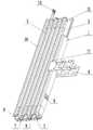
图1为本发明整体结构示意图。FIG. 1 is a schematic diagram of the overall structure of the present invention.
图2为本发明上导轨、连接导轨和下导轨,折叠状态时的立体结构示意图。FIG. 2 is a schematic three-dimensional structure diagram of the upper guide rail, the connecting guide rail and the lower guide rail according to the present invention in a folded state.
图3为本发明上导轨、连接导轨和下导轨的内部结构示意图。3 is a schematic diagram of the internal structure of the upper guide rail, the connecting guide rail and the lower guide rail of the present invention.
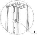
图4为本发明下连接板的立体结构示意图。FIG. 4 is a schematic three-dimensional structure diagram of the lower connecting plate of the present invention.
图5为本发明丝杆升降机的结构示意图。FIG. 5 is a schematic structural diagram of the screw elevator of the present invention.
图6为本发明滑移板的连接结构示意图。FIG. 6 is a schematic diagram of the connection structure of the sliding plate of the present invention.
图7为本发明滑移轨车的立体结构示意图。FIG. 7 is a schematic three-dimensional structure diagram of a sliding rail car according to the present invention.
图8为本发明滑移轨车的内部结构示意图。FIG. 8 is a schematic diagram of the internal structure of the sliding rail car of the present invention.
其中,上导轨1、连接导轨2、下导轨3、滑移轨车4、连接件5、销轴6、开槽7、拉绳8、固定环9、拉环10、隔板11、导线口12、导线槽13、配重件14、上连接板15、导轨16、限位凸板17、下连接板18、固定卡梁19、滑移板20、丝杆升降机21、转盘22、调节丝杆23、滑移卡槽24、限位挡板25、连接销轴26、旋转销轴27、吊孔耳板28、张紧板29、滑移挡板30、吊孔耳板天窗31、固定卡梁下夹板32、滑移限位板33、滑移支架41、轨车滑槽42、轨车滑轮43、轨车导板44、加强板45、钩挂管46、观察天窗47。Among them, the
具体实施方式Detailed ways
下面将结合本发明实施例中的附图,对本发明实施例中的技术方案进行清楚、完整地描述,显然,所描述的实施例仅仅是本发明一部分实施例,而不是全部的实施例。基于本发明中的实施例,本领域普通技术人员在没有做出创造性劳动前提下所获得的所有其他实施例,都属于本发明保护的范围。The technical solutions in the embodiments of the present invention will be clearly and completely described below with reference to the accompanying drawings in the embodiments of the present invention. Obviously, the described embodiments are only a part of the embodiments of the present invention, but not all of the embodiments. Based on the embodiments of the present invention, all other embodiments obtained by those of ordinary skill in the art without creative efforts shall fall within the protection scope of the present invention.
在本发明的描述中,需要说明的是,术语“上”、“下”、“内”、“外”“前端”、“后端”、“两端”、“一端”、“另一端”等指示的方位或位置关系为基于附图所示的方位或位置关系,仅是为了便于描述本发明和简化描述,而不是指示或暗示所指的装置或元件必须具有特定的方位、以特定的方位构造和操作,因此不能理解为对本发明的限制。此外,术语“第一”、“第二”仅用于描述目的,而不能理解为指示或暗示相对重要性。In the description of the present invention, it should be noted that the terms "upper", "lower", "inner", "outer", "front end", "rear end", "two ends", "one end" and "the other end" The orientation or positional relationship indicated by etc. is based on the orientation or positional relationship shown in the accompanying drawings, and is only for the convenience of describing the present invention and simplifying the description, rather than indicating or implying that the indicated device or element must have a specific orientation, with a specific orientation. The orientation configuration and operation are therefore not to be construed as limitations of the present invention. Furthermore, the terms "first" and "second" are used for descriptive purposes only and should not be construed to indicate or imply relative importance.
在本发明的描述中,需要说明的是,除非另有明确的规定和限定,术语“安装”、“设置有”、“连接”等,应做广义理解,例如“连接”,可以是固定连接,也可以是可拆卸连接,或一体地连接;可以是机械连接,也可以是电连接;可以是直接相连,也可以通过中间媒介间接相连,可以是两个元件内部的连通。对于本领域的普通技术人员而言,可以具体情况理解上述术语在本发明中的具体含义。In the description of the present invention, it should be noted that, unless otherwise expressly specified and limited, the terms "installed", "provided with", "connected", etc. should be understood in a broad sense, for example, "connected" may be a fixed connection It can also be a detachable connection or an integral connection; it can be a mechanical connection or an electrical connection; it can be a direct connection, or an indirect connection through an intermediate medium, or the internal communication between the two components. For those of ordinary skill in the art, the specific meanings of the above terms in the present invention can be understood in specific situations.
一种折叠式顶驱导轨,包括上导轨1和下导轨3;所述上导轨1和下导轨3之间设有连接导轨2;所述上导轨1、连接导轨2和下导轨3的两侧设有导轨16。A foldable top drive guide rail includes an
所述上导轨1和连接导轨2之间与连接导轨2和下导轨3之间均设有连接件5;所述连接件5的两端均设有销轴6;所述上导轨1和连接导轨2通过两者之间连接件5上的销轴6相铰接;所述连接导轨2和下导轨3通过两者之间连接件5上的销轴6相铰接。A connecting
所述上导轨1、连接导轨2和下导轨3之间设有拉绳8;所述拉绳8的一端通过固定环9固定于上导轨1上,拉绳8的另一端设有拉环10;所述连接件5上设有开槽7;所述拉绳8贯穿于连接件5上的开槽7中。A
所述下导轨3的下方设有下连接板18;所述下连接板18的下端设有固定卡梁19;所述固定卡梁19固定在井架横梁上;所述下连接板18内设有滑移板20;所述滑移板20为内中空结构并设有丝杆升降机21;所述滑移板20的下方设有张紧板29;所述丝杆升降机21下端的调节丝杆23与张紧板29螺纹相接,丝杆升降机21的侧端设有转盘22;所述转盘22与丝杆升降机21内的升降调节丝杆相连接,通过旋转转盘22带动升降调节丝杆旋转,使得升降调节丝杆与调节丝杆23实现涡轮传动;所述滑移板20的上方设有钩挂组件;所述钩挂组件与拉环10相连接。A lower connecting
所述上导轨1的顶部设有上连接板15;所述上导轨1的导轨16上安装有滑移轨车4,且上导轨1的导轨16上设有限位凸板17;所述滑移轨车4上设有钩挂管。The top of the
所述上导轨1、连接导轨2和下导轨3均为内中空结构,且上导轨1、连接导轨2和下导轨3的内部均设有隔板11;所述固定环9固定于上导轨1内的隔板11上;所述拉绳8依次经过上导轨1、连接导轨2、下导轨3和下连接板18的内部。The
所述上导轨1下端、连接导轨2两端和下导轨3两端,三者的隔板11上均设有导线槽13;所述拉绳8依次通过上导轨1下端的导线槽13、上导轨1和连接导轨2之间连接件5的开槽7、连接导轨2两端的导线槽13、连接导轨2和下导轨3之间连接件5的开槽7和下导轨3的两端导线槽13。所述连接导轨2设有多个且长度大小相一致。The lower end of the
所述连接导轨2内隔板11的上端均设有导线口12;所述拉绳8从上向下依次贯穿于连接导轨2内隔板11的导线口12中,并呈折线形结构。The upper ends of the
所述连接导轨2内隔板11的下端均设有导线口12;所述拉绳8从上向下依次贯穿于连接导轨2内隔板11的导线口12中,并呈折线形结构。The lower ends of the
为了进一步的提高拉绳8的稳定性,在上导轨1、连接导轨2和下导轨3的各连接处设有导线槽13,对拉绳起到导向作用。同时通过在上导轨1、连接导轨2和下导轨3内加设隔板11提高整体的强度,同时增设导线口12的设计,当需要配备多个连接导轨2以增加整体的长度时,拉绳难免会因长度过长受到影响,此时通过在所有的连接导轨2上的内隔板11上开设导线口12,并将拉绳8从上向下依次贯穿于各个连接导轨2内隔板11的导线口12中,使拉绳8呈折线形结构,以提高拉绳8整体的稳定性。In order to further improve the stability of the
所述上导轨1上固定环9的位置处设有开窗;所述钩挂组件处的下连接板18上设有吊孔耳板天窗31;所述转盘22处的下连接板18上设有转盘天窗。A window is provided at the position of the fixing
所述下导轨3内的拉绳8上设有配重件14。A
如图5和图6所示,所述滑移板20的两侧设有滑移挡板30;所述滑移板20卡嵌于滑移挡板30中;所述滑移板20上设有滑移卡槽24;所述滑移挡板30上设有限位挡板25;所述限位挡板25与滑移卡槽24卡嵌滑动相接。As shown in FIG. 5 and FIG. 6 , two sides of the sliding
所述钩挂组件包括连接销轴26;所述连接销轴26为内中空结构,其上下端均螺纹连接有旋转销轴27;所述连接销轴26上端的旋转销轴27外连接有吊孔耳板28,连接销轴26下端的旋转销轴27与滑移板20的上方相铰接。The hook assembly includes a connecting
如图5所示,所述固定卡梁19的下方设有固定卡梁下夹板32;所述固定卡梁19和固定卡梁下夹板32之间通过连接螺栓将固定卡梁19紧固在井架横梁上。固定卡梁19和固定卡梁下夹板32的一端之间通过连接拴固定,另一端上还可设有滑槽,然后通过两者的滑槽适配不同宽度的井架横梁。As shown in FIG. 5 , the lower part of the fixed
如图6所示,所述下连接板18上设有滑移限位板33,且滑移限位板33位于滑移板20的内中空结构处。As shown in FIG. 6 , the lower connecting
其工作原理为,首先需要对其进行安装:How it works is that you first need to install it:
第一步:将设备整体吊装至钻台面上。Step 1: Hoist the equipment as a whole to the drilling floor.
第二步:如图7所示,利用井架大钩与滑移轨车4连接好,然后上升大钩,滑移轨车4带动上导轨1上升,使得上导轨1、连接导轨2和下导轨3自动打开,然后将上导轨1上方的上连接板15与井架的顶端固定连接,上连接板15上可以设有多个连接孔,可以根据高度确定合适连接孔穿入销轴进行固定(图中未画出)。Step 2: As shown in Figure 7, use the hook of the derrick to connect with the sliding
第三步:如图4所示,将下连接板18的下端固定在井架横梁上。此时拉绳8在配重块14的作用下自然垂落,将拉绳8下端的拉环10与吊孔耳板28相挂接。然后通过旋转转盘22带动升降调节丝杆旋转,使得升降调节丝杆与调节丝杆23实现涡轮传动,以此绷紧拉绳8,实现上导轨1、连接导轨2和下导轨3的绷紧,确保设备可以在导轨16上正常使用。Step 3: As shown in Figure 4, fix the lower end of the lower connecting
第四步:如图1所示,为连接安装好后的结构示意图。此时将与滑移轨车4连接好的井架大钩下放,使得滑移轨车4沿导轨16,自动下落,并将其从下连接板18处拆卸下来。Step 4: As shown in Figure 1, it is a schematic diagram of the structure after the connection is installed. At this time, the derrick hook connected with the sliding
完成上述安装全部过程。Complete all the above installation procedures.
拆卸过程与上述安装过程相反,因此不再赘述。The disassembly process is opposite to the above-mentioned installation process, so it will not be repeated.
进一步的,如图7和图8所示,所述滑移轨车4包括滑移支架41;所述滑移支架41内一端的两侧设有轨车滑槽42,滑移支架41内的另一端设有钩挂管46;所述轨车滑槽42卡嵌于折叠导轨的导轨上;所述轨车滑槽42的上下端两侧对称设有轨车滑轮43;所述轨车滑轮43外侧设有呈向外扩口状的轨车导板44。所述轨车滑轮43外包裹有橡胶层,且水平方向上轨车滑轮43之间的距离小于轨车滑槽42的内径宽度。滑移轨车4在轨车导板44的导向下进入轨车滑槽42中,为了提高滑动时的稳定性并降低滑动时的摩擦力因此加设轨车滑轮43。所述轨车滑槽42与滑移支架41之间和轨车导板44与滑移支架41之间均设有加强板45。以提高整体的连接结构强度。所述钩挂管46设有多个且呈矩阵状分布。所述钩挂管46之间设有观察天窗47。在钩挂作业时能够直观的观察钩挂情况,并跟根据需要进行选择钩挂点。所述滑移支架41上开设有若干的安装孔;所述钩挂管46的两端可拆卸的安装于滑移支架41的安装孔上。Further, as shown in FIG. 7 and FIG. 8 , the sliding
进一步的,所述拉绳8设有至少两根。根据具体情况需要设计拉绳的数量。以提高整体整体的稳定性。Further, there are at least two
对于本领域技术人员而言,显然本发明不限于上述示范性实施例的细节,而且在不背离本发明的精神或基本特征的情况下,能够以其他的具体形式实现本发明。因此,无论从哪一点来看,均应将实施例看作是示范性的,而且是非限制性的,本发明的范围由所附权利要求而不是上述说明限定,因此旨在将落在权利要求的等同要件的含义和范围内的所有变化囊括在本发明内。不应将权利要求中的任何附图标记视为限制所涉及的权利要求。It will be apparent to those skilled in the art that the present invention is not limited to the details of the above-described exemplary embodiments, but that the present invention may be embodied in other specific forms without departing from the spirit or essential characteristics of the invention. Therefore, the embodiments are to be regarded in all respects as illustrative and not restrictive, and the scope of the invention is to be defined by the appended claims rather than the foregoing description, which are therefore intended to fall within the scope of the claims. All changes within the meaning and scope of the equivalents of , are included in the present invention. Any reference signs in the claims shall not be construed as limiting the involved claim.
Claims (10)
Priority Applications (1)
| Application Number | Priority Date | Filing Date | Title |
|---|---|---|---|
| CN202110016496.1ACN112523698B (en) | 2021-01-07 | 2021-01-07 | Foldable top drive guide rail |
Applications Claiming Priority (1)
| Application Number | Priority Date | Filing Date | Title |
|---|---|---|---|
| CN202110016496.1ACN112523698B (en) | 2021-01-07 | 2021-01-07 | Foldable top drive guide rail |
Publications (2)
| Publication Number | Publication Date |
|---|---|
| CN112523698A CN112523698A (en) | 2021-03-19 |
| CN112523698Btrue CN112523698B (en) | 2022-07-01 |
Family
ID=74977230
Family Applications (1)
| Application Number | Title | Priority Date | Filing Date |
|---|---|---|---|
| CN202110016496.1AWithdrawn - After IssueCN112523698B (en) | 2021-01-07 | 2021-01-07 | Foldable top drive guide rail |
Country Status (1)
| Country | Link |
|---|---|
| CN (1) | CN112523698B (en) |
Citations (11)
| Publication number | Priority date | Publication date | Assignee | Title |
|---|---|---|---|---|
| DE10054508A1 (en)* | 2000-11-03 | 2002-05-23 | Reiner Hartmann | Miniature well drilling unit, comprising folding mast positioned on top of rotating base moving on tracks |
| CN101078334A (en)* | 2007-06-15 | 2007-11-28 | 张宝有 | Well drilling top drive guide rail plate |
| CN101963046A (en)* | 2010-09-11 | 2011-02-02 | 张宝有 | Top driving slippery insert type folding guide rail plate |
| CN201835755U (en)* | 2010-09-11 | 2011-05-18 | 张宝有 | Top drive sliding plug type folding guide rail plate |
| CA2726088A1 (en)* | 2010-12-21 | 2012-06-21 | 1570094 Alberta Ltd. | A mobile lift platform |
| CN203097735U (en)* | 2013-02-26 | 2013-07-31 | 中国石油集团长城钻探工程有限公司顶驱技术分公司 | Foldable type top-driving guide rail |
| CN103291210A (en)* | 2012-02-23 | 2013-09-11 | 陕西鑫隆石油设备有限公司 | Gate-type double-tower gear-driven drilling machine |
| CN106522832A (en)* | 2016-12-16 | 2017-03-22 | 四川宏华石油设备有限公司 | Vertically lifting drill |
| CN208749313U (en)* | 2018-03-27 | 2019-04-16 | 济南芯乐智能设备有限公司 | A kind of petroleum well workover Work robot |
| CN210598806U (en)* | 2019-09-20 | 2020-05-22 | 四川昆仑石油设备制造有限公司 | Top drive guide rail |
| CN111734326A (en)* | 2020-07-29 | 2020-10-02 | 东营市三和石油装备有限公司 | Foldable guide rail for workover pipe arranging operation |
- 2021
- 2021-01-07CNCN202110016496.1Apatent/CN112523698B/ennot_activeWithdrawn - After Issue
Patent Citations (11)
| Publication number | Priority date | Publication date | Assignee | Title |
|---|---|---|---|---|
| DE10054508A1 (en)* | 2000-11-03 | 2002-05-23 | Reiner Hartmann | Miniature well drilling unit, comprising folding mast positioned on top of rotating base moving on tracks |
| CN101078334A (en)* | 2007-06-15 | 2007-11-28 | 张宝有 | Well drilling top drive guide rail plate |
| CN101963046A (en)* | 2010-09-11 | 2011-02-02 | 张宝有 | Top driving slippery insert type folding guide rail plate |
| CN201835755U (en)* | 2010-09-11 | 2011-05-18 | 张宝有 | Top drive sliding plug type folding guide rail plate |
| CA2726088A1 (en)* | 2010-12-21 | 2012-06-21 | 1570094 Alberta Ltd. | A mobile lift platform |
| CN103291210A (en)* | 2012-02-23 | 2013-09-11 | 陕西鑫隆石油设备有限公司 | Gate-type double-tower gear-driven drilling machine |
| CN203097735U (en)* | 2013-02-26 | 2013-07-31 | 中国石油集团长城钻探工程有限公司顶驱技术分公司 | Foldable type top-driving guide rail |
| CN106522832A (en)* | 2016-12-16 | 2017-03-22 | 四川宏华石油设备有限公司 | Vertically lifting drill |
| CN208749313U (en)* | 2018-03-27 | 2019-04-16 | 济南芯乐智能设备有限公司 | A kind of petroleum well workover Work robot |
| CN210598806U (en)* | 2019-09-20 | 2020-05-22 | 四川昆仑石油设备制造有限公司 | Top drive guide rail |
| CN111734326A (en)* | 2020-07-29 | 2020-10-02 | 东营市三和石油装备有限公司 | Foldable guide rail for workover pipe arranging operation |
Also Published As
| Publication number | Publication date |
|---|---|
| CN112523698A (en) | 2021-03-19 |
Similar Documents
| Publication | Publication Date | Title |
|---|---|---|
| CN201116453Y (en) | Drilling tool sleeve transmission device | |
| CN112523698B (en) | Foldable top drive guide rail | |
| CN114933231A (en) | Row pipe bundle hoisting tool and construction method thereof | |
| CN103407921B (en) | Hoisting mechanism of crane | |
| CN202064840U (en) | Four-drill column drill derrick | |
| CN205846671U (en) | A cable tray that is easy to retract and unwind cables | |
| CN116289354A (en) | Self-propelled railway rail and sleeper collection equipment | |
| CN216272773U (en) | Pipeline lifting device for constructional engineering | |
| CN200940423Y (en) | Folding lift type rolling curtain | |
| CN214659974U (en) | Top drive guide rail folding mechanism | |
| CN218058210U (en) | A hoisting device for prefabricated I-beams in house construction | |
| CN106869743B (en) | For open-and-close mechanism above and below the wound form self-balancing in outdoor huge wall curtain system | |
| CN213571583U (en) | Cable-strand mid-span sag adjustment retractable system | |
| CN214660012U (en) | Guide rail hooking device for folding top drive guide rail | |
| CN205297356U (en) | Two pneumatic cylinders play to rise rig | |
| CN104278946B (en) | Grafting assembled water drilling rig | |
| CN2756806Y (en) | New vertically mounting and lifting drilling bit derrick | |
| CN206487461U (en) | Self-elevating drilling platform logging truck top sheave suspension | |
| CN217902558U (en) | Electric stay wire curtain mounting bracket for teaching | |
| CN115493281B (en) | Air pipe fixing structure applied to laboratory heating and ventilation equipment and mounting method thereof | |
| CN217177668U (en) | Positioning bracket for water supply and drainage engineering pipeline | |
| CN217380427U (en) | Integral lifting structure of derrick and base of land drilling machine | |
| CN214659976U (en) | Rope pulling device for folding top drive guide rail | |
| CN205370459U (en) | Derrick telescoping device | |
| CN112145089B (en) | Racking platform and method capable of effectively improving operation safety |
Legal Events
| Date | Code | Title | Description |
|---|---|---|---|
| PB01 | Publication | ||
| PB01 | Publication | ||
| SE01 | Entry into force of request for substantive examination | ||
| SE01 | Entry into force of request for substantive examination | ||
| GR01 | Patent grant | ||
| GR01 | Patent grant | ||
| AV01 | Patent right actively abandoned | Granted publication date:20220701 Effective date of abandoning:20241110 | |
| AV01 | Patent right actively abandoned | Granted publication date:20220701 Effective date of abandoning:20241110 | |
| AV01 | Patent right actively abandoned | ||
| AV01 | Patent right actively abandoned |