CN112505417B - Method for measuring resistivity of conductor material - Google Patents
Method for measuring resistivity of conductor materialDownload PDFInfo
- Publication number
- CN112505417B CN112505417BCN202011302812.3ACN202011302812ACN112505417BCN 112505417 BCN112505417 BCN 112505417BCN 202011302812 ACN202011302812 ACN 202011302812ACN 112505417 BCN112505417 BCN 112505417B
- Authority
- CN
- China
- Prior art keywords
- conductor ring
- permanent magnet
- standard
- conductor
- resistivity
- Prior art date
- Legal status (The legal status is an assumption and is not a legal conclusion. Google has not performed a legal analysis and makes no representation as to the accuracy of the status listed.)
- Active
Links
- 239000004020conductorSubstances0.000titleclaimsabstractdescription108
- 238000000034methodMethods0.000titleclaimsabstractdescription35
- 239000000463materialSubstances0.000titleclaimsabstractdescription23
- 238000005259measurementMethods0.000claimsabstractdescription27
- 238000002474experimental methodMethods0.000claimsabstractdescription24
- 230000008569processEffects0.000claimsabstractdescription19
- 238000012360testing methodMethods0.000claimsabstractdescription12
- 230000009471actionEffects0.000claimsabstractdescription4
- 230000007246mechanismEffects0.000claimsdescription4
- RYGMFSIKBFXOCR-UHFFFAOYSA-NCopperChemical compound[Cu]RYGMFSIKBFXOCR-UHFFFAOYSA-N0.000description6
- 229910052802copperInorganic materials0.000description6
- 239000010949copperSubstances0.000description6
- 238000010586diagramMethods0.000description5
- 238000000691measurement methodMethods0.000description5
- 229910052782aluminiumInorganic materials0.000description3
- XAGFODPZIPBFFR-UHFFFAOYSA-NaluminiumChemical compound[Al]XAGFODPZIPBFFR-UHFFFAOYSA-N0.000description3
- 230000005674electromagnetic inductionEffects0.000description3
- 239000000956alloySubstances0.000description1
- 238000004458analytical methodMethods0.000description1
- 238000000418atomic force spectrumMethods0.000description1
- 230000009286beneficial effectEffects0.000description1
- 238000004364calculation methodMethods0.000description1
- 238000007405data analysisMethods0.000description1
- 230000007812deficiencyEffects0.000description1
- 230000000694effectsEffects0.000description1
- 238000005516engineering processMethods0.000description1
- 230000006698inductionEffects0.000description1
- 230000003993interactionEffects0.000description1
- 229910052751metalInorganic materials0.000description1
- 239000002184metalSubstances0.000description1
- 229910001172neodymium magnetInorganic materials0.000description1
- 238000011160researchMethods0.000description1
Images


Classifications
- G—PHYSICS
- G01—MEASURING; TESTING
- G01R—MEASURING ELECTRIC VARIABLES; MEASURING MAGNETIC VARIABLES
- G01R27/00—Arrangements for measuring resistance, reactance, impedance, or electric characteristics derived therefrom
- G01R27/02—Measuring real or complex resistance, reactance, impedance, or other two-pole characteristics derived therefrom, e.g. time constant
Landscapes
- Physics & Mathematics (AREA)
- General Physics & Mathematics (AREA)
- Measurement Of Resistance Or Impedance (AREA)
Abstract
Description
Translated fromChinese技术领域technical field
本发明涉及材料电阻率测量技术,更具体的说,是涉及一种导体材料电阻率测量方法。The invention relates to a material resistivity measurement technology, in particular to a conductor material resistivity measurement method.
背景技术Background technique
在实际工作中,一些厂家和科研单位研制的新型导体材料(如新型合金材料)在应用前需要对其电性能进行分析和测量。其中,导体材料的电阻率测量是电性能分析的重要步骤之一。In actual work, some new conductor materials (such as new alloy materials) developed by some manufacturers and research institutes need to analyze and measure their electrical properties before application. Among them, the resistivity measurement of conductor materials is one of the important steps in electrical performance analysis.
现有的测量导体材料电阻率的方法大多为接触式测量,通常使用四引线法。使用这种方法测量电阻率时,在待测金属电阻率较小的情况下,由于引线和连接等原因会导致测量出现较大的误差,测得的电阻率会明显高于其实际电阻率。Most of the existing methods for measuring the resistivity of conductive materials are contact measurements, usually using the four-lead method. When using this method to measure resistivity, when the resistivity of the metal to be tested is small, there will be large errors in the measurement due to reasons such as leads and connections, and the measured resistivity will be significantly higher than its actual resistivity.
法拉第电磁感应定律阐述了当一块永磁体穿过一个适当大小的导体环时,导体环中产生的感应电流产生的磁场总是阻碍永磁体的运动,因此,永磁体在运动过程中受到一个变化的电磁力(安培力)而这一电磁力的大小与材料电阻率具有密切关系。Faraday's law of electromagnetic induction states that when a permanent magnet passes through a conductor ring of an appropriate size, the magnetic field generated by the induced current in the conductor ring always hinders the movement of the permanent magnet. Therefore, the permanent magnet is subject to a changing force during its movement Electromagnetic force (ampere force) and the magnitude of this electromagnetic force is closely related to the material resistivity.
发明内容Contents of the invention
本发明的目的是为了克服现有技术中的不足,基于法拉第电磁感应定律提出一种导体材料电阻率测量方法。The purpose of the present invention is to overcome the deficiencies in the prior art, and propose a method for measuring the resistivity of conductor materials based on Faraday's law of electromagnetic induction.
本发明的目的是通过以下技术方案实现的。The purpose of the present invention is achieved through the following technical solutions.
本发明导体材料电阻率测量方法,包括以下过程:Conductor material resistivity measuring method of the present invention comprises the following processes:
1)标准导体环实验1) Standard conductor loop experiment
将标准导体环安装在固定平台上,永磁体通过刚性非磁性直杆与测力计固定连接,并使永磁体与标准导体环沿同中心轴线设置;The standard conductor ring is installed on a fixed platform, the permanent magnet is fixedly connected to the dynamometer through a rigid non-magnetic straight rod, and the permanent magnet and the standard conductor ring are arranged along the same central axis;
控制系统控制可控驱动电机,在可控驱动电机的作用下通过机械升降机构使得测力计和永磁体以一定速度沿中心轴线从起始位置穿过标准导体环运动到终止位置,在整个运动过程中,永磁体在不同点处所受到的力由测力计实时测量并记录,实时测量结果经过计算机处理后在显示屏上显示出来;The control system controls the controllable drive motor. Under the action of the controllable drive motor, the dynamometer and the permanent magnet move at a certain speed along the central axis from the initial position through the standard conductor ring to the final position through the mechanical lifting mechanism. During the process, the force received by the permanent magnet at different points is measured and recorded in real time by the dynamometer, and the real-time measurement results are displayed on the display screen after being processed by the computer;
2)待测导体环实验2) Test conductor loop experiment
将标准导体环换成待测导体环,重复上述标准导体环实验过程,测量出不同点处永磁体所受到的力并记录,实时测量结果经过计算机处理后在显示屏上显示出来;Replace the standard conductor ring with the conductor ring to be tested, repeat the above-mentioned standard conductor ring experiment process, measure and record the force on the permanent magnet at different points, and the real-time measurement results will be displayed on the display screen after being processed by the computer;
3)计算标准导体环实验和待测导体环实验过程中永磁体受力的比值的平均值,再乘以标准导体环的电阻率,即得到待测导体环的电阻率。3) Calculate the average value of the force ratio of the permanent magnet during the standard conductor loop experiment and the conductor loop test to be tested, and multiply it by the resistivity of the standard conductor loop to obtain the resistivity of the conductor loop to be tested.
所述标准导体环和待测导体环几何尺寸相同。The geometric dimensions of the standard conductor loop and the conductor loop to be tested are the same.
所述标准导体环实验和待测导体环实验过程完全一致,在相同测量条件下,均通过自动或手动操作驱动可控驱动电机,使得永磁体从同一初始位置以一定速度穿过导体环,到达同一终止位置,并由测力计将测量值传输至计算机中。The standard conductor loop experiment and the conductor loop experiment process to be tested are completely consistent. Under the same measurement conditions, the controllable drive motor is driven by automatic or manual operation, so that the permanent magnet passes through the conductor loop at a certain speed from the same initial position to reach The same end position, and the measured value is transmitted to the computer by the dynamometer.
与现有技术相比,本发明的技术方案所带来的有益效果是:Compared with the prior art, the beneficial effects brought by the technical solution of the present invention are:
(1)本发明涉及的电阻率测量方法为非接触式测量法,这种测量方法可以有效减小测量误差。(1) The resistivity measurement method involved in the present invention is a non-contact measurement method, which can effectively reduce measurement errors.
(2)本发明操作简捷、方便,测量误差小,在测试条件无法满足电测量法时,本发明的测量方法可以作为一种替代方法。(2) The operation of the present invention is simple and convenient, and the measurement error is small. When the test conditions cannot meet the electrical measurement method, the measurement method of the present invention can be used as an alternative method.
附图说明Description of drawings
图1是本发明导体材料电阻率测量方法的测量原理示意图。Fig. 1 is a schematic diagram of the measurement principle of the method for measuring the resistivity of conductor materials in the present invention.
图2是实施例中测量系统详细示意图。Fig. 2 is a detailed schematic diagram of the measurement system in the embodiment.
图3是实施例中测量装置示意图。Fig. 3 is a schematic diagram of the measuring device in the embodiment.
图4是实施例中导体环示意图。Fig. 4 is a schematic diagram of the conductor ring in the embodiment.
图5是实施例中测量过程示意图。Fig. 5 is a schematic diagram of the measurement process in the embodiment.
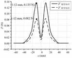
图6是对测量结果曲线图。Figure 6 is a graph of the measurement results.
具体实施方式detailed description
下面结合附图对本发明作进一步的描述。The present invention will be further described below in conjunction with the accompanying drawings.
本发明导体材料电阻率测量方法,通过标准导体材料的电阻率,对待测导体材料的电阻率进行测量,具体过程如下:Conductor material resistivity measuring method of the present invention, through the resistivity of standard conductor material, the resistivity of conductor material to be measured is measured, and concrete process is as follows:
1)标准导体环实验1) Standard conductor loop experiment
将标准导体环安装在固定平台上,永磁体通过刚性非磁性直杆与测力计固定连接,并使永磁体与标准导体环沿同中心轴线设置,如图1所示。The standard conductor ring is installed on a fixed platform, and the permanent magnet is fixedly connected to the dynamometer through a rigid non-magnetic straight rod, and the permanent magnet and the standard conductor ring are arranged along the same central axis, as shown in Figure 1.
控制系统控制可控驱动电机,在可控驱动电机的作用下通过机械升降机构使得测力计和永磁体以一定速度沿中心轴线从起始位置穿过标准导体环运动到终止位置,从而靠近、穿过并远离标准导体环,在整个运动过程中,永磁体在不同点处所受到的力由测力计实时测量并记录,实时测量结果经过计算机处理后以多种形式(如表格、图像等)在显示屏上显示出来。The control system controls the controllable driving motor. Under the action of the controllable driving motor, the dynamometer and the permanent magnet move along the central axis at a certain speed from the initial position through the standard conductor ring to the final position through the mechanical lifting mechanism, thereby approaching, Through and away from the standard conductor ring, during the whole movement process, the force on the permanent magnet at different points is measured and recorded in real time by the dynamometer, and the real-time measurement results are processed by a computer in various forms (such as tables, images, etc.) displayed on the display.
2)待测导体环实验2) Test conductor loop experiment
将标准导体环换成待测导体环,重复上述标准导体环实验过程,测量出不同点处永磁体所受到的力并记录,实时测量结果经过计算机处理后在显示屏上显示出来。Replace the standard conductor ring with the conductor ring to be tested, repeat the above-mentioned standard conductor ring experiment process, measure and record the force on the permanent magnet at different points, and the real-time measurement results will be displayed on the display after being processed by the computer.
其中,所述标准导体环和待测导体环几何尺寸相同。所述标准导体环实验和待测导体环实验过程完全一致,在相同测量条件下,均通过自动或手动操作驱动可控驱动电机,使得永磁体从同一初始位置以一定速度穿过导体环,到达同一终止位置,并由测力计将测量值传输至计算机中。Wherein, the geometric dimensions of the standard conductor loop and the conductor loop to be tested are the same. The standard conductor loop experiment and the conductor loop experiment process to be tested are completely consistent. Under the same measurement conditions, the controllable drive motor is driven by automatic or manual operation, so that the permanent magnet passes through the conductor loop at a certain speed from the same initial position to reach The same end position, and the measured value is transmitted to the computer by the dynamometer.
3)计算标准导体环实验和待测导体环实验过程中永磁体受力的比值的平均值,再乘以标准导体环的电阻率,即可得到待测导体环的电阻率。3) Calculate the average value of the force ratio of the permanent magnet during the standard conductor loop experiment and the test conductor loop experiment, and multiply it by the resistivity of the standard conductor loop to obtain the resistivity of the conductor loop to be tested.
根据安培力计算公式及法拉第电磁感应定律,当永磁体以如图1所示方式运动时,导体环内产生感应电流,感应电流产生的磁场与永磁体的磁场同极相互排斥(安培力的作用),永磁体所受合力方向为背离导体环的方向,合力大小为:According to the calculation formula of Ampere's force and Faraday's law of electromagnetic induction, when the permanent magnet moves as shown in Figure 1, an induced current is generated in the conductor ring, and the magnetic field generated by the induced current and the magnetic field of the permanent magnet repel each other with the same polarity (the effect of Ampere's force ), the direction of the resultant force on the permanent magnet is the direction away from the conductor ring, and the resultant force is:

其中,B为导体环处磁感应密度,l为导体环周长,

其中,ε为感应电动势,lR和sR分别为导体环的长度和截面积,ρ为导体材料电阻率。联立上述两式可得:Among them, ε is the induced electromotive force, lR and sR are the length and cross-sectional area of the conductor ring, respectively, and ρ is the resistivity of the conductor material. Combine the above two formulas to get:

因此,任意两种几何尺寸完全相同的导体材料在相同测量条件下,有:Therefore, any two conductor materials with identical geometric dimensions under the same measurement conditions have:

其中,F1和F2分别为导体材料1和导体材料2实验过程中永磁体所受合力,ρ1和ρ2分别为导体材料1和导体材料2的电阻率。Among them, F1 and F2 are the resultant force on the permanent magnet during the experiment of conductor material 1 and conductor material 2, respectively, and ρ1 and ρ2 are the resistivities of conductor material 1 and conductor material 2, respectively.
在两个实验过程中永磁体受力的比值的平均值,即为两材料电阻率的反比:The average value of the force ratio of the permanent magnet during the two experiments is the inverse ratio of the resistivity of the two materials:

其中,F标准和F待测分别为标准导体环实验和待测导体环实验过程中永磁体所受合力,ρ标准和ρ待测分别为标准导体环和待测导体环的电阻率。Among them, Fstandard and Fto be measured are the resultant force on the permanent magnet during the standard conductor loop experiment and the test conductor loop experiment, and ρstandard and ρto be measured are the resistivities of the standard conductor loop and the test conductor loop respectively.
下面结合附图对本发明的一个具体实施方法做进一步描述,以下实施例仅用于更清楚的描述本发明的技术方案。A specific implementation method of the present invention will be further described below in conjunction with the accompanying drawings, and the following examples are only used to more clearly describe the technical solution of the present invention.
本发明可由如图2所示的一套测量系统实施。其中测量装置由图3给出详细描述,包括:测力计③、永磁体(此处选用钕铁硼磁铁块)①、机械升降机构⑧(由可控驱动电机⑤和控制系统⑥控制)、开关组⑨、固定平台⑩。图4示意在该实施方案中使用99.95%的纯铜(电阻率为1.75×10⁻⁸Ω·m)制作的导体环作为标准导体环(测量时安装在固定平台上),铜导体环为内径30mm,外径105mm,高度10mm。磁铁的直径为20mm,高度为20mm,表面磁密0.35T。The present invention can be implemented by a measurement system as shown in FIG. 2 . The measuring device is described in detail in Figure 3, including: dynamometer ③, permanent magnet (NdFeB magnet block is selected here) ①, mechanical lifting mechanism ⑧ (controlled by controllable drive motor ⑤ and control system ⑥), Switch group ⑨, fixed platform ⑩. Figure 4 shows that in this embodiment, a conductor ring made of 99.95% pure copper (resistivity 1.75×10⁻⁸ Ω·m) is used as a standard conductor ring (installed on a fixed platform during measurement), and the copper conductor ring is the inner diameter 30mm, outer diameter 105mm, height 10mm. The diameter of the magnet is 20mm, the height is 20mm, and the surface magnetic density is 0.35T.
如图5所示,测量时先将铜导体环安装在固定平台上,利用电机驱动或手动方式使测力计连同永磁体以一定速度穿过铜导体环。通过测力计测量出永磁体在运动过程中不同点所受的外力,并将所测数据输送到计算机数据分析系统。使用几何参数与铜导体环完全相同的铝导体环作为待测导体环,重复上述过程,得到铜导体环和铝导体环与永磁体间的电磁相互作用力曲线如图6所示。计算在两个实验过程中永磁体受力的比值的平均值:As shown in Figure 5, the copper conductor ring is first installed on a fixed platform during measurement, and the dynamometer and the permanent magnet are driven through the copper conductor ring at a certain speed by motor drive or manual mode. The external force on the permanent magnet at different points during the movement is measured by the dynamometer, and the measured data is sent to the computer data analysis system. Use the aluminum conductor ring with the same geometric parameters as the copper conductor ring as the conductor ring to be tested, repeat the above process, and obtain the electromagnetic interaction force curve between the copper conductor ring and the aluminum conductor ring and the permanent magnet, as shown in Figure 6. Calculate the average value of the ratio of the force applied to the permanent magnet during the two experiments:

根据前述公式即可计算出待测导体环的电阻率:The resistivity of the conductor loop to be tested can be calculated according to the above formula:
ρ待测=1.64×1.75×10-8=2.87×10⁻⁸Ω·mρto be measured = 1.64×1.75×10-8 =2.87×10⁻⁸ Ω·m
上述结果与铝的标准电阻率(2.83×10⁻⁸Ω·m)相比,测量误差仅为1.39%。这一结果表明本发明的导体材料电阻率测量方法原理正确、结果可靠Compared with the standard resistivity of aluminum (2.83×10⁻⁸ Ω·m), the measurement error is only 1.39%. This result shows that the conductor material resistivity measuring method principle of the present invention is correct, the result is reliable
尽管上面结合附图对本发明的功能及工作过程进行了描述,但本发明并不局限于上述的具体功能和工作过程,上述的具体实施方式仅仅是示意性的,而不是限制性的,本领域的普通技术人员在本发明的启示下,在不脱离本发明宗旨和权利要求所保护的范围情况下,还可以做出很多形式,这些均属于本发明的保护之内。Although the function and working process of the present invention have been described above in conjunction with the accompanying drawings, the present invention is not limited to the above-mentioned specific functions and working process, and the above-mentioned specific implementation is only illustrative, rather than limiting. Under the enlightenment of the present invention, those skilled in the art can also make many forms without departing from the spirit of the present invention and the scope protected by the claims, and these all belong to the protection of the present invention.
Claims (2)
Priority Applications (1)
| Application Number | Priority Date | Filing Date | Title |
|---|---|---|---|
| CN202011302812.3ACN112505417B (en) | 2020-11-19 | 2020-11-19 | Method for measuring resistivity of conductor material |
Applications Claiming Priority (1)
| Application Number | Priority Date | Filing Date | Title |
|---|---|---|---|
| CN202011302812.3ACN112505417B (en) | 2020-11-19 | 2020-11-19 | Method for measuring resistivity of conductor material |
Publications (2)
| Publication Number | Publication Date |
|---|---|
| CN112505417A CN112505417A (en) | 2021-03-16 |
| CN112505417Btrue CN112505417B (en) | 2022-12-09 |
Family
ID=74958845
Family Applications (1)
| Application Number | Title | Priority Date | Filing Date |
|---|---|---|---|
| CN202011302812.3AActiveCN112505417B (en) | 2020-11-19 | 2020-11-19 | Method for measuring resistivity of conductor material |
Country Status (1)
| Country | Link |
|---|---|
| CN (1) | CN112505417B (en) |
Citations (3)
| Publication number | Priority date | Publication date | Assignee | Title |
|---|---|---|---|---|
| JP2009115682A (en)* | 2007-11-08 | 2009-05-28 | Hioki Ee Corp | Measuring apparatus and measuring method |
| CN104330635A (en)* | 2014-11-17 | 2015-02-04 | 中国科学院大学 | Method for detecting conductivity of object based on measurement of electromagnetic torque change |
| CN211123228U (en)* | 2019-11-21 | 2020-07-28 | 苏州大学文正学院 | Device for measuring magnetic moment of magnet and metal conductivity |
Family Cites Families (11)
| Publication number | Priority date | Publication date | Assignee | Title |
|---|---|---|---|---|
| US3609526A (en)* | 1969-06-24 | 1971-09-28 | Aleksander Z Chaberski | Contactless method and apparatus for determining electrical resistivity |
| CN102508179B (en)* | 2011-11-08 | 2014-02-19 | 清华大学 | A detection device and method for the force-electromagnetic coupling behavior of a giant magnetoresistive thin film |
| KR101920604B1 (en)* | 2015-08-14 | 2018-11-20 | 쓰리엠 이노베이티브 프로퍼티즈 컴파니 | Electromagnetic sensors for active monitoring of filter media in filtration systems |
| CN105116226B (en)* | 2015-09-08 | 2018-04-17 | 哈尔滨工业大学 | The measuring device and measuring method of permanent-magnet material resistivity under condition of high voltage |
| CN105137190B (en)* | 2015-09-08 | 2017-10-24 | 哈尔滨工业大学 | Permanent-magnet material resistivity is with temperature and the measuring method of stress variation |
| CN106370932B (en)* | 2016-11-17 | 2023-04-21 | 河北工业大学 | Method and system for detecting resistivity of thin-layer silicon wafer based on pseudo-measurement value method |
| CN108417128A (en)* | 2018-01-23 | 2018-08-17 | 天津大学 | Demonstration setup of Lenz's law with superconducting materials |
| CN108387780B (en)* | 2018-02-05 | 2021-07-20 | 重庆邮电大学 | Test device for piezoresistive/shear resistance properties of magneto-sensitive devices under controlled magnetic field |
| CN109030948B (en)* | 2018-08-02 | 2020-09-11 | 王久钰 | Measuring device and measuring method of resistivity |
| CN109030952B (en)* | 2018-08-09 | 2022-04-29 | 中国电力科学研究院有限公司 | Mandrel volume resistivity measuring equipment for insulator |
| CN109187658A (en)* | 2018-10-09 | 2019-01-11 | 广州特种承压设备检测研究院 | A kind of Resistivity testing instrument and Resistivity testing method |
- 2020
- 2020-11-19CNCN202011302812.3Apatent/CN112505417B/enactiveActive
Patent Citations (3)
| Publication number | Priority date | Publication date | Assignee | Title |
|---|---|---|---|---|
| JP2009115682A (en)* | 2007-11-08 | 2009-05-28 | Hioki Ee Corp | Measuring apparatus and measuring method |
| CN104330635A (en)* | 2014-11-17 | 2015-02-04 | 中国科学院大学 | Method for detecting conductivity of object based on measurement of electromagnetic torque change |
| CN211123228U (en)* | 2019-11-21 | 2020-07-28 | 苏州大学文正学院 | Device for measuring magnetic moment of magnet and metal conductivity |
Also Published As
| Publication number | Publication date |
|---|---|
| CN112505417A (en) | 2021-03-16 |
Similar Documents
| Publication | Publication Date | Title |
|---|---|---|
| US4528856A (en) | Eddy current stress-strain gauge | |
| Zhiye et al. | 3-D FEM simulation of velocity effects on magnetic flux leakage testing signals | |
| CN103499636B (en) | Based on the lossless detection method of microdefect in the thin plate class ferromagnetic material of the magnetostatic power of survey | |
| Ma et al. | A method for improving SNR of drill pipe leakage flux testing signals by means of magnetic concentrating effect | |
| CN111856354B (en) | Magnetic sensor with wide range and high sensitivity, and preparation method and use method thereof | |
| CN101788594A (en) | Non-contact type superconduction belt material critical current measuring device | |
| CN112505417B (en) | Method for measuring resistivity of conductor material | |
| CN107202966B (en) | The measurement method and system of a kind of alternate magnetic flux leakage of transformer winding | |
| CN101699310B (en) | Device for measuring flux density value of practical air gap field of magnetic steel in electric appliance | |
| CN105548347A (en) | Method for detecting defects in conductor based on electromagnetic induction principle | |
| CN110196130A (en) | A kind of slip-ring brush contact pressure detection method based on image procossing | |
| CN209690046U (en) | Indentation method test fixture | |
| CN105445363B (en) | Monitor the electromagnetic force method of continuous casting billet oscillation mark | |
| Kincaid et al. | The application of finite element method analysis to eddy current nondestructive evaluation | |
| CN112462149B (en) | Superconducting coil electrical sensing method | |
| CN102288925A (en) | Three-dimensional pulse magnetic field measurement method | |
| CN109999708B (en) | Stir bar kit based on virtual reality fusion experiment and its use method | |
| CN104330635B (en) | Change the method for detection object electrical conductivity based on measurement electromagnetic torque | |
| CN105067677A (en) | Superconductive wire rod Cu/Sc test device | |
| Chao et al. | Tilt angle measurement based on arrayed eddy current sensors | |
| JP5476584B2 (en) | Current direction and density measurement method, display method, and measurement display device | |
| CN112161560B (en) | Displacement sensing device and method based on permanent magnet flux measurement | |
| CN205539420U (en) | Magnetism barkhausen and magnetism parameter sensor | |
| CN206725738U (en) | Portable permanent-magnetic field detector | |
| CN206788248U (en) | From seeking chapeau de fer insulating resistance measuring rod |
Legal Events
| Date | Code | Title | Description |
|---|---|---|---|
| PB01 | Publication | ||
| PB01 | Publication | ||
| SE01 | Entry into force of request for substantive examination | ||
| SE01 | Entry into force of request for substantive examination | ||
| GR01 | Patent grant | ||
| GR01 | Patent grant |