CN112489557B - Electronic device - Google Patents
Electronic deviceDownload PDFInfo
- Publication number
- CN112489557B CN112489557BCN201910862053.7ACN201910862053ACN112489557BCN 112489557 BCN112489557 BCN 112489557BCN 201910862053 ACN201910862053 ACN 201910862053ACN 112489557 BCN112489557 BCN 112489557B
- Authority
- CN
- China
- Prior art keywords
- flexible display
- reel
- electronic device
- display
- elastic
- Prior art date
- Legal status (The legal status is an assumption and is not a legal conclusion. Google has not performed a legal analysis and makes no representation as to the accuracy of the status listed.)
- Active
Links
- 239000010410layerSubstances0.000claimsabstractdescription45
- 239000000758substrateSubstances0.000claimsabstractdescription33
- 239000011241protective layerSubstances0.000claimsabstractdescription19
- 239000012790adhesive layerSubstances0.000claimsdescription20
- 230000004308accommodationEffects0.000claimsdescription9
- 238000004804windingMethods0.000abstractdescription16
- 238000000034methodMethods0.000abstractdescription14
- 239000010408filmSubstances0.000description11
- 230000000712assemblyEffects0.000description8
- 238000000429assemblyMethods0.000description8
- 230000005489elastic deformationEffects0.000description3
- 239000012141concentrateSubstances0.000description2
- 230000000694effectsEffects0.000description2
- 239000002390adhesive tapeSubstances0.000description1
- 230000003247decreasing effectEffects0.000description1
- 230000032798delaminationEffects0.000description1
- 239000013013elastic materialSubstances0.000description1
- 238000001125extrusionMethods0.000description1
- 229920002457flexible plasticPolymers0.000description1
- 239000000463materialSubstances0.000description1
- 239000007769metal materialSubstances0.000description1
- 238000012986modificationMethods0.000description1
- 230000004048modificationEffects0.000description1
- 239000011368organic materialSubstances0.000description1
- 238000005096rolling processMethods0.000description1
- 239000010409thin filmSubstances0.000description1
- XLYOFNOQVPJJNP-UHFFFAOYSA-NwaterChemical compoundOXLYOFNOQVPJJNP-UHFFFAOYSA-N0.000description1
Images


Classifications
- G—PHYSICS
- G09—EDUCATION; CRYPTOGRAPHY; DISPLAY; ADVERTISING; SEALS
- G09F—DISPLAYING; ADVERTISING; SIGNS; LABELS OR NAME-PLATES; SEALS
- G09F9/00—Indicating arrangements for variable information in which the information is built-up on a support by selection or combination of individual elements
- G09F9/30—Indicating arrangements for variable information in which the information is built-up on a support by selection or combination of individual elements in which the desired character or characters are formed by combining individual elements
- G09F9/301—Indicating arrangements for variable information in which the information is built-up on a support by selection or combination of individual elements in which the desired character or characters are formed by combining individual elements flexible foldable or roll-able electronic displays, e.g. thin LCD, OLED
Landscapes
- Devices For Indicating Variable Information By Combining Individual Elements (AREA)
- Physics & Mathematics (AREA)
- General Physics & Mathematics (AREA)
- Engineering & Computer Science (AREA)
- Theoretical Computer Science (AREA)
Abstract
Description
Translated fromChinese技术领域technical field
本发明是关于一种电子装置。The invention relates to an electronic device.
背景技术Background technique
软性显示器比传统显示器更轻、更薄而便于携带。例如,可通过卷轴卷绕软性显示器于其上来携带软性显示器。传统将软性显示器固定于卷轴的方法为胶带固定法。然而,在卷绕软性显示器时,会因软性显示器的堆叠结构与胶带所产生的台阶现象,使软性显示器在卷绕数圈后,应力集中于部分的软性显示器,导致显示画面损伤,甚至软性显示器上的电路亦受应力挤压而受损失效。Flexible displays are lighter, thinner and portable than conventional displays. For example, the flexible display may be carried by winding the flexible display on a reel. The traditional method of fixing the flexible display on the reel is the tape fixing method. However, when winding the flexible display, due to the step phenomenon produced by the stacked structure of the flexible display and the adhesive tape, after the flexible display is wound several times, the stress will concentrate on part of the flexible display, resulting in damage to the display screen , Even the circuit on the flexible display is damaged and fails due to stress extrusion.
此外,软性显示器的堆叠结构在经过多次卷绕后,压应力与拉伸应力分别集中于软性显示器的内部与外部,且因为软性显示器在卷绕后会产生内径周长与外径周长的差异,导致软性显示器的堆叠结构存在脱层问题,尤其是软性显示器的越末端处容易发生越严重的膜层错位现象。In addition, after multiple windings of the stacked structure of the flexible display, the compressive stress and the tensile stress are respectively concentrated on the inside and outside of the flexible display, and because the flexible display will have inner diameter perimeter and outer diameter after winding The difference in perimeter leads to delamination in the stacked structure of the flexible display, especially at the end of the flexible display, the more serious film misalignment tends to occur.
发明内容Contents of the invention
本发明的目的在于提供一种电子装置,其在卷绕过程中可降低应力。The object of the present invention is to provide an electronic device which can reduce the stress during the winding process.
在一实施例中,一种电子装置包括可挠式显示器及卷轴。可挠式显示器包括驱动基板、显示层以及前保护层。显示层位于驱动基板上。前保护层覆盖显示层。可挠式显示器的端部固定于卷轴。卷轴包括固定槽、至少一个容置槽以及至少一个伸缩组件。固定槽凹设于卷轴的外表面,可挠式显示器的端部位于固定槽中,可挠式显示器还具有位于固定槽外的本体部,端部的厚度小于本体部的厚度。容置槽凹设于卷轴的外表面。伸缩组件设置于容置槽中,当该伸缩组件抵靠可挠式显示器时,伸缩组件被压入容置槽。In one embodiment, an electronic device includes a flexible display and a scroll. The flexible display includes a driving substrate, a display layer and a front protection layer. The display layer is located on the driving substrate. The front protective layer covers the display layer. The end of the flexible display is fixed to the reel. The reel includes a fixing slot, at least one accommodating slot and at least one telescopic assembly. The fixing groove is recessed on the outer surface of the reel. The end of the flexible display is located in the fixing groove. The flexible display also has a body outside the fixing groove. The thickness of the end is smaller than that of the body. The accommodating groove is recessed on the outer surface of the reel. The telescopic assembly is arranged in the accommodation groove, and when the telescopic assembly abuts against the flexible display, the telescopic assembly is pressed into the accommodation groove.
在一实施例中,上述的固定槽具有内壁,卷轴邻接内壁的外表面处具有导圆角。In one embodiment, the above-mentioned fixing groove has an inner wall, and the outer surface of the reel adjacent to the inner wall has a fillet.
在一实施例中,上述的伸缩组件包括弹性件及活动件。弹性件的第一端位于容置槽的底壁。活动件位于弹性件远离第一端的第二端上,用以抵靠可挠式显示器。In one embodiment, the above telescopic assembly includes elastic elements and movable elements. The first end of the elastic member is located at the bottom wall of the accommodating groove. The movable part is located on the second end of the elastic part away from the first end, and is used for abutting against the flexible display.
在一实施例中,上述的活动件具有背对弹性件的弹性面,弹性面与活动件的侧壁的连接处形成导圆角。In one embodiment, the above-mentioned movable part has an elastic surface facing away from the elastic part, and a joint between the elastic surface and the side wall of the movable part forms a fillet.
在一实施例中,上述的伸缩组件的数量为多个,伸缩组件相对于卷轴的圆心呈对称排列。In one embodiment, there are multiple telescopic assemblies, and the telescopic assemblies are symmetrically arranged relative to the center of the reel.
在一实施例中,一种电子装置包括可挠式显示器、卷轴以及粘着层。可挠式显示器包括驱动基板、显示层以及前保护层。显示层位于驱动基板上。前保护层覆盖显示层。前保护层的长度小于驱动基板的长度。可挠式显示器的端部固定于卷轴,卷轴具有至少一个凹部。粘着层位于可挠式显示器的端部与卷轴的凹部之间。In one embodiment, an electronic device includes a flexible display, a scroll, and an adhesive layer. The flexible display includes a driving substrate, a display layer and a front protection layer. The display layer is located on the driving substrate. The front protective layer covers the display layer. The length of the front protective layer is less than that of the driving substrate. The ends of the flexible display are fixed to the reel, and the reel has at least one recess. The adhesive layer is located between the end of the flexible display and the concave portion of the reel.
在一实施例中,上述的粘着层具有相对的一顶面与一底面,粘着层的顶面与底面分别接触卷轴的凹部与驱动基板的顶面。In one embodiment, the above-mentioned adhesive layer has a top surface and a bottom surface opposite to each other, and the top surface and the bottom surface of the adhesive layer respectively contact the concave portion of the reel and the top surface of the driving substrate.
在一实施例中,上述的卷轴更包括至少一个容置槽及至少一个伸缩组件。容置槽凹设于卷轴的外表面。伸缩组件设置于容置槽中,且伸缩组件与凹部相邻。In one embodiment, the above-mentioned reel further includes at least one accommodation slot and at least one telescopic component. The accommodating groove is recessed on the outer surface of the reel. The telescopic assembly is arranged in the accommodating groove, and the telescopic assembly is adjacent to the recess.
在一实施例中,上述的伸缩组件的数量为多个,伸缩组件相对于卷轴的圆心呈对称排列。In one embodiment, there are multiple telescopic assemblies, and the telescopic assemblies are symmetrically arranged relative to the center of the reel.
在一实施例中,上述的凹部的数量为多个,凹部相对于卷轴的圆心呈对称排列。In one embodiment, there are multiple recesses, and the recesses are arranged symmetrically with respect to the center of the reel.
在一实施例中,上述的伸缩组件包括弹性件及活动件。弹性件的第一端位于容置槽的底壁。活动件位于弹性件远离第一端的第二端上,用以抵靠可挠式显示器。In one embodiment, the above telescopic assembly includes elastic elements and movable elements. The first end of the elastic member is located at the bottom wall of the accommodating groove. The movable part is located on the second end of the elastic part away from the first end, and is used for abutting against the flexible display.
在一实施例中,上述的活动件具有背对弹性件的弹性面,弹性面用以抵靠可挠式显示器。In an embodiment, the above-mentioned movable element has an elastic surface facing away from the elastic element, and the elastic surface is used to abut against the flexible display.
在一实施例中,一种电子装置包括可挠式显示器及卷轴。可挠式显示器包括驱动基板、显示层及前保护层。显示层位于驱动基板上。前保护层覆盖显示层。可挠式显示器的端部固定于卷轴。卷轴包括固定槽以及至少一个凹部。固定槽凹设于卷轴的外表面,可挠式显示器的端部位于固定槽中,可挠式显示器还具有位于固定槽外的本体部,前保护层的长度小于驱动基板的长度,固定槽位于凹部中。In one embodiment, an electronic device includes a flexible display and a scroll. The flexible display includes a driving substrate, a display layer and a front protection layer. The display layer is located on the driving substrate. The front protective layer covers the display layer. The end of the flexible display is fixed to the reel. The reel includes a fixing slot and at least one recess. The fixing groove is recessed on the outer surface of the reel, the end of the flexible display is located in the fixing groove, the flexible display also has a body part located outside the fixing groove, the length of the front protective layer is less than the length of the driving substrate, and the fixing groove is located in the in the recess.
在一实施例中,上述的凹部的数量为多个,凹部相对于卷轴的圆心呈对称排列。In one embodiment, there are multiple recesses, and the recesses are arranged symmetrically with respect to the center of the reel.
在一实施例中,上述的可挠式显示器的端部的厚度小于本体度的厚度。In an embodiment, the thickness of the end portion of the flexible display is smaller than the thickness of the main body.
基于上述,本发明一实施例的电子装置藉由使用具有固定槽或粘着层的卷轴,可降低应力集中于可挠式显示器的端部,且由于端部的厚度小于本体部的厚度,可挠式显示器被卷轴卷绕后的内径与外径之间的圆周长差值被降低,从而减少应力集中于可挠式显示器的端部,达到避免可挠式显示器的膜层错位的优点。并且,在卷绕可挠式显示器时,通过伸缩组件朝卷轴的圆心方向溃缩,可避免可挠式显示器在卷绕过程中产生应力集中,也避免了可挠式显示器的膜层错位的问题。Based on the above, the electronic device according to one embodiment of the present invention can reduce stress concentration on the end of the flexible display by using a reel with a fixing groove or an adhesive layer, and because the thickness of the end is smaller than the thickness of the main body, the flexible The difference in the circumference length between the inner diameter and the outer diameter of the flexible display after being wound by the reel is reduced, thereby reducing stress concentration on the end of the flexible display and avoiding the misalignment of the film layers of the flexible display. Moreover, when the flexible display is wound, the telescopic component collapses toward the center of the reel, which can avoid stress concentration during the winding process of the flexible display, and also avoid the problem of misalignment of the film layers of the flexible display. .
附图说明Description of drawings
阅读以下详细叙述并搭配对应的附图,可了解本发明的多个实施例。需留意的是,附图中的多个特征并未依照该业界领域的标准作法绘制实际比例。事实上,所述的特征的尺寸可以任意的增加或减少以利于讨论的清晰性。Multiple embodiments of the present invention can be understood by reading the following detailed description together with the corresponding drawings. It should be noted that many features in the drawings are not drawn to scale in accordance with standard practice in this industry. In fact, the dimensions of the described features may be arbitrarily increased or decreased for clarity of discussion.
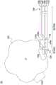
图1A绘示根据本发明的一实施例的电子装置的剖面图。FIG. 1A is a cross-sectional view of an electronic device according to an embodiment of the invention.
图1B为图1A的区域R的放大示意图。FIG. 1B is an enlarged schematic view of a region R in FIG. 1A .
图2A绘示根据本发明的另一实施例的电子装置的剖面图。FIG. 2A is a cross-sectional view of an electronic device according to another embodiment of the present invention.
图2B绘示根据本发明的另一实施例的电子装置的剖面图。FIG. 2B is a cross-sectional view of an electronic device according to another embodiment of the present invention.
图3绘示根据本发明的另一实施例的电子装置的剖面图。FIG. 3 is a cross-sectional view of an electronic device according to another embodiment of the present invention.
主要附图标记说明:Explanation of main reference signs:
10、20、30、40-电子装置,100可挠式显示器,102卷轴,102a外表面,102b-导圆角,102r-凹部,104-驱动基板,104a-顶面,106-显示层,108-前保护层,110-后保护层,112-胶层,114-胶层,116-固定槽,116a-内壁,118-容置槽,118a-底壁,120-伸缩组件,122-弹性件,122a-第一端,122b-第二端,124-活动件,124a-弹性面,124b-侧壁,124c-导圆角,126-粘着层,126a-顶面,126b-底面,216-固定槽,220-伸缩组件,222-弹性件,224-活动件,B-本体部,C-圆心,E-端部,R-区域,S-距离,T1、T2-厚度。10, 20, 30, 40-electronic device, 100 flexible display, 102 scroll, 102a outer surface, 102b-lead fillet, 102r-recess, 104-drive substrate, 104a-top surface, 106-display layer, 108 -front protective layer, 110-rear protective layer, 112-adhesive layer, 114-adhesive layer, 116-fixing groove, 116a-inner wall, 118-accommodating groove, 118a-bottom wall, 120-telescopic component, 122-elastic part , 122a-first end, 122b-second end, 124-movable member, 124a-elastic surface, 124b-side wall, 124c-fillet, 126-adhesive layer, 126a-top surface, 126b-bottom surface, 216- Fixed groove, 220-telescopic component, 222-elastic part, 224-movable part, B-body part, C-center of circle, E-end, R-area, S-distance, T1, T2-thickness.
具体实施方式Detailed ways
以下将以附图公开本发明的多个实施方式,为明确说明,许多实务上的细节将在以下叙述中一并说明。然而,应了解到,这些实务上的细节不应用以限制本发明。也就是说,在本发明部分实施方式中,这些实务上的细节是非必要的。此外,为简化附图起见,一些公知惯用的结构与元件在附图中将以简单示意的方式绘示。A number of embodiments of the present invention will be disclosed below with drawings, and many practical details will be described together in the following description for clarity. It should be understood, however, that these practical details should not be used to limit the invention. That is, in some embodiments of the present invention, these practical details are unnecessary. In addition, for the sake of simplifying the drawings, some well-known and commonly used structures and elements will be shown in a simple and schematic manner in the drawings.
图1A绘示根据本发明的一实施例的电子装置10的剖面图。图1B为图1A的区域R的放大示意图。请同时参照图1A及图1B。电子装置10包括可挠式显示器100以及卷轴102。可挠式显示器100具有本体部B及端部E,可挠式显示器100的端部E固定于卷轴102。卷轴102用以卷绕或展开可挠式显示器100。可挠式显示器100包括驱动基板104、显示层106、前保护层108及后保护层110。显示层106位于驱动基板104上,前保护层108覆盖显示层106,并通过胶层112贴附于驱动基板104的顶面104a。后保护层110位于驱动基板104的底面,并通过胶层114贴附于驱动基板104。前保护层108及后保护层110可用于防止水气渗入及紫外线进入显示层106及驱动基板104。在本实施例中,前保护层108的材质可以包括有机材料。FIG. 1A is a cross-sectional view of an
驱动基板104例如是主动元件阵列基板,但本发明不以此为限。具体来说,驱动基板104例如是由具有可挠性的塑胶或金属的材料所构成的薄膜驱动基板,使电子装置10更轻薄且便于携带。在本实施例中,显示层106可为电泳显示层。The driving
在本实施例中,卷轴102包括固定槽116。固定槽116凹设于卷轴102的外表面102a,并用以固定可挠式显示器100于卷轴102。可挠式显示器100的端部E位于固定槽116中。在本实施例中可挠式显示器100的端部E的厚度T1小于本体部B的厚度(例如本体部B的最小厚度T2)(见图1B),前保护层108的长度小于驱动基板104的长度,前保护层108不延伸至可挠式显示器100的端部E,换言之,前保护层108位于卷轴102的固定槽116外,如此一来,可挠式显示器100被卷轴102卷绕后的内径与外径之间的圆周长差值被降低,从而减少应力集中于可挠式显示器100的端部E,也避免了可挠式显示器100的膜层错位的问题。In this embodiment, the
此外,卷轴102还具有容置槽118与伸缩组件120。容置槽118凹设于卷轴102的外表面102a,且最靠近固定槽116的容置槽118与固定槽116彼此相隔距离S。伸缩组件120设置于容置槽118中,当卷轴102开始卷绕可挠式显示器100时,伸缩组件120可接触可挠式显示器100。在本实施例中,当伸缩组件120抵靠可挠式显示器100时,伸缩组件120可被压入容置槽118。在卷绕可挠式显示器100时,通过伸缩组件120朝卷轴102的圆心C方向溃缩,可避免可挠式显示器100在卷绕过程中产生应力集中,也避免了可挠式显示器100的膜层错位的问题。In addition, the
在本实施例中,伸缩组件120包括弹性件122及活动件124,弹性件122位于活动件124与卷轴102的圆心C之间。弹性件122的第一端122a位于容置槽118的底壁118a。活动件124位于弹性件122远离第一端122a的第二端122b上,用以抵靠可挠式显示器100。在可挠式显示器100被卷轴102卷绕的过程中,活动件124可抵靠可挠式显示器100,因此活动件124被压入容置槽118,也就是活动件124朝着卷轴102的圆心C移动,进而使得弹性件122朝卷轴102的圆心C被压缩。换言之,利用弹性件122产生弹性形变,弹性件122及活动件124可溃缩并吸收可挠式显示器100在卷绕过程中所产生的应力。在本实施例中,弹性件122可以为弹簧,但并不用以限制本发明,其他可伸缩的弹性材料也可作为弹性件122。In this embodiment, the
在本实施例中,活动件124具有背对弹性件122的弹性面124a,使活动件124的外表面有弹性而进一步提高了伸缩组件120的溃缩效果。此外,活动件124的弹性面124a与侧壁124b的连接处形成导圆角(round-corner)124c,可避免可挠式显示器100的端部E因为被弯折而断裂。In this embodiment, the
固定槽116具有内壁116a,卷轴102邻接内壁116a的外表面102a处具有导圆角102b。当可挠式显示器100被弯折时,接触导圆角102b的可挠式显示器100的端部E可受力均匀,因此避免了因应力过度集中于可挠式显示器100的端部E而使其断裂的风险。The fixing
在一实施例中,伸缩组件120的数量为多个,且伸缩组件120相对于卷轴102的圆心C呈对称排列。如此一来,在卷绕的过程中,可进一步降低应力集中于可挠式显示器100。In one embodiment, there are multiple
图2A绘示根据本发明的一实施例的电子装置20的剖面图。请参照图2A,电子装置20包括可挠式显示器100、卷轴102及粘着层126。粘着层126位于可挠式显示器100的端部E与卷轴102之间,以固定可挠式显示器100于卷轴102。FIG. 2A is a cross-sectional view of an electronic device 20 according to an embodiment of the present invention. Please refer to FIG. 2A , the electronic device 20 includes a
在本实施例中,卷轴102具有至少一个凹部102r,粘着层126位于可挠式显示器100的端部E与卷轴102的凹部102r之间,这样的配置可减少卷绕时的应力集中于可挠式显示器100的端部E。粘着层126具有相对的顶面126a与底面126b,粘着层126的顶面126a接触卷轴102的凹部102r。如此一来,即使卷绕后的可挠式显示器100因内径与外径之间的圆周长差异而产生应力,此应力也不会集中于可挠式显示器100在卷轴102的固定处。换言之,可降低应力集中于可挠式显示器100的端部E,也降低可挠式显示器100的膜层错位的风险。在本实施例中,由于可挠式显示器100的端部E的厚度T1小于本体部B的厚度(例如本体部B的最小厚度T2),前保护层108的长度小于驱动基板104的长度,前保护层108不延伸至可挠式显示器100的端部E,端部E如此一来,可挠式显示器100被卷轴102卷绕后的内径的圆周长与外径的圆周长之间的差值被降低,从而减少应力集中于可挠式显示器100的端部E,也避免了可挠式显示器100的膜层错位的问题。In this embodiment, the
当卷轴102开始卷绕可挠式显示器100时,凹部102r接触可挠式显示器100,因此可避免应力集中于可挠式显示器100,减少应力集中于可挠式显示器100的端部E。在一实施例中,凹部102r的数量为多个,凹部102r相对于卷轴102的圆心C呈对称排列,如此一来,在卷绕的过程中,可进一步降低应力集中于可挠式显示器100。When the
图2B绘示根据本发明的另一实施例的电子装置30的剖面图。本实施例的电子装置30与图2A的电子装置20的差异在于:卷轴102还包括伸缩组件220。伸缩组件220类似于图1A的伸缩组件120。伸缩组件220包括弹性件222及活动件224,弹性件222位于活动件224与卷轴102的圆心C之间,活动件224具有背对弹性件222的弹性面224a,使活动件224具有弹性能力而进一步提高了伸缩组件220的溃缩效果。伸缩组件220的其余细节于此不再赘述。在本实施例中,伸缩组件220与凹部102r相邻,在可挠式显示器100被卷轴102卷绕的过程中,伸缩组件220可接触可挠式显示器100。当伸缩组件220抵靠可挠式显示器100时,伸缩组件220被压入容置槽218,利用弹性件222产生弹性形变,弹性件222及活动件224可溃缩并吸收可挠式显示器100在卷绕过程中所产生的应力。FIG. 2B is a cross-sectional view of an
在一实施例中,伸缩组件220的数量为多个,伸缩组件220相对于卷轴102的圆心C呈对称排列。凹部102r的数量为多个,凹部102r相对于卷轴102的圆心C呈对称排列。举例而言,凹部102r与伸缩组件220呈间隔排列。在可挠式显示器100被卷轴102卷绕的过程中,伸缩组件220可先接触可挠式显示器100。当伸缩组件220抵靠可挠式显示器100时,伸缩组件220被压入容置槽118,利用弹性件222产生弹性形变,弹性件222及活动件224可溃缩并吸收可挠式显示器100在卷绕过程中所产生的应力。接着,凹部102r抵靠可挠式显示器100,因此可避免应力集中于可挠式显示器100,有效地降低可挠式显示器100因应力导致的膜层错位的风险。In one embodiment, there are multiple
图3绘示根据本发明的另一实施例的电子装置40的剖面图。本实施例的电子装置40与图2A的电子装置20的差异在于:电子装置40可以有粘着层126或省略粘着层126,且卷轴102包括固定槽216。固定槽216类似于图1A的固定槽116,因此固定槽216的细节于此不再赘述。在本实施例中,固定槽216位于凹部102r中,如此一来,在卷绕的过程中,可避免应力集中于可挠式显示器100的端部E,也避免可挠式显示器100的膜层错位的风险。FIG. 3 is a cross-sectional view of an
综上所述,本发明的实施例的电子装置中,通过使用具有固定槽的卷轴,可降低应力集中于可挠式显示器的端部,且由于可挠式显示器的端部的厚度小于本体部的厚度,可挠式显示器被卷轴卷绕后的内径与外径之间的圆周长差值被降低,从而减少应力集中于可挠式显示器的端部,也避免可挠式显示器的膜层错位。卷轴还具有设置于容置槽中的伸缩组件,当伸缩组件抵靠可挠式显示器时,伸缩组件被压入容置槽。通过使用具有伸缩组件的卷轴,在卷绕可挠式显示器时,通过伸缩组件朝卷轴的圆心方向溃缩,可避免可挠式显示器在卷绕过程中产生应力集中,也避免了可挠式显示器的膜层错位的问题。伸缩组件还包括活动件与弹性件。活动件具有背对弹性件的弹性面,且弹性面与活动件的一侧壁的连接处形成导圆角,可避免位于固定槽的可挠式显示器的端部因为被弯折而断裂。卷轴邻接内壁的外表面处具有导圆角。当可挠式显示器被弯折时,接触导圆角的可挠式显示器可受力均匀,因此避免了因应力过度集中于可挠式显示器的端部而使其断裂的风险。To sum up, in the electronic device of the embodiment of the present invention, by using the reel with the fixing groove, the stress concentration on the end of the flexible display can be reduced, and since the thickness of the end of the flexible display is smaller than that of the main body The thickness, the circumference difference between the inner diameter and the outer diameter of the flexible display after being wound by the reel is reduced, thereby reducing the stress concentration on the end of the flexible display and avoiding the misalignment of the film layer of the flexible display . The reel also has a telescopic assembly arranged in the accommodation groove, and when the telescopic assembly abuts against the flexible display, the telescopic assembly is pressed into the accommodation groove. By using a reel with a telescopic component, when the flexible display is wound, the telescopic component collapses toward the center of the reel, thereby avoiding stress concentration of the flexible display during the winding process, and also avoiding the The problem of misalignment of the film layer. The telescopic assembly also includes movable parts and elastic parts. The movable part has an elastic surface facing away from the elastic part, and the connection between the elastic surface and the side wall of the movable part forms a fillet, which can prevent the end of the flexible display located in the fixing groove from being broken due to being bent. The outer surface of the spool adjoining the inner wall has a fillet. When the flexible display is bent, the flexible display contacting the rounded corners can be evenly stressed, thus avoiding the risk of breaking the flexible display due to excessive stress concentrated on the end of the flexible display.
虽然本发明已以实施方式公开如上,然其并非用以限定本发明,任何本领域的技术人员,在不脱离本发明的精神和范围内,当可作各种的更动与润饰,因此本发明的保护范围当视权利要求所界定的为准。Although the present invention has been disclosed above in terms of implementation, it is not intended to limit the present invention. Any person skilled in the art may make various changes and modifications without departing from the spirit and scope of the present invention. Therefore, this The scope of protection of the invention should be defined by the claims.
Claims (13)
Translated fromChinesePriority Applications (1)
| Application Number | Priority Date | Filing Date | Title |
|---|---|---|---|
| CN201910862053.7ACN112489557B (en) | 2019-09-12 | 2019-09-12 | Electronic device |
Applications Claiming Priority (1)
| Application Number | Priority Date | Filing Date | Title |
|---|---|---|---|
| CN201910862053.7ACN112489557B (en) | 2019-09-12 | 2019-09-12 | Electronic device |
Publications (2)
| Publication Number | Publication Date |
|---|---|
| CN112489557A CN112489557A (en) | 2021-03-12 |
| CN112489557Btrue CN112489557B (en) | 2023-03-31 |
Family
ID=74920741
Family Applications (1)
| Application Number | Title | Priority Date | Filing Date |
|---|---|---|---|
| CN201910862053.7AActiveCN112489557B (en) | 2019-09-12 | 2019-09-12 | Electronic device |
Country Status (1)
| Country | Link |
|---|---|
| CN (1) | CN112489557B (en) |
Families Citing this family (1)
| Publication number | Priority date | Publication date | Assignee | Title |
|---|---|---|---|---|
| CN114203046B (en)* | 2021-12-20 | 2024-06-11 | 云谷(固安)科技有限公司 | Support assembly, display device and control method thereof |
Citations (3)
| Publication number | Priority date | Publication date | Assignee | Title |
|---|---|---|---|---|
| CN101008760A (en)* | 2006-01-23 | 2007-08-01 | 精工爱普生株式会社 | Electrophoretic display sheet, electrophoretic display device, and electronic apparatus |
| TW201227639A (en)* | 2010-12-29 | 2012-07-01 | Ind Tech Res Inst | Flexible display apparatus and fabrication method of flexible display apparatus |
| CN108877530A (en)* | 2018-04-30 | 2018-11-23 | 友达光电股份有限公司 | Flexible display |
Family Cites Families (17)
| Publication number | Priority date | Publication date | Assignee | Title |
|---|---|---|---|---|
| KR102245808B1 (en)* | 2014-02-12 | 2021-04-30 | 삼성디스플레이 주식회사 | Rollable display apparatus |
| CN104407675B (en)* | 2014-12-12 | 2017-07-28 | 京东方科技集团股份有限公司 | Display screen reel system and its control method |
| EP3239965A4 (en)* | 2014-12-25 | 2018-07-11 | Shenzhen Royole Technologies Co., Ltd. | Flexible display device |
| US10365691B2 (en)* | 2015-04-09 | 2019-07-30 | Samsung Electronics Co., Ltd. | Foldable device |
| KR102333180B1 (en)* | 2015-08-05 | 2021-11-30 | 삼성전자주식회사 | Electronic apparatus having a flexible display |
| KR102427669B1 (en)* | 2015-11-17 | 2022-08-02 | 삼성디스플레이 주식회사 | Flexible display device |
| CN107408358B (en)* | 2015-12-30 | 2020-06-23 | 深圳市柔宇科技有限公司 | Scroll type flexible display |
| KR102471116B1 (en)* | 2016-05-12 | 2022-11-28 | 삼성디스플레이 주식회사 | Rollable display |
| KR102546825B1 (en)* | 2016-07-06 | 2023-06-23 | 삼성디스플레이 주식회사 | Rollable display device |
| US10775849B2 (en)* | 2016-09-20 | 2020-09-15 | Sharp Kabushiki Kaisha | Flexible device and method for manufacturing same |
| CN107067981A (en)* | 2017-04-17 | 2017-08-18 | 京东方科技集团股份有限公司 | Flexible display apparatus and mobile terminal |
| CN107331301A (en)* | 2017-08-08 | 2017-11-07 | 武汉华星光电半导体显示技术有限公司 | A kind of flexible display apparatus |
| CN107393424B (en)* | 2017-09-15 | 2019-05-03 | 武汉华星光电半导体显示技术有限公司 | A kind of collapsible component and flexible display apparatus |
| TWI648717B (en)* | 2017-10-26 | 2019-01-21 | 元太科技工業股份有限公司 | Flexible electronic device |
| CN108230937B (en)* | 2018-03-26 | 2024-09-10 | 京东方科技集团股份有限公司 | Flexible display device |
| CN109872639B (en)* | 2019-04-25 | 2021-04-20 | 京东方科技集团股份有限公司 | rollable display |
| CN110211506B (en)* | 2019-07-04 | 2021-08-06 | 京东方科技集团股份有限公司 | scroll display |
- 2019
- 2019-09-12CNCN201910862053.7Apatent/CN112489557B/enactiveActive
Patent Citations (3)
| Publication number | Priority date | Publication date | Assignee | Title |
|---|---|---|---|---|
| CN101008760A (en)* | 2006-01-23 | 2007-08-01 | 精工爱普生株式会社 | Electrophoretic display sheet, electrophoretic display device, and electronic apparatus |
| TW201227639A (en)* | 2010-12-29 | 2012-07-01 | Ind Tech Res Inst | Flexible display apparatus and fabrication method of flexible display apparatus |
| CN108877530A (en)* | 2018-04-30 | 2018-11-23 | 友达光电股份有限公司 | Flexible display |
Also Published As
| Publication number | Publication date |
|---|---|
| CN112489557A (en) | 2021-03-12 |
Similar Documents
| Publication | Publication Date | Title |
|---|---|---|
| CN109887419B (en) | A display device | |
| US11288986B2 (en) | Film for display device, display device including the same, and manufacturing method thereof | |
| JP2006507543A (en) | Flexible display | |
| KR101935553B1 (en) | A flexible display device and the manufacturing method thereof | |
| CN109407196B (en) | Polaroid, flexible display panel and flexible display device | |
| CN111862825A (en) | display device | |
| US20050195462A1 (en) | Interference display plate and manufacturing method thereof | |
| KR20150095075A (en) | Rollable display apparatus | |
| US11492289B2 (en) | Foldable glass substrate and foldable display device including the same | |
| CN111369897B (en) | Foldable display screen and foldable electronic equipment | |
| US12169297B2 (en) | Polarizing structure, modular structure, and manufacturing method thereof | |
| CN112489557B (en) | Electronic device | |
| WO2019064488A1 (en) | Elastic support substrate for flexible display, flexible display, and flexible display laminate | |
| US20230236627A1 (en) | Display panel | |
| US20240402763A1 (en) | Display module and display device | |
| WO2017104364A1 (en) | Glass roll and method for manufacturing same | |
| CN110992836B (en) | Display module and display device | |
| CN111048549B (en) | Display panel, display device and preparation method of display panel | |
| US20070228000A1 (en) | Encapsulation cap and display device including the same | |
| TWI726417B (en) | Electronic apparatus | |
| JP2000203630A (en) | Embossed carrier tape and embossed carrier taping method | |
| WO2017163885A1 (en) | Cover assembly, hard disk device, and method for manufacturing same | |
| EP4009311B1 (en) | Display apparatus and assembly method therefor | |
| CN212256772U (en) | display device | |
| JP2006261416A (en) | Semiconductor capacitor |
Legal Events
| Date | Code | Title | Description |
|---|---|---|---|
| PB01 | Publication | ||
| PB01 | Publication | ||
| SE01 | Entry into force of request for substantive examination | ||
| SE01 | Entry into force of request for substantive examination | ||
| GR01 | Patent grant | ||
| GR01 | Patent grant |