CN112489132B - Calibration system and method for a large-scale object measuring robot - Google Patents
Calibration system and method for a large-scale object measuring robotDownload PDFInfo
- Publication number
- CN112489132B CN112489132BCN202011268881.7ACN202011268881ACN112489132BCN 112489132 BCN112489132 BCN 112489132BCN 202011268881 ACN202011268881 ACN 202011268881ACN 112489132 BCN112489132 BCN 112489132B
- Authority
- CN
- China
- Prior art keywords
- calibration
- camera
- target
- calibration plate
- coordinate system
- Prior art date
- Legal status (The legal status is an assumption and is not a legal conclusion. Google has not performed a legal analysis and makes no representation as to the accuracy of the status listed.)
- Active
Links
Images


Classifications
- G—PHYSICS
- G06—COMPUTING OR CALCULATING; COUNTING
- G06T—IMAGE DATA PROCESSING OR GENERATION, IN GENERAL
- G06T7/00—Image analysis
- G06T7/80—Analysis of captured images to determine intrinsic or extrinsic camera parameters, i.e. camera calibration
- G06T7/85—Stereo camera calibration
- G—PHYSICS
- G06—COMPUTING OR CALCULATING; COUNTING
- G06T—IMAGE DATA PROCESSING OR GENERATION, IN GENERAL
- G06T7/00—Image analysis
- G06T7/20—Analysis of motion
- G06T7/246—Analysis of motion using feature-based methods, e.g. the tracking of corners or segments
- G—PHYSICS
- G06—COMPUTING OR CALCULATING; COUNTING
- G06T—IMAGE DATA PROCESSING OR GENERATION, IN GENERAL
- G06T2207/00—Indexing scheme for image analysis or image enhancement
- G06T2207/10—Image acquisition modality
- G06T2207/10028—Range image; Depth image; 3D point clouds
Landscapes
- Engineering & Computer Science (AREA)
- Computer Vision & Pattern Recognition (AREA)
- Physics & Mathematics (AREA)
- General Physics & Mathematics (AREA)
- Theoretical Computer Science (AREA)
- Multimedia (AREA)
- Length Measuring Devices By Optical Means (AREA)
Abstract
Description
Translated fromChinese技术领域technical field
本发明创造属于物体测量机器人领域,尤其是涉及一种大尺寸物体测量机器人标定系统及方法。The invention belongs to the field of object measuring robots, and in particular relates to a calibration system and method for a large-scale object measuring robot.
背景技术Background technique
在现有技术中,利用手眼标定方法对测量机器人进行实时标定,保证测量物体时的准确度和精确度,手眼标定中的体系关系转化主要是机器座、机械臂、机械臂末端的摄像头以及待测物体之间的关系,但是此种方式弊端在于如测量大尺寸物体时就会发生机器座不能仅仅处于一个固定位置,进而产生位移,此时整体已经构建起来的体系关系就会发生变化,从而重新进行关系测算,不利于测量效率。In the existing technology, the hand-eye calibration method is used to calibrate the measuring robot in real time to ensure the accuracy and precision when measuring objects. The relationship between objects can be measured, but the disadvantage of this method is that when measuring large-sized objects, the machine base cannot only be in a fixed position, and then produce displacement. At this time, the system relationship that has been built as a whole will change, thus Re-calculating the relationship is not conducive to measuring efficiency.
发明内容Contents of the invention
有鉴于此,本发明创造旨在提出一种大尺寸物体测量机器人标定系统及方法,以解决在观测获取大尺寸物体时测量机器人的手眼标定观测摄像头超出范围后重新调整整体机器人所在位置而使得整体标定转化关系发生变化的问题。In view of this, the present invention aims to propose a large-scale object measurement robot calibration system and method to solve the problem of readjusting the position of the overall robot after the hand-eye calibration observation camera of the measurement robot is out of range when the large-scale object is observed and acquired. The problem of changing the calibration conversion relationship.
为达到上述目的,本发明创造的技术方案是这样实现的:In order to achieve the above object, the technical solution created by the present invention is achieved in this way:
一种大尺寸物体测量机器人标定系统,其包括机械臂、位于机械臂末端的测量摄像机、标定板、跟踪摄像机和靶标;A calibration system for a large-scale object measuring robot, which includes a robotic arm, a measuring camera positioned at the end of the robotic arm, a calibration plate, a tracking camera and a target;
在机械臂上设有用于标定的靶标,所述靶标位置与测量摄像机相对固定;A target for calibration is provided on the mechanical arm, and the position of the target is fixed relative to the measurement camera;
在测量摄像机可测量位置处放置有标定板;A calibration plate is placed at the measurable position of the measuring camera;
对应靶标位置设置跟踪摄像机,所述跟踪摄像机与标定板位置相对固定。A tracking camera is set corresponding to the position of the target, and the position of the tracking camera and the calibration plate is relatively fixed.
进一步的,所述标定板上设置有用于确定标定板位姿的球体。Further, the calibration board is provided with a sphere for determining the pose of the calibration board.
进一步的,所述靶标设置在机械臂末端。Further, the target is set at the end of the mechanical arm.
进一步的,所述靶标设置在机械臂末端并罩在测量摄像机外部。Further, the target is set at the end of the mechanical arm and is covered outside the measuring camera.
进一步的,所述机械臂搭载在自动导引运输装置上。Further, the robotic arm is mounted on an automatic guided transport device.
进一步的,所述标定板为具有均匀网格的板材,所述标定板上设置有用于确定标定板位姿的球体。Further, the calibration plate is a plate with a uniform grid, and the calibration plate is provided with a sphere for determining the pose of the calibration plate.
进一步的,测量摄像机为双目相机的镜头,跟踪摄像机为单目相机的镜头。Further, the measurement camera is a lens of a binocular camera, and the tracking camera is a lens of a monocular camera.
一种大尺寸物体测量机器人标定方法,以跟踪摄像机所在位置建立世界坐标系,标定板自身建立标定坐标系,测量摄像机所在位置建立测量坐标系;A method for calibrating a large-scale object measuring robot, in which a world coordinate system is established by tracking the position of a camera, the calibration board itself establishes a calibration coordinate system, and the position of the camera is measured to establish a measurement coordinate system;
首先,将标定板放置在测量摄像机可测量范围内,用测量摄像机拍摄标定板的图像并标定测量摄像机外参数,计算测量坐标系与标定坐标系之间的转化关系B;Firstly, place the calibration plate within the measurable range of the measurement camera, use the measurement camera to take images of the calibration plate and calibrate the external parameters of the measurement camera, and calculate the conversion relationship B between the measurement coordinate system and the calibration coordinate system;
其次,标定板与跟踪摄像机之间的位置关系相对固定,标定坐标系与世界坐标系之间的转化关系为C,靶标与测量摄像机之间的位置关系相对固定,其两者之间的转化关系为X;Secondly, the positional relationship between the calibration board and the tracking camera is relatively fixed, the transformation relationship between the calibration coordinate system and the world coordinate system is C, the positional relationship between the target and the measurement camera is relatively fixed, and the transformation relationship between them for X;
而后,在标定板上标定三个特征角点,并以其中一特征点为起点,沿标定板所在平面的水平和垂直方向平移至另外两个特征点,利用测量摄像机得到标定板上三个特征角点的坐标,通过平面公式表示为标定坐标;Then, mark three feature corner points on the calibration board, and start from one of the feature points, translate to the other two feature points along the horizontal and vertical directions of the plane where the calibration board is located, and use the measurement camera to obtain the three feature points on the calibration board. The coordinates of the corner points are expressed as calibration coordinates through the plane formula;
此时跟踪摄像机会测量到靶标随着测量摄像机测量移动而发生的位置变化,靶标与跟踪摄像机之间的转化关系为A;At this time, the tracking camera will measure the position change of the target as the measurement camera moves, and the conversion relationship between the target and the tracking camera is A;
最后,根据靶标与跟踪摄像机之间的转化关系为A和测量坐标系与标定坐标系之间的转化关系B计算得到靶标与测量摄像机之间的转化关系X。Finally, according to the conversion relationship A between the target and the tracking camera and the conversion relationship B between the measurement coordinate system and the calibration coordinate system, the conversion relationship X between the target and the measurement camera is calculated.
进一步的,选择为起点的特征角位于标定板的左上角点,另外两个特征点分别分布在该起点特征点的横轴和纵轴方向上。Further, the characteristic corner selected as the starting point is located at the upper left corner of the calibration board, and the other two characteristic points are respectively distributed in the horizontal and vertical directions of the starting point characteristic point.
进一步的,靶标与测量摄像机之间的转化关系通过转换矩阵进行表示,转换矩阵包括旋转矩阵和平移矩阵。Further, the transformation relationship between the target and the measurement camera is represented by a transformation matrix, which includes a rotation matrix and a translation matrix.
进一步的,计算得到靶标与测量摄像机之间的转化关系X利用TSAI、PARK或者HORAUD非线性优化方法。Further, the calculated conversion relationship X between the target and the measurement camera uses TSAI, PARK or HORAUD nonlinear optimization methods.
进一步的,标定坐标系与世界坐标系之间的转化关系为C=AXB;Further, the conversion relationship between the calibration coordinate system and the world coordinate system is C=AXB;
分别测量两次不同标定板中的特征角点,即可得到C=A1XB1=A2XB2 (1);Measure the characteristic corner points in different calibration boards twice respectively, and you can get C=A1 XB1 =A2 XB2 (1);
根据公式一进行变换得到公式二:A-12A1X=XB2B-11 (2);Transform according to
通过公式二最终即可得到公式三AX=XB (3);Through the formula two, the formula three AX=XB can be finally obtained (3);
利用公式三选择TSAI、PARK或者HORAUD非线性优化中的一种计算方式即可得到X。Use
进一步的,所述标定板上固定有用于确定标定板位姿的三个球体;Further, three spheres for determining the pose of the calibration board are fixed on the calibration board;
设三个球体的球心分别为O、X、Y,其中OX与OY相互垂直,喷涂显影剂后用测量摄像机进行扫描,获取标定板在测量区域的点云数据;Let the centers of the three spheres be O, X, and Y respectively, where OX and OY are perpendicular to each other. After spraying the developer, use the measuring camera to scan to obtain the point cloud data of the calibration plate in the measuring area;
将点云数据导入Geomagic软件,通过拟合可以得到三个球体的球心坐标;计算时


进一步的,考虑到手动在标定板上设置球体时,可能无法严格意义上保证球心之间连线相互垂直,所以需要从算法上进行改善。计算时,先通过O点和X点得到OX直线方程,再计算三维空间中点Y到直线OX的垂足O’,将O’作为新的原点代入上面以O点为原点建立空间坐标系的计算过程,从而保证得到的

相对于现有技术,本发明创造所述的一种大尺寸物体测量机器人标定系统及方法具有以下优势:Compared with the prior art, the invention creates a calibration system and method for a large-scale object measuring robot that has the following advantages:
本发明所述的标定系统及方法可以有效解决机器人发生位移时体系关系发生变化的问题,由于采用的是跟踪摄像机与标定板之间的相对固定位置关系,以及靶标与测量摄像机之间的固定位置关系,从而得到整个体系之间的转化关系,那么即便机器人发生位移,机器臂也发生位移,跟踪摄像机与靶标之间的位置以及靶标与测量摄像机之间的位置均不会发生改变,也就避免了重新构建模型,建立体系关系的问题。The calibration system and method described in the present invention can effectively solve the problem that the system relationship changes when the robot is displaced, because the relative fixed position relationship between the tracking camera and the calibration plate, and the fixed position between the target and the measurement camera are adopted. relationship, so as to obtain the transformation relationship between the entire system, then even if the robot moves, the robot arm also moves, and the position between the tracking camera and the target and the position between the target and the measuring camera will not change, thus avoiding It solves the problem of rebuilding the model and establishing the system relationship.
标定系统的结构配合关系也是为了实现上述目的而进行的创新。The structural coordination relationship of the calibration system is also an innovation to achieve the above-mentioned purpose.
附图说明Description of drawings
构成本发明创造的一部分的附图用来提供对本发明创造的进一步理解,本发明创造的示意性实施例及其说明用于解释本发明创造,并不构成对本发明创造的不当限定。在附图中:The accompanying drawings constituting a part of the present invention are used to provide a further understanding of the present invention, and the schematic embodiments and descriptions of the present invention are used to explain the present invention and do not constitute improper limitations to the present invention. In the attached picture:
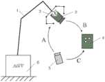
图1为本发明创造实施例所述的大尺寸物体测量机器人标定系统示意图;Fig. 1 is a schematic diagram of a calibration system for a large-scale object measuring robot described in an embodiment of the present invention;
图2为本发明创造实施例所述的标定板结构示意图;Fig. 2 is a schematic structural diagram of a calibration plate described in an embodiment of the present invention;
图3为本发明创造实施例所述的使用不同计算法则得到的X数据图;Fig. 3 is the X data diagram obtained by using different calculation rules described in the inventive embodiment of the present invention;
图4为本发明创造实施例所述的TSAI计算法正向验证数据;Fig. 4 is the forward verification data of the TSAI calculation method described in the inventive embodiment of the present invention;
图5为本发明创造实施例所述的PARK计算法正向验证数据;Figure 5 is the forward verification data of the PARK calculation method described in the inventive embodiment;
图6为本发明创造实施例所述的HORAUD非线性计算法正向验证数据。Fig. 6 is the forward verification data of the HORAUD nonlinear calculation method described in the inventive embodiment of the present invention.
附图标记说明:Explanation of reference signs:
1-机械臂;2-靶标(跟踪立体靶标);3-测量摄像机(双目测量系统);4-标定板;5-跟踪摄像机(单目跟踪系统);6-AGV。1-mechanical arm; 2-target (tracking stereo target); 3-measurement camera (binocular measurement system); 4-calibration board; 5-tracking camera (monocular tracking system); 6-AGV.
具体实施方式Detailed ways
需要说明的是,在不冲突的情况下,本发明创造中的实施例及实施例中的特征可以相互组合。It should be noted that, in the case of no conflict, the embodiments of the present invention and the features in the embodiments can be combined with each other.
在本发明创造的描述中,需要理解的是,术语“中心”、“纵向”、“横向”、“上”、“下”、“前”、“后”、“左”、“右”、“竖直”、“水平”、“顶”、“底”、“内”、“外”等指示的方位或位置关系为基于附图所示的方位或位置关系,仅是为了便于描述本发明创造和简化描述,而不是指示或暗示所指的装置或元件必须具有特定的方位、以特定的方位构造和操作,因此不能理解为对本发明创造的限制。此外,术语“第一”、“第二”等仅用于描述目的,而不能理解为指示或暗示相对重要性或者隐含指明所指示的技术特征的数量。由此,限定有“第一”、“第二”等的特征可以明示或者隐含地包括一个或者更多个该特征。在本发明创造的描述中,除非另有说明,“多个”的含义是两个或两个以上。In describing the present invention, it should be understood that the terms "center", "longitudinal", "transverse", "upper", "lower", "front", "rear", "left", "right", The orientations or positional relationships indicated by "vertical", "horizontal", "top", "bottom", "inner", "outer", etc. are based on the orientation or positional relationship shown in the drawings, and are only for the convenience of describing the present invention Creation and simplification of description, rather than indicating or implying that the device or element referred to must have a specific orientation, be constructed and operate in a specific orientation, and therefore should not be construed as limiting the invention. In addition, the terms "first", "second", etc. are used for descriptive purposes only, and should not be understood as indicating or implying relative importance or implicitly specifying the quantity of the indicated technical features. Thus, a feature defined as "first", "second", etc. may expressly or implicitly include one or more of that feature. In the description of the present invention, unless otherwise specified, "plurality" means two or more.
在本发明创造的描述中,需要说明的是,除非另有明确的规定和限定,术语“安装”、“相连”、“连接”应做广义理解,例如,可以是固定连接,也可以是可拆卸连接,或一体地连接;可以是机械连接,也可以是电连接;可以是直接相连,也可以通过中间媒介间接相连,可以是两个元件内部的连通。对于本领域的普通技术人员而言,可以通过具体情况理解上述术语在本发明创造中的具体含义。In the description of the present invention, it should be noted that unless otherwise specified and limited, the terms "installation", "connection" and "connection" should be interpreted in a broad sense, for example, it can be a fixed connection or a flexible connection. Detachable connection, or integral connection; it can be mechanical connection or electrical connection; it can be direct connection or indirect connection through an intermediary, and it can be the internal communication of two components. Those of ordinary skill in the art can understand the specific meanings of the above terms in the present invention based on specific situations.
下面将参考附图并结合实施例来详细说明本发明创造。The invention will be described in detail below with reference to the accompanying drawings and examples.
如图1所示,一种大尺寸物体测量机器人标定系统,其包括机械臂、位于机械臂末端的测量摄像机、标定板、跟踪摄像机和靶标;As shown in Figure 1, a large-scale object measurement robot calibration system, which includes a mechanical arm, a measurement camera located at the end of the mechanical arm, a calibration plate, a tracking camera and a target;
在机械臂上设有用于标定的靶标,该靶标带有特征光源,用于引导测量空间外跟踪摄像机进行实时的高精度跟踪,所述靶标位置与测量摄像机相对固定;A target for calibration is provided on the mechanical arm, and the target has a characteristic light source, which is used to guide the tracking camera outside the measurement space to perform real-time high-precision tracking, and the position of the target is relatively fixed with the measurement camera;
在测量摄像机可测量位置处放置有标定板;A calibration plate is placed at the measurable position of the measuring camera;
对应靶标位置设置跟踪摄像机,所述跟踪摄像机与标定板位置相对固定。A tracking camera is set corresponding to the position of the target, and the position of the tracking camera and the calibration plate is relatively fixed.
所述靶标设置在机械臂末端。The target is set at the end of the mechanical arm.
所述靶标设置在机械臂末端并罩在测量摄像机外部。The target is arranged at the end of the mechanical arm and is covered outside the measuring camera.
所述机械臂搭载在自动导引运输装置上。The robotic arm is mounted on an automatic guided transport device.
所述标定板为具有均匀网格的板材,所述标定板上设置有用于确定标定板位姿的球体。The calibration plate is a plate with a uniform grid, and a sphere for determining the pose of the calibration plate is arranged on the calibration plate.
测量摄像机为双目相机的镜头,跟踪摄像机为单目相机的镜头。The measurement camera is the lens of the binocular camera, and the tracking camera is the lens of the monocular camera.
这里面使用到的靶标带有特征光源。The targets used here have characteristic light sources.
一种大尺寸物体测量机器人标定方法,以跟踪摄像机所在位置建立世界坐标系,标定板自身建立标定坐标系,测量摄像机所在位置建立测量坐标系;A method for calibrating a large-scale object measuring robot, in which a world coordinate system is established by tracking the position of a camera, the calibration board itself establishes a calibration coordinate system, and the position of the camera is measured to establish a measurement coordinate system;
首先,将标定板放置在测量摄像机可测量范围内,用测量摄像机拍摄标定板的图像并标定测量摄像机外参数,计算测量坐标系与标定坐标系之间的转化关系B;Firstly, place the calibration plate within the measurable range of the measurement camera, use the measurement camera to take images of the calibration plate and calibrate the external parameters of the measurement camera, and calculate the conversion relationship B between the measurement coordinate system and the calibration coordinate system;
其次,标定板与跟踪摄像机之间的位置关系相对固定,标定坐标系与世界坐标系之间的转化关系为C,靶标与测量摄像机之间的位置关系相对固定,其两者之间的转化关系为X;Secondly, the positional relationship between the calibration board and the tracking camera is relatively fixed, the transformation relationship between the calibration coordinate system and the world coordinate system is C, the positional relationship between the target and the measurement camera is relatively fixed, and the transformation relationship between them for X;
而后,在标定板上标定三个特征角点,并以其中一特征角点为起点平移至另外两个特征角点,利用测量摄像机得到标定板上三个特征角点的坐标,即为标定位姿坐标;优选的,选择为起点的特征角位于标定板的左上角点,另外两个特征点分别分布在该起点特征点的横轴和纵轴方向上。Then, calibrate three characteristic corner points on the calibration board, and use one of the characteristic corner points as the starting point to translate to the other two characteristic corner points, and use the measurement camera to obtain the coordinates of the three characteristic corner points on the calibration board, which is the calibration position Attitude coordinates; preferably, the characteristic angle selected as the starting point is located at the upper left corner of the calibration board, and the other two characteristic points are respectively distributed on the horizontal axis and the vertical axis direction of the starting point characteristic point.
上述标定板的三个特征角点可使用球体来替代,所述标定板上固定有用于确定标定板位姿的三个球体;The three characteristic corner points of the above-mentioned calibration board can be replaced by spheres, and the three spheres used to determine the pose of the calibration board are fixed on the calibration board;
设三个球体的球心分别为O、X、Y,其中OX与OY相互垂直,喷涂显影剂后用测量摄像机进行扫描,获取标定板在测量区域的点云数据;Let the centers of the three spheres be O, X, and Y respectively, where OX and OY are perpendicular to each other. After spraying the developer, use the measuring camera to scan to obtain the point cloud data of the calibration plate in the measuring area;
将点云数据导入Geomagic软件,通过拟合可以得到三个球体的球心坐标;计算时


考虑到手动在标定板上设置球体时,可能无法严格意义上保证连线相互垂直,所以需要从算法上进行改善。计算时,先通过O点和X点得到OX直线方程,再计算三维空间中点Y到直线OX的垂足O’,将O’作为新的原点代入上面以O点为原点建立空间坐标系的计算过程,O’是Y到OX的垂足,从而保证得到的

在求解靶标与跟踪摄像机的坐标转换关系A时,通过靶标具有跟踪特性的系统可以得到跟踪摄像机视野范围内特征光源的空间坐标,结合靶标本身几何信息,可以生成若干(五个)特征坐标,它们不属于同一条直线上,相对位置保持不变,反映了靶标上若干固定位置的空间信息,而通过其中三点即可确定一个平面。从五个特征坐标中取第一、第三、第五个点分别作为O点、X点、Y点,通过作垂线求解新原点O’的过程与上述求解过程相同,然后代入公式四得到平面位姿。When solving the coordinate transformation relationship A between the target and the tracking camera, the spatial coordinates of the characteristic light sources within the field of view of the tracking camera can be obtained through the system with the tracking characteristics of the target, combined with the geometric information of the target itself, several (five) characteristic coordinates can be generated. Not belonging to the same straight line, the relative position remains unchanged, reflecting the spatial information of several fixed positions on the target, and a plane can be determined through three of them. Take the first, third, and fifth points from the five characteristic coordinates as point O, point X, and point Y respectively. The process of solving the new origin O' by making a vertical line is the same as the above-mentioned solution process, and then substituting it into
此时跟踪摄像机会测量到靶标随着测量摄像机测量移动而发生的位置变化,靶标与跟踪摄像机之间的转化关系为A;At this time, the tracking camera will measure the position change of the target as the measurement camera moves, and the conversion relationship between the target and the tracking camera is A;
最后,根据靶标与跟踪摄像机之间的转化关系为A和测量坐标系与标定坐标系之间的转化关系B计算得到靶标与测量摄像机之间的转化关系X。Finally, according to the conversion relationship A between the target and the tracking camera and the conversion relationship B between the measurement coordinate system and the calibration coordinate system, the conversion relationship X between the target and the measurement camera is calculated.
进一步的,靶标与测量摄像机之间的转化关系通过转换矩阵进行表示,转换矩阵包括旋转矩阵和平移矩阵。Further, the transformation relationship between the target and the measurement camera is represented by a transformation matrix, which includes a rotation matrix and a translation matrix.
标定坐标系与世界坐标系之间的转化关系为C=AXB;The conversion relationship between the calibration coordinate system and the world coordinate system is C=AXB;
分别测量两次不同标定板中的特征角点,即可得到C=A1XB1=A2XB2 (1);Measure the characteristic corner points in different calibration boards twice respectively, and you can get C=A1 XB1 =A2 XB2 (1);
根据公式一进行变换得到公式二:A-12A1X=XB2B-11 (2);Transform according to
通过公式二最终即可得到公式三AX=XB (3);Through the formula two, the formula three AX=XB can be finally obtained (3);
利用公式三选择TSAI、PARK或者HORAUD非线性优化中的一种计算方式即可得到X。Use
所以整个系统的总输入有:So the total input to the whole system is:
a.测量摄像头扫描标定板上球体的点云数据;a. The measurement camera scans the point cloud data of the sphere on the calibration board;
b.跟踪摄像头拍摄计算得到的靶标特征坐标数据。b. The tracking camera captures the calculated target feature coordinate data.
在实际操作中,一般控制机械臂处于不同位姿,且使得测量摄像机距离标定板在15-20cm范围内,采集尽量多的数据进行运算,最后得到标定结果:测量摄像机与靶标的转换关系X。In actual operation, the manipulator is generally controlled to be in different poses, and the distance between the measurement camera and the calibration plate is within 15-20cm, and as much data as possible is collected for calculation, and finally the calibration result is obtained: the conversion relationship X between the measurement camera and the target.
以下根据上述标定系统和方法进行了测试:The following tests were performed according to the calibration system and method described above:
采集25组数据,通过以上方法得到X:Collect 25 sets of data, and get X through the above method:
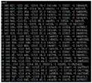
使用到的A和B的原始数据为:The original data of A and B used are:
A:A:
(-249.119,-155.5,-2194.6,2.72931,0.154059,1.0178)(-249.119, -155.5, -2194.6, 2.72931, 0.154059, 1.0178)
(-255.275,-162.08,-2188.33,2.73864,0.0226353,1.00797)(-255.275, -162.08, -2188.33, 2.73864, 0.0226353, 1.00797)
(-224.049,-151.8,-2208.1,2.7674,0.054264,0.981255)(-224.049, -151.8, -2208.1, 2.7674, 0.054264, 0.981255)
(-233.228,-175.208,-2204.53,2.77525,0.0401564,1.01978)(-233.228, -175.208, -2204.53, 2.77525, 0.0401564, 1.01978)
(-242.129,-170.803,-2198.15,2.81669,-0.0923144,1.00188)(-242.129, -170.803, -2198.15, 2.81669, -0.0923144, 1.00188)
(-235.485,-205.62,-2204.29,2.80227,-0.0362794,1.09935)(-235.485, -205.62, -2204.29, 2.80227, -0.0362794, 1.09935)
(-222.104,-234.773,-2203.49,2.76769,-0.0651197,1.14381)(-222.104, -234.773, -2203.49, 2.76769, -0.0651197, 1.14381)
(-232.961,-226.251,-2202.89,2.78914,-0.0501141,1.12289)(-232.961, -226.251, -2202.89, 2.78914, -0.0501141, 1.12289)
(-250.105,-241.107,-2200.45,2.78997,0.0391188,1.18609)(-250.105, -241.107, -2200.45, 2.78997, 0.0391188, 1.18609)
(-217.59,-220.16,-2205.34,2.74616,0.00487982,1.1274)(-217.59, -220.16, -2205.34, 2.74616, 0.00487982, 1.1274)
(-228.4,-216.244,-2200.57,2.74293,0.0112139,1.10965)(-228.4, -216.244, -2200.57, 2.74293, 0.0112139, 1.10965)
(-223.256,-194.942,-2205.93,2.80418,-0.0802178,1.03031)(-223.256, -194.942, -2205.93, 2.80418, -0.0802178, 1.03031)
(-225.983,-194.729,-2207.89,2.79995,-0.0299896,1.05124)(-225.983,-194.729,-2207.89,2.79995,-0.0299896,1.05124)
(-231.145,-185.862,-2205.39,2.79681,-0.0223874,1.03211)(-231.145, -185.862, -2205.39, 2.79681, -0.0223874, 1.03211)
(-262.358,-209.881,-2192.82,2.80617,-0.0409582,1.08005)(-262.358, -209.881, -2192.82, 2.80617, -0.0409582, 1.08005)
(-241.618,-168.949,-2200.77,2.79227,-0.012515,1.00713)(-241.618, -168.949, -2200.77, 2.79227, -0.012515, 1.00713)
(-244.826,-140.769,-2198.45,2.784,0.00380255,0.963694)(-244.826, -140.769, -2198.45, 2.784, 0.00380255, 0.963694)
(-242.858,-163.032,-2192.87,2.78534,-0.0924753,0.971789)(-242.858,-163.032,-2192.87,2.78534,-0.0924753,0.971789)
(-241.932,-169.892,-2192.03,2.85125,-0.206489,0.941597)(-241.932, -169.892, -2192.03, 2.85125, -0.206489, 0.941597)
(-258.284,-236.123,-2192.25,2.75213,0.0811373,1.19797)(-258.284, -236.123, -2192.25, 2.75213, 0.0811373, 1.19797)
(-257.817,-243.797,-2191.12,2.76458,-0.00696951,1.1838)(-257.817, -243.797, -2191.12, 2.76458, -0.00696951, 1.1838)
(-228.185,-203.903,-2206.48,2.81209,-0.0661415,1.05754)(-228.185, -203.903, -2206.48, 2.81209, -0.0661415, 1.05754)
(-243.717,-242.558,-2193.93,2.76267,-0.0617222,1.18015)(-243.717, -242.558, -2193.93, 2.76267, -0.0617222, 1.18015)
(-242.443,-210.405,-2197.84,2.8502,-0.162345,1.03323)(-242.443, -210.405, -2197.84, 2.8502, -0.162345, 1.03323)
(-237.182,-201.028,-2203.69,2.8049,-0.031385,1.09078)(-237.182, -201.028, -2203.69, 2.8049, -0.031385, 1.09078)
B:B:
(2.41443,10.0263,12.537,-2.73121,0.0346019,0.135299)(2.41443, 10.0263, 12.537, -2.73121, 0.0346019, 0.135299)
(-19.858,8.33435,26.0713,-2.78504,0.00383825,0.0182654)(-19.858, 8.33435, 26.0713, -2.78504, 0.00383825, 0.0182654)
(-3.56683,17.2936,-13.1544,-2.7541,0.0477044,0.0236884)(-3.56683, 17.2936, -13.1544, -2.7541, 0.0477044, 0.0236884)
(-1.89506,8.5899,-7.10183,-2.79282,0.0465785,0.0288767)(-1.89506, 8.5899, -7.10183, -2.79282, 0.0465785, 0.0288767)
(-10.9836,19.1067,8.60899,-2.85466,0.038089,-0.0990194)(-10.9836, 19.1067, 8.60899, -2.85466, 0.038089, -0.0990194)
(-6.08487,18.0986,-3.35111,-2.9051,0.0398001,-0.000176845)(-6.08487, 18.0986, -3.35111, -2.9051, 0.0398001, -0.000176845)
(-30.6047,7.66991,-10.2564,-2.9448,-0.00393609,0.0077181)(-30.6047,7.66991,-10.2564,-2.9448,-0.00393609,0.0077181)
(-15.7978,7.37001,-4.12555,-2.93102,0.0188592,0.00496809)(-15.7978, 7.37001, -4.12555, -2.93102, 0.0188592, 0.00496809)
(8.78833,8.65665,7.50175,-2.93733,0.0477622,0.109139)(8.78833, 8.65665, 7.50175, -2.93733, 0.0477622, 0.109139)
(-26.6947,8.45436,-16.8058,-2.89409,-0.000181277,0.0622487)(-26.6947,8.45436,-16.8058,-2.89409,-0.000181277,0.0622487)
(-24.9422,3.1222,-6.10112,-2.87606,-0.00188493,0.0590472)(-24.9422,3.1222,-6.10112,-2.87606,-0.00188493,0.0590472)
(-18.2345,8.32819,-14.15,-2.87044,0.0291788,-0.0713766)(-18.2345, 8.32819, -14.15, -2.87044, 0.0291788, -0.0713766)
(-7.48607,11.1637,-14.6905,-2.85809,0.045585,-0.0184219)(-7.48607, 11.1637, -14.6905, -2.85809, 0.045585, -0.0184219)
(-6.07472,10.4402,-8.89074,-2.84058,0.0454651,-0.0214184)(-6.07472, 10.4402, -8.89074, -2.84058, 0.0454651, -0.0214184)
(0.0823308,2.80114,22.8256,-2.89505,0.0479746,-0.0137122)(0.0823308, 2.80114, 22.8256, -2.89505, 0.0479746, -0.0137122)
(-3.54736,13.4576,4.06262,-2.81275,0.0479031,-0.0246217)(-3.54736, 13.4576, 4.06262, -2.81275, 0.0479031, -0.0246217)
(-1.87846,20.0242,12.0477,-2.76861,0.0488939,-0.0309691)(-1.87846, 20.0242, 12.0477, -2.76861, 0.0488939, -0.0309691)
(-26.1375,11.8175,14.4944,-2.81907,0.0101279,-0.1064)(-26.1375, 11.8175, 14.4944, -2.81907, 0.0101279, -0.1064)
(-26.9216,13.3171,13.7284,-2.86782,0.0248272,-0.226782)(-26.9216, 13.3171, 13.7284, -2.86782, 0.0248272, -0.226782)
(-0.499099,10.5112,21.1122,-2.92192,0.0239664,0.15989)(-0.499099, 10.5112, 21.1122, -2.92192, 0.0239664, 0.15989)
(-12.3309,5.68545,24.3061,-2.94947,0.0145466,0.0766553)(-12.3309, 5.68545, 24.3061, -2.94947, 0.0145466, 0.0766553)
(-9.99808,8.36407,-11.8923,-2.88191,0.0472496,-0.0475475)(-9.99808, 8.36407, -11.8923, -2.88191, 0.0472496, -0.0475475)
(-28.4675,11.6342,14.3228,-2.97517,-0.0124624,0.0320702)(-28.4675, 11.6342, 14.3228, -2.97517, -0.0124624, 0.0320702)
(-15.4347,3.83026,6.05243,-2.92713,0.0425821,-0.147098)(-15.4347, 3.83026, 6.05243, -2.92713, 0.0425821, -0.147098)
(-3.30233,18.8737,-2.47899,-2.89404,0.0463091,-0.000612122)(-3.30233, 18.8737, -2.47899, -2.89404, 0.0463091, -0.000612122)
使用不同计算法则得到的X数据具有差别,具体试验情况如图3所示:The X data obtained by using different calculation rules are different, and the specific test situation is shown in Figure 3:
1、使用Tsai法计算AX=XB时:1. When using Tsai's method to calculate AX=XB:
(190.956,296.117,227.682,0.0447631,0.664481,1.24442);(190.956, 296.117, 227.682, 0.0447631, 0.664481, 1.24442);
2、使用Park法计算AX=XB时:2. When using the Park method to calculate AX=XB:
(190.951,296.153,227.587,0.0447069,0.663769,1.24614);(190.951, 296.153, 227.587, 0.0447069, 0.663769, 1.24614);
3、使用Horaud法计算AX=XB时:3. When using the Horaud method to calculate AX=XB:
(190.951,296.153,227.588,0.0446995,0.663769,1.24614)。(190.951, 296.153, 227.588, 0.0446995, 0.663769, 1.24614).
正向验证:将得到的标定结果X代入原始数据A和B中,计算C=AXB的值,由于标定过程中标定板与跟踪摄像机的空间相对位置保持不变,故C的值越接近说明得到的X越精确。正向验证的结果如图4-6,可以看到平移参数误差均在1mm内,旋转参数误差在0.01mm内。Forward verification: substitute the obtained calibration result X into the original data A and B, and calculate the value of C=AXB. Since the spatial relative position of the calibration plate and the tracking camera remains unchanged during the calibration process, the closer the value of C is, the better the result. The X is more precise. The results of forward verification are shown in Figure 4-6. It can be seen that the translation parameter error is within 1mm, and the rotation parameter error is within 0.01mm.
以上所述仅为本发明创造的较佳实施例而已,并不用以限制本发明创造,凡在本发明创造的精神和原则之内,所作的任何修改、等同替换、改进等,均应包含在本发明创造的保护范围之内。The above descriptions are only preferred embodiments of the present invention, and are not intended to limit the present invention. Any modifications, equivalent replacements, improvements, etc. made within the spirit and principles of the present invention shall be included in the Within the scope of protection of the present invention.
Claims (9)


Priority Applications (1)
| Application Number | Priority Date | Filing Date | Title |
|---|---|---|---|
| CN202011268881.7ACN112489132B (en) | 2020-11-13 | 2020-11-13 | Calibration system and method for a large-scale object measuring robot |
Applications Claiming Priority (1)
| Application Number | Priority Date | Filing Date | Title |
|---|---|---|---|
| CN202011268881.7ACN112489132B (en) | 2020-11-13 | 2020-11-13 | Calibration system and method for a large-scale object measuring robot |
Publications (2)
| Publication Number | Publication Date |
|---|---|
| CN112489132A CN112489132A (en) | 2021-03-12 |
| CN112489132Btrue CN112489132B (en) | 2023-05-05 |
Family
ID=74930103
Family Applications (1)
| Application Number | Title | Priority Date | Filing Date |
|---|---|---|---|
| CN202011268881.7AActiveCN112489132B (en) | 2020-11-13 | 2020-11-13 | Calibration system and method for a large-scale object measuring robot |
Country Status (1)
| Country | Link |
|---|---|
| CN (1) | CN112489132B (en) |
Families Citing this family (2)
| Publication number | Priority date | Publication date | Assignee | Title |
|---|---|---|---|---|
| CN113276115A (en)* | 2021-05-21 | 2021-08-20 | 南京航空航天大学 | Hand-eye calibration method and device without robot movement |
| CN113635311B (en)* | 2021-10-18 | 2021-12-31 | 杭州灵西机器人智能科技有限公司 | Method and system for out-of-hand calibration of eye for fixing calibration plate |
Citations (6)
| Publication number | Priority date | Publication date | Assignee | Title |
|---|---|---|---|---|
| CN104897060A (en)* | 2015-06-17 | 2015-09-09 | 大连理工大学 | large Large field of view global measurement method using coordinates tracking control board |
| CN108519055A (en)* | 2018-04-26 | 2018-09-11 | 华中科技大学 | A Vision-Based Online Calibration Method for Relative Pose of Dual Robots |
| CN108801142A (en)* | 2018-07-27 | 2018-11-13 | 复旦大学 | A kind of super workpiece double-movement measurement robot system and method |
| CN109658460A (en)* | 2018-12-11 | 2019-04-19 | 北京无线电测量研究所 | A kind of mechanical arm tail end camera hand and eye calibrating method and system |
| CN110202573A (en)* | 2019-06-04 | 2019-09-06 | 上海知津信息科技有限公司 | Full-automatic hand and eye calibrating, working face scaling method and device |
| CN111452048A (en)* | 2020-04-09 | 2020-07-28 | 亚新科国际铸造(山西)有限公司 | Calibration method and device for relative spatial position relationship of multiple robots |
Family Cites Families (1)
| Publication number | Priority date | Publication date | Assignee | Title |
|---|---|---|---|---|
| AU2017378250B2 (en)* | 2016-12-16 | 2023-09-28 | Mako Surgical Corp. | Techniques for detecting errors or loss of accuracy in a surgical robotic system |
- 2020
- 2020-11-13CNCN202011268881.7Apatent/CN112489132B/enactiveActive
Patent Citations (6)
| Publication number | Priority date | Publication date | Assignee | Title |
|---|---|---|---|---|
| CN104897060A (en)* | 2015-06-17 | 2015-09-09 | 大连理工大学 | large Large field of view global measurement method using coordinates tracking control board |
| CN108519055A (en)* | 2018-04-26 | 2018-09-11 | 华中科技大学 | A Vision-Based Online Calibration Method for Relative Pose of Dual Robots |
| CN108801142A (en)* | 2018-07-27 | 2018-11-13 | 复旦大学 | A kind of super workpiece double-movement measurement robot system and method |
| CN109658460A (en)* | 2018-12-11 | 2019-04-19 | 北京无线电测量研究所 | A kind of mechanical arm tail end camera hand and eye calibrating method and system |
| CN110202573A (en)* | 2019-06-04 | 2019-09-06 | 上海知津信息科技有限公司 | Full-automatic hand and eye calibrating, working face scaling method and device |
| CN111452048A (en)* | 2020-04-09 | 2020-07-28 | 亚新科国际铸造(山西)有限公司 | Calibration method and device for relative spatial position relationship of multiple robots |
Non-Patent Citations (3)
| Title |
|---|
| "Accurate Calibration of Kinematic Parameters of a Robot Using a Laser Tracking System -Compensation of Non-Geometric Errors Using Neural Networks and Selection of Optimal Measuring Points Using Genetic Algorithm";Taiki Nakata等;《The 5th International Conference on the Advanced Mechatronics》;20101231;第687-692页* |
| "机器人智能3D视觉系统研究进展";齐立哲;《中国自动化学会制造技术专委会学术工作进展报告》;20171231;第33页* |
| "船舶合拢管法兰相对位姿柔性测量方法";张弛等;《应用激光》;20200630;第40卷(第3期);第507-512页* |
Also Published As
| Publication number | Publication date |
|---|---|
| CN112489132A (en) | 2021-03-12 |
Similar Documents
| Publication | Publication Date | Title |
|---|---|---|
| CN112122840B (en) | Visual positioning welding system and welding method based on robot welding | |
| CN111156925B (en) | Three-dimensional measurement method for large component based on line structured light and industrial robot | |
| CN109483516B (en) | A hand-eye calibration method of robotic arm based on spatial distance and epipolar constraints | |
| CN109859275B (en) | Monocular vision hand-eye calibration method of rehabilitation mechanical arm based on S-R-S structure | |
| CN112168357B (en) | System and method for constructing spatial positioning model of C-arm machine | |
| CN113681559B (en) | Line laser scanning robot hand-eye calibration method based on standard cylinder | |
| CN107253190B (en) | A device for automatic calibration of a high-precision robot hand-eye camera and a method of using the same | |
| CN114066983B (en) | Intelligent scanning method based on two-axis turntable and computer-readable storage medium | |
| CN110163797B (en) | A method and device for calibrating the pose relationship of a turntable to realize arbitrary corner point cloud splicing | |
| CN108942918B (en) | Stereo positioning method based on line structured light | |
| JP2016509199A (en) | Apparatus and method for three-dimensional surface measurement | |
| CN112489132B (en) | Calibration system and method for a large-scale object measuring robot | |
| CN114800574B (en) | A robot automated welding system and method based on dual three-dimensional cameras | |
| CN110722558B (en) | Origin correction method and device for robot, controller and storage medium | |
| CN112907682B (en) | A hand-eye calibration method, device and related equipment for a five-axis motion platform | |
| CN111578860A (en) | Three-dimensional topography measurement method based on mirror and monocular vision | |
| CN107246866A (en) | A kind of high-precision six-freedom degree measuring system and method | |
| CN114001653B (en) | Center point calibration method for robot tool | |
| JPWO2018043524A1 (en) | Robot system, robot system control apparatus, and robot system control method | |
| CN106323286B (en) | A kind of robot coordinate system and the transform method of three-dimensional measurement coordinate system | |
| CN112432594A (en) | Machine vision six-degree-of-freedom measurement method based on physical decoupling | |
| CN114170321A (en) | A camera self-calibration method and system based on ranging | |
| CN113506344A (en) | High-precision three-dimensional positioning device and method for nuclear radiation environment robot | |
| CN114663520B (en) | A dual-camera joint calibration method and system for ultra-large-range visual measurement | |
| Zhang et al. | Research on object panoramic 3D point cloud reconstruction system based on structure from motion |
Legal Events
| Date | Code | Title | Description |
|---|---|---|---|
| PB01 | Publication | ||
| PB01 | Publication | ||
| SE01 | Entry into force of request for substantive examination | ||
| SE01 | Entry into force of request for substantive examination | ||
| GR01 | Patent grant | ||
| GR01 | Patent grant |