CN112478540A - Method and device for controlling tray rotation - Google Patents
Method and device for controlling tray rotationDownload PDFInfo
- Publication number
- CN112478540A CN112478540ACN201910864695.0ACN201910864695ACN112478540ACN 112478540 ACN112478540 ACN 112478540ACN 201910864695 ACN201910864695 ACN 201910864695ACN 112478540 ACN112478540 ACN 112478540A
- Authority
- CN
- China
- Prior art keywords
- tray
- angle
- rotation angle
- zero
- pallet
- Prior art date
- Legal status (The legal status is an assumption and is not a legal conclusion. Google has not performed a legal analysis and makes no representation as to the accuracy of the status listed.)
- Granted
Links
Images


Classifications
- B—PERFORMING OPERATIONS; TRANSPORTING
- B65—CONVEYING; PACKING; STORING; HANDLING THIN OR FILAMENTARY MATERIAL
- B65G—TRANSPORT OR STORAGE DEVICES, e.g. CONVEYORS FOR LOADING OR TIPPING, SHOP CONVEYOR SYSTEMS OR PNEUMATIC TUBE CONVEYORS
- B65G1/00—Storing articles, individually or in orderly arrangement, in warehouses or magazines
- B65G1/02—Storage devices
- B65G1/04—Storage devices mechanical
- Y—GENERAL TAGGING OF NEW TECHNOLOGICAL DEVELOPMENTS; GENERAL TAGGING OF CROSS-SECTIONAL TECHNOLOGIES SPANNING OVER SEVERAL SECTIONS OF THE IPC; TECHNICAL SUBJECTS COVERED BY FORMER USPC CROSS-REFERENCE ART COLLECTIONS [XRACs] AND DIGESTS
- Y02—TECHNOLOGIES OR APPLICATIONS FOR MITIGATION OR ADAPTATION AGAINST CLIMATE CHANGE
- Y02P—CLIMATE CHANGE MITIGATION TECHNOLOGIES IN THE PRODUCTION OR PROCESSING OF GOODS
- Y02P90/00—Enabling technologies with a potential contribution to greenhouse gas [GHG] emissions mitigation
- Y02P90/02—Total factory control, e.g. smart factories, flexible manufacturing systems [FMS] or integrated manufacturing systems [IMS]
Landscapes
- Engineering & Computer Science (AREA)
- Mechanical Engineering (AREA)
- Warehouses Or Storage Devices (AREA)
Abstract
Description
Translated fromChinese技术领域technical field
本发明涉及计算机技术领域,尤其涉及一种控制托盘转动的方法和装置。The present invention relates to the field of computer technology, in particular to a method and device for controlling the rotation of a tray.
背景技术Background technique
现有的托盘机器人,例如自动导引运输车(AGV)或叉车等仓储搬运机器人,一般在底盘上设置有托盘和车载的货架二维码扫描器,托盘的初始位置由人为摆正,在每次托盘转动之前,利用货架二维码扫描器识别车体与货架相对位置的偏差,此偏差是因增量编码器6估算位置而引入的偏差累计导致的,运动控制器将此偏差引入托盘控制算法中,以消除托盘伺服编码器偏差累计导致的货架持续偏移。Existing pallet robots, such as automatic guided vehicles (AGVs) or storage handling robots such as forklifts, are generally equipped with pallets and on-board shelf QR code scanners on the chassis. The initial position of the pallet is manually adjusted. Before the secondary pallet rotates, use the shelf QR code scanner to identify the deviation of the relative position between the car body and the shelf. This deviation is caused by the accumulated deviation caused by the estimated position of the
在实现本发明过程中,发明人发现现有技术中至少存在如下问题:In the process of realizing the present invention, the inventor found that there are at least the following problems in the prior art:
1.货架二维码扫描器无法识别托盘与货架之间的相对位置偏差,且现有托盘控制算法无法纠正和弥补,存在算法控制盲区;1. The shelf QR code scanner cannot identify the relative position deviation between the pallet and the shelf, and the existing pallet control algorithm cannot be corrected and compensated, and there is an algorithm control blind area;
2.货架二维码扫描器的准确度与精度受工作环境影响严重,准确度和可靠性较低;2. The accuracy and precision of the shelf QR code scanner are seriously affected by the working environment, and the accuracy and reliability are low;
3.对货架二维码扫描器的功能要求较高,且数据采集、发送、解析和处理等消耗的软硬件资源较多。3. The functional requirements of the shelf QR code scanner are relatively high, and the data acquisition, transmission, analysis and processing consume a lot of software and hardware resources.
发明内容SUMMARY OF THE INVENTION
有鉴于此,本发明实施例提供一种托盘机器人以及控制托盘转动的方法和装置,能够在不需要货架二维码识别货架位置偏差的同时,保证托盘与货架的相对位置偏差可控可纠正,减少软硬件资源的消耗;提高托盘转动的准确性和可靠性,同时降低托盘机器人成本。In view of this, the embodiments of the present invention provide a pallet robot and a method and device for controlling the rotation of the pallet, which can ensure that the relative position deviation between the pallet and the shelf is controllable and correctable without requiring the two-dimensional code of the shelf to identify the position deviation of the shelf. Reduce the consumption of software and hardware resources; improve the accuracy and reliability of pallet rotation, while reducing the cost of pallet robots.
为实现上述目的,根据本发明实施例的一个方面,提供了一种控制托盘转动的方法。To achieve the above object, according to an aspect of the embodiments of the present invention, a method for controlling the rotation of a tray is provided.
本发明实施例的一种控制托盘转动的方法,应用于本发明实施例的托盘机器人,所述托盘机器人包括底盘、托盘、设置于所述底盘上的零点限位开关、增量编码器和控制部,托盘上设置有至少两组由两个零点孔组成的零点位,所述控制部的零点标志位记录有在所述托盘转动过程中所述零点限位开关与所述零点孔的重合次数以及所述托盘的位置状态,所述方法包括:获取所述托盘的目标转动角度;基于所述增量编码器确定所述托盘的已转动角度;根据所述目标转动角度、所述已转动角度以及所述控制部的零点标志位,计算所述托盘的剩余转动角度。A method for controlling rotation of a pallet according to an embodiment of the present invention is applied to a pallet robot according to an embodiment of the present invention. The pallet robot includes a chassis, a pallet, a zero-point limit switch, an incremental encoder, and a control device provided on the chassis. At least two sets of zero-point positions consisting of two zero-point holes are arranged on the tray, and the zero-point mark position of the control part records the number of coincidence times of the zero-point limit switch and the zero-point hole during the rotation of the tray and the position state of the tray, the method includes: acquiring the target rotation angle of the tray; determining the rotated angle of the tray based on the incremental encoder; according to the target rotation angle, the rotated angle and the zero mark position of the control unit to calculate the remaining rotation angle of the tray.
可选地,根据所述目标转动角度、所述已转动角度以及所述控制部的零点标志位,计算所述托盘的剩余转动角度,包括:根据所述目标转动角度和所述已转动角度计算所述托盘的预测剩余角度;读取所述控制部的零点标志位,基于所述零点标志位修正所述预测剩余角度,得到所述托盘的剩余转动角度。Optionally, calculating the remaining rotation angle of the tray according to the target rotation angle, the rotated angle, and the zero mark position of the control part includes: calculating according to the target rotation angle and the rotated angle. The predicted remaining angle of the pallet; the zero mark position of the control unit is read, the predicted remaining angle is corrected based on the zero mark position, and the remaining rotation angle of the pallet is obtained.
可选地,读取所述控制部的零点标志位,基于所述零点标志位修正所述预测剩余角度,得到所述托盘的剩余转动角度,包括:读取所述控制部的零点标志位,得到所述重合次数和所述托盘的位置状态;根据所述重合次数和所述已转动角度修正所述预测剩余角度,得到所述托盘的剩余转动角度,并更新所述托盘的位置状态以及所述目标转动角度;或根据所述重合次数和所述托盘的位置状态修正所述托盘的预测剩余角度,得到所述托盘的剩余转动角度,并更新所述托盘的位置状态以及所述目标转动角度。Optionally, reading the zero-point mark of the control part, and correcting the predicted remaining angle based on the zero-point mark to obtain the remaining rotation angle of the tray, comprising: reading the zero-point mark of the control part, Obtain the overlap times and the position state of the tray; correct the predicted remaining angle according to the overlap times and the rotated angle, obtain the remaining rotation angle of the tray, and update the position state of the tray and all or modify the predicted remaining angle of the pallet according to the overlap times and the position state of the pallet to obtain the remaining rotation angle of the pallet, and update the position state of the pallet and the target rotation angle .
可选地,根据所述重合次数和所述已转动角度修正所述预测剩余角度,得到所述托盘的剩余转动角度,并更新所述托盘的位置状态以及所述目标转动角度,包括:Optionally, correcting the predicted remaining angle according to the overlap times and the rotated angle to obtain the remaining rotation angle of the tray, and updating the position state of the tray and the target rotation angle, including:
若重合次数为0,则θ2=θ1-θOK,将所述目标转动角度的值更新为所述剩余转动角度的值;If the number of times of overlap is 0, then θ2=θ1-θOK, and the value of the target rotation angle is updated to the value of the remaining rotation angle;
若重合次数为1,则获取所述已转动角度,If the number of times of coincidence is 1, the rotated angle is obtained,
当所述已转动角度大于零点相邻角的一半时,θ2=θ1-(a-b/2),将所述托盘的位置状态更新为第一状态,将所述目标转动角度的值更新为所述剩余转动角度的值;When the rotated angle is greater than half of the adjacent angle of the zero point, θ2=θ1-(a-b/2), the position state of the tray is updated to the first state, and the value of the target rotation angle is updated to the The value of the remaining rotation angle;
当所述已转动角度小于或等于零点相邻角的一半时,θ2=θ1-(b/2),将所述托盘的位置状态更新为第二状态,将所述目标转动角度的值更新为所述剩余转动角度的值;When the rotated angle is less than or equal to half of the adjacent angle of the zero point, θ2=θ1-(b/2), update the position state of the tray to the second state, and update the value of the target rotation angle as the value of the remaining rotation angle;
其中,θ2是所述剩余转动角度;θ1是所述目标转动角度;θOK是所述已转动角度;a是所述零点相邻角,所述零点相邻角是相邻的两个所述零点位的中线的夹角;b是所述零点内角,所述零点内角是同一所述零点位的两个零点孔的圆心角。Wherein, θ2 is the remaining rotation angle; θ1 is the target rotation angle; θOK is the rotated angle; a is the adjacent angle of the zero point, and the adjacent angle of the zero point is the two adjacent zero points The included angle of the center line of the position; b is the internal angle of the zero point, and the internal angle of the zero point is the central angle of the two zero point holes of the same zero point position.
可选地,根据所述重合次数、所述已转动角度和所述托盘的位置状态修正所述托盘的预测剩余角度,得到所述托盘的剩余转动角度,并更新所述托盘的位置状态以及所述目标转动角度,包括:Optionally, correct the predicted remaining angle of the pallet according to the number of overlaps, the rotated angle and the position state of the pallet, obtain the remaining rotation angle of the pallet, and update the position state of the pallet and the position state of the pallet. Describe the target rotation angle, including:
若重合次数大于或等于2,则获取最新两次重合对应的所述零点孔的圆心角,If the number of coincidences is greater than or equal to 2, obtain the central angle of the zero point hole corresponding to the latest two coincidences,
当所述最新两次重合对应的所述零点孔的圆心角大于零点内角时,θ2=θ1-(a-b),将所述托盘的位置状态更新为第五状态,将所述目标转动角度的值更新为所述剩余转动角度的值;When the central angle of the zero point hole corresponding to the latest two coincidences is greater than the zero point inner angle, θ2=θ1-(a-b), update the position state of the tray to the fifth state, and change the value of the target rotation angle updated to the value of the remaining rotation angle;
当所述最新两次重合对应的所述零点孔的圆心角等于零点内角时,查询所述托盘的位置状态,When the central angle of the zero point hole corresponding to the latest two coincidences is equal to the zero point inner angle, query the position status of the tray,
如果所述托盘的位置状态为第二状态,θ2=θ1,将所述托盘的位置状态更新为第四状态,将所述目标转动角度的值更新为所述剩余转动角度的值,If the position state of the pallet is the second state, θ2=θ1, update the position state of the pallet to the fourth state, and update the value of the target rotation angle to the value of the remaining rotation angle,
如果所述托盘的位置状态为第一状态、第二状态、第三状态或第五状态,θ2=θ1-b,将所述托盘的位置状态更新为第三状态,将所述目标转动角度的值更新为所述剩余转动角度的值。If the position state of the tray is the first state, the second state, the third state or the fifth state, θ2=θ1-b, update the position state of the tray to the third state, and change the target rotation angle The value is updated to the value of the remaining rotation angle.
可选地,还包括:控制所述托盘转动到归零位置;其中,所述归零位置为所述托盘处于所述零点限位开关位于其中一组所述零点位的中线的位置。Optionally, the method further includes: controlling the tray to rotate to a zero-return position; wherein, the zero-return position is a position where the tray is located at the center line of a group of the zero-point positions where the zero-point limit switch is located.
为实现上述目的,根据本发明实施例的另一方面,提供了一种控制托盘转动的装置。To achieve the above object, according to another aspect of the embodiments of the present invention, a device for controlling the rotation of a tray is provided.
本发明实施例的一种控制托盘转动的装置包括:获取模块,用于获取所述托盘的目标转动角度;确定模块,用于基于所述增量编码器确定所述托盘的已转动角度;计算模块,用于根据所述目标转动角度、所述已转动角度以及所述控制部的零点标志位,计算所述托盘的剩余转动角度。An apparatus for controlling the rotation of a tray according to an embodiment of the present invention includes: an acquisition module for acquiring a target rotation angle of the tray; a determination module for determining the rotated angle of the tray based on the incremental encoder; calculating The module is configured to calculate the remaining rotation angle of the tray according to the target rotation angle, the rotated angle and the zero mark position of the control part.
可选地,所述计算模块还用于:根据所述目标转动角度和所述已转动角度计算所述托盘的预测剩余角度;读取所述控制部的零点标志位,基于所述零点标志位修正所述预测剩余角度,得到所述托盘的剩余转动角度。Optionally, the calculation module is further configured to: calculate the predicted remaining angle of the tray according to the target rotation angle and the rotated angle; read the zero mark position of the control unit, and based on the zero mark position The predicted remaining angle is corrected to obtain the remaining rotation angle of the tray.
可选地,所述计算模块进一步用于:读取所述控制部的零点标志位,得到所述重合次数和所述托盘的位置状态;根据所述重合次数和所述已转动角度修正所述预测剩余角度,得到所述托盘的剩余转动角度,并更新所述托盘的位置状态以及所述目标转动角度;或根据所述重合次数和所述托盘的位置状态修正所述托盘的预测剩余角度,得到所述托盘的剩余转动角度,并更新所述托盘的位置状态以及所述目标转动角度。Optionally, the calculation module is further configured to: read the zero mark position of the control part to obtain the number of times of overlap and the position state of the tray; correct the number of times of overlap and the rotated angle Predict the remaining angle, obtain the remaining rotation angle of the tray, and update the position state of the tray and the target rotation angle; or correct the predicted remaining angle of the tray according to the overlap times and the position state of the tray, The remaining rotation angle of the tray is obtained, and the position state of the tray and the target rotation angle are updated.
可选地,所述计算模块进一步用于:Optionally, the computing module is further used for:
若重合次数为0,则θ2=θ1-θOK,将所述目标转动角度的值更新为所述剩余转动角度的值;If the number of times of overlap is 0, then θ2=θ1-θOK, and the value of the target rotation angle is updated to the value of the remaining rotation angle;
若重合次数为1,则获取所述已转动角度,If the number of times of coincidence is 1, the rotated angle is obtained,
当所述已转动角度大于零点相邻角的一半时,θ2=θ1-(a-b/2),将所述托盘的位置状态更新为第一状态,将所述目标转动角度的值更新为所述剩余转动角度的值;When the rotated angle is greater than half of the adjacent angle of the zero point, θ2=θ1-(a-b/2), the position state of the tray is updated to the first state, and the value of the target rotation angle is updated to the The value of the remaining rotation angle;
当所述已转动角度小于或等于零点相邻角的一半时,θ2=θ1-(b/2),将所述托盘的位置状态更新为第二状态,将所述目标转动角度的值更新为所述剩余转动角度的值;When the rotated angle is less than or equal to half of the adjacent angle of the zero point, θ2=θ1-(b/2), update the position state of the tray to the second state, and update the value of the target rotation angle as the value of the remaining rotation angle;
其中,θ2是所述剩余转动角度;θ1是所述目标转动角度;θOK是所述已转动角度;a是所述零点相邻角,所述零点相邻角是相邻的两个所述零点位的中线的夹角;b是所述零点内角,所述零点内角是同一所述零点位的两个零点孔的圆心角。Wherein, θ2 is the remaining rotation angle; θ1 is the target rotation angle; θOK is the rotated angle; a is the adjacent angle of the zero point, and the adjacent angle of the zero point is the two adjacent zero points The included angle of the center line of the position; b is the internal angle of the zero point, and the internal angle of the zero point is the central angle of the two zero point holes of the same zero point position.
可选地,所述计算模块进一步用于:Optionally, the computing module is further used for:
若重合次数大于或等于2,则获取最新两次重合对应的所述零点孔的圆心角,If the number of coincidences is greater than or equal to 2, obtain the central angle of the zero point hole corresponding to the latest two coincidences,
当所述最新两次重合对应的所述零点孔的圆心角大于零点内角时,θ2=θ1-(a-b),将所述托盘的位置状态更新为第五状态,将所述目标转动角度的值更新为所述剩余转动角度的值;When the central angle of the zero point hole corresponding to the latest two coincidences is greater than the zero point inner angle, θ2=θ1-(a-b), update the position state of the tray to the fifth state, and change the value of the target rotation angle updated to the value of the remaining rotation angle;
当所述最新两次重合对应的所述零点孔的圆心角等于零点内角时,查询所述托盘的位置状态,When the central angle of the zero point hole corresponding to the latest two coincidences is equal to the zero point inner angle, query the position status of the tray,
如果所述托盘的位置状态为第二状态,θ2=θ1,将所述托盘的位置状态更新为第四状态,将所述目标转动角度的值更新为所述剩余转动角度的值,If the position state of the pallet is the second state, θ2=θ1, update the position state of the pallet to the fourth state, and update the value of the target rotation angle to the value of the remaining rotation angle,
如果所述托盘的位置状态为第一状态、第二状态、第三状态或第五状态,θ2=θ1-b,将所述托盘的位置状态更新为第三状态,将所述目标转动角度的值更新为所述剩余转动角度的值。If the position state of the tray is the first state, the second state, the third state or the fifth state, θ2=θ1-b, update the position state of the tray to the third state, and change the target rotation angle The value is updated to the value of the remaining rotation angle.
可选地,还包括控制模块,用于:控制所述托盘转动到归零位置;其中,所述归零位置为所述托盘处于所述零点限位开关位于其中一组所述零点位的中线的位置。Optionally, it also includes a control module for: controlling the pallet to rotate to a zero-return position; wherein, the zero-return position is that the pallet is at the center line where the zero-point limit switch is located in a group of the zero-point positions s position.
为实现上述目的,根据本发明实施例的又一方面,提供了一种控制托盘转动的电子设备。To achieve the above object, according to another aspect of the embodiments of the present invention, an electronic device for controlling the rotation of a tray is provided.
本发明实施例的一种控制托盘转动的电子设备包括:一个或多个处理器;存储装置,用于存储一个或多个程序,当所述一个或多个程序被所述一个或多个处理器执行,使得所述一个或多个处理器实现本发明实施例的一种控制托盘转动的方法。An electronic device for controlling rotation of a tray according to an embodiment of the present invention includes: one or more processors; and a storage device for storing one or more programs, when the one or more programs are processed by the one or more programs The processor executes, so that the one or more processors implement a method for controlling rotation of a tray according to an embodiment of the present invention.
为实现上述目的,根据本发明实施例的再一方面,提供了一种计算机可读存储介质。To achieve the above object, according to yet another aspect of the embodiments of the present invention, a computer-readable storage medium is provided.
本发明实施例的一种计算机可读存储介质,其上存储有计算机程序,所述程序被处理器执行时实现本发明实施例的一种控制托盘转动的方法。A computer-readable storage medium according to an embodiment of the present invention stores a computer program thereon, and when the program is executed by a processor, a method for controlling rotation of a tray according to an embodiment of the present invention is implemented.
上述发明中的一个实施例具有如下优点或有益效果:因为采用获取所述托盘的目标转动角度;基于所述增量编码器确定所述托盘的已转动角度;根据所述目标转动角度、所述已转动角度以及所述控制部的零点标志位,计算所述托盘的剩余转动角度的技术手段,所以克服了货架二维码扫描器无法识别托盘与货架之间的相对位置偏差,且现有托盘控制算法无法纠正和弥补,存在算法控制盲区;货架二维码扫描器的准确度和可靠性较低;以及对货架二维码扫描器的功能要求较高,且数据采集、发送、解析和处理等消耗的软硬件资源较多的技术问题,进而达到在不需要货架二维码识别货架位置偏差的同时,保证托盘与货架的相对位置偏差可控可纠正,减少软硬件资源的消耗;提高托盘转动的准确性和可靠性,同时降低托盘机器人成本的技术效果。One embodiment of the above invention has the following advantages or beneficial effects: because the target rotation angle of the tray is acquired; the rotated angle of the tray is determined based on the incremental encoder; according to the target rotation angle, the The already rotated angle and the zero mark position of the control unit are the technical means to calculate the remaining rotation angle of the pallet, so it overcomes the fact that the shelf QR code scanner cannot identify the relative position deviation between the pallet and the shelf, and the existing pallet The control algorithm cannot be corrected and compensated, and there is a blind area of algorithm control; the accuracy and reliability of the shelf QR code scanner are low; and the functional requirements of the shelf QR code scanner are high, and data collection, transmission, analysis and processing are required. It can solve the technical problems that consume a lot of software and hardware resources, so as to ensure that the relative position deviation between the pallet and the shelf can be controlled and corrected without the need for the shelf QR code to identify the shelf position deviation, reducing the consumption of software and hardware resources; improving the pallet position The technical effect of the accuracy and reliability of rotation while reducing the cost of the pallet robot.
上述的非惯用的可选方式所具有的进一步效果将在下文中结合具体实施方式加以说明。Further effects of the above non-conventional alternatives will be described below in conjunction with specific embodiments.
附图说明Description of drawings
附图用于更好地理解本发明,不构成对本发明的不当限定。其中:The accompanying drawings are used for better understanding of the present invention and do not constitute an improper limitation of the present invention. in:
图1是根据本发明实施例的一种托盘机器人的底盘的示意图一;1 is a schematic diagram 1 of a chassis of a pallet robot according to an embodiment of the present invention;
图2是根据本发明实施例的一种托盘机器人的底盘的示意图二;2 is a second schematic diagram of a chassis of a pallet robot according to an embodiment of the present invention;
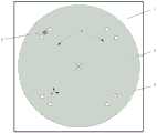
图3是根据本发明实施例的一种托盘机器人的托盘的示意图;3 is a schematic diagram of a pallet of a pallet robot according to an embodiment of the present invention;
图4是根据本发明实施例的一种托盘机器人的托盘位于归零位置的示意图;4 is a schematic diagram of a pallet of a pallet robot being located at a zero-returning position according to an embodiment of the present invention;
图5是根据本发明实施例的控制托盘转动的方法的主要步骤的示意图;5 is a schematic diagram of main steps of a method for controlling rotation of a tray according to an embodiment of the present invention;
图6是根据本发明实施例的控制托盘转动的方法的托盘转动过程中的位置示意图一;6 is a schematic diagram 1 of the position during the rotation of the tray in the method for controlling the rotation of the tray according to the embodiment of the present invention;
图7是根据本发明实施例的控制托盘转动的方法的托盘转动过程中的位置示意图二;FIG. 7 is a second position schematic diagram during the tray rotation process of the method for controlling tray rotation according to an embodiment of the present invention;
图8是根据本发明实施例的控制托盘转动的方法的托盘转动过程中的位置示意图三;8 is a schematic diagram 3 of the position during the rotation of the tray in the method for controlling the rotation of the tray according to the embodiment of the present invention;
图9是根据本发明实施例的控制托盘转动的方法的托盘转动过程中的位置示意图四;9 is a schematic diagram 4 of the position during the rotation of the tray in the method for controlling the rotation of the tray according to the embodiment of the present invention;
图10是根据本发明实施例的控制托盘转动的装置的主要模块的示意图;10 is a schematic diagram of the main modules of the device for controlling the rotation of the tray according to an embodiment of the present invention;
图11是本发明实施例可以应用于其中的示例性系统架构图;FIG. 11 is an exemplary system architecture diagram to which an embodiment of the present invention may be applied;
图12是适于用来实现本发明实施例的终端设备或服务器的计算机系统的结构示意图。FIG. 12 is a schematic structural diagram of a computer system suitable for implementing a terminal device or a server according to an embodiment of the present invention.
具体实施方式Detailed ways
以下结合附图对本发明的示范性实施例做出说明,其中包括本发明实施例的各种细节以助于理解,应当将它们认为仅仅是示范性的。因此,本领域普通技术人员应当认识到,可以对这里描述的实施例做出各种改变和修改,而不会背离本发明的范围和精神。同样,为了清楚和简明,以下的描述中省略了对公知功能和结构的描述。Exemplary embodiments of the present invention are described below with reference to the accompanying drawings, which include various details of the embodiments of the present invention to facilitate understanding and should be considered as exemplary only. Accordingly, those of ordinary skill in the art will recognize that various changes and modifications of the embodiments described herein can be made without departing from the scope and spirit of the invention. Also, descriptions of well-known functions and constructions are omitted from the following description for clarity and conciseness.
需要指出的是,在不冲突的情况下,本发明的实施例以及实施例中的技术特征可以相互结合。It should be pointed out that the embodiments of the present invention and the technical features in the embodiments may be combined with each other without conflict.
现有的托盘机器人所采用的托盘控制算法的流程如下:The process of the pallet control algorithm adopted by the existing pallet robot is as follows:
首先,托盘机器人接收到托盘旋转指令——托盘左转/右转角度(θ0);First, the pallet robot receives the pallet rotation instruction - the left/right rotation angle of the pallet (θ0);
其次,托盘机器人自动触发其上的货架二维码扫描器读取货架与车体的偏差角度(m),基于此计算托盘需要旋转的角度(θX):Secondly, the pallet robot automatically triggers the shelf QR code scanner on it to read the deviation angle (m) between the shelf and the car body, and calculate the angle (θX) that the pallet needs to rotate based on this:
托盘左转,θX=θ0-m;Turn the pallet to the left, θX=θ0-m;
托盘右转,θX=θ0+m;The pallet turns right, θX=θ0+m;
然后,根据托盘电机的实时码盘值(RealPlateNum)和上一个周期的码盘值(RealPlateNumOld),实时计算托盘剩余旋转角度(θY):Then, according to the real-time code plate value (RealPlateNum) of the pallet motor and the code plate value (RealPlateNumOld) of the previous cycle, the remaining rotation angle (θY) of the pallet is calculated in real time:
θY=θX-(RealPlateNum-RealPlateNumOld);θY=θX-(RealPlateNum-RealPlateNumOld);
最后,当θ2=0时,托盘到达特定位置,托盘电机停止动作。Finally, when θ2=0, the pallet reaches a specific position, and the pallet motor stops moving.
现有的托盘控制算法,仅凭借电机的码盘值估算位置,属于纯软件计算,不可避免存在的计算偏差,且没有消除偏差的机制,若长期使用就会存在累计偏差。并且为了保证货架与车体的相对位置无偏差,每次托盘转动均需要触发货架二维码扫描器的扫描、数据发送与接收以及数据解析与处理,对货架二维码扫描器的功能要求较高,器件选型难度与整车成本随之大幅提升,且增加了软硬件资源的消耗;货架与车体的相对位置偏差识别的准确度与货架二维码扫描器的可靠性相关联,而货架二维码扫描器的准确度与精度受自身技术与工作环境影响严重,仓库环境的多尘以及货架的抖动均影响货架二维码扫描器,降低了识别的准确度,货架二维码扫描器的可靠性低;货架二维码扫描器搭载在底盘上,可以识别货架与底盘(即车体)的相对位置偏差,而托盘与货架之间同样存在相对位置偏差,这是货架二维码扫描器无法识别的,也无法纠正和弥补,即存在算法控制盲区。The existing pallet control algorithm only estimates the position based on the code disc value of the motor, which belongs to pure software calculation, and there is inevitable calculation deviation, and there is no mechanism to eliminate the deviation. If it is used for a long time, there will be accumulated deviation. And in order to ensure that there is no deviation between the relative position of the shelf and the car body, each pallet rotation needs to trigger the scanning of the shelf QR code scanner, data transmission and reception, and data analysis and processing. The functional requirements of the shelf QR code scanner are relatively high. High, the difficulty of device selection and the cost of the whole vehicle have been greatly increased, and the consumption of software and hardware resources has increased; The accuracy and precision of the shelf QR code scanner are seriously affected by its own technology and working environment. The dusty warehouse environment and the shaking of the shelves all affect the shelf QR code scanner, which reduces the accuracy of identification. The reliability of the device is low; the shelf QR code scanner is mounted on the chassis, which can identify the relative position deviation between the shelf and the chassis (ie, the vehicle body), and there is also a relative position deviation between the pallet and the shelf. This is the shelf QR code. What the scanner cannot identify, and cannot correct or make up for, that is, there is an algorithm control blind spot.
为此,本发明实施例提出一种托盘机器人和控制托盘转动的方法,旨在消除底盘1与托盘2的位置偏差,即消除底盘1与托盘2之间的初始位置偏差、以及托盘2转动时增量编码器6估算位置引入的累计偏差,在不需要货架二维码识别货架位置偏差的同时,保证托盘2与货架的相对位置偏差可控可纠正,减少软硬件资源的消耗,提高托盘2转动的准确性和可靠性,同时降低托盘机器人的成本。To this end, the embodiment of the present invention proposes a pallet robot and a method for controlling the rotation of the pallet, aiming at eliminating the positional deviation between the
如图2-3所示,本发明实施例的一种托盘机器人,主要包括底盘1、托盘2、增量编码器6、零点限位开关3和控制部(图中并未示出)。其中,托盘2是托盘机器人的转动部件,用于带动其上的功能部件转动。在不便于整体转动的情况下,可以通过托盘2带动功能部件单独转动,例如叉车的托盘2用于带动货叉转动,以叉取货物;AGV的托盘2用于顶起货架转动,以将货架摆放为特定角度;图像采集机器人的托盘2用于带动照相机或摄像机转动,以调整镜头角度。增量编码器6是一种测量角位移的数字编码器,它具有分辨能力强、测量精度高和工作可靠等优点,是测量轴转角位置的一种最常用的位移传感器,增量编码器6能够利用计算系统将旋转码盘产生的脉冲增量针对某个基准数进行加减以求得角位移。本发明实施例中,增量编码器6用于检测托盘2的转动角度。零点限位开关3是一种机械装置,设置有机械零点感应标志位,机械零点感应标志位用于指示是否检测到该装置。本发明实施例中,当零点限位开关3与托盘2的零点孔5重合时,输入高电位,机械零点感应标志位的值为1;否则输入低电位,机械零点感应标志位的值为0。As shown in Figures 2-3, a pallet robot according to an embodiment of the present invention mainly includes a
具体地,增量编码器6设置于托盘2和底盘1之间,且增量编码器6位于托盘2的轴心。底盘1位于托盘2的下方,零点限位开关3设置于底盘1上,托盘2上设置有至少两组零点位4,其中,每组零点位4包括两个零点孔5,当零点限位开关3与任意一个零点孔5重合时,零点限位开关3输入高电位,否则输入低电位。控制部与增量编码器6和零点限位开关3通信连接,控制部用于控制托盘2的转动以及托盘机器人的运行等。控制部的零点标志位记录有在托盘2转动过程中零点限位开关3与零点孔5的重合次数以及托盘2的位置状态。此外,托盘机器人还包括使其正常运行并实现某些功能的其它部件,例如车轮、电机或扫描器等等,本发明实施例中不予赘述。Specifically, the
在本发明实施例中,零点位4沿托盘2的圆周均匀分布,零点限位开关3在托盘2上的投影位于零点孔5所在圆周。相邻的两个零点位4的中线的夹角可以称为零点相邻角,同一零点位4的两个零点孔5的圆心角可以称为零点内角,作为一种优选的实施方式,零点内角小于30°。此外,托盘2的形状可以是任意形状,例如圆形、方形或三角形等等。In the embodiment of the present invention, the zero
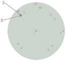
在本发明实施例中,还可以为托盘2设置归零位置,以该归零位置作为托盘2的理想初始位置,在托盘2完成一次托盘转动指令对应的动作后,再转动到该归零位置,以便于下一次接收到托盘转动指令时精准控制托盘2进行转动。当托盘2处于归零位置时,零点限位开关3位于其中一组零点位4的中线,例如图4中所示情形。In the embodiment of the present invention, a zero-returning position can also be set for the
在托盘2转动的过程中,托盘2相对底盘1上的零点限位开关3转动。当零点限位开关3与任意一个零点孔5重合时,零点限位开关3输入高电位,零点限位开关3的机械零点感应标志位的值为1,此时托盘2已转动到特定位置,通过识别该特定位置可以得到托盘2的位置状态,并得到托盘2从归零位置转动到特定位置已转过多少度,从而精准计算托盘2的剩余转动角度。否则(即零点限位开关3与任意一个零点孔5均不重合时),零点限位开关3输入低电位,零点限位开关3的机械零点感应标志位的值为0。控制部的零点标志位记录有,托盘2在执行一个托盘转动指令的转动过程(即托盘2转动到目标转动角度的过程)中,零点限位开关3与零点孔5的重合次数以及托盘2的位置状态,其中,托盘2的位置状态可以在检测到零点限位开关3与零点孔5重合时进行更新,也可以按预设频率进行更新。由于零点限位开关3和零点孔5的位置是固定的,所以,只要识别零点限位开关3与零点孔5的重合及重合次数,便可以在任意初始状态下修正托盘2的已转动角度和剩余转动角度,消除车体与托盘2之间的初始位置偏差,从而精准确定托盘2转动到的位置,并准确停车(即控制托盘2转动到特定位置后停止),避免停车位置与实际需求不一致。During the rotation of the
如图5所示,本发明实施例的控制托盘转动的方法主要包括以下步骤:As shown in FIG. 5 , the method for controlling the rotation of the tray according to the embodiment of the present invention mainly includes the following steps:
步骤S501:获取托盘2的目标转动角度。Step S501 : acquiring the target rotation angle of the
AGV、叉车和图像采集机器人等托盘机器人在运行时,通常受调度系统、控制中心或总服务器等控制,接受调度系统、控制中心或总服务器等的指令,并执行相应动作,在需要转动托盘2时,托盘机器人会接收到托盘转动指令,从托盘转动指令中可以获取到托盘2的目标转动角度。或,在需要使托盘2转动到特定位置时,预估需要转动的角度(即目标转动角度)。此外,可以通过目标转动角度的值的正负表示左转或右转,目标转动角度可以通过托盘机器人的控制部获取,并控制托盘2进行转动,还可以由第三方服务器代替控制部执行。When pallet robots such as AGVs, forklifts, and image acquisition robots are running, they are usually controlled by the dispatching system, control center or general server, etc., accept instructions from the dispatching system, control center or general server, etc., and perform corresponding actions. , the pallet robot will receive the pallet rotation instruction, and the target rotation angle of the
步骤S502:基于增量编码器6确定托盘2的已转动角度。Step S502 : Determine the rotated angle of the
增量编码器6能够利用计算系统将旋转码盘产生的脉冲增量针对某个基准数进行加减以求得角位移,即根据增量编码器6的数值可以确定托盘2的已转动角度。作为一种可选的实施方式,可以读取增量编码器6的当前周期的码盘值,并获取上一周期的码盘值(即执行完上一任务后托盘2停留位置对应的码盘值),用当前周期的码盘值减上一周期的码盘值即得到已转动角度。The
步骤S503:根据目标转动角度、已转动角度以及控制部的零点标志位,计算托盘2的剩余转动角度。Step S503 : Calculate the remaining rotation angle of the
由于托盘2安装到底盘1上的初始位置是人为摆正的,该初始位置与归零位置可能存在初始位置偏差,以及,在托盘2转动时增量编码器6估算位置也可能引入的累计偏差,根据零点标志位记载的内容,可以在计算剩余转动角度时纠正和弥补上述偏差,从而保证托盘2与货架的相对位置偏差可控可纠正,提高托盘2转动的准确性和可靠性;同时这一过程中不再需要货架二维码扫描器识别与货架的偏差,降低了托盘机器人的成本。Since the initial position of the
在本发明实施例中,步骤S503可以通过以下方式实现:根据目标转动角度和已转动角度计算托盘2的预测剩余角度;读取控制部的零点标志位,基于零点标志位修正预测剩余角度,得到托盘2的剩余转动角度。In the embodiment of the present invention, step S503 can be implemented in the following ways: calculating the predicted remaining angle of the
用托盘2的目标转动角度减托盘2的已转动角度即可得到托盘2的预测剩余角度,该预测剩余角度是基于已转动角度所估算的托盘2还需要转多少度可以转到特定位置,但已转动角度是根据从增量编码器6中读取的数值所得到的托盘2实际转过多少度,而不是以归零位置为基准转过多少度,所以需要根据零点标志位的内容对该预测剩余角度进行修正,以准确得到托盘2的剩余转动角度。The predicted remaining angle of
在本发明实施例中,读取控制部的零点标志位,基于零点标志位修正预测剩余角度,得到托盘2的剩余转动角度,这一步骤可以通过以下方式实现:读取控制部的零点标志位,得到重合次数和托盘2的位置状态;根据重合次数和已转动角度修正预测剩余角度,得到托盘2的剩余转动角度,并更新托盘2的位置状态以及目标转动角度;或根据重合次数和托盘2的位置状态修正托盘2的预测剩余角度,得到托盘2的剩余转动角度,并更新托盘2的位置状态以及目标转动角度。In the embodiment of the present invention, the zero mark position of the control part is read, the predicted remaining angle is corrected based on the zero mark position, and the remaining rotation angle of the
在托盘2转动的过程中,当零点限位开关3与任意一个零点孔5重合时,零点限位开关3输入高电位,零点限位开关3的机械零点感应标志位的值为1,此时托盘2已转动到特定位置,通过识别该特定位置可以得到托盘2从归零位置转动到特定位置已转过多少度,从而修正托盘2的预测剩余角度得到托盘2的剩余转动角度,同时,根据该特定位置还可以更新托盘2的位置状态;当零点限位开关3与任意一个零点孔5均不重合时,零点限位开关3输入低电位,零点限位开关3的机械零点感应标志位的值为0。在控制托盘2转动到目标转动角度的全部过程(即托盘2在执行一个托盘转动指令的转动过程)中,零点限位开关3与零点孔5的重合次数以及托盘2的位置状态均记录在控制部的零点标志位,在计算托盘2的剩余转动角度时,可以根据重合次数和已转动角度进行计算,也可以根据重合次数、已转动角度和托盘2的位置状态进行计算。During the rotation of the
需要说明的是,在控制托盘2转动到目标转动角度的全部过程中,可能存在多次计算更新剩余转动角度,即在每次检测到零点限位开关3与零点孔5重合时,计算托盘2的剩余转动角度,并对托盘2的位置状态进行更新,每次计算前重新读取已转动角度,且每次计算后目标转动角度的数值也会进行更新,更新后的目标转动角度表示理论上托盘2转动到特定位置还需要转动的角度。It should be noted that, in the whole process of controlling the rotation of the
在本发明实施例中,根据重合次数和已转动角度修正预测剩余角度,得到托盘2的剩余转动角度,并更新托盘2的位置状态以及目标转动角度,这一步骤可以具体通过以下方式实现:若重合次数为0,则θ2=θ1-θOK,将目标转动角度的值更新为剩余转动角度的值;若重合次数为1,则获取已转动角度,当已转动角度大于零点相邻角的一半时,θ2=θ1-(a-b/2),将托盘2的位置状态更新为第一状态,将目标转动角度的值更新为剩余转动角度的值;当已转动角度小于或等于零点相邻角的一半时,θ2=θ1-(b/2),将托盘2的位置状态更新为第二状态,将目标转动角度的值更新为剩余转动角度的值。In the embodiment of the present invention, the predicted remaining angle is corrected according to the number of overlaps and the rotated angle to obtain the remaining rotation angle of the
在本发明实施例中,根据重合次数和托盘2的位置状态修正托盘2的预测剩余角度,得到托盘2的剩余转动角度,并更新托盘2的位置状态以及目标转动角度,这一步骤可以具体通过以下方式实现:若重合次数大于或等于2,则获取最新两次重合对应的零点孔5的圆心角,当最新两次重合对应的零点孔5的圆心角大于零点内角时,θ2=θ1-(a-b),将托盘2的位置状态更新为第五状态,将目标转动角度的值更新为剩余转动角度的值;当最新两次重合对应的零点孔5的圆心角等于零点内角时,查询托盘2的位置状态,如果托盘2的位置状态为第二状态,θ2=θ1,将托盘2的位置状态更新为第四状态,将目标转动角度的值更新为剩余转动角度的值,如果托盘2的位置状态为第一状态、第二状态、第三状态或第五状态,θ2=θ1-b,将托盘2的位置状态更新为第三状态,将目标转动角度的值更新为剩余转动角度的值。In the embodiment of the present invention, the predicted remaining angle of the
其中,θ2是剩余转动角度;θ1是目标转动角度;θOK是已转动角度;a是零点相邻角,零点相邻角是相邻的两个零点位4的中线的夹角;b是零点内角,零点内角是同一零点位4的两个零点孔5的圆心角。Among them, θ2 is the remaining rotation angle; θ1 is the target rotation angle; θOK is the rotated angle; a is the adjacent angle of the zero point, and the adjacent angle of the zero point is the angle between the center lines of two adjacent zero points; b is the inner angle of the zero point , the inner angle of the zero point is the central angle of the two zero
当零点限位开关3与零点孔5的重合次数为0时,无法进行修正,可以直接用目标转动角度减已转动角度来计算剩余转动角度。When the number of coincidences between the zero
当零点限位开关3与零点孔5的重合次数为1时,托盘2相对归零位置转过的角度大于零点内角的一半、但小于零点相邻角减零点内角,若已转动角度大于零点相邻角的一半,则表示托盘2转动的起始位置不是归零位置,托盘2转动的过程是其上的一个零点位4从远离到靠近零点限位开关3,否则表示托盘2转动的起始位置是归零位置,托盘2转动的过程是其上的一个零点位4一直靠近零点限位开关3(托盘2的一个零点位4之内的区域从零点限位开关3上转过),因此,可以结合已转动角度进行修正。When the number of coincidences between the zero
当零点限位开关3与零点孔5的重合次数大于或等于2时,托盘2相对归零位置转过的角度大于或等于零点内角、但小于零点相邻角加零点内角的一半,若最新两次重合对应的零点孔5的圆心角等于零点内角,则表示托盘2转动的过程是其上的一个零点位4完整地从零点限位开关3上转过,若最新两次重合对应的零点孔5的圆心角大于零点内角,则表示托盘2转动的过程可能是分别属于相邻的两个零点位4的零点孔5依次从零点限位开关3上转过、或托盘2转动的起始位置不是归零位置导致托盘2转动的角度大于理论值,因此,可以结合托盘2的位置状态进行修正。When the number of coincidences between the zero
基于上述算法,可以在任意初始状态下修正托盘2的已转动角度和剩余转动角度,消除车体与托盘2之间的初始位置偏差,从而精准确定托盘2转动到的位置,并准确停车(即控制托盘2转动到特定位置后停止),避免停车位置与实际需求不一致。Based on the above algorithm, the rotated angle and the remaining rotation angle of the
在本发明实施例中,控制托盘转动的方法还可以包括:控制托盘2转动到归零位置。In the embodiment of the present invention, the method for controlling the rotation of the tray may further include: controlling the rotation of the
该归零位置作为托盘2的理想初始位置,在托盘2完成一次托盘转动指令对应的动作后,再转动到该归零位置,以便于下一次接收到托盘转动指令时精准控制托盘2进行转动。此外,可以为归零位置对应的零点位4设置与其它零点位4不同的零点内角,例如归零位置对应的零点位4的零点内角为8°、其它零点位4的零点内角为10°,通过零点内角来控制托盘2转到归零位置;也可以控制托盘2反向转回到归零位置等等。The zero-return position is used as the ideal initial position of the
根据本发明实施例的控制托盘转动的方法可以看出,因为采用获取托盘2的目标转动角度;基于增量编码器6确定托盘2的已转动角度;根据目标转动角度、已转动角度以及控制部的零点标志位,计算托盘2的剩余转动角度的技术手段,所以克服了货架二维码扫描器无法识别托盘与货架之间的相对位置偏差,且现有托盘控制算法无法纠正和弥补,存在算法控制盲区;货架二维码扫描器的准确度和可靠性较低;以及对货架二维码扫描器的功能要求较高,且数据采集、发送、解析和处理等消耗的软硬件资源较多的技术问题,进而达到在不需要货架二维码识别货架位置偏差的同时,保证托盘2与货架的相对位置偏差可控可纠正,减少软硬件资源的消耗;提高托盘2转动的准确性和可靠性,同时降低托盘机器人成本的技术效果。According to the method for controlling the rotation of the tray according to the embodiment of the present invention, it can be seen that the target rotation angle of the
为了进一步阐述本发明的技术思想,现结合具体的应用场景,对本发明的技术方案进行说明。In order to further illustrate the technical idea of the present invention, the technical solutions of the present invention are now described with reference to specific application scenarios.
假设某AGV的托盘2设置有四组零点位4,零点内角为10°,零点相邻角为90°,在控制托盘2转动的过程中,每次检测到机械零点(即零点限位开关3与零点孔5重合)时,itsInZeroFlag=1,其它情况itsInZeroFlag=0,检测到机械零点的次数itsInZeroNum(即重合次数)记录在控制部的零点标志位,该零点标志位还记录有托盘2的位置状态(palletstatus)。则控制托盘转动的方法应用于该AGV的主要流程如下:Assuming that the
首先,托盘机器人接收到托盘转动指令,该托盘转动指令中携带有需要托盘2左转或右转的角度(即θ1);First, the pallet robot receives a pallet rotation instruction, and the pallet rotation instruction carries an angle (ie, θ1) that requires the
然后,读取增量编码器6的当前周期的码盘值,并获取上一周期的码盘值,用当前周期的码盘值减上一周期的码盘值即得到θOK;Then, read the code wheel value of the current cycle of the
最后,在控制托盘转动的过程中,根据θ1、θOK、机械零点感应标志位(itsInZeroFlag)、最新两次重合对应的零点孔5的圆心角(θZero)、零点限位开关3与零点孔5的重合次数和托盘2的位置状态,可以实时计算托盘2的θ2,直至θ2=0°(此时托盘2转动到托盘转动指令对应的特定位置),控制托盘2停止转动。具体如下:Finally, in the process of controlling the rotation of the pallet, according to θ1, θOK, the mechanical zero point induction flag (itsInZeroFlag), the center angle (θZero) of the zero
1.未检测到机械零点时:1. When the mechanical zero point is not detected:
重合次数为0,则θ2=θ1-θOK,此时更新目标转动角度,即θ1=θ1-θOK;The number of coincidences is 0, then θ2=θ1-θOK, and the target rotation angle is updated at this time, that is, θ1=θ1-θOK;
2.第一次检测到机械零点时:2. When the mechanical zero point is detected for the first time:
重合次数为1,此时itsInZeroFlag=1、itsInZeroNum=1;The number of coincidences is 1, at this time itsInZeroFlag=1, itsInZeroNum=1;
如果θOK(α1)>45°:If θOK(α1)>45°:
则θ2=θ1–85°,此时更新目标转动角度,即θ1=θ1–85°,并将托盘2的位置状态更新为第一状态,即palletstatus=1(如图6所示位置);Then θ2=θ1-85°, at this time, the target rotation angle is updated, that is, θ1=θ1-85°, and the position state of
如果θOK(α1)≤45°:If θOK(α1)≤45°:
则θ2=θ1–5°,此时更新目标转动角度,即θ1=θ1–5°,并将托盘2的位置状态更新为第二状态,即palletstatus=2(如图7、8和9所示位置,其中图9所示的托盘2的定位还需要进一步确认);Then θ2=θ1-5°, at this time, update the target rotation angle, that is, θ1=θ1-5°, and update the position state of
3.第二次及以上检测到机械零点时:3. When the mechanical zero point is detected for the second time and above:
重合次数大于或等于2,此时itsInZeroFlag=1、itsInZeroNum≥2;The number of coincidences is greater than or equal to 2, at this time itsInZeroFlag=1, itsInZeroNum≥2;
如果托盘转过的角度θZero(α2)>10°:If the angle θZero(α2) is turned by the tray > 10°:
则θ2=θ1–80°,此时更新目标转动角度,即θ1=θ1–80°,并将托盘2的位置状态更新为第五状态,即palletstatus=5(如图7和8所示位置);Then θ2=θ1-80°, at this time, the target rotation angle is updated, that is, θ1=θ1-80°, and the position status of
如果托盘转过的角度θZero(α2)=10°:If the angle θZero(α2) = 10° by which the tray is turned:
若palletstatus=2,θ2=θ1,此时θ1不更新,将托盘2的位置状态更新为第四状态,即palletstatus=4(如图9所示位置,较正算法中托盘2的位置);If palletstatus=2, θ2=θ1, θ1 is not updated at this time, and the position state of
若palletstatus≠2,θ2=θ1–10°,此时更新目标转动角度,即θ1=θ1–10°,并将托盘2的位置状态更新为第三状态,即palletstatus=3(如图6所示位置)。If
如图10所示,本发明实施例的控制托盘转动的装置1000包括:获取模块1001、确定模块1002和计算模块1003。As shown in FIG. 10 , the
其中,in,
获取模块1001,用于获取托盘2的目标转动角度;An
确定模块1002,用于基于增量编码器6确定托盘2的已转动角度;A
计算模块1003,用于根据目标转动角度、已转动角度以及控制部的零点标志位,计算托盘2的剩余转动角度。The
在本发明实施例中,计算模块1003还可以用于:In this embodiment of the present invention, the
根据目标转动角度和已转动角度计算托盘2的预测剩余角度;Calculate the predicted remaining angle of the
读取控制部的零点标志位,基于零点标志位修正预测剩余角度,得到托盘2的剩余转动角度。The zero-point flag of the control unit is read, and the predicted remaining angle is corrected based on the zero-point flag to obtain the remaining rotation angle of the
在本发明实施例中,计算模块1003可以进一步用于:In this embodiment of the present invention, the
读取控制部的零点标志位,得到重合次数和托盘2的位置状态;Read the zero mark position of the control part to obtain the number of overlaps and the position status of the
根据重合次数和已转动角度修正预测剩余角度,得到托盘2的剩余转动角度,并更新托盘2的位置状态以及目标转动角度;或Correct the predicted remaining angle according to the number of overlaps and the rotated angle, obtain the remaining rotation angle of the
根据重合次数和托盘2的位置状态修正托盘2的预测剩余角度,得到托盘2的剩余转动角度,并更新托盘2的位置状态以及目标转动角度。Correct the predicted remaining angle of the
在本发明实施例中,计算模块1003可以进一步用于:In this embodiment of the present invention, the
若重合次数为0,则θ2=θ1-θOK,将目标转动角度的值更新为剩余转动角度的值;If the number of coincidence times is 0, then θ2=θ1-θOK, and the value of the target rotation angle is updated to the value of the remaining rotation angle;
若重合次数为1,则获取已转动角度,If the number of coincidences is 1, the rotated angle is obtained,
当已转动角度大于零点相邻角的一半时,θ2=θ1-(a-b/2),将托盘2的位置状态更新为第一状态,将目标转动角度的值更新为剩余转动角度的值;When the rotated angle is greater than half of the adjacent angle at the zero point, θ2=θ1-(a-b/2), update the position state of the
当已转动角度小于或等于零点相邻角的一半时,θ2=θ1-(b/2),将托盘2的位置状态更新为第二状态,将目标转动角度的值更新为剩余转动角度的值;When the rotated angle is less than or equal to half of the adjacent angle of the zero point, θ2=θ1-(b/2), update the position state of
其中,θ2是剩余转动角度;θ1是目标转动角度;θOK是已转动角度;a是零点相邻角,零点相邻角是相邻的两个零点位4的中线的夹角;b是零点内角,零点内角是同一零点位4的两个零点孔5的圆心角。Among them, θ2 is the remaining rotation angle; θ1 is the target rotation angle; θOK is the rotated angle; a is the adjacent angle of the zero point, and the adjacent angle of the zero point is the angle between the center lines of two adjacent zero points; b is the inner angle of the zero point , the inner angle of the zero point is the central angle of the two zero
在本发明实施例中,计算模块1003可以进一步用于:In this embodiment of the present invention, the
若重合次数大于或等于2,则获取最新两次重合对应的零点孔5的圆心角,If the number of coincidences is greater than or equal to 2, obtain the central angle of the zero
当最新两次重合对应的零点孔5的圆心角大于零点内角时,θ2=θ1-(a-b),将托盘2的位置状态更新为第五状态,将目标转动角度的值更新为剩余转动角度的值;When the central angle of the zero
当最新两次重合对应的零点孔5的圆心角等于零点内角时,查询托盘2的位置状态,When the central angle of the zero
如果托盘2的位置状态为第二状态,θ2=θ1,将托盘2的位置状态更新为第四状态,将目标转动角度的值更新为剩余转动角度的值,If the position state of
如果托盘2的位置状态为第一状态、第二状态、第三状态或第五状态,θ2=θ1-b,将托盘2的位置状态更新为第三状态,将目标转动角度的值更新为剩余转动角度的值。If the position state of the
此外,控制托盘转动的装置1000还可以包括控制模块(图中并未示出),用于:控制托盘2转动到归零位置;其中,所述归零位置为所述托盘2处于所述零点限位开关3位于其中一组所述零点位4的中线的位置。In addition, the
根据本发明实施例的控制托盘转动的装置可以看出,因为采用获取托盘2的目标转动角度;基于增量编码器6确定托盘2的已转动角度;根据目标转动角度、已转动角度以及控制部的零点标志位,计算托盘2的剩余转动角度的技术手段,所以克服了货架二维码扫描器无法识别托盘与货架之间的相对位置偏差,且现有托盘控制算法无法纠正和弥补,存在算法控制盲区;货架二维码扫描器的准确度和可靠性较低;以及对货架二维码扫描器的功能要求较高,且数据采集、发送、解析和处理等消耗的软硬件资源较多的技术问题,进而达到在不需要货架二维码识别货架位置偏差的同时,保证托盘2与货架的相对位置偏差可控可纠正,减少软硬件资源的消耗;提高托盘2转动的准确性和可靠性,同时降低托盘机器人成本的技术效果。According to the device for controlling the rotation of the tray according to the embodiment of the present invention, it can be seen that, because the target rotation angle of the
图11示出了可以应用本发明实施例的控制托盘转动的方法或控制托盘转动的装置的示例性系统架构1100。FIG. 11 shows an
如图11所示,系统架构1100可以包括终端设备1101、1102、1103,网络1104和服务器1105。网络1104用以在终端设备1101、1102、1103和服务器1105之间提供通信链路的介质。网络1104可以包括各种连接类型,例如有线、无线通信链路或者光纤电缆等等。As shown in FIG. 11 , the
用户可以使用终端设备1101、1102、1103通过网络1104与服务器1105交互,以接收或发送消息等。终端设备1101、1102、1103上可以安装有各种通讯客户端应用,例如购物类应用、网页浏览器应用、搜索类应用、即时通信工具、邮箱客户端、社交平台软件等。The user can use the
终端设备1101、1102、1103可以是具有显示屏并且支持网页浏览的各种电子设备,包括但不限于智能手机、平板电脑、膝上型便携计算机和台式计算机等等。The
服务器1105可以是提供各种服务的服务器,例如对用户利用终端设备1101、1102、1103所浏览的购物类网站提供支持的后台管理服务器。后台管理服务器可以对接收到的产品信息查询请求等数据进行分析等处理,并将处理结果(例如目标推送信息、产品信息)反馈给终端设备。The
需要说明的是,本发明实施例所提供的控制托盘转动的方法一般由服务器1105执行,相应地,控制托盘转动的装置一般设置于服务器1105中。It should be noted that the method for controlling the rotation of the tray provided by the embodiment of the present invention is generally performed by the
应该理解,图11中的终端设备、网络和服务器的数目仅仅是示意性的。根据实现需要,可以具有任意数目的终端设备、网络和服务器。It should be understood that the numbers of terminal devices, networks and servers in FIG. 11 are merely illustrative. There can be any number of terminal devices, networks and servers according to implementation needs.
下面参考图12,其示出了适于用来实现本发明实施例的终端设备的计算机系统1200的结构示意图。图12示出的终端设备仅仅是一个示例,不应对本发明实施例的功能和使用范围带来任何限制。Referring to FIG. 12 below, it shows a schematic structural diagram of a
如图12所示,计算机系统1200包括中央处理单元(CPU)1201,其可以根据存储在只读存储器(ROM)1202中的程序或者从存储部分1208加载到随机访问存储器(RAM)1203中的程序而执行各种适当的动作和处理。在RAM 1203中,还存储有系统1200操作所需的各种程序和数据。CPU 1201、ROM 1202以及RAM 1203通过总线1204彼此相连。输入/输出(I/O)接口1205也连接至总线1204。As shown in FIG. 12, a
以下部件连接至I/O接口1205:包括键盘、鼠标等的输入部分1206;包括诸如阴极射线管(CRT)、液晶显示器(LCD)等以及扬声器等的输出部分1207;包括硬盘等的存储部分1208;以及包括诸如LAN卡、调制解调器等的网络接口卡的通信部分1209。通信部分1209经由诸如因特网的网络执行通信处理。驱动器1210也根据需要连接至I/O接口1205。可拆卸介质1211,诸如磁盘、光盘、磁光盘、半导体存储器等等,根据需要安装在驱动器1210上,以便于从其上读出的计算机程序根据需要被安装入存储部分1208。The following components are connected to the I/O interface 1205: an
特别地,根据本发明公开的实施例,上文参考流程图描述的过程可以被实现为计算机软件程序。例如,本发明公开的实施例包括一种计算机程序产品,其包括承载在计算机可读介质上的计算机程序,该计算机程序包含用于执行流程图所示的方法的程序代码。在这样的实施例中,该计算机程序可以通过通信部分1209从网络上被下载和安装,和/或从可拆卸介质1211被安装。在该计算机程序被中央处理单元(CPU)1201执行时,执行本发明的系统中限定的上述功能。In particular, the processes described above with reference to the flowcharts may be implemented as computer software programs in accordance with the disclosed embodiments of the present invention. For example, embodiments disclosed herein include a computer program product comprising a computer program carried on a computer-readable medium, the computer program containing program code for performing the method illustrated in the flowchart. In such an embodiment, the computer program may be downloaded and installed from the network via the
需要说明的是,本发明所示的计算机可读介质可以是计算机可读信号介质或者计算机可读存储介质或者是上述两者的任意组合。计算机可读存储介质例如可以是——但不限于——电、磁、光、电磁、红外线、或半导体的系统、装置或器件,或者任意以上的组合。计算机可读存储介质的更具体的例子可以包括但不限于:具有一个或多个导线的电连接、便携式计算机磁盘、硬盘、随机访问存储器(RAM)、只读存储器(ROM)、可擦式可编程只读存储器(EPROM或闪存)、光纤、便携式紧凑磁盘只读存储器(CD-ROM)、光存储器件、磁存储器件、或者上述的任意合适的组合。在本发明中,计算机可读存储介质可以是任何包含或存储程序的有形介质,该程序可以被指令执行系统、装置或者器件使用或者与其结合使用。而在本发明中,计算机可读的信号介质可以包括在基带中或者作为载波一部分传播的数据信号,其中承载了计算机可读的程序代码。这种传播的数据信号可以采用多种形式,包括但不限于电磁信号、光信号或上述的任意合适的组合。计算机可读的信号介质还可以是计算机可读存储介质以外的任何计算机可读介质,该计算机可读介质可以发送、传播或者传输用于由指令执行系统、装置或者器件使用或者与其结合使用的程序。计算机可读介质上包含的程序代码可以用任何适当的介质传输,包括但不限于:无线、电线、光缆、RF等等,或者上述的任意合适的组合。It should be noted that the computer-readable medium shown in the present invention may be a computer-readable signal medium or a computer-readable storage medium, or any combination of the above two. The computer-readable storage medium can be, for example, but not limited to, an electrical, magnetic, optical, electromagnetic, infrared, or semiconductor system, apparatus or device, or a combination of any of the above. More specific examples of computer readable storage media may include, but are not limited to, electrical connections with one or more wires, portable computer disks, hard disks, random access memory (RAM), read only memory (ROM), erasable Programmable read only memory (EPROM or flash memory), fiber optics, portable compact disk read only memory (CD-ROM), optical storage devices, magnetic storage devices, or any suitable combination of the foregoing. In the present invention, a computer-readable storage medium may be any tangible medium that contains or stores a program that can be used by or in conjunction with an instruction execution system, apparatus, or device. In the present invention, however, a computer-readable signal medium may include a data signal propagated in baseband or as part of a carrier wave, carrying computer-readable program code therein. Such propagated data signals may take a variety of forms, including but not limited to electromagnetic signals, optical signals, or any suitable combination of the foregoing. A computer-readable signal medium can also be any computer-readable medium other than a computer-readable storage medium that can transmit, propagate, or transport the program for use by or in connection with the instruction execution system, apparatus, or device . Program code embodied on a computer readable medium may be transmitted using any suitable medium including, but not limited to, wireless, wireline, optical fiber cable, RF, etc., or any suitable combination of the foregoing.
附图中的流程图和框图,图示了按照本发明各种实施例的系统、方法和计算机程序产品的可能实现的体系架构、功能和操作。在这点上,流程图或框图中的每个方框可以代表一个模块、程序段、或代码的一部分,上述模块、程序段、或代码的一部分包含一个或多个用于实现规定的逻辑功能的可执行指令。也应当注意,在有些作为替换的实现中,方框中所标注的功能也可以以不同于附图中所标注的顺序发生。例如,两个接连地表示的方框实际上可以基本并行地执行,它们有时也可以按相反的顺序执行,这依所涉及的功能而定。也要注意的是,框图或流程图中的每个方框、以及框图或流程图中的方框的组合,可以用执行规定的功能或操作的专用的基于硬件的系统来实现,或者可以用专用硬件与计算机指令的组合来实现。The flowchart and block diagrams in the Figures illustrate the architecture, functionality, and operation of possible implementations of systems, methods and computer program products according to various embodiments of the present invention. In this regard, each block in the flowchart or block diagrams may represent a module, segment, or portion of code that contains one or more logical functions for implementing the specified functions executable instructions. It should also be noted that, in some alternative implementations, the functions noted in the blocks may occur out of the order noted in the figures. For example, two blocks shown in succession may, in fact, be executed substantially concurrently, or the blocks may sometimes be executed in the reverse order, depending upon the functionality involved. It is also noted that each block of the block diagrams or flowchart illustrations, and combinations of blocks in the block diagrams or flowchart illustrations, can be implemented in special purpose hardware-based systems that perform the specified functions or operations, or can be implemented using A combination of dedicated hardware and computer instructions is implemented.
描述于本发明实施例中所涉及到的模块可以通过软件的方式实现,也可以通过硬件的方式来实现。所描述的模块也可以设置在处理器中,例如,可以描述为:一种处理器包括获取模块、确定模块和计算模块。其中,这些模块的名称在某种情况下并不构成对该模块本身的限定,例如,获取模块还可以被描述为“获取托盘2的目标转动角度的模块”。The modules involved in the embodiments of the present invention may be implemented in a software manner, and may also be implemented in a hardware manner. The described modules can also be provided in the processor, for example, it can be described as: a processor includes an acquisition module, a determination module and a calculation module. Wherein, the names of these modules do not constitute a limitation of the module itself in some cases, for example, the acquisition module can also be described as "a module for acquiring the target rotation angle of the
作为另一方面,本发明还提供了一种计算机可读介质,该计算机可读介质可以是上述实施例中描述的设备中所包含的;也可以是单独存在,而未装配入该设备中。上述计算机可读介质承载有一个或者多个程序,当上述一个或者多个程序被一个该设备执行时,使得该设备包括:步骤S501:获取托盘2的目标转动角度;步骤S502:基于增量编码器6确定托盘2的已转动角度;步骤S503:根据目标转动角度、已转动角度以及控制部的零点标志位,计算托盘2的剩余转动角度。As another aspect, the present invention also provides a computer-readable medium, which may be included in the device described in the above embodiments; or may exist alone without being assembled into the device. The above-mentioned computer-readable medium carries one or more programs, and when the above-mentioned one or more programs are executed by a device, the device includes: step S501: acquiring the target rotation angle of the
根据本发明实施例的技术方案,因为采用获取托盘2的目标转动角度;基于增量编码器6确定托盘2的已转动角度;根据目标转动角度、已转动角度以及控制部的零点标志位,计算托盘2的剩余转动角度的技术手段,所以克服了货架二维码扫描器无法识别托盘与货架之间的相对位置偏差,且现有托盘控制算法无法纠正和弥补,存在算法控制盲区;货架二维码扫描器的准确度和可靠性较低;以及对货架二维码扫描器的功能要求较高,且数据采集、发送、解析和处理等消耗的软硬件资源较多的技术问题,进而达到在不需要货架二维码识别货架位置偏差的同时,保证托盘2与货架的相对位置偏差可控可纠正,减少软硬件资源的消耗;提高托盘2转动的准确性和可靠性,同时降低托盘机器人成本的技术效果。According to the technical solution of the embodiment of the present invention, because the target rotation angle of the
上述具体实施方式,并不构成对本发明保护范围的限制。本领域技术人员应该明白的是,取决于设计要求和其他因素,可以发生各种各样的修改、组合、子组合和替代。任何在本发明的精神和原则之内所作的修改、等同替换和改进等,均应包含在本发明保护范围之内。The above-mentioned specific embodiments do not constitute a limitation on the protection scope of the present invention. It should be understood by those skilled in the art that various modifications, combinations, sub-combinations and substitutions may occur depending on design requirements and other factors. Any modifications, equivalent replacements and improvements made within the spirit and principle of the present invention shall be included within the protection scope of the present invention.
Claims (9)
Translated fromChinesePriority Applications (1)
| Application Number | Priority Date | Filing Date | Title |
|---|---|---|---|
| CN201910864695.0ACN112478540B (en) | 2019-09-12 | 2019-09-12 | Method and device for controlling rotation of tray |
Applications Claiming Priority (1)
| Application Number | Priority Date | Filing Date | Title |
|---|---|---|---|
| CN201910864695.0ACN112478540B (en) | 2019-09-12 | 2019-09-12 | Method and device for controlling rotation of tray |
Publications (2)
| Publication Number | Publication Date |
|---|---|
| CN112478540Atrue CN112478540A (en) | 2021-03-12 |
| CN112478540B CN112478540B (en) | 2023-05-02 |
Family
ID=74920803
Family Applications (1)
| Application Number | Title | Priority Date | Filing Date |
|---|---|---|---|
| CN201910864695.0AActiveCN112478540B (en) | 2019-09-12 | 2019-09-12 | Method and device for controlling rotation of tray |
Country Status (1)
| Country | Link |
|---|---|
| CN (1) | CN112478540B (en) |
Cited By (3)
| Publication number | Priority date | Publication date | Assignee | Title |
|---|---|---|---|---|
| CN113137940A (en)* | 2021-04-23 | 2021-07-20 | 歌尔股份有限公司 | Control method, device and equipment of electronic equipment and readable storage medium |
| CN114013953A (en)* | 2021-11-02 | 2022-02-08 | 湖南省烟草公司衡阳市公司 | Method and system for positioning position of tray of elevator and computer storage medium |
| CN117381804A (en)* | 2023-12-13 | 2024-01-12 | 珠海格力智能装备有限公司 | Automatic material placement part aligning method and device for intelligent transfer robot |
Citations (10)
| Publication number | Priority date | Publication date | Assignee | Title |
|---|---|---|---|---|
| JPH01108740A (en)* | 1987-10-21 | 1989-04-26 | Fuji Electric Co Ltd | Transfer positioning system for semiconductor wafer |
| US20130180953A1 (en)* | 2011-04-13 | 2013-07-18 | Tetsuhiro Iwai | Plasma processing apparatus and plasma processing method |
| CN104425328A (en)* | 2013-09-06 | 2015-03-18 | 北京北方微电子基地设备工艺研究中心有限责任公司 | Tray origin positioning system and tray origin positioning method |
| CN104443977A (en)* | 2014-09-23 | 2015-03-25 | 华北电力大学 | Rotary type automatic goods storing and taking device and method |
| CN105314344A (en)* | 2014-07-16 | 2016-02-10 | 加特可株式会社 | Rotating device for tray |
| CN106516591A (en)* | 2016-11-22 | 2017-03-22 | 首钢京唐钢铁联合有限责任公司 | Rotation control method and rotation control device for conveying chain rotating platform |
| CN109230475A (en)* | 2017-07-11 | 2019-01-18 | 浙江国自机器人技术有限公司 | Pallet deviation correction method and device |
| CN110002367A (en)* | 2019-03-28 | 2019-07-12 | 上海快仓智能科技有限公司 | AGV form regulation system and method during AGV Transport cargo rack |
| CN110153994A (en)* | 2018-02-16 | 2019-08-23 | 日本电产三协株式会社 | The amendment value calculating method of industrial robot |
| CN110160566A (en)* | 2018-02-15 | 2019-08-23 | 精工爱普生株式会社 | Cell encoder, angle detecting method and robot |
- 2019
- 2019-09-12CNCN201910864695.0Apatent/CN112478540B/enactiveActive
Patent Citations (10)
| Publication number | Priority date | Publication date | Assignee | Title |
|---|---|---|---|---|
| JPH01108740A (en)* | 1987-10-21 | 1989-04-26 | Fuji Electric Co Ltd | Transfer positioning system for semiconductor wafer |
| US20130180953A1 (en)* | 2011-04-13 | 2013-07-18 | Tetsuhiro Iwai | Plasma processing apparatus and plasma processing method |
| CN104425328A (en)* | 2013-09-06 | 2015-03-18 | 北京北方微电子基地设备工艺研究中心有限责任公司 | Tray origin positioning system and tray origin positioning method |
| CN105314344A (en)* | 2014-07-16 | 2016-02-10 | 加特可株式会社 | Rotating device for tray |
| CN104443977A (en)* | 2014-09-23 | 2015-03-25 | 华北电力大学 | Rotary type automatic goods storing and taking device and method |
| CN106516591A (en)* | 2016-11-22 | 2017-03-22 | 首钢京唐钢铁联合有限责任公司 | Rotation control method and rotation control device for conveying chain rotating platform |
| CN109230475A (en)* | 2017-07-11 | 2019-01-18 | 浙江国自机器人技术有限公司 | Pallet deviation correction method and device |
| CN110160566A (en)* | 2018-02-15 | 2019-08-23 | 精工爱普生株式会社 | Cell encoder, angle detecting method and robot |
| CN110153994A (en)* | 2018-02-16 | 2019-08-23 | 日本电产三协株式会社 | The amendment value calculating method of industrial robot |
| CN110002367A (en)* | 2019-03-28 | 2019-07-12 | 上海快仓智能科技有限公司 | AGV form regulation system and method during AGV Transport cargo rack |
Cited By (4)
| Publication number | Priority date | Publication date | Assignee | Title |
|---|---|---|---|---|
| CN113137940A (en)* | 2021-04-23 | 2021-07-20 | 歌尔股份有限公司 | Control method, device and equipment of electronic equipment and readable storage medium |
| CN114013953A (en)* | 2021-11-02 | 2022-02-08 | 湖南省烟草公司衡阳市公司 | Method and system for positioning position of tray of elevator and computer storage medium |
| CN117381804A (en)* | 2023-12-13 | 2024-01-12 | 珠海格力智能装备有限公司 | Automatic material placement part aligning method and device for intelligent transfer robot |
| CN117381804B (en)* | 2023-12-13 | 2024-04-02 | 珠海格力智能装备有限公司 | Automatic material placement part aligning method and device for intelligent transfer robot |
Also Published As
| Publication number | Publication date |
|---|---|
| CN112478540B (en) | 2023-05-02 |
Similar Documents
| Publication | Publication Date | Title |
|---|---|---|
| CN112478540B (en) | Method and device for controlling rotation of tray | |
| CN111209978B (en) | Three-dimensional visual repositioning method and device, computing equipment and storage medium | |
| US9736024B2 (en) | Registering devices for network access | |
| WO2019154443A2 (en) | Navigation control method, smart warehousing system, and automated guided vehicle | |
| Olson | Robust and efficient robotic mapping | |
| CN110379044B (en) | A method and device for motion error compensation | |
| CN111694358A (en) | Method and device for controlling transfer robot, and storage medium | |
| CN111694349A (en) | Method and device for controlling movement of automatic guided transport vehicle | |
| CN115557432B (en) | Cargo unloading method, device, electronic device and storage medium | |
| CN110370269B (en) | Handling robot rotation control method and device | |
| WO2024060896A1 (en) | Intelligent inventory-taking method and apparatus for unmanned archive warehouse, and smart terminal and storage medium | |
| JP6352540B2 (en) | Detection device, rotation angle detection device, detection method, and program | |
| CN112429446B (en) | A method and device for correcting the fork spacing of a variable-distance shuttle vehicle | |
| CN114909463B (en) | Gear position self-learning method and device, electronic equipment and storage medium | |
| CN114954654B (en) | Calculation method, control method and device for zero offset compensation angle of steering wheel of vehicle | |
| CN117055466A (en) | Positioning method, device and equipment for machined workpiece and storage medium | |
| CN103324094A (en) | Device and method for solving nonlinear deformation of arm support on line | |
| CN113176781B (en) | Compensation method and device based on logistics robot | |
| CN112454354B (en) | Working method and device of industrial robot and storage medium | |
| CN116295039A (en) | Crane position dynamic calibration and calibration method and device | |
| CN109978309B (en) | Method and device for determining working efficiency of equipment | |
| CN110316509B (en) | Method and device for changing surfaces of shelves | |
| CN111984002B (en) | A method, system and automatic guided transport vehicle for eliminating motion deviation | |
| CN115393428A (en) | Positioning parameter calibration method and device for mobile robot | |
| CN108858197B (en) | Method and device for monitoring precision of shelf movement, robot, server and medium |
Legal Events
| Date | Code | Title | Description |
|---|---|---|---|
| PB01 | Publication | ||
| PB01 | Publication | ||
| SE01 | Entry into force of request for substantive examination | ||
| SE01 | Entry into force of request for substantive examination | ||
| GR01 | Patent grant | ||
| GR01 | Patent grant |