CN112445229B - Single-lane multi-queue hierarchical control method for piloting motorcade cooperation - Google Patents
Single-lane multi-queue hierarchical control method for piloting motorcade cooperationDownload PDFInfo
- Publication number
- CN112445229B CN112445229BCN202011219390.3ACN202011219390ACN112445229BCN 112445229 BCN112445229 BCN 112445229BCN 202011219390 ACN202011219390 ACN 202011219390ACN 112445229 BCN112445229 BCN 112445229B
- Authority
- CN
- China
- Prior art keywords
- vehicle
- queue
- following
- sub
- pilot
- Prior art date
- Legal status (The legal status is an assumption and is not a legal conclusion. Google has not performed a legal analysis and makes no representation as to the accuracy of the status listed.)
- Active
Links
Images


Classifications
- G—PHYSICS
- G05—CONTROLLING; REGULATING
- G05D—SYSTEMS FOR CONTROLLING OR REGULATING NON-ELECTRIC VARIABLES
- G05D1/00—Control of position, course, altitude or attitude of land, water, air or space vehicles, e.g. using automatic pilots
- G05D1/02—Control of position or course in two dimensions
- G05D1/021—Control of position or course in two dimensions specially adapted to land vehicles
- G05D1/0287—Control of position or course in two dimensions specially adapted to land vehicles involving a plurality of land vehicles, e.g. fleet or convoy travelling
- G05D1/0291—Fleet control
- G05D1/0295—Fleet control by at least one leading vehicle of the fleet
- G—PHYSICS
- G05—CONTROLLING; REGULATING
- G05B—CONTROL OR REGULATING SYSTEMS IN GENERAL; FUNCTIONAL ELEMENTS OF SUCH SYSTEMS; MONITORING OR TESTING ARRANGEMENTS FOR SUCH SYSTEMS OR ELEMENTS
- G05B13/00—Adaptive control systems, i.e. systems automatically adjusting themselves to have a performance which is optimum according to some preassigned criterion
- G05B13/02—Adaptive control systems, i.e. systems automatically adjusting themselves to have a performance which is optimum according to some preassigned criterion electric
- G05B13/04—Adaptive control systems, i.e. systems automatically adjusting themselves to have a performance which is optimum according to some preassigned criterion electric involving the use of models or simulators
- G05B13/042—Adaptive control systems, i.e. systems automatically adjusting themselves to have a performance which is optimum according to some preassigned criterion electric involving the use of models or simulators in which a parameter or coefficient is automatically adjusted to optimise the performance
- G—PHYSICS
- G05—CONTROLLING; REGULATING
- G05B—CONTROL OR REGULATING SYSTEMS IN GENERAL; FUNCTIONAL ELEMENTS OF SUCH SYSTEMS; MONITORING OR TESTING ARRANGEMENTS FOR SUCH SYSTEMS OR ELEMENTS
- G05B13/00—Adaptive control systems, i.e. systems automatically adjusting themselves to have a performance which is optimum according to some preassigned criterion
- G05B13/02—Adaptive control systems, i.e. systems automatically adjusting themselves to have a performance which is optimum according to some preassigned criterion electric
- G05B13/04—Adaptive control systems, i.e. systems automatically adjusting themselves to have a performance which is optimum according to some preassigned criterion electric involving the use of models or simulators
- G05B13/048—Adaptive control systems, i.e. systems automatically adjusting themselves to have a performance which is optimum according to some preassigned criterion electric involving the use of models or simulators using a predictor
- G—PHYSICS
- G05—CONTROLLING; REGULATING
- G05D—SYSTEMS FOR CONTROLLING OR REGULATING NON-ELECTRIC VARIABLES
- G05D1/00—Control of position, course, altitude or attitude of land, water, air or space vehicles, e.g. using automatic pilots
- G05D1/02—Control of position or course in two dimensions
- G05D1/021—Control of position or course in two dimensions specially adapted to land vehicles
- G05D1/0287—Control of position or course in two dimensions specially adapted to land vehicles involving a plurality of land vehicles, e.g. fleet or convoy travelling
- G05D1/0291—Fleet control
- G05D1/0293—Convoy travelling
Landscapes
- Engineering & Computer Science (AREA)
- Physics & Mathematics (AREA)
- Automation & Control Theory (AREA)
- General Physics & Mathematics (AREA)
- Computer Vision & Pattern Recognition (AREA)
- Medical Informatics (AREA)
- Software Systems (AREA)
- Evolutionary Computation (AREA)
- Health & Medical Sciences (AREA)
- Artificial Intelligence (AREA)
- Aviation & Aerospace Engineering (AREA)
- Radar, Positioning & Navigation (AREA)
- Remote Sensing (AREA)
- Traffic Control Systems (AREA)
Abstract
Translated fromChinese
Description
Translated fromChinese技术领域technical field
本发明属于智能驾驶汽车队列控制技术领域,特别是涉及一种领航车队协同的单车道多队列分层控制方法,以实现单车道多车辆队列的稳定性跟随控制。The invention belongs to the technical field of platoon control of intelligent driving vehicles, and in particular relates to a single-lane multi-queue layered control method for pilot fleet coordination, so as to realize the stability following control of single-lane and multi-vehicle platoons.
背景技术Background technique
在智能交通系统快速发展趋势下,未来高速公路上队列和车群将成为车辆的主要驾驶形式,能够大幅提升驾驶安全性、经济性以及道路通行效率。其中队列控制已经有了二十年的研究,目前,随着通信技术和自动驾驶技术的快速发展,单一队列相关技术研究已逐渐趋于成熟,向产业化方向发展。这对队列的管理和运输能力等方面提出了更高的要求;随着车辆队列的普及,未来高速公路上将会出现多个队列同时存在的场景。因此,近年来自动驾驶多队列控制问题引起了研究者的注意,将多个单队列组合成多队列协同控制,能够进一步提高安全性和交通效率,并避免队列间的冲突。但在这一领域,国内仍缺乏相关研究。Under the rapid development trend of intelligent transportation system, queues and groups of vehicles on highways will become the main driving forms of vehicles in the future, which can greatly improve driving safety, economy and road traffic efficiency. Among them, queuing control has been studied for twenty years. At present, with the rapid development of communication technology and automatic driving technology, the research on single queuing related technologies has gradually matured and is developing towards industrialization. This puts forward higher requirements for queue management and transportation capacity. With the popularization of vehicle queues, there will be scenarios where multiple queues coexist on highways in the future. Therefore, in recent years, the problem of multi-queue control in autonomous driving has attracted the attention of researchers. Combining multiple single queues into multi-queue cooperative control can further improve safety and traffic efficiency, and avoid conflicts between queues. However, there is still a lack of relevant research in this field.
多队列控制技术以单队列控制技术为基础,包含单队列控制和队列之间的协同控制两个层次,依靠车车通信实现车辆之间的信息交互。现有关于多队列的研究缺乏对车辆动力学和通信过程的统一建模方法,常将车辆动力学简化为质点或线性模型,没有考虑到车辆本身的非线性和响应特性;并采用简单的线性反馈控制方法,无法实现车辆的精确控制,且缺乏对车辆跟踪性能、动力性、安全性、经济性等多目标的考虑;且在多队列中,各子队列的领航车也可以采用自动驾驶模式,但现有研究对子队列领航车控制策略的设计关注较少。Multi-queue control technology is based on single-queue control technology, including two levels of single-queue control and cooperative control between queues, and relies on vehicle-to-vehicle communication to achieve information exchange between vehicles. Existing research on multi-cohort lacks a unified modeling method for vehicle dynamics and communication processes. Vehicle dynamics are often simplified to a particle or linear model without considering the nonlinearity and response characteristics of the vehicle itself; and a simple linear model is used. The feedback control method cannot achieve precise control of the vehicle, and it lacks consideration of multiple objectives such as vehicle tracking performance, power, safety, and economy; and in multiple queues, the leader car of each sub-queue can also use automatic driving mode. , but the existing research pays less attention to the design of the sub-queue leader vehicle control strategy.
发明内容SUMMARY OF THE INVENTION
本发明的目的是为克服现有技术的不足之处,提出一种领航车队协同的单车道多队列分层控制方法。该方法能够对单车道上存在多个车辆队列协同行驶的场景进行统一的动力学建模,并实现多车辆队列的稳定性控制,保证其能够按照要求行驶且实现稳定、安全等多种控制目标。The purpose of the present invention is to provide a single-lane multi-queue layered control method for the coordination of pilot fleets in order to overcome the shortcomings of the prior art. This method can carry out unified dynamic modeling for the scene where there are multiple vehicle platoons driving cooperatively on a single lane, and realize the stability control of multiple vehicle platoons to ensure that they can drive as required and achieve various control objectives such as stability and safety.
本发明提出一种领航车队协同的单车道多队列分层控制方法,其特征在于,包括以下步骤;The present invention provides a single-lane multi-queue layered control method for pilot fleet coordination, which is characterized by comprising the following steps;
1)在单车道上,构建由多个单车队列组成的单车道多队列系统,其中,所有单车队列的领航车组成单车道多队列系统的领航车层,每个单车队列中的领航车以及所有跟随车组成一个子队列,所有子队列组成子队列层;1) On a single lane, build a single-lane multi-queue system composed of multiple single-vehicle queues, in which the lead cars of all single-vehicle queues form the pilot-vehicle layer of the single-lane multi-queue system, and the leader car in each single-vehicle queue and all the followers. Cars form a sub-queue, and all sub-queues form a sub-queue layer;
确定子队列数量np、每个子队列内跟随车数量集合


设定每个子队列内部的期望跟车距离d和相邻子队列之间的期望跟车距离D;Set the expected following distance d inside each sub-queue and the expected following distance D between adjacent sub-queues;
2)确定单车道多队列系统的信息流拓扑结构,分别建立领航车层的领航牵引矩阵和领航邻接矩阵,以及各子队列的跟随车牵引矩阵和跟随车邻接矩阵;具体步骤如下:2) Determine the information flow topology structure of the single-lane multi-queue system, respectively establish the leading traction matrix and the leading adjacency matrix of the leading vehicle layer, as well as the following vehicle traction matrix and the following vehicle adjacency matrix of each sub-queue; The specific steps are as follows:
2-1)确定单车道多队列系统的信息流拓扑结构,其中,领航车层采用领航前车跟随式拓扑结构,即每个子队列领航车接收前方相邻的一个子队列领航车的信息并进行跟随控制;子队列层采用前车-领航车跟随式拓扑结构,即每个子队列中的跟随车接收前方相邻一个跟随车以及所属子队列的领航车的信息并进行跟随控制;2-1) Determine the information flow topology of the single-lane multi-queue system, in which the pilot vehicle layer adopts the leading vehicle-following topology structure, that is, each sub-queue pilot vehicle receives the information of the adjacent sub-queue pilot vehicle in front and carries out Following control; the sub-queue layer adopts the following topology structure of the leading vehicle and the leading vehicle, that is, the following vehicle in each sub-queue receives the information of the adjacent following vehicle in front and the leader vehicle of the sub-queue and performs following control;
2-2)确定领航车层的领航牵引矩阵和领航邻接矩阵;2-2) Determine the pilot traction matrix and the pilot adjacency matrix of the pilot vehicle layer;
领航车层的领航车为车辆1;对于除车辆1外的每一辆领航车层的车辆nLi,若该车辆能够获得车辆1的信息,则领航车层的领航牵引矩阵PL中的对应元素

若车辆nLi能够获取领航车层中车辆nLj的信息,则领航车层的领航邻接矩阵AL中元素

领航牵引矩阵PL和领航邻接矩阵AL表达式分别为:The expressions of the pilot traction matrix PL and the pilot adjacency matrix AL are:


2-3)确定各子队列的跟随车牵引矩阵和跟随车邻接矩阵;2-3) Determine the following vehicle traction matrix and the following vehicle adjacency matrix of each sub-queue;
根据任一跟随车辆i的编号确定其所属子队列编号k及所属子队列领航车编号nLk,该子队列内共有nFk个跟随车,则对于属于第k个子队列的车辆i,若该车辆能够获得其所属子队列领航车辆nLk的信息,则该车辆i在所属子队列的跟随车牵引矩阵Psk中的对应元素pi=1;若该车辆不能获得其所属子队列领航车辆nLk的信息,则pi=0;According to the number of any following vehicle i, determine the number k of the sub-queue to which it belongs and the number of the leading vehicle of the sub-queue nLk , and there are nFk following vehicles in this sub-queue. If the information of the leading vehicle nLk of the sub-queue to which it belongs can be obtained, the corresponding element pi = 1 of the following vehicle traction matrix Psk of the vehicle i in the sub-queue to which it belongs; information, then pi =0;
若该车辆i能够获取相同子队列内车辆j的信息,则该子队列的跟随车邻接矩阵Ask中元素aij=1;若该车辆i不能获取相同子队列内车辆j的信息,则aij=0;If the vehicle i can obtain the information of the vehicle j in the same sub-queue, then the element aij =1 in the following vehicle adjacency matrix Ask of the sub-queue; if the vehicle i cannot obtain the information of the vehicle j in the same sub-queue, then aij = 0;
该子队列的跟随车牵引矩阵和跟随车邻接矩阵表达式分别为:The following vehicle traction matrix and following vehicle adjacency matrix expressions of this sub-queue are:
pi=1i=nLk+1,nLk+2,...,nLk+nFk,pi =1i=nLk +1,nLk +2,...,nLk +nFk ,


其中PSk、ASk分别为第k个子队列的跟随车牵引矩阵和跟随车邻接矩阵;where PSk and ASk are the following vehicle traction matrix and the following vehicle adjacency matrix of the kth sub-queue, respectively;
3)构建单车道多队列分布式模型预测控制器;具体步骤如下:3) Constructing a single-lane multi-queue distributed model predictive controller; the specific steps are as follows:
3-1)建立车辆非线性动力学模型;3-1) Establish a nonlinear dynamic model of the vehicle;
对于单车道多队列系统中除车辆1外的任一车辆i,建立该车辆对应的非线性动力学模型如下:For any vehicle i except

其中,t为控制时刻,pi(t)和vi(t)分别为车辆i在t时刻的位移和速度,mi为车辆i的质量,CA,i为车辆i的集总空气阻力系数,g为重力加速度常数,fi为车辆i的滚动阻力系数,Ti(t)为车辆i在t时刻的实际驱动力或制动力的力矩,ui(t)为车辆i在t时刻的期望驱动或制动力矩,τi为车辆i纵向动力系统的时滞常数,rw,i为车辆i的车轮半径,ηT,i为车辆i的传动系统的机械效率;where t is the control time, pi (t) and vi (t) are the displacement and velocity of vehiclei at time t, respectively,mi is the mass of vehicle i, and CA,i is the aggregate air resistance of vehicle i coefficient, g is the gravitational acceleration constant, fi is the rolling resistance coefficient of vehiclei , Ti (t) is the actual driving force or braking force torque of vehicle i at time t,ui (t) is the moment of vehicle i at time t τi is the time lag constant of the longitudinal power system of vehicle i, rw,i is the wheel radius of vehicle i, ηT,i is the mechanical efficiency of the drive system of vehicle i;
将车辆i的t时刻状态记为xi(t)=[pi(t),vi(t),Ti(t)]T,t时刻的控制输入记为ui(t),设定离散步长为Δt,则该车辆动力学模型离散为:Denote the state of vehicle i at time t as xi (t)=[pi (t),vi (t),Ti( t)]T , and denote the control input at time t as ui (t), set If the discrete step size is Δt, the vehicle dynamics model is discrete as:

进一步写作:xi(t+1)=φi(xi(t))+ψiui(t),i=2,...N;Further writing: xi (t+1)=φi (xi (t))+ψi ui (t), i=2,...N;
其中,in,

车辆i在t时刻的输出方程为:yi(t)=[pi(t),vi(t)]T=γxi(t),其中
3-2)构建分布式模型预测控制器;3-2) Build a distributed model predictive controller;
将单车道多队列系统中每一辆车作为一个节点,在除车辆1节点外的每个车辆节点上定义一个分布式模型预测控制器的优化模型,则共建立N-1个分布式模型预测控制器的优化模型;Taking each vehicle in the single-lane multi-queue system as a node, and defining an optimization model of the distributed model predictive controller on each vehicle node except the
每个优化模型中,预测步长均为Np,控制步长均为Nc;In each optimization model, the prediction step size is Np , and the control step size is Nc ;
对于每个节点i,在每个时刻的预测时域内[t,t+Np],定义三个控制输入序列:预测控制输入序列


3-2-1)构建领航分布式模型预测控制器优化模型;具体步骤如下:3-2-1) Build a pilot distributed model predictive controller optimization model; the specific steps are as follows:
3-2-1-1)对于除车辆1节点外的每个领航车节点i,i=2,...,np,其领航分布式模型预测控制器优化模型的目标函数表达式为:3-2-1-1) For each pilot vehicle node i,i=2,...,np except for the
JL=JL1+JL2+JL3JL = JL1 +JL2 +JL3
其中,in,


3-2-1-2)确定领航车节点i的领航分布式模型预测控制器优化模型的约束条件,包括:3-2-1-2) Determine the constraints of the pilot distributed model predictive controller optimization model of the pilot vehicle node i, including:
领航车辆动力学约束:Pilot vehicle dynamics constraints:


领航车初始状态约束:Pilot car initial state constraints:

领航车控制量极限值约束:Pilot car control quantity limit value constraints:

领航车终端状态约束:Pilot car terminal state constraints:

领航车终端状态转矩约束:The terminal state torque constraint of the pilot car:

3-2-1-3)领航车节点i的分布式非线性模型预测控制器优化模型表达式如下:3-2-1-3) The distributed nonlinear model predictive controller optimization model expression of the pilot vehicle node i is as follows:

求解该优化模型,得到领航车辆节点i在t时刻的最优预测控制输入序列

3-2-2)构建子队列分布式模型预测控制器优化模型;具体步骤如下:3-2-2) Build a sub-queue distributed model predictive controller optimization model; the specific steps are as follows:
3-2-2-1)对于任一子队列j,其领航车节点为nLj,子队列内跟随车数量为nFj,则对于该子队列中任一跟随车节点i,i=1,...,nFj,其子队列分布式模型预测控制器优化模型的目标函数表达式为:3-2-2-1) For any sub-queue j, its leading vehicle node is nLj , and the number of following vehicles in the sub-queue is nFj , then for any following vehicle node i in the sub-queue, i=1, ...,nFj , the objective function expression of its sub-queue distributed model predictive controller optimization model is:
JSj=JSj1+JSj2+JSj3+JSj4JSj =JSj1 +JSj2 +JSj3 +JSj4
其中,in,


3-2-2-2)确定子队列跟随车节点i的分布式模型预测控制器优化模型的约束条件,包括:3-2-2-2) Determine the constraints of the distributed model predictive controller optimization model of the sub-queue following vehicle node i, including:
跟随车动力学约束:Following car dynamics constraints:


跟随车初始状态约束:The initial state constraint of the following car:

跟随车控制量极限值约束:The following car control quantity limit value constraint:

其中,Ulimit为控制量极限值;Among them, Ulimit is the limit value of the control quantity;
跟随车终端状态约束:The following car terminal state constraints:

跟随车终端状态转矩约束:The terminal state torque constraint of the following car:

3-2-2-3)子队列跟随车节点i的分布式非线性模型预测控制器优化模型表达式如下:3-2-2-3) The optimal model expression of the distributed nonlinear model predictive controller of the sub-queue following vehicle node i is as follows:

求解该优化模型,得到子队列跟随车节点i在t时刻的最优预测控制输入序列

3-3)计算假设输出序列;3-3) Calculate the hypothetical output sequence;
在每一时刻t,对于除车辆1节点外的其他领航车节点和所有子队列跟随车节点,根据步骤3-2)计算得到的自车节点在t时刻的最优预测控制输入序列和自车节点t时刻的状态,得到自车节点在t+1时刻的预测时域中的最优状态序列:At each time t, for other leading car nodes and all sub-queue following car nodes except the


计算该车辆节点t+1时刻的假设输入序列:Calculate the hypothetical input sequence of the vehicle node at time t+1:

则该车辆节点t+1时刻的相应的假设输出轨迹为:Then the corresponding hypothetical output trajectory of the vehicle node at time t+1 is:


则车辆节点i的t+1时刻假设输出序列为:Then the output sequence at time t+1 of vehicle node i is assumed to be:

4)车辆控制;4) Vehicle control;
4-1)对于领航车层,控制方法如下:4-1) For the pilot car layer, the control method is as follows:
在每一时刻t,除车辆1外的每辆领航车i采集当前时刻自车状态xi(t)、t-1时刻前方相邻的领航车j发送的t时刻的该领航车车假设输出序列


4-2)对于子队列层的跟随车,控制方法如下:4-2) For the following car at the sub-queue layer, the control method is as follows:
在每一时刻t,每辆子队列跟随车i采集当前时刻自车状态xi(t)、t-1时刻前方相邻跟随车j发送的t时刻该跟随车j的假设输出序列


本发明的特点及有益效果在于:The characteristics and beneficial effects of the present invention are:
本发明针对现有技术难以处理多个车辆队列之间的协同关系,同时对车辆的非线性特性研究不足,无法体现车辆的实际响应特性的不足,本发明对多车辆队列进行统一建模,采用非线性分布式模型预测控制方法,针对领航车和子队列两个层次进行协同控制,通过对领航车层的控制能够有效协调各个子队列之间的关系,使其能够按照给定的队列内和队列间的期望跟车间距稳定行驶,保持多队列的拓扑构型和位置关系,并且在第一辆领航车速度变化时也能够保证多队列的快速响应,避免失稳状态的发生。同时,由于本发明采用了分层控制方法,能够避免对多队列中所有车辆同时进行建模及协同控制,各个车辆分工明确,大大降低了多队列模型的复杂程度,提高了控制器的计算速度。Aiming at the fact that the prior art is difficult to deal with the cooperative relationship between multiple vehicle queues, and at the same time, the research on the nonlinear characteristics of vehicles is insufficient, and the actual response characteristics of vehicles cannot be reflected. The nonlinear distributed model predictive control method performs cooperative control at the two levels of the pilot car and the sub-queue. Through the control of the pilot car layer, the relationship between the sub-queues can be effectively coordinated, so that it can be controlled according to the given queue and queue. It can drive stably with the expected following distance between vehicles, maintain the topology configuration and positional relationship of multiple queues, and ensure the rapid response of multiple queues when the speed of the first pilot vehicle changes, avoiding the occurrence of unstable states. At the same time, because the present invention adopts a layered control method, it can avoid simultaneous modeling and collaborative control of all vehicles in multiple queues, and each vehicle has a clear division of labor, which greatly reduces the complexity of the multi-platoon model and improves the calculation speed of the controller. .
附图说明Description of drawings
图1是本发明的单车道多队列系统示意图;1 is a schematic diagram of a single-lane multi-queue system of the present invention;
图2是本发明方法的整体流程图;Fig. 2 is the overall flow chart of the method of the present invention;
图3是本发明中单车道多队列系统分层结构示意图;3 is a schematic diagram of the layered structure of a single-lane multi-queue system in the present invention;
图4是本发明中单车道多队列系统领航前车跟随式拓扑结构示意图;4 is a schematic diagram of a leading vehicle-following topology of the single-lane multi-queue system of the present invention;
图5是本发明中分布式模型预测控制器结构示意图;5 is a schematic structural diagram of a distributed model predictive controller in the present invention;
图6是多队列系统车辆控制流程图。FIG. 6 is a flow chart of vehicle control in a multi-platoon system.
具体实施方式Detailed ways
本发明提出一种领航车队协同的单车道多队列分层控制方法,下面结合附图和具体实施例对本发明进一步详细说明如下。The present invention proposes a single-lane multi-queue layered control method for pilot fleet coordination. The present invention is further described in detail below with reference to the accompanying drawings and specific embodiments.
本发明提出一种领航车队协同的单车道多队列分层控制方法,采用DMPC(Distributed Model Predictive Control,分布式模型预测控制)方法,对车车通信情况下的单车道多队列系统进行控制,达到多个车辆队列协同稳定行驶的目标。The invention proposes a single-lane multi-queue layered control method for the coordination of the pilot fleet, and adopts the DMPC (Distributed Model Predictive Control, distributed model predictive control) method to control the single-lane multi-queue system under the condition of vehicle-to-vehicle communication. The goal of coordinated and stable driving of multiple vehicle platoons.
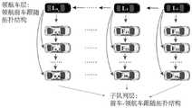
图1是本发明中单车道多队列系统的示意图。单车道多队列系统由多个子队列构成,所有子队列顺序行驶在同一条车道上;每个子队列由一辆领航车和若干跟随车组成,每个子队列内部跟随车采用本发明设计的控制器进行车辆控制;其中,系统中第一个子队列的领航车为人工驾驶或理想运动状态;后方子队列的领航车为自动驾驶模式,由本发明设计的控制器进行车辆控制;各个子队列之间通过通信网络进行信息交互,以达到多队列协同控制的目标。每辆车上均配备本发明所述分布式模型预测控制器,根据邻域车辆信息来控制自身车辆行为。图1中,共包含np个子队列,Li表示第i个子队列领航车,Fij表示第i个子队列中的第j辆跟随车,各车编号由子队列数量、跟随车数量等参数确定,将在后续部分详细叙述。FIG. 1 is a schematic diagram of a single-lane multi-queue system in the present invention. The single-lane multi-queue system is composed of multiple sub-queues, and all the sub-queues drive on the same lane in sequence; each sub-queue is composed of a leading car and several following cars, and the following cars in each sub-queue use the controller designed by the present invention. Vehicle control; wherein, the pilot car of the first sub-queue in the system is in manual driving or ideal motion state; the pilot car of the rear sub-queue is in automatic driving mode, and the vehicle is controlled by the controller designed by the present invention; The communication network conducts information exchange to achieve the goal of multi-queue cooperative control. Each vehicle is equipped with the distributed model predictive controller of the present invention, which controls the behavior of its own vehicle according to the information of the neighboring vehicles. In Figure 1, there are a total of np sub-queues,Li represents the ith sub-queue leader vehicle, F ijrepresents the j-th following vehicle in the ith sub-queue, and the number of each vehicle is determined by the number of sub-queues, the number of following vehicles and other parameters, It will be described in detail in subsequent sections.
本发明提出一种领航车队协同的单车道多队列分层控制方法,整体流程如图2所示,包括以下步骤;The present invention proposes a single-lane multi-queue layered control method for the coordination of pilot fleets, and the overall process is shown in Figure 2, including the following steps;
1)在单车道上,构建由多个单车队列组成的单车道多队列系统,其中,所有单车队列的领航车构成单车道多队列系统的领航车层,每个单车队列中的领航车以及其所有跟随车组成一个子队列,所有子队列组成子队列层;1) On a single lane, construct a single-lane multi-queue system composed of multiple single-vehicle queues, in which the pilot cars of all single-vehicle queues constitute the pilot car layer of the single-lane multi-queue system, and the pilot vehicles in each single-vehicle queue and all its The following car forms a sub-queue, and all sub-queues form a sub-queue layer;
确定子队列数量np、每个子队列内跟随车数量集合


将每个子队列的领航车构成单车道多队列系统的领航车层,该层以队列方式进行协同控制。如图3所示为领航车层和子队列层的分层示意图,其中Li表示第i个子队列领航车,Fij表示第i个子队列中的第j辆跟随车,图中领航车L1,L2,…,Lnp构成领航车层,每个领航车Li与其nFi个跟随车共同构成一个子队列,共np个子队列构成子队列层。The pilot cars of each sub-queue constitute the pilot car layer of the single-lane multi-queue system, and this layer performs cooperative control in a queue mode. Figure 3 is a hierarchical schematic diagram of the pilot vehicle layer and the sub-queue layer, whereLi represents the ith sub-queue leader vehicle, and F ijrepresents the j-th follower vehicle in the ith sub-queue. In the figure, the leader vehicle L1 , L2 , ..., Lnp constitute the leading car layer, each leading car Li and itsnFi following cars together constitute a sub-queue, and a total of np sub-queues constitute the sub-queue layer.
设定每个子队列内部的期望跟车距离d和相邻子队列之间的期望跟车距离D;所述子队列内部的期望跟车距离为各子队列内部跟随车与前方车辆之间的期望间距;所述子队列之间的期望跟车距离存在两种定义方式,分别为所在子队列领航车与前方子队列尾车之间的期望间距D1,和所在子队列领航车与前方子队列领航车之间的期望间距D2。本发明中以D=D2为例进行论述,当采用D=D1定义方法时可以通过相似的方法得到多队列控制器设计结果。本发明中采用固定车间距控制策略,即d和D为常数。一般情况下子队列之间的车间距要大于子队列内跟车距离,即D>d。Set the expected following distance d within each sub-queue and the expected following distance D between adjacent sub-queues; the expected following distance within the sub-queue is the expected distance between the following vehicle within each sub-queue and the vehicle ahead Distance; there are two ways to define the expected following distance between the sub-queues, namely the expected distance D1 between the leader car of the sub-queue and the tail car of the preceding sub-queue, and the expected
2)确定单车道多队列系统的信息流拓扑结构,分别建立领航车层的领航牵引矩阵和领航邻接矩阵以及各子队列的跟随车牵引矩阵和跟随车邻接矩阵。具体步骤如下:2) Determine the information flow topology of the single-lane multi-queue system, and establish the leading traction matrix and the leading adjacency matrix of the leading vehicle layer and the following vehicle traction matrix and the following vehicle adjacency matrix of each sub-queue respectively. Specific steps are as follows:
2-1)确定单车道多队列系统的信息流拓扑结构,其中,领航车层互相通信以确定各子队列领航车的行驶状态,并进一步指导该领航车所属子队列内跟随车的行驶状态;考虑到子队列长度和通信距离的限制,领航车层采用领航前车跟随式拓扑结构,即每个子队列领航车接收前方相邻的一个子队列领航车的信息并进行跟随控制。子队列层则采用前车-领航车跟随式拓扑结构,即每个子队列中的跟随车接收前方相邻一个跟随车以及所属子队列的领航车的信息进行跟随控制(如果任一子队列中该跟随车为领航车后第一辆跟随车,则该车只接收领航车的信息)。2-1) Determine the information flow topology of the single-lane multi-queue system, wherein the pilot vehicle layer communicates with each other to determine the driving status of the leading vehicles of each sub-queue, and further guide the driving status of the following vehicles in the sub-queue to which the pilot vehicle belongs; Considering the limitation of sub-queue length and communication distance, the leading car layer adopts the topological structure of the leading car following the leading car, that is, each sub-queue leading car receives the information of the adjacent sub-queue leading car in front and performs following control. The sub-queue layer adopts the following topology structure of the leading car and the leading car, that is, the following car in each sub-queue receives the information of the adjacent following car in front and the leader car of the sub-queue to follow control (if the following car in any sub-queue receives the information of the leading car in the sub-queue) If the following car is the first following car after the lead car, the car only receives the information of the lead car).
本发明中,领航车层和子队列层信息流拓扑结构如图4所示。其中,箭头代表信息的传递方向。In the present invention, the topological structure of the information flow of the pilot vehicle layer and the sub-queue layer is shown in FIG. 4 . Among them, the arrow represents the direction of information transmission.
信息流拓扑结构由牵引矩阵和邻接矩阵描述。其中牵引矩阵用于描述跟随车获得领航车信息的情况,假设一个车辆队列中共有M辆跟随车,则牵引矩阵定义为P=diag(p1,p2,…,pM),其中pi为矩阵P的对角元素,若车辆i能够获得其对应的领航车辆的状态信息,则pi=1,否则pi=0。邻接矩阵用于描述车辆i获取其他跟随车辆信息的情况,定义为
则对于领航前车跟随式拓扑结构的单车道多队列系统,领航车层的领航牵引矩阵和领航邻接矩阵,以及子队列层的子队列牵引矩阵、子队列邻接矩阵可由以下方法得到:Then, for a single-lane multi-queue system with a leading vehicle-following topology, the pilot traction matrix and pilot adjacency matrix of the pilot vehicle layer, and the sub-queue traction matrix and sub-queue adjacency matrix of the sub-queue layer can be obtained by the following methods:
2-2)确定领航车层的领航牵引矩阵和领航邻接矩阵;2-2) Determine the pilot traction matrix and the pilot adjacency matrix of the pilot vehicle layer;
领航车层的领航车为车辆1。则对于除车辆1外的每一辆领航车层的车辆nLi,若其能够获得车辆1的信息,则领航车层的领航牵引矩阵PL中的对应元素


领航车层采用领航前车跟随式拓扑结构,则根据上述原则,可确定领航牵引矩阵PL和领航邻接矩阵为:The pilot vehicle layer adopts the leading vehicle-following topology structure. According to the above principles, the pilot traction matrixPL and the pilot adjacency matrix can be determined as:


其中,PL为领航牵引矩阵,

2-3)确定各子队列跟随车的子队列牵引矩阵和子队列邻接矩阵。2-3) Determine the sub-queue traction matrix and sub-queue adjacency matrix of the following vehicles of each sub-queue.
各子队列的信息流拓扑结构采用前车领航车跟随式(PLF)。根据任一跟随车辆i的编号(i为1至N中的属于跟随车辆的任一编号)可确定其所属子队列编号k及所属子队列领航车编号nLk,且该子队列内共有nFk个跟随车。则对于属于第k个子队列的车辆i,若其能够获得其所属子队列领航车辆nLk的信息,则该车辆i在所属子队列的跟随车牵引矩阵Psk中的对应元素pi=1,其中pi为指示车辆i能否获得所在子队列领航车nLk信息的变量,能够获得领航车信息时取1;反之,pi=0。根据子队列拓扑结构,可确定车辆i所属子队列的跟随车邻接矩阵元素,其中其中aij为指示车辆i能否获取相同子队列内车辆j信息的变量,能够获取时取1,否则aij=0。The information flow topology of each sub-queue adopts the leading vehicle following type (PLF). According to the number of any following vehicle i (i is any number from 1 to N belonging to the following vehicle), the sub-queue number k to which it belongs and the sub-queue leader vehicle number nLk to which it belongs can be determined, and there is a total of nFk in the sub-queue a follower car. Then for the vehicle i belonging to the kth sub-queue, if it can obtain the information of the leading vehicle nLk of the sub-queue to which it belongs, the corresponding element pi =1 of the vehicle i in the following vehicle traction matrix Psk of the sub-queue to which it belongs, Among them, pi is a variable indicating whether vehiclei can obtain the information of the pilot vehicle nLk of the sub-queue where it belongs, and takes 1 when the information of the pilot vehicle can be obtained; otherwise,pi =0. According to the sub-queue topology, the following vehicle adjacency matrix elements of the sub-queue to which vehicle i belongs can be determined, where aij is a variable indicating whether vehicle i can obtain the information of vehicle j in the same sub-queue, 1 when it can be obtained, otherwise aij =0.
因此,可确定该子队列的跟随车牵引矩阵和跟随车邻接矩阵分别为:Therefore, it can be determined that the following vehicle traction matrix and the following vehicle adjacency matrix of the sub-queue are respectively:
pi=1 i=nLk+1,nLk+2,...,nLk+nFk,pi =1 i=nLk +1,nLk +2,...,nLk +nFk ,


其中PSk、ASk分别为第k个子队列跟随车的子队列牵引矩阵和子队列邻接矩阵。Among them, PSk and ASk are respectively the sub-queue traction matrix and the sub-queue adjacency matrix of the k-th sub-queue following car.
对于单车道多队列系统中的各子队列,可分别依据上述原则写出对应的该子队列的跟随车牵引矩阵和跟随车邻接矩阵。For each sub-queue in the single-lane multi-queue system, the corresponding following vehicle traction matrix and following vehicle adjacency matrix of the sub-queue can be written according to the above principles.
对于任一节点i,在确定其所处子队列以及是否为领航车后,均可根据相应的牵引矩阵和邻接矩阵确定其可以获取信息的通信对象。For any node i, after determining its sub-queue and whether it is a pilot vehicle, it can determine the communication object that it can obtain information from according to the corresponding traction matrix and adjacency matrix.
3)设计单车道多队列分布式模型预测DMPC控制器。该控制器由依次连接的数据接收及处理模块、DMPC控制器模块和数据发送模块构成,结构如图5所示。3) Design a single-lane multi-queue distributed model to predict the DMPC controller. The controller consists of a data receiving and processing module, a DMPC controller module and a data sending module, which are connected in sequence, and the structure is shown in Figure 5.
数据接收及处理模块根据步骤2)得到的多队列系统的信息流拓扑结构,接收邻域车辆发送的该邻域车辆的假设输出序列,采集自车当前时刻(t时刻)状态信息及上一时刻(t-1时刻)计算出的当前时刻(t时刻)自车假设输出序列;根据步骤1)确定的子队列跟车距离、队列之间的跟车距离确定自车期望位置,并发送给DMPC控制器模块。According to the information flow topology of the multi-queue system obtained in step 2), the data receiving and processing module receives the hypothetical output sequence of the neighboring vehicle sent by the neighboring vehicle, and collects the current time (time t) state information of the vehicle and the previous time. (time t-1) the calculated output sequence of the self-vehicle at the current time (time t); the expected position of the self-vehicle is determined according to the following distance of the sub-queue and the vehicle-following distance between the queues determined in step 1), and sent to the DMPC controller module.
DMPC控制器模块中,建立车辆非线性纵向动力学模型;根据上一时刻计算出的自车在当前时刻的假设输出序列、自车期望位置、自车当前时刻状态、车辆非线性动力学模型,分别设计领航分布式模型预测控制器和子队列分布式模型预测控制器。求解各分布式模型预测控制器的优化模型得到对应车辆当前时刻的最优控制序列,并将最优控制序列的第一个值用于该车辆控制,同时利用该最优控制序列计算自车下一时刻假设输出序列,并发送给数据发送模块。In the DMPC controller module, the nonlinear longitudinal dynamics model of the vehicle is established; according to the assumed output sequence of the ego vehicle at the current moment calculated at the previous moment, the expected position of the ego vehicle, the current state of the ego vehicle, and the nonlinear dynamic model of the vehicle, The pilot distributed model predictive controller and the sub-queue distributed model predictive controller are designed respectively. Solve the optimization model of each distributed model predictive controller to obtain the optimal control sequence corresponding to the current time of the vehicle, and use the first value of the optimal control sequence for the vehicle control, and use the optimal control sequence to calculate the self-vehicle Assume the output sequence at one moment and send it to the data sending module.
数据发送模块向其他车辆发送数据,所述数据均带有时间戳、数据发出车辆的编号以及该车辆下一时刻的假设输出序列,且发送不存在时延、丢包等非理想通信特性。其中车辆j假设输出序列Yja定义为车辆j若根据t时刻的最优控制序列进行车辆控制将会在预测时域内产生的输出序列,由车辆j的DMPC控制器模块计算得到。The data sending module sends data to other vehicles, and the data has a timestamp, the serial number of the vehicle sending the data, and the assumed output sequence of the vehicle at the next moment, and there is no non-ideal communication characteristics such as delay and packet loss. Among them, the assumed output sequence Yja of vehicle j is defined as the output sequence that will be generated in the predicted time domain if vehicle j performs vehicle control according to the optimal control sequence at time t, which is calculated by the DMPC controller module of vehicle j.
其中,分布式控制器模块的建立可分为如下步骤:Among them, the establishment of the distributed controller module can be divided into the following steps:
3-1)建立车辆非线性动力学模型;3-1) Establish a nonlinear dynamic model of the vehicle;
对于单车道多队列系统中任一被控车辆i(i≠1)(本发明中被控车辆为单车道多队列系统中除车辆1外的其他车辆),为更加准确地描述车辆行驶过程,采用如下非线性动力学模型:For any controlled vehicle i (i≠1) in the single-lane multi-queue system (in the present invention, the controlled vehicle is a vehicle other than

其中,t为控制时刻,pi(t)和vi(t)分别为车辆i在t时刻的位移和速度,mi为车辆i的质量,CA,i为车辆i的集总空气阻力系数,g为重力加速度常数,fi为车辆i的滚动阻力系数,Ti(t)为车辆i在t时刻的实际驱动/制动力的力矩,ui(t)为车辆i在t时刻的期望驱动/制动力矩,τi为车辆i纵向动力系统的时滞常数,rw,i为车辆i的车轮半径,ηT,i为车辆i的传动系统的机械效率。where t is the control time, pi (t) and vi (t) are the displacement and velocity of vehiclei at time t, respectively,mi is the mass of vehicle i, and CA,i is the aggregate air resistance of vehicle i coefficient, g is the gravitational acceleration constant, fi is the rolling resistance coefficient of vehicle i, Ti (t) is the torque of the actual driving/braking force of vehicle i at time t,ui (t) is the torque of vehicle i at time t Desired driving/braking torque, τi is the time lag constant of the longitudinal powertrain of vehicle i, rw,i is the wheel radius of vehicle i, and ηT,i is the mechanical efficiency of the drivetrain of vehicle i.
将车辆i的t时刻状态记为xi(t)=[pi(t),vi(t),Ti(t)]T,t时刻的控制输入记为ui(t)。离散步长为Δt,则该车辆动力学模型可以离散为:The state of the vehicle i at time t is denoted as xi (t)=[pi (t),vi (t),Ti( t)]T , and the control input at time t is denoted asui (t). If the discretization step is Δt, the vehicle dynamics model can be discretized as:

进一步可以写作:xi(t+1)=φi(xi(t))+ψiui(t),i=2,...,N;It can be further written as: xi (t+1)=φi (xi (t))+ψi ui (t), i=2,...,N;
其中,in,

车辆i在t时刻的输出方程为:yi(t)=[pi(t),vi(t)]T=γxi(t),其中
3-2)构建分布式模型预测控制器;3-2) Build a distributed model predictive controller;
接下来构建DMPC控制器。将单车道多队列系统中每一辆车作为一个节点,在除车辆1外的每个车辆节点上定义一个分布式模型预测控制器的优化模型。每个优化模型只利用该节点邻域车辆节点的信息进行优化求解,得到该节点的控制输入,则共建立N-1个分布式模型预测控制器的优化模型。Next build the DMPC controller. Taking each vehicle in the single-lane multi-queue system as a node, an optimization model of the distributed model predictive controller is defined on each vehicle node except
在这N个优化模型中,预测步长均为Np,控制步长均为Nc。在每个时刻的预测时域内[t,t+Np],均定义三个控制输入序列:预测控制输入序列


3-2-1)构建领航分布式模型预测控制器优化模型;具体步骤如下:3-2-1) Build a pilot distributed model predictive controller optimization model; the specific steps are as follows:
3-2-1-1)领航车层采用PF拓扑结构,从第二辆领航车起,每辆车只接收前一辆领航车的信息,则其模型预测控制器的目标函数要考虑三个方面。对于除车辆1节点外的每个领航车节点i,i=2,...,np,其领航分布式模型预测控制器优化模型的目标函数表达式为:3-2-1-1) The pilot car layer adopts PF topology structure. From the second pilot car, each car only receives the information of the previous pilot car, so the objective function of its model prediction controller needs to consider three aspect. For each pilot vehicle node i,i=2,...,np except the
JL=JL1+JL2+JL3JL = JL1 +JL2 +JL3
其中,in,


3-2-1-2)领航车节点i的领航分布式模型预测控制器优化模型的约束条件包括如下几项:3-2-1-2) The constraints of the pilot distributed model predictive controller optimization model of the pilot vehicle node i include the following items:


3-2-1-3)基于上述目标函数和约束条件,可以得到领航车节点i的分布式非线性模型预测控制器的优化模型为:3-2-1-3) Based on the above objective function and constraints, the optimization model of the distributed nonlinear model predictive controller of the pilot vehicle node i can be obtained as:

求解上述局部优化模型即可得到领航车辆节点i在t时刻的最优预测控制输入序列

3-2-2)构建子队列分布式模型预测控制器优化模型;3-2-2) Build a sub-queue distributed model predictive controller optimization model;
3-2-2-1)子队列层均采用PLF拓扑结构,每辆跟随车节点接收其前一辆跟随车信息,同时接收该车自身所在子队列的领航车的信息,用于自车控制。与领航车层相比,子队列层要考虑其领航车信息,因此其模型预测控制器的目标函数要考虑四个方面。对于任一子队列j,其领航车节点为nLj,子队列内跟随车数量为nFj,则对于该子队列中任一跟随车节点i,i=1,...,nFj,其子队列分布式模型预测控制器的目标函数表达式为:3-2-2-1) The sub-queue layer adopts the PLF topology structure. Each follower car node receives the information of its previous follower car, and at the same time receives the information of the leader car of the sub-queue where the car is located, which is used for self-vehicle control. . Compared with the pilot car layer, the sub-queue layer needs to consider its pilot car information, so the objective function of its model predictive controller needs to consider four aspects. For any sub-queue j, its leading vehicle node is nLj , and the number of following vehicles in the sub-queue is nFj , then for any following vehicle node i in the sub-queue, i=1,...,nFj , its The objective function expression of the sub-queue distributed model predictive controller is:
JSj=JSj1+JSj2+JSj3+JSj4JSj =JSj1 +JSj2 +JSj3 +JSj4
其中,in,


子队列跟随车节点i的分布式模型预测控制器优化模型的约束条件包括如下几项:The constraints of the distributed model predictive controller optimization model of the sub-queue following vehicle node i include the following items:


3-2-2-3)基于上述目标函数和约束条件,可以得到子队列跟随车节点i的分布式非线性模型预测控制器的优化模型为:3-2-2-3) Based on the above objective function and constraints, the optimal model of the distributed nonlinear model predictive controller of the sub-queue following vehicle node i can be obtained as:

求解上述局部优化模型即可得到子队列跟随车节点i在t时刻的最优预测控制输入序列

3-3)计算车辆假设输出序列;3-3) Calculate the vehicle hypothesis output sequence;
对于被控领航车节点(即除第一辆领航车节点外的其他领航车节点)和所有子队列跟随车节点,均需根据步骤3-2)中计算出对应的最优预测控制输入序列和车辆当前时刻状态,计算该节点在下一个时刻的预测时域中的最优状态序列:For the controlled leader vehicle node (ie, other leader vehicle nodes except the first leader vehicle node) and all sub-queue follower vehicle nodes, the corresponding optimal predictive control input sequence and The current state of the vehicle, calculate the optimal state sequence of the node in the prediction time domain at the next time:


其中,xi(t)=[pi(t),vi(t),Ti(t)]T为节点i在t时刻的自车状态,可由多种途径获得,如通过定位系统获得车辆位置pi(t),由轮速传感器经换算获得车辆速度vi(t),由车辆动力系统参数和转速等状态计算获得车辆实际转矩Ti(t);Among them, xi (t)=[pi (t), vi (t), Ti (t)]T is theego vehicle state of node i at time t, which can be obtained by various methods, such as obtaining through the positioning system Vehicle position pi (t), the vehicle speed vi (t) is obtained by conversion from the wheel speed sensor, and the actual vehicle torque Ti (t) is obtained by calculating the state of the vehicle power system parameters and rotational speed;
计算该节点t+1时刻的假设输入序列:Compute the hypothetical input sequence at time t+1 for this node:

得到该节点t+1时刻的相应的假设输出轨迹为:The corresponding hypothetical output trajectory of the node at time t+1 is obtained as:


则车辆节点i t+1时刻的假设输出序列为:Then the hypothetical output sequence at the time of vehicle node i t+1 is:

车辆节点i将该序列通过无线通信传输给其他车辆。Vehicle node i transmits the sequence to other vehicles via wireless communication.
数据发送模块将自车ID、自车假设输出序列打包,根据领航及子队列牵引矩阵、邻接矩阵,通过通信网络将打包好的数据发送给需要接收该数据包的车辆。具体地,对于领航车节点,其需要在领航车层和子队列层同时发送信息,在领航车层,根据领航牵引矩阵和领航邻接矩阵元素,将自车信息发送给后方领航车;在子队列层,领航车需根据该子队列的子队列牵引矩阵将自车信息发送给所有子队列跟随车。对于子队列层,跟随车需根据子队列邻接矩阵元素将自车信息发送给后方跟随车。The data sending module packages the self-vehicle ID and the self-vehicle hypothesis output sequence, and sends the packaged data to the vehicle that needs to receive the data packet through the communication network according to the pilot and sub-queue traction matrix and adjacency matrix. Specifically, for the pilot vehicle node, it needs to send information at the pilot vehicle layer and the sub-queue layer at the same time. At the pilot vehicle layer, according to the elements of the pilot traction matrix and the pilot adjacency matrix, the self-vehicle information is sent to the rear pilot vehicle; at the sub-queue layer , the leading car needs to send the information of its own car to the following cars of all sub-queues according to the sub-queue traction matrix of the sub-queue. For the sub-queue layer, the following car needs to send its own car information to the following car according to the elements of the sub-queue adjacency matrix.
根据上述方法可以构建出单车道多队列系统的统一模型,并分别针对领航车层和子队列层的车辆设计了分布式模型预测控制器,以进行车辆运动控制。在应用过程中可按照如图6所示的流程进行多队列控制。According to the above method, a unified model of a single-lane multi-queue system can be constructed, and a distributed model predictive controller is designed for the vehicles at the pilot vehicle layer and the sub-queue layer to control vehicle motion. In the application process, multi-queue control can be performed according to the flow shown in FIG. 6 .
A.程序初始化。A. Program initialization.
该步骤包括单车道多队列系统的建立和控制器初始化等内容。根据车车通信内容获得多队列的相关参数,包括自车所处子队列的编号、自车所处子队列领航车的编号、自车编号、与前车的期望车间距等。进行控制器的初始化,即假设当前为t=0时刻,假设所有车辆均处于匀速运动,控制量为保持车辆匀速运动的值,则可通过车辆动力学模型迭代计算节点i上的假设输入与输出序列,以用于后续控制器计算。This step includes the establishment of the single-lane multi-queue system and the initialization of the controller. Relevant parameters of multiple queues are obtained according to the content of the vehicle-to-vehicle communication, including the number of the sub-queue where the vehicle is located, the number of the leader car of the sub-queue where the vehicle is located, the number of the vehicle, and the expected distance between the vehicle and the preceding vehicle. Initialize the controller, that is, assuming that the current time is t=0, assuming that all vehicles are moving at a uniform speed, and the control amount is the value that keeps the vehicle moving at a uniform speed, then the hypothetical input and output on node i can be iteratively calculated through the vehicle dynamics model sequence for subsequent controller calculations.
B.自车身份判断。B. Judging the identity of the vehicle.
根据自车编号和领航车编号判断自车是否为领航车,若是,则跳转C,否则跳转D;According to the number of the vehicle and the number of the pilot vehicle, determine whether the vehicle is the pilot vehicle. If so, jump to C, otherwise, jump to D;
C.领航车控制。C. Pilot car control.
在每一时刻t,除第1领航车外的其他领航车i采集当前时刻自车状态xi(t)、上一时刻(即t-1时刻)前方相邻领航车j发送的t时刻的该领航假设输出序列


D.子队列跟随车控制。D. Sub-queue following car control.
在每一时刻t,每辆子队列跟随车i采集当前时刻自车状态xi(t)、上一时刻(即t-1时刻)前车j发送的t时刻的该跟随车j的假设输出序列


Claims (1)


Priority Applications (1)
| Application Number | Priority Date | Filing Date | Title |
|---|---|---|---|
| CN202011219390.3ACN112445229B (en) | 2020-11-04 | 2020-11-04 | Single-lane multi-queue hierarchical control method for piloting motorcade cooperation |
Applications Claiming Priority (1)
| Application Number | Priority Date | Filing Date | Title |
|---|---|---|---|
| CN202011219390.3ACN112445229B (en) | 2020-11-04 | 2020-11-04 | Single-lane multi-queue hierarchical control method for piloting motorcade cooperation |
Publications (2)
| Publication Number | Publication Date |
|---|---|
| CN112445229A CN112445229A (en) | 2021-03-05 |
| CN112445229Btrue CN112445229B (en) | 2021-10-26 |
Family
ID=74735647
Family Applications (1)
| Application Number | Title | Priority Date | Filing Date |
|---|---|---|---|
| CN202011219390.3AActiveCN112445229B (en) | 2020-11-04 | 2020-11-04 | Single-lane multi-queue hierarchical control method for piloting motorcade cooperation |
Country Status (1)
| Country | Link |
|---|---|
| CN (1) | CN112445229B (en) |
Cited By (1)
| Publication number | Priority date | Publication date | Assignee | Title |
|---|---|---|---|---|
| US12298774B2 (en) | 2022-05-03 | 2025-05-13 | Smart Information Flow Technologies, LLC | Computer architecture for identification of nonlinear control policies |
Families Citing this family (16)
| Publication number | Priority date | Publication date | Assignee | Title |
|---|---|---|---|---|
| CN113485329B (en)* | 2021-07-01 | 2022-07-01 | 西北工业大学 | A kind of vehicle multi-platoon cooperative control method |
| CN113568409B (en)* | 2021-07-29 | 2022-03-18 | 湖南大学无锡智能控制研究院 | Vehicle queue control method and system considering random packet loss in communication |
| CN114326759B (en)* | 2021-12-06 | 2023-12-22 | 中国农业大学 | Multi-agent formation control method and device and multi-agent system |
| CN114179803B (en)* | 2021-12-29 | 2024-04-05 | 吉林大学 | Mining dump truck two-dimensional queue control system based on virtual spring damping |
| CN114510032A (en)* | 2022-01-06 | 2022-05-17 | 东南大学 | A multi-vehicle cooperative control method and device for ensuring rapid vehicle formation and stability |
| CN114684202B (en)* | 2022-06-01 | 2023-03-10 | 浙江大旗新能源汽车有限公司 | Intelligent system for automatically driving vehicle and integrated control method thereof |
| CN115237118B (en)* | 2022-06-01 | 2024-08-09 | 昆明理工大学 | A V2V vehicle platoon formation strategy optimization method |
| CN114995138A (en)* | 2022-06-02 | 2022-09-02 | 重庆大学 | Distributed cooperative control method for mixed vehicle group in near signal control area |
| CN115497281B (en)* | 2022-08-16 | 2024-03-19 | 清华大学 | Robust model predictive control method for multiple queues of pilot vehicles in mixed traffic scenarios |
| CN115547025B (en)* | 2022-08-29 | 2023-05-05 | 东南大学 | A Heterogeneous Vehicle Platoon Stability Control Method for Random Vehicle-to-Vehicle Communication Links |
| CN115469646B (en)* | 2022-09-28 | 2024-11-05 | 吉林大学 | Cooperative control method for heterogeneous queues of semi-trailer trains based on distributed model predictive control |
| CN116386387B (en)* | 2023-04-19 | 2024-03-08 | 长安大学 | Method and device for predicting car-following behavior of mixed queues of human-driven vehicles |
| CN116400631B (en)* | 2023-04-25 | 2025-09-09 | 重庆交通大学 | DMPC-based zero-trust intelligent network-connected vehicle queue control method under communication interruption |
| CN117492448A (en)* | 2023-12-28 | 2024-02-02 | 北京主线科技有限公司 | Vehicle formation method, device, equipment and storage medium |
| CN119512101A (en)* | 2024-11-14 | 2025-02-25 | 湖南大学 | A multi-vehicle cooperative control method and system considering time-varying directed communication topology |
| CN119987429B (en)* | 2025-04-14 | 2025-07-15 | 长沙理工大学 | Multi-vehicle platoon cooperative control method and medium based on distributed model predictive control |
Citations (3)
| Publication number | Priority date | Publication date | Assignee | Title |
|---|---|---|---|---|
| CN103956045A (en)* | 2014-05-13 | 2014-07-30 | 中国人民解放军军事交通学院 | Method for achieving collaborative driving of vehicle fleet by means of semi-physical simulation technology |
| CN108973998A (en)* | 2018-07-11 | 2018-12-11 | 清华大学 | A kind of heterogeneous vehicle platoon distribution energy-saving control method based on MPC |
| CN110329257A (en)* | 2019-06-24 | 2019-10-15 | 武汉理工大学 | A kind of more longitudinally controlled methods of car team team based on Che-Che Tongxin |
Family Cites Families (1)
| Publication number | Priority date | Publication date | Assignee | Title |
|---|---|---|---|---|
| US20090210081A1 (en)* | 2001-08-10 | 2009-08-20 | Rockwell Automation Technologies, Inc. | System and method for dynamic multi-objective optimization of machine selection, integration and utilization |
- 2020
- 2020-11-04CNCN202011219390.3Apatent/CN112445229B/enactiveActive
Patent Citations (3)
| Publication number | Priority date | Publication date | Assignee | Title |
|---|---|---|---|---|
| CN103956045A (en)* | 2014-05-13 | 2014-07-30 | 中国人民解放军军事交通学院 | Method for achieving collaborative driving of vehicle fleet by means of semi-physical simulation technology |
| CN108973998A (en)* | 2018-07-11 | 2018-12-11 | 清华大学 | A kind of heterogeneous vehicle platoon distribution energy-saving control method based on MPC |
| CN110329257A (en)* | 2019-06-24 | 2019-10-15 | 武汉理工大学 | A kind of more longitudinally controlled methods of car team team based on Che-Che Tongxin |
Non-Patent Citations (2)
| Title |
|---|
| 智能网联混合动力汽车队列模型预测分层控制;郭景华等;《汽车工程》;20201025(第10期);第1293-1301页* |
| 网联环境下基于分层式模型预测控制的车队能量控制策略研究;唐小林等;《机械工程学报》;20200720;第56卷(第14期);第119-127页* |
Cited By (1)
| Publication number | Priority date | Publication date | Assignee | Title |
|---|---|---|---|---|
| US12298774B2 (en) | 2022-05-03 | 2025-05-13 | Smart Information Flow Technologies, LLC | Computer architecture for identification of nonlinear control policies |
Also Published As
| Publication number | Publication date |
|---|---|
| CN112445229A (en) | 2021-03-05 |
Similar Documents
| Publication | Publication Date | Title |
|---|---|---|
| CN112445229B (en) | Single-lane multi-queue hierarchical control method for piloting motorcade cooperation | |
| Wang et al. | Model predictive control for connected vehicle platoon under switching communication topology | |
| CN108877256B (en) | Wireless communication-based method for controlling scattered cooperative self-adaptive cruise near intersection | |
| CN112437412B (en) | A vehicle formation control method for mixed driving vehicles based on vehicle-road coordination | |
| CN113593275B (en) | Intersection internet automatic driving method based on bus signal priority | |
| CN108973998A (en) | A kind of heterogeneous vehicle platoon distribution energy-saving control method based on MPC | |
| CN113012448B (en) | An intelligent driving system for vehicle distribution and formation to solve traffic congestion at intersections | |
| CN114999227B (en) | Non-signal control intersection mixed multi-vehicle model-free prediction cooperative control method | |
| CN111959492A (en) | HEV energy management hierarchical control method considering lane change behavior in networking environment | |
| CN114253274A (en) | Data-driven-based online hybrid vehicle formation rolling optimization control method | |
| CN117429431A (en) | Channel switching decision and time delay compensation control method and device based on prediction information | |
| CN117935532A (en) | Vehicle green wave passing planning method and device, electronic equipment and storage medium | |
| CN117601929A (en) | High-speed train formation anti-collision control method based on deep learning | |
| CN113140108B (en) | Cloud traffic situation prediction method in internet-connected intelligent traffic system | |
| Zhao et al. | Consensus control of highway on-ramp merging with communication delays | |
| CN114463974A (en) | Cooperative control system and method of mixed vehicle group under the condition of priority right of way | |
| CN114510032A (en) | A multi-vehicle cooperative control method and device for ensuring rapid vehicle formation and stability | |
| CN115830885B (en) | A coordinated control method for vehicle ramp merging considering energy consumption of multiple vehicle types | |
| CN117315935A (en) | Intelligent vehicle team following control method based on motion state estimation under communication delay | |
| CN112258864A (en) | Method and system for automatic driving vehicle intersection scheduling based on sequence selection | |
| Li et al. | A time and energy efficient merging control for platoon formation of connected and automated electric vehicles at on-ramps | |
| CN113485329B (en) | A kind of vehicle multi-platoon cooperative control method | |
| Song et al. | Switching multi-objective receding horizon control for CACC of mixed vehicle strings | |
| Tiganasu et al. | Design and simulation evaluation of cooperative adaptive cruise control for a platoon of vehicles | |
| CN118506591A (en) | SPAT unidirectional heterogeneous communication topology based intelligent network connection hybrid electric vehicle queue layered control method |
Legal Events
| Date | Code | Title | Description |
|---|---|---|---|
| PB01 | Publication | ||
| PB01 | Publication | ||
| SE01 | Entry into force of request for substantive examination | ||
| SE01 | Entry into force of request for substantive examination | ||
| GR01 | Patent grant | ||
| GR01 | Patent grant |