CN112444245B - An insect-like vision integrated navigation method based on polarized light, optical flow vector and binocular vision sensor - Google Patents
An insect-like vision integrated navigation method based on polarized light, optical flow vector and binocular vision sensorDownload PDFInfo
- Publication number
- CN112444245B CN112444245BCN202011289488.6ACN202011289488ACN112444245BCN 112444245 BCN112444245 BCN 112444245BCN 202011289488 ACN202011289488 ACN 202011289488ACN 112444245 BCN112444245 BCN 112444245B
- Authority
- CN
- China
- Prior art keywords
- polarized light
- optical flow
- navigation
- point
- sensor
- Prior art date
- Legal status (The legal status is an assumption and is not a legal conclusion. Google has not performed a legal analysis and makes no representation as to the accuracy of the status listed.)
- Active
Links
Images


Classifications
- G—PHYSICS
- G01—MEASURING; TESTING
- G01C—MEASURING DISTANCES, LEVELS OR BEARINGS; SURVEYING; NAVIGATION; GYROSCOPIC INSTRUMENTS; PHOTOGRAMMETRY OR VIDEOGRAMMETRY
- G01C21/00—Navigation; Navigational instruments not provided for in groups G01C1/00 - G01C19/00
- G01C21/005—Navigation; Navigational instruments not provided for in groups G01C1/00 - G01C19/00 with correlation of navigation data from several sources, e.g. map or contour matching
- G—PHYSICS
- G01—MEASURING; TESTING
- G01C—MEASURING DISTANCES, LEVELS OR BEARINGS; SURVEYING; NAVIGATION; GYROSCOPIC INSTRUMENTS; PHOTOGRAMMETRY OR VIDEOGRAMMETRY
- G01C21/00—Navigation; Navigational instruments not provided for in groups G01C1/00 - G01C19/00
- G01C21/20—Instruments for performing navigational calculations
Landscapes
- Engineering & Computer Science (AREA)
- Radar, Positioning & Navigation (AREA)
- Remote Sensing (AREA)
- Automation & Control Theory (AREA)
- Physics & Mathematics (AREA)
- General Physics & Mathematics (AREA)
- Navigation (AREA)
Abstract
Description
Translated fromChinese技术领域technical field
本发明属于仿生组合导航领域,涉及一种仿昆虫组合导航系统及其定位方法,尤其涉及基于光流矢量、偏振光、双目视觉传感器组合导航系统测试平台搭建及定位方法。The invention belongs to the field of bionic integrated navigation, and relates to an insect-like integrated navigation system and a positioning method thereof, in particular to a test platform construction and positioning method for an integrated navigation system based on optical flow vector, polarized light, and binocular vision sensors.
背景技术Background technique
目前的常见的导航技术主要有惯性导航、卫星导航、天文导航、地磁导航等。惯性导航属自主式导航,具有短时精度高、不受干扰等优点,但是由于积分过程会产生累积误差,并且时间越长,误差就会越大,因此不适合远距离、耗时长的导航;卫星导航是一种非自主式导航方式,具有全球性、全天候的特性,但是它易受干扰,在有高大建筑的街道、茂密的丛林中无法正常使用,目前常用的有GPS和北斗卫星导航;天文导航是一种可以根据已知天体位置来计算载体当前航向和所处位置的导航技术,属于自主式导航,这种导航方式最大的缺点是精度低、集成度不高;地磁导航是利用地磁场分布规律测量并计算得到载体姿态信息,属于自主式导航,无误差累积,但它很容易受周围磁性材料产生磁场的影响。现有技术中公开的专利号:(CN103323005A),提出一种SINS/GPS/偏振光组合导航系统多目标优化抗干扰滤波方法,将SINS、GPS、偏振传感器以及环境中的干扰进行分类,对不同类型的干扰进行干扰建模,可建模干扰通过设计干扰观测器来抵消,通过设计干扰观测器的方法以及鲁棒技术对干扰进行干扰抵消和干扰抑制,可用于提高地球大气层内运载体的导航精度;现有技术中公开的专利号:(CN109916394A),提出融合光流位置和速度信息的组合导航算法,利用光流传感器输出的位置和速度信息以及MEMS IMU、磁力计、气压高度计、激光测距传感器的数据,采用扩展卡尔曼滤波器完成数据融合,解算出载体的位置、速度和姿态信息,因为采用磁力计,很容易受周围磁性材料产生磁场的影响,抗干扰能力不强;现有技术中公开的专利号:(CN109470237A),提出基于偏振光与地磁组合导航姿态测量方法,但只能求解姿态角α,β,γ,不具备定位导航功能;现有技术中公开的专利号:(CN108362288A),基于无迹卡尔曼滤波的偏振光SLAM方法,利用偏振光信息和激光雷达信息匹配互补、不受其他外界干扰的特性,一定程度提高了无人机SLAM系统的稳定性和精度,但无法进一步解决误匹配给导航带来的影响。The current common navigation technologies mainly include inertial navigation, satellite navigation, astronomical navigation, and geomagnetic navigation. Inertial navigation is an autonomous navigation, which has the advantages of high short-term accuracy and no interference, but because the integration process will generate cumulative errors, and the longer the time, the greater the error will be, so it is not suitable for long-distance and time-consuming navigation; Satellite navigation is a non-autonomous navigation method with global and all-weather characteristics, but it is susceptible to interference and cannot be used normally in streets with tall buildings and dense jungles. Currently, GPS and Beidou satellite navigation are commonly used; Celestial navigation is a navigation technology that can calculate the current course and location of the carrier based on the position of known celestial bodies. It belongs to autonomous navigation. The biggest disadvantage of this navigation method is low precision and low integration; The magnetic field distribution law measures and calculates the attitude information of the carrier, which belongs to autonomous navigation without error accumulation, but it is easily affected by the magnetic field generated by the surrounding magnetic materials. The patent number disclosed in the prior art: (CN103323005A), proposes a multi-objective optimization anti-jamming filtering method for SINS/GPS/polarized light integrated navigation system, classifies the interference in SINS, GPS, polarization sensors and the environment, and different Interference modeling can be carried out for different types of interference, which can be counteracted by designing an interference observer. Through the method of designing an interference observer and robust technology, the interference can be offset and suppressed, which can be used to improve the navigation of vehicles in the earth's atmosphere Accuracy; the patent number disclosed in the prior art: (CN109916394A), proposes a combined navigation algorithm that fuses optical flow position and speed information, uses the position and speed information output by the optical flow sensor and MEMS IMU, magnetometer, barometric altimeter, laser measurement The extended Kalman filter is used to complete the data fusion for the data from the distance sensor, and the position, velocity and attitude information of the carrier is calculated. Because the magnetometer is used, it is easily affected by the magnetic field generated by the surrounding magnetic materials, and the anti-interference ability is not strong; the existing The patent number disclosed in the technology: (CN109470237A), proposes a navigation attitude measurement method based on the combination of polarized light and geomagnetism, but it can only solve the attitude angles α, β, γ, and does not have the positioning and navigation function; the patent number disclosed in the prior art: (CN108362288A), based on the unscented Kalman filter polarized light SLAM method, using the characteristics of polarized light information and lidar information matching and complementary, free from other external interference, the stability and accuracy of the UAV SLAM system is improved to a certain extent, However, the impact of mismatches on navigation cannot be further resolved.
生物学家研究发现昆虫具有良好的导航能力,比如蜜蜂复眼对微小时间间隔内视觉信息的变化非常敏感,这种特点更合适处理动态信号,当蜜蜂在环境中移动时,图像的运动会在他的视网膜上形成一系列连续变化的光的“流动”信息,蜜蜂正通过分析这种动态的光流来进行导航,通过光流可以获得很多有用的信息提供导航使用;比如蟋蟀,眼部DRA区域的小眼结构的神经感杆内绒毛具有轴向规则一致,径向相互垂直的特点,该结构特点使视神经细胞具有较高的偏振光敏感特性,偏振光是天然基本物理场,携带有方位信息,蟋蟀具有三类POL-neurons,其主响应方向分别为10°,60°和130°,蟋蟀通过对三类POL-neurons输出信号进行综合处理,即可得出体轴与太阳子午线的夹角,从而实现导航功能;再比如多数昆虫具有双眼,根据双目测距原理,从不同角度观察一个场景时可以很容易的得到关于场景在距离上的感知。根据仿生导航原理当已知相机光心、两幅图片对应像素点及其距离时便可以很容易的通过三角关系得到实际场景中改点距离相机的距离,利用偏振光传感器,可以敏感的输出偏振方位角,具有不随时间累计等优点、自主性强,可以获得偏航角,通过光流可以测距,测速。Biologists have found that insects have good navigation capabilities. For example, the compound eyes of bees are very sensitive to changes in visual information in small time intervals. This feature is more suitable for processing dynamic signals. When a bee moves in the environment, the movement of the image will appear on his retina A series of continuously changing light "flow" information is formed on the surface. Bees are navigating by analyzing this dynamic light flow. Through the light flow, a lot of useful information can be obtained for navigation; for example, crickets, small eyes in the DRA area The villi in the nerve rods of the eye structure have the characteristics of consistent axial direction and perpendicular radial directions. This structural feature makes the optic nerve cells have a high sensitivity to polarized light. Polarized light is a natural basic physical field that carries orientation information. There are three types of POL-neurons, and their main response directions are 10°, 60° and 130° respectively. By comprehensively processing the output signals of the three types of POL-neurons, the cricket can obtain the angle between the body axis and the sun meridian, thus Realize the navigation function; another example is that most insects have binoculars. According to the principle of binocular ranging, when observing a scene from different angles, it is easy to get the perception of the distance of the scene. According to the principle of bionic navigation, when the optical center of the camera, the corresponding pixel points and their distances of the two pictures are known, the distance from the point to the camera in the actual scene can be easily obtained through the triangular relationship, and the polarization sensor can be used to output the polarization sensitively. The azimuth angle has the advantages of not accumulating over time, strong autonomy, can obtain the yaw angle, and can measure distance and speed through optical flow.
传统组合导航系统抗干扰能力比较弱,而无GPS或惯导组合的导航系统仅能测姿,无法定位,目前现有专利中仅将偏振光和双目传感器结合在一起使用,但并未加入光流模型和后端的优化。综上本文提出一种新型仿生组合导航方法,将双目视觉传感器、光流和偏振光传感器进行组合,提出一种新的组合导航方式,有着无线电导航和卫星导航等非自主导航方式所无法具有的隐蔽性、抗干扰性和更高的鲁棒性。The anti-jamming ability of traditional integrated navigation system is relatively weak, and the navigation system without GPS or inertial navigation combination can only measure attitude, but cannot locate. At present, only polarized light and binocular sensors are used together in existing patents, but they do not include Optimization of optical flow model and backend. In summary, this paper proposes a new bionic integrated navigation method, which combines binocular vision sensors, optical flow and polarization sensors, and proposes a new integrated navigation method, which has advantages that non-autonomous navigation methods such as radio navigation and satellite navigation cannot have. Concealment, anti-interference and higher robustness.
发明内容Contents of the invention
针对现有导航系统的抗干扰能力弱,本发明提出一种新型的仿生组合导航方法,将偏振光传感器、光流和双目视觉传感器进行组合,利用卡尔曼滤波进行数据融合,后端通过BA优化,发明一款纯依靠视觉进行导航定位的方法,抗干扰性强,具有较强的鲁棒性。Aiming at the weak anti-interference ability of the existing navigation system, the present invention proposes a new type of bionic integrated navigation method, which combines the polarized light sensor, optical flow and binocular vision sensor, uses Kalman filter for data fusion, and the back-end through BA Optimization, inventing a method of navigation and positioning purely relying on vision, with strong anti-interference and strong robustness.
本发明的技术方案:Technical scheme of the present invention:
一种基于偏振光、光流矢量、双目视觉传感器的仿昆虫视觉组合导航方法,包括以下步骤:A kind of imitation insect vision integrated navigation method based on polarized light, optical flow vector, binocular vision sensor, comprises the following steps:
步骤1:基于双目视觉传感器测量得到点P的像素坐标为[u,v]T,已知物理成像平面到小孔的距离为f(焦距),设地球坐标系下点P坐标[X,Y,Z]T,对应物理成像平面P'点的坐标为[X',Y',Z']T,像素坐标在u轴上缩放了α倍,在v上缩放了β倍,原点平移了[cx,cy]T,根据Z/f=-X/X'=-Y/Y'可得P'坐标与像素坐标[u,v]T的关系为:Step 1: Based on binocular vision sensor measurement, the pixel coordinates of point P are [u, v]T , and the distance from the physical imaging plane to the pinhole is known as f (focal length). Let the coordinates of point P in the earth coordinate system be [X, Y, Z]T , the coordinates corresponding to the point P' of the physical imaging plane are [X', Y', Z']T , the pixel coordinates are scaled by α times on the u axis, and β times on v, and the origin is translated [cx ,cy ]T , according to Z/f=-X/X'=-Y/Y', the relationship between P' coordinates and pixel coordinates [u,v]T is:

设fx=αf,fy=βf,得到像素坐标到空间坐标的转换:Let fx = αf, fy = βf, get the transformation from pixel coordinates to space coordinates:

步骤2:双目相机由左目和右目两个水平放置的相机,OL、OR为左右相机的光心,f为焦距,z为场景深度,uL、uR为成像平面的坐标,PL、PR为左右相机内成像平面上的图像点,根据相似关系可以得到:Step 2: The binocular camera consists of two horizontally placed cameras, the left eye and the right eye. OL andOR are the optical centers of the left and right cameras, f is the focal length, z is the depth of the scene, uL and uR are the coordinates of the imaging plane, PL and PR are the image points on the imaging plane of the left and right cameras, according to the similarity relationship, we can get:

步骤3:根据相机在两帧图像I1、I2之间的相对运动关系为R与t,两帧图像对应特征点进行匹配,P点的空间齐次坐标为p=[X,Y,Z,1]T,点P在I2对应点投影到像素平面上的坐标为x1=[u1,v1,1]T,根据匹配点定义增广矩阵[R|t],根据相邻图像之间的对应关系得到求解方程s·x=[R|t]·p。Step 3: According to the relative motion relationship of the camera between the two frames of images I1 and I2 is R and t, the corresponding feature points of the two frames of images are matched, and the spatially homogeneous coordinates of point P are p=[X,Y,Z ,1]T , the coordinate of point P projected onto the pixel plane at the corresponding point of I2 is x1 =[u1 ,v1 ,1]T , the augmented matrix [R|t] is defined according to the matching points, and according to the adjacent The correspondence between the images is obtained by solving the equation s·x=[R|t]·p.
步骤4:双目传感器直接得到的偏航角和位移误差比较大,使用偏振光对航向角进行修正,基于多方向偏振光传感器检测单元得到的偏振角为


步骤5:在相邻两帧之间,得到tk-1到tk时刻之间导航系统所有特征点位移矢量为


步骤6:BA优化,相机运动每帧图像可以恢复相机姿态为C1…Cm,相机观察到的路标为X1…Xn,将一个地球坐标系下的点Xj转换到相机坐标系下投影到图像上有hij=(fxXij/Xij+cx,fyYij/Zij+cy)T,可以得到函数hij=h(Ci,Xj)T,取相邻两帧(Ci,Ci+1)间所有偏振光数据集合Pi={p1…pni},反解Ci得到航向角与偏振光数据耦合,得到函数fi=f(Ci,Pj)T,求解BA优化函数:Step 6: BA optimization, each frame of camera movement can recover the camera pose as C1 ... Cm , the landmarks observed by the camera are X1 ... Xn , and convert a point Xj in the earth coordinate system to the camera coordinate system There is hij =(fx Xij /Xij +cx ,fy Yij /Zij +cy )T projected onto the image, and the function hij =h(Ci ,Xj )T can be obtained, taking All polarized light data sets between two adjacent frames (Ci , Ci+1 ) Pi ={p1 ...pni }, inversely solve Ci to get the coupling of heading angle and polarized light data, and obtain the function fi =f( Ci ,Pj )T , to solve the BA optimization function:

其中Eij与Γij分别为运动方程的协方差矩阵和偏振光数据的协方差BA优化函数取得最小时,解得优化后的参数。Where Eij and Γij are respectively the covariance matrix of the motion equation and the covariance BA optimization function of the polarized light data, the optimized parameters are solved.
步骤7:如果BA优化后,匹配特征点太少,双目视觉传感器数据丢失,采用光流速度模型短暂定位导航,等到特征点匹配较多时恢复双目视觉模型,如果匹配点够用,双目视觉传感器未丢失数据,直接执行步骤8。Step 7: If after BA optimization, there are too few matching feature points and the binocular vision sensor data is lost, use the optical flow velocity model for short-term positioning and navigation, and restore the binocular vision model when there are more feature points matched. If there are enough matching points, binocular vision sensor If the vision sensor does not lose data, go to step 8 directly.
步骤8:将一对匹配点带入到式s·x=[R|t]·p中得:Step 8: Bring a pair of matching points into the formula s·x=[R|t]·p to get:

可以得到约束方程:The constraint equation can be obtained:


定义T的行向量:Define a row vector of T:
t1=(t1,t2,t3,t4)Tt1 =(t1 , t2 , t3 , t4 )T
t2=(t5,t6,t7,t8)Tt2 =(t5 , t6 , t7 , t8 )T
t3=(t9,t10,t11,t12)Tt3 =(t9 , t10 , t11 , t12 )T
对于其它点相同表示得到方程组:For other points, the same representation results in a system of equations:

进而得到:And then get:

根据优化后的变换矩阵T解算出修正后载体的位置,速度和姿态信息。According to the optimized transformation matrix T, the position, velocity and attitude information of the corrected carrier are calculated.
本发明的有益效果:本发明采用偏振光、光流矢量和双目视觉传感器,设计纯依靠视觉进行导航定位的仿生导航系统,在不使用GPS和惯导的情况下,具有良好的导航能力,抗干扰能力强,可以在复杂环境下进行导航工作,是一种精度高、鲁棒性强的全自主导航方式。Beneficial effects of the present invention: the present invention uses polarized light, optical flow vector and binocular vision sensor to design a bionic navigation system that relies purely on vision for navigation and positioning, and has good navigation ability without using GPS and inertial navigation, It has strong anti-interference ability and can navigate in complex environments. It is a fully autonomous navigation method with high precision and strong robustness.
附图说明Description of drawings
图1为本发明系统构成示意图;Fig. 1 is a schematic diagram of the composition of the system of the present invention;
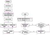
图2为本发明方法导航计算流程图;Fig. 2 is the flow chart of navigation calculation of the method of the present invention;
图3为本发明方法双目测距原理;Fig. 3 is the binocular ranging principle of the method of the present invention;
图4为本发明方法算法流程示意图;Fig. 4 is a schematic flow chart of the method algorithm of the present invention;
图5为本发明系统轴测图;Fig. 5 is an axonometric view of the system of the present invention;
图中:1双目视觉传感器;2偏振光传感器。In the figure: 1 binocular vision sensor; 2 polarized light sensor.
具体实施方式Detailed ways
以下结合附图和技术方案,进一步说明本发明的具体实施方式。The specific implementation manners of the present invention will be further described below in conjunction with the accompanying drawings and technical solutions.
步骤1:用FAST算法进行角点检测选取特征点。Step 1: Use the FAST algorithm to detect corner points and select feature points.
(1)在图像上选取像素P,假设它的亮度为Ip。(1) Select pixel P on the image, assuming its brightness is Ip .
(2)设置阈值T。(2) Set the threshold T.
(3)以像素P为中心,选取半径为3的圆上16个像素点。(3) With the pixel P as the center, select 16 pixels on a circle with a radius of 3.
(4)选取圆上亮度大于Ip+T或Ip-T的像素点为特征点。(4) Select the pixel points on the circle whose brightness is greater than Ip+T or Ip-T as feature points.
步骤2:建立相机坐标系O-x-y-z,地球坐标系下空间点P,经过光心O投影之后,落在物理成像平面O'-x'-y'上,成像点为P',P点的坐标为[X,Y,Z]T,P'点的坐标为[X',Y',Z']T,物理成像平面到小孔的距离为f(焦距)。根据三角形相似关系,可得:Step 2: Establish the camera coordinate system Oxyz, the space point P in the earth coordinate system, after being projected by the optical center O, falls on the physical imaging plane O'-x'-y', the imaging point is P', and the coordinates of point P are [X,Y,Z]T , the coordinates of point P' are [X',Y',Z']T , and the distance from the physical imaging plane to the pinhole is f (focal length). According to the triangle similarity relation, we can get:

化简可以得到:Simplification gives:

在像素平面得到了P'的像素坐标:[u,v]T。像素坐标在u轴上缩放了α倍,在v上缩放了β倍,原点平移了[cx,cy]T。P'坐标与像素坐标[u,v]T的关系为:The pixel coordinates of P' are obtained in the pixel plane: [u,v]T . The pixel coordinates are scaled α on the u axis, β on v, and the origin is translated by [cx ,cy ]T . The relationship between P' coordinates and pixel coordinates [u, v]T is:

令fx=αf,fy=βf:Let fx = αf, fy = βf:
则
将其写为矩阵的形式便得到了下面的等式:Writing this in matrix form yields the following equation:

把中间量组成的矩阵称为相机的内参矩阵,用K表示。由此可以得到像素坐标到空间坐标的转换。The matrix composed of intermediate quantities is called the internal reference matrix of the camera, represented by K. From this, the transformation from pixel coordinates to space coordinates can be obtained.
步骤3:根据双目相机成像机理可得

由像素坐标和深度信息可以的到世界坐标系下点P位置:The position of point P in the world coordinate system can be obtained from the pixel coordinates and depth information:

步骤4:特征点匹配,利用PnP求解,相机在两帧图像I1、I2之间的相对运动关系为R与t,相机中心分别为O1、O2,两帧图像之间有一组对应的特征点为p1、p2,两个特征点应为空间某一点在两成像平面中的投影,根据p1点的像素坐标并深度计算P点的空间齐次坐标为p=[X,Y,Z,1]T,点P在I2对应点p2投影到像素平面上的坐标为x1=[u1,v1,1]T,根据匹配点定义增广矩阵[R|t],根据相邻图像之间的对应关系得到求解方程s·x=[R|t]·p。Step 4: Feature point matching, using PnP to solve, the relative motion relationship of the camera between the two frames of images I1 and I2 is R and t, the centers of the cameras are O1 and O2 respectively, and there is a set of correspondence between the two frames of images The feature points are p1 and p2 , and the two feature points should be the projection of a certain point in space on two imaging planes. According to the pixel coordinates and depth of point p1 , the spatially homogeneous coordinates of point P are calculated as p=[X, Y,Z,1]T , the coordinates of point P projected onto the pixel plane corresponding to point p2 in I2 are x1 =[u1 ,v1 ,1]T , and the augmented matrix [R|t is defined according to the matching points ], according to the corresponding relationship between adjacent images, the solution equation s·x=[R|t]·p is obtained.
将上式展开可得:Expand the above formula to get:

可以得到约束方程:The constraint equation can be obtained:


定义T的行向量:Define a row vector of T:
t1=(t1,t2,t3,t4)Tt1 =(t1 , t2 , t3 , t4 )T
t2=(t5,t6,t7,t8)Tt2 =(t5 , t6 , t7 , t8 )T
t3=(t9,t10,t11,t12)Tt3 =(t9 , t10 , t11 , t12 )T
对于其它点相同表示得到方程组:For other points, the same representation results in a system of equations:

通过6对匹配点即可以实现对矩阵T的线性求解,当匹配点大于6对时使用BA优化进行求解最优值。The linear solution to the matrix T can be realized through 6 pairs of matching points. When the matching points are more than 6 pairs, BA optimization is used to solve the optimal value.
步骤5:偏振光辅助修正偏航角误差,偏振光检测单元得到的偏振角为


将相邻两帧(Ci,Ci+1)间所有偏振光数据集记为Pi={p1…pni},Pi即为偏航角。Record all polarized light data sets between two adjacent frames (Ci , Ci+1 ) as Pi ={p1 ...pni }, and Pi is the yaw angle.
步骤6:光流辅助修正,通过光流可以获得X轴和Y轴方向的速度Vx,Vy,光流传感器到相机坐标系的位姿变换为Tco,由光流传感器获得的X、Y方向的位移可得到相机坐标系下X、Y方向的位移。由恒速模型可得到当前帧与上一帧位姿之间的相对位姿,在此基础上,用传感器获得的位姿信息纠正恒速模型,使得初始的位姿具有较好的初始值。恒速模型得到的相对位姿为:Step 6: Optical flow assisted correction. The speed Vx and Vy in the X-axis and Y-axis directions can be obtained through the optical flow. The pose transformation from the optical flow sensor to the camera coordinate system is Tco . The X, V y obtained by the optical flow sensor The displacement in the Y direction can get the displacement in the X and Y directions in the camera coordinate system. The relative pose between the current frame and the previous frame can be obtained from the constant velocity model. On this basis, the constant velocity model is corrected with the pose information obtained by the sensor, so that the initial pose has a better initial value. The relative pose obtained by the constant velocity model is:

光流传感器以获得一个相对位姿的测量引导,得到光流数据Mi={m1…mni}。步骤7:光流矢量去除运动物体对导航系统的影响,在相邻两帧之间,记tk-1时刻采集到关键帧特征点集合为


步骤8:BA优化得到最优解,相机运动每帧图像可以恢复相机姿态为C1…Cm,相机观察到的路标为X1…Xn,Ci包含了相机的外参Ri和ti,Ri和ti将一个地球坐标系下的点Xj转换到相机坐标系下(Xij,Yij,Zij)=Ri(Xj-ti),投影到图像上有hij=(fxXij/Xij+cx,fyYij/Zij+cy)T,可以得到函数hij=h(Ci,Xj)T,将相邻两帧(Ci,Ci+1)间所有偏振光数据集记为集合Pi={p1…pni},反解Ci得到航向角与偏振光数据耦合,得到函数fi=f(Ci,Pj)T,求解BA优化函数:Step 8: BA optimization to get the optimal solution, the camera motion can recover the camera pose as C1 ... Cm for each frame of image, the landmarks observed by the camera are X1 ... Xn , Ci contains the camera's extrinsic parameters Ri and ti , Ri and ti convert a point Xj in the earth coordinate system to the camera coordinate system (Xij ,Yij ,Zij )=Ri (Xj -ti ), projected onto the image with hij =(fx Xij /Xij +cx ,fy Yij /Zij +cy )T , the function hij =h(Ci ,Xj )T can be obtained, and two adjacent frames (Ci , Ci+1 ) all polarized light data sets are recorded as the set Pi ={p1 …pni }, inversely solving Ci to get the coupling of heading angle and polarized light data, and the function fi =f(Ci , Pj )T , to solve the BA optimization function:

其中f(Ci,Pi)为Pi作用于Ci后的运动参数,其中Eij与Γij分别为运动方程的协方差矩阵和偏振光数据的协方差,BA优化函数最小时,解得优化后的参数。where f(Ci ,Pi ) is the motion parameter after Pi acts on Ci , where Eij and Γij are the covariance matrix of the motion equation and the covariance of the polarized light data respectively, when the BA optimization function is minimized, the solution get the optimized parameters.
步骤9:根据BA优化得到得最优参数求解出增广矩阵[R|t],然后再分解矩阵得到位姿R与t,通常相机内参矩阵K已知,求解增广矩阵便可以解出位姿,通过双目相机求解特征点的齐次三维坐标[X,Y,Z,1]T,根据匹配到第二幅图片的像素坐标[u,v]T。Step 9: Solve the augmented matrix [R|t] according to the optimal parameters obtained by BA optimization, and then decompose the matrix to obtain the pose R and t. Usually, the internal parameter matrix K of the camera is known, and the position can be obtained by solving the augmented matrix. Pose, solve the homogeneous three-dimensional coordinates [X,Y,Z,1]T of the feature points through the binocular camera, and match the pixel coordinates [u,v]T of the second picture.
可得:Available:

根据约束方程:According to the constraint equation:


定义T的行向量:Define a row vector of T:
t1=(t1,t2,t3,t4)Tt1 =(t1 , t2 , t3 , t4 )T
t2=(t5,t6,t7,t8)Tt2 =(t5 , t6 , t7 , t8 )T
t3=(t9,t10,t11,t12)Tt3 =(t9 , t10 , t11 , t12 )T
解得t1,t2,t3,进而得到R和t,使用SE3表示:Solve to get t1 , t2 , t3 , and then get R and t, using SE3 to express:

到此根据变换矩阵T反解算得到载体的位置,速度和姿态信息。At this point, the position, velocity and attitude information of the carrier can be obtained by inverse calculation according to the transformation matrix T.
Claims (1)
Translated fromChinese


Priority Applications (1)
| Application Number | Priority Date | Filing Date | Title |
|---|---|---|---|
| CN202011289488.6ACN112444245B (en) | 2020-11-17 | 2020-11-17 | An insect-like vision integrated navigation method based on polarized light, optical flow vector and binocular vision sensor |
Applications Claiming Priority (1)
| Application Number | Priority Date | Filing Date | Title |
|---|---|---|---|
| CN202011289488.6ACN112444245B (en) | 2020-11-17 | 2020-11-17 | An insect-like vision integrated navigation method based on polarized light, optical flow vector and binocular vision sensor |
Publications (2)
| Publication Number | Publication Date |
|---|---|
| CN112444245A CN112444245A (en) | 2021-03-05 |
| CN112444245Btrue CN112444245B (en) | 2023-06-09 |
Family
ID=74737711
Family Applications (1)
| Application Number | Title | Priority Date | Filing Date |
|---|---|---|---|
| CN202011289488.6AActiveCN112444245B (en) | 2020-11-17 | 2020-11-17 | An insect-like vision integrated navigation method based on polarized light, optical flow vector and binocular vision sensor |
Country Status (1)
| Country | Link |
|---|---|
| CN (1) | CN112444245B (en) |
Families Citing this family (4)
| Publication number | Priority date | Publication date | Assignee | Title |
|---|---|---|---|---|
| CN113739795B (en)* | 2021-06-03 | 2023-10-20 | 东北电力大学 | Underwater synchronous positioning and mapping method based on polarized light/inertia/vision integrated navigation |
| CN114742866A (en)* | 2022-03-09 | 2022-07-12 | 影石创新科技股份有限公司 | Image registration method and device, storage medium and electronic equipment |
| CN116182855B (en)* | 2023-04-28 | 2023-07-07 | 北京航空航天大学 | Combined navigation method of compound eye-simulated polarized vision unmanned aerial vehicle under weak light and strong environment |
| CN118050814B (en)* | 2024-04-16 | 2024-07-12 | 山东省地质矿产勘查开发局第五地质大队(山东省第五地质矿产勘查院) | Low-altitude optical attitude determination three-component magnetic measurement system and method for measuring magnetic field vector data |
Citations (3)
| Publication number | Priority date | Publication date | Assignee | Title |
|---|---|---|---|---|
| EP0537623A2 (en)* | 1991-10-14 | 1993-04-21 | Mitsubishi Denki Kabushiki Kaisha | Rendezvous docking optical sensor system |
| CN109540126A (en)* | 2018-12-03 | 2019-03-29 | 哈尔滨工业大学 | A kind of inertia visual combination air navigation aid based on optical flow method |
| CN110887476A (en)* | 2019-12-09 | 2020-03-17 | 北京航空航天大学 | Autonomous heading and attitude determination method based on polarization-astronomical angle information observation |
Family Cites Families (9)
| Publication number | Priority date | Publication date | Assignee | Title |
|---|---|---|---|---|
| EP2779091B1 (en)* | 2013-03-14 | 2015-08-19 | ST-Ericsson SA | Automatic stereoscopic camera calibration |
| KR101542947B1 (en)* | 2014-06-27 | 2015-08-11 | 장혁 | Pose detection device and location-based supplemental service system |
| FR3031807B1 (en)* | 2015-01-21 | 2017-02-17 | Centre Nat D'etudes Spatiales (Cnes) | SENSOR STEEL DIURN AND NIGHTLIGHT ACTIVE POLARIZER |
| CN107402010B (en)* | 2017-07-24 | 2020-11-06 | 大连理工大学 | Full-polarization information bionic navigation method based on Stokes vector light stream and phase |
| CN107727101B (en)* | 2017-11-16 | 2020-09-11 | 大连理工大学 | Fast solution method for 3D attitude information based on double polarized light vector |
| CN111354042B (en)* | 2018-12-24 | 2023-12-01 | 深圳市优必选科技有限公司 | Feature extraction method and device of robot visual image, robot and medium |
| CN110044354B (en)* | 2019-03-28 | 2022-05-20 | 东南大学 | A binocular vision indoor positioning and mapping method and device |
| CN111045454B (en)* | 2019-12-30 | 2021-12-10 | 北京航空航天大学 | Unmanned aerial vehicle self-driving instrument based on bionic autonomous navigation |
| CN111504312B (en)* | 2020-07-02 | 2020-09-15 | 中国人民解放军国防科技大学 | Unmanned aerial vehicle pose estimation method based on visual inertial polarized light fusion |
- 2020
- 2020-11-17CNCN202011289488.6Apatent/CN112444245B/enactiveActive
Patent Citations (3)
| Publication number | Priority date | Publication date | Assignee | Title |
|---|---|---|---|---|
| EP0537623A2 (en)* | 1991-10-14 | 1993-04-21 | Mitsubishi Denki Kabushiki Kaisha | Rendezvous docking optical sensor system |
| CN109540126A (en)* | 2018-12-03 | 2019-03-29 | 哈尔滨工业大学 | A kind of inertia visual combination air navigation aid based on optical flow method |
| CN110887476A (en)* | 2019-12-09 | 2020-03-17 | 北京航空航天大学 | Autonomous heading and attitude determination method based on polarization-astronomical angle information observation |
Non-Patent Citations (1)
| Title |
|---|
| 梁登.基于偏振光的光流导航定位方法:.中国优秀硕士学位论文全文数据库C031-156.2014,(第07期),C031-156.* |
Also Published As
| Publication number | Publication date |
|---|---|
| CN112444245A (en) | 2021-03-05 |
Similar Documents
| Publication | Publication Date | Title |
|---|---|---|
| CN112444245B (en) | An insect-like vision integrated navigation method based on polarized light, optical flow vector and binocular vision sensor | |
| CN115574816B (en) | Bionic vision multi-source information intelligent perception unmanned platform | |
| CN110070615B (en) | Multi-camera cooperation-based panoramic vision SLAM method | |
| CN106679648B (en) | Visual inertia combination SLAM method based on genetic algorithm | |
| CN101598556B (en) | Unmanned aerial vehicle vision/inertia integrated navigation method in unknown environment | |
| CN105865454B (en) | A kind of Navigation of Pilotless Aircraft method generated based on real-time online map | |
| CN112556719B (en) | Visual inertial odometer implementation method based on CNN-EKF | |
| CN109520497A (en) | The unmanned plane autonomic positioning method of view-based access control model and imu | |
| CN110009681A (en) | A monocular visual odometry pose processing method based on IMU assistance | |
| CN107909614B (en) | A positioning method of inspection robot under GPS failure environment | |
| CN106017463A (en) | Aircraft positioning method based on positioning and sensing device | |
| CN112577493A (en) | Unmanned aerial vehicle autonomous positioning method and system based on remote sensing map assistance | |
| CN113739795B (en) | Underwater synchronous positioning and mapping method based on polarized light/inertia/vision integrated navigation | |
| CN114693754B (en) | Unmanned aerial vehicle autonomous positioning method and system based on monocular vision inertial navigation fusion | |
| CN103674021A (en) | Integrated navigation system and method based on SINS (Strapdown Inertial Navigation System) and star sensor | |
| CN112781582A (en) | Multi-sensor fusion high-precision pose estimation algorithm under satellite weak observation condition | |
| CN116380079B (en) | An underwater SLAM method integrating forward-looking sonar and ORB-SLAM3 | |
| CN117330052A (en) | Positioning and mapping method and system based on infrared vision, millimeter wave radar and IMU fusion | |
| CN115127554B (en) | Unmanned aerial vehicle autonomous navigation method and system based on multi-source vision assistance | |
| CN114485648B (en) | Navigation positioning method based on bionic compound eye inertial system | |
| CN118967795B (en) | Visual inertial navigation tight coupling SLAM method based on four-eye panoramic camera | |
| CN116026316A (en) | Unmanned ship dead reckoning method coupling visual inertial odometer and GNSS | |
| CN116182855B (en) | Combined navigation method of compound eye-simulated polarized vision unmanned aerial vehicle under weak light and strong environment | |
| CN118010015A (en) | Inertia-based multi-source information fusion integrated navigation method and system in defending and refusing environment | |
| CN111505692B (en) | A combined positioning and navigation method based on Beidou/vision |
Legal Events
| Date | Code | Title | Description |
|---|---|---|---|
| PB01 | Publication | ||
| PB01 | Publication | ||
| SE01 | Entry into force of request for substantive examination | ||
| SE01 | Entry into force of request for substantive examination | ||
| GR01 | Patent grant | ||
| GR01 | Patent grant |