CN112424657B - Optical film comprising an infrared reflector and a multilayer reflective polarizer with a crystalline low refractive index layer - Google Patents
Optical film comprising an infrared reflector and a multilayer reflective polarizer with a crystalline low refractive index layerDownload PDFInfo
- Publication number
- CN112424657B CN112424657BCN201980047461.5ACN201980047461ACN112424657BCN 112424657 BCN112424657 BCN 112424657BCN 201980047461 ACN201980047461 ACN 201980047461ACN 112424657 BCN112424657 BCN 112424657B
- Authority
- CN
- China
- Prior art keywords
- optical film
- reflective polarizer
- layer
- polymer layers
- polymer
- Prior art date
- Legal status (The legal status is an assumption and is not a legal conclusion. Google has not performed a legal analysis and makes no representation as to the accuracy of the status listed.)
- Active
Links
- 239000012788optical filmSubstances0.000titleclaimsabstractdescription78
- 239000000853adhesiveSubstances0.000claimsabstractdescription10
- 230000001070adhesive effectEffects0.000claimsabstractdescription10
- 239000010410layerSubstances0.000claimsdescription165
- 229920000642polymerPolymers0.000claimsdescription100
- 239000010408filmSubstances0.000claimsdescription56
- 239000000463materialSubstances0.000claimsdescription24
- 239000011521glassSubstances0.000claimsdescription19
- 238000000034methodMethods0.000claimsdescription19
- 230000010287polarizationEffects0.000claimsdescription18
- 230000008569processEffects0.000claimsdescription10
- -1polyethylene naphthalatePolymers0.000claimsdescription9
- 229920002037poly(vinyl butyral) polymerPolymers0.000claimsdescription7
- 229920003207poly(ethylene-2,6-naphthalate)Polymers0.000claimsdescription5
- 239000011112polyethylene naphthalateSubstances0.000claimsdescription5
- 239000006097ultraviolet radiation absorberSubstances0.000claimsdescription3
- 239000012790adhesive layerSubstances0.000claimsdescription2
- 230000003287optical effectEffects0.000description38
- 229920000139polyethylene terephthalatePolymers0.000description11
- 239000005020polyethylene terephthalateSubstances0.000description11
- 238000002310reflectometryMethods0.000description10
- 238000012545processingMethods0.000description9
- 230000005540biological transmissionEffects0.000description8
- 238000013461designMethods0.000description7
- 239000004973liquid crystal related substanceSubstances0.000description7
- 229920005644polyethylene terephthalate glycol copolymerPolymers0.000description7
- 239000000126substanceSubstances0.000description6
- LYCAIKOWRPUZTN-UHFFFAOYSA-NEthylene glycolChemical compoundOCCOLYCAIKOWRPUZTN-UHFFFAOYSA-N0.000description5
- KKEYFWRCBNTPAC-UHFFFAOYSA-NTerephthalic acidChemical compoundOC(=O)C1=CC=C(C(O)=O)C=C1KKEYFWRCBNTPAC-UHFFFAOYSA-N0.000description5
- 230000000903blocking effectEffects0.000description5
- 238000000576coating methodMethods0.000description5
- 230000001681protective effectEffects0.000description5
- 229920001634CopolyesterPolymers0.000description4
- 238000001125extrusionMethods0.000description4
- OKKJLVBELUTLKV-UHFFFAOYSA-NMethanolChemical compoundOCOKKJLVBELUTLKV-UHFFFAOYSA-N0.000description3
- 238000010276constructionMethods0.000description3
- 238000004519manufacturing processMethods0.000description3
- 238000012360testing methodMethods0.000description3
- 238000004458analytical methodMethods0.000description2
- 230000003190augmentative effectEffects0.000description2
- 230000008033biological extinctionEffects0.000description2
- 238000002425crystallisationMethods0.000description2
- 230000008025crystallizationEffects0.000description2
- 238000009998heat settingMethods0.000description2
- 230000005606hygroscopic expansionEffects0.000description2
- QQVIHTHCMHWDBS-UHFFFAOYSA-Nisophthalic acidChemical compoundOC(=O)C1=CC=CC(C(O)=O)=C1QQVIHTHCMHWDBS-UHFFFAOYSA-N0.000description2
- 238000005259measurementMethods0.000description2
- 239000000203mixtureSubstances0.000description2
- 230000004048modificationEffects0.000description2
- 238000012986modificationMethods0.000description2
- 239000003607modifierSubstances0.000description2
- 230000000704physical effectEffects0.000description2
- 229920003023plasticPolymers0.000description2
- 239000004033plasticSubstances0.000description2
- 229920003229poly(methyl methacrylate)Polymers0.000description2
- 239000002861polymer materialSubstances0.000description2
- 239000004926polymethyl methacrylateSubstances0.000description2
- 230000005855radiationEffects0.000description2
- 230000002787reinforcementEffects0.000description2
- 239000010409thin filmSubstances0.000description2
- 238000000411transmission spectrumMethods0.000description2
- 230000000007visual effectEffects0.000description2
- UKQJDWBNQNAJHB-UHFFFAOYSA-N2-hydroxyethyl formateChemical compoundOCCOC=OUKQJDWBNQNAJHB-UHFFFAOYSA-N0.000description1
- DUXCSEISVMREAX-UHFFFAOYSA-N3,3-dimethylbutan-1-olChemical compoundCC(C)(C)CCODUXCSEISVMREAX-UHFFFAOYSA-N0.000description1
- NIXOWILDQLNWCW-UHFFFAOYSA-MAcrylateChemical compound[O-]C(=O)C=CNIXOWILDQLNWCW-UHFFFAOYSA-M0.000description1
- 206010073306Exposure to radiationDiseases0.000description1
- ORLQHILJRHBSAY-UHFFFAOYSA-N[1-(hydroxymethyl)cyclohexyl]methanolChemical compoundOCC1(CO)CCCCC1ORLQHILJRHBSAY-UHFFFAOYSA-N0.000description1
- 230000000712assemblyEffects0.000description1
- 238000000429assemblyMethods0.000description1
- 238000004630atomic force microscopyMethods0.000description1
- 239000011324beadSubstances0.000description1
- 230000015572biosynthetic processEffects0.000description1
- 230000015556catabolic processEffects0.000description1
- 230000008859changeEffects0.000description1
- 239000011248coating agentSubstances0.000description1
- 230000001427coherent effectEffects0.000description1
- 239000003086colorantSubstances0.000description1
- 239000000470constituentSubstances0.000description1
- 229920001577copolymerPolymers0.000description1
- 239000002178crystalline materialSubstances0.000description1
- 238000005520cutting processMethods0.000description1
- PDXRQENMIVHKPI-UHFFFAOYSA-Ncyclohexane-1,1-diolChemical compoundOC1(O)CCCCC1PDXRQENMIVHKPI-UHFFFAOYSA-N0.000description1
- 238000013016dampingMethods0.000description1
- 238000006731degradation reactionMethods0.000description1
- 230000032798delaminationEffects0.000description1
- 238000000151depositionMethods0.000description1
- 230000001066destructive effectEffects0.000description1
- 238000011161developmentMethods0.000description1
- 238000009792diffusion processMethods0.000description1
- GYUVMLBYMPKZAZ-UHFFFAOYSA-Ndimethyl naphthalene-2,6-dicarboxylateChemical compoundC1=C(C(=O)OC)C=CC2=CC(C(=O)OC)=CC=C21GYUVMLBYMPKZAZ-UHFFFAOYSA-N0.000description1
- 150000002009diolsChemical class0.000description1
- 238000006073displacement reactionMethods0.000description1
- 238000009826distributionMethods0.000description1
- 238000011143downstream manufacturingMethods0.000description1
- 230000009977dual effectEffects0.000description1
- 230000000694effectsEffects0.000description1
- UHPJWJRERDJHOJ-UHFFFAOYSA-Nethene;naphthalene-1-carboxylic acidChemical compoundC=C.C1=CC=C2C(C(=O)O)=CC=CC2=C1UHPJWJRERDJHOJ-UHFFFAOYSA-N0.000description1
- 230000001747exhibiting effectEffects0.000description1
- 230000009477glass transitionEffects0.000description1
- 229920001903high density polyethylenePolymers0.000description1
- WGCNASOHLSPBMP-UHFFFAOYSA-NhydroxyacetaldehydeNatural productsOCC=OWGCNASOHLSPBMP-UHFFFAOYSA-N0.000description1
- 230000001771impaired effectEffects0.000description1
- 229910010272inorganic materialInorganic materials0.000description1
- 239000011147inorganic materialSubstances0.000description1
- 239000005340laminated glassSubstances0.000description1
- 239000000155meltSubstances0.000description1
- 239000012528membraneSubstances0.000description1
- RXOHFPCZGPKIRD-UHFFFAOYSA-Nnaphthalene-2,6-dicarboxylic acidChemical compoundC1=C(C(O)=O)C=CC2=CC(C(=O)O)=CC=C21RXOHFPCZGPKIRD-UHFFFAOYSA-N0.000description1
- 230000035699permeabilityEffects0.000description1
- 229920000515polycarbonatePolymers0.000description1
- 239000004417polycarbonateSubstances0.000description1
- 229920000728polyesterPolymers0.000description1
- 229920006267polyester filmPolymers0.000description1
- 239000004848polyfunctional curativeSubstances0.000description1
- 238000002360preparation methodMethods0.000description1
- 238000004064recyclingMethods0.000description1
- 238000000518rheometryMethods0.000description1
- 239000007787solidSubstances0.000description1
- 238000001228spectrumMethods0.000description1
- 230000002269spontaneous effectEffects0.000description1
- 239000000758substrateSubstances0.000description1
- 230000001629suppressionEffects0.000description1
- 239000002344surface layerSubstances0.000description1
- 238000010998test methodMethods0.000description1
- 230000000930thermomechanical effectEffects0.000description1
- 230000007704transitionEffects0.000description1
- 238000001429visible spectrumMethods0.000description1
Images


Classifications
- G—PHYSICS
- G02—OPTICS
- G02B—OPTICAL ELEMENTS, SYSTEMS OR APPARATUS
- G02B5/00—Optical elements other than lenses
- G02B5/30—Polarising elements
- G02B5/3025—Polarisers, i.e. arrangements capable of producing a definite output polarisation state from an unpolarised input state
- G02B5/3033—Polarisers, i.e. arrangements capable of producing a definite output polarisation state from an unpolarised input state in the form of a thin sheet or foil, e.g. Polaroid
- G02B5/3041—Polarisers, i.e. arrangements capable of producing a definite output polarisation state from an unpolarised input state in the form of a thin sheet or foil, e.g. Polaroid comprising multiple thin layers, e.g. multilayer stacks
- G02B5/305—Polarisers, i.e. arrangements capable of producing a definite output polarisation state from an unpolarised input state in the form of a thin sheet or foil, e.g. Polaroid comprising multiple thin layers, e.g. multilayer stacks including organic materials, e.g. polymeric layers
- B—PERFORMING OPERATIONS; TRANSPORTING
- B29—WORKING OF PLASTICS; WORKING OF SUBSTANCES IN A PLASTIC STATE IN GENERAL
- B29D—PRODUCING PARTICULAR ARTICLES FROM PLASTICS OR FROM SUBSTANCES IN A PLASTIC STATE
- B29D11/00—Producing optical elements, e.g. lenses or prisms
- B29D11/0073—Optical laminates
- B—PERFORMING OPERATIONS; TRANSPORTING
- B32—LAYERED PRODUCTS
- B32B—LAYERED PRODUCTS, i.e. PRODUCTS BUILT-UP OF STRATA OF FLAT OR NON-FLAT, e.g. CELLULAR OR HONEYCOMB, FORM
- B32B17/00—Layered products essentially comprising sheet glass, or glass, slag, or like fibres
- B32B17/06—Layered products essentially comprising sheet glass, or glass, slag, or like fibres comprising glass as the main or only constituent of a layer, next to another layer of a specific material
- B32B17/10—Layered products essentially comprising sheet glass, or glass, slag, or like fibres comprising glass as the main or only constituent of a layer, next to another layer of a specific material of synthetic resin
- B32B17/10005—Layered products essentially comprising sheet glass, or glass, slag, or like fibres comprising glass as the main or only constituent of a layer, next to another layer of a specific material of synthetic resin laminated safety glass or glazing
- B32B17/10009—Layered products essentially comprising sheet glass, or glass, slag, or like fibres comprising glass as the main or only constituent of a layer, next to another layer of a specific material of synthetic resin laminated safety glass or glazing characterized by the number, the constitution or treatment of glass sheets
- B32B17/10036—Layered products essentially comprising sheet glass, or glass, slag, or like fibres comprising glass as the main or only constituent of a layer, next to another layer of a specific material of synthetic resin laminated safety glass or glazing characterized by the number, the constitution or treatment of glass sheets comprising two outer glass sheets
- B—PERFORMING OPERATIONS; TRANSPORTING
- B32—LAYERED PRODUCTS
- B32B—LAYERED PRODUCTS, i.e. PRODUCTS BUILT-UP OF STRATA OF FLAT OR NON-FLAT, e.g. CELLULAR OR HONEYCOMB, FORM
- B32B17/00—Layered products essentially comprising sheet glass, or glass, slag, or like fibres
- B32B17/06—Layered products essentially comprising sheet glass, or glass, slag, or like fibres comprising glass as the main or only constituent of a layer, next to another layer of a specific material
- B32B17/10—Layered products essentially comprising sheet glass, or glass, slag, or like fibres comprising glass as the main or only constituent of a layer, next to another layer of a specific material of synthetic resin
- B32B17/10005—Layered products essentially comprising sheet glass, or glass, slag, or like fibres comprising glass as the main or only constituent of a layer, next to another layer of a specific material of synthetic resin laminated safety glass or glazing
- B32B17/10165—Functional features of the laminated safety glass or glazing
- B32B17/10431—Specific parts for the modulation of light incorporated into the laminated safety glass or glazing
- B32B17/1044—Invariable transmission
- B32B17/10458—Polarization selective transmission
- B—PERFORMING OPERATIONS; TRANSPORTING
- B32—LAYERED PRODUCTS
- B32B—LAYERED PRODUCTS, i.e. PRODUCTS BUILT-UP OF STRATA OF FLAT OR NON-FLAT, e.g. CELLULAR OR HONEYCOMB, FORM
- B32B17/00—Layered products essentially comprising sheet glass, or glass, slag, or like fibres
- B32B17/06—Layered products essentially comprising sheet glass, or glass, slag, or like fibres comprising glass as the main or only constituent of a layer, next to another layer of a specific material
- B32B17/10—Layered products essentially comprising sheet glass, or glass, slag, or like fibres comprising glass as the main or only constituent of a layer, next to another layer of a specific material of synthetic resin
- B32B17/10005—Layered products essentially comprising sheet glass, or glass, slag, or like fibres comprising glass as the main or only constituent of a layer, next to another layer of a specific material of synthetic resin laminated safety glass or glazing
- B32B17/1055—Layered products essentially comprising sheet glass, or glass, slag, or like fibres comprising glass as the main or only constituent of a layer, next to another layer of a specific material of synthetic resin laminated safety glass or glazing characterized by the resin layer, i.e. interlayer
- B32B17/10678—Layered products essentially comprising sheet glass, or glass, slag, or like fibres comprising glass as the main or only constituent of a layer, next to another layer of a specific material of synthetic resin laminated safety glass or glazing characterized by the resin layer, i.e. interlayer comprising UV absorbers or stabilizers, e.g. antioxidants
- G—PHYSICS
- G02—OPTICS
- G02B—OPTICAL ELEMENTS, SYSTEMS OR APPARATUS
- G02B27/00—Optical systems or apparatus not provided for by any of the groups G02B1/00 - G02B26/00, G02B30/00
- G02B27/01—Head-up displays
- G02B27/0101—Head-up displays characterised by optical features
- G—PHYSICS
- G02—OPTICS
- G02B—OPTICAL ELEMENTS, SYSTEMS OR APPARATUS
- G02B27/00—Optical systems or apparatus not provided for by any of the groups G02B1/00 - G02B26/00, G02B30/00
- G02B27/28—Optical systems or apparatus not provided for by any of the groups G02B1/00 - G02B26/00, G02B30/00 for polarising
- G02B27/283—Optical systems or apparatus not provided for by any of the groups G02B1/00 - G02B26/00, G02B30/00 for polarising used for beam splitting or combining
- G—PHYSICS
- G02—OPTICS
- G02B—OPTICAL ELEMENTS, SYSTEMS OR APPARATUS
- G02B5/00—Optical elements other than lenses
- G02B5/20—Filters
- G02B5/205—Neutral density filters
- G—PHYSICS
- G02—OPTICS
- G02B—OPTICAL ELEMENTS, SYSTEMS OR APPARATUS
- G02B5/00—Optical elements other than lenses
- G02B5/20—Filters
- G02B5/208—Filters for use with infrared or ultraviolet radiation, e.g. for separating visible light from infrared and/or ultraviolet radiation
- G—PHYSICS
- G02—OPTICS
- G02B—OPTICAL ELEMENTS, SYSTEMS OR APPARATUS
- G02B5/00—Optical elements other than lenses
- G02B5/30—Polarising elements
- G02B5/3083—Birefringent or phase retarding elements
- B—PERFORMING OPERATIONS; TRANSPORTING
- B32—LAYERED PRODUCTS
- B32B—LAYERED PRODUCTS, i.e. PRODUCTS BUILT-UP OF STRATA OF FLAT OR NON-FLAT, e.g. CELLULAR OR HONEYCOMB, FORM
- B32B2605/00—Vehicles
- B32B2605/08—Cars
- G—PHYSICS
- G02—OPTICS
- G02B—OPTICAL ELEMENTS, SYSTEMS OR APPARATUS
- G02B5/00—Optical elements other than lenses
- G02B5/08—Mirrors
- G02B5/0816—Multilayer mirrors, i.e. having two or more reflecting layers
- G02B5/0825—Multilayer mirrors, i.e. having two or more reflecting layers the reflecting layers comprising dielectric materials only
- G02B5/0841—Multilayer mirrors, i.e. having two or more reflecting layers the reflecting layers comprising dielectric materials only comprising organic materials, e.g. polymers
Landscapes
- Physics & Mathematics (AREA)
- General Physics & Mathematics (AREA)
- Optics & Photonics (AREA)
- Health & Medical Sciences (AREA)
- Engineering & Computer Science (AREA)
- Toxicology (AREA)
- Mechanical Engineering (AREA)
- Ophthalmology & Optometry (AREA)
- Manufacturing & Machinery (AREA)
- Life Sciences & Earth Sciences (AREA)
- Chemical & Material Sciences (AREA)
- Biochemistry (AREA)
- Laminated Bodies (AREA)
- Polarising Elements (AREA)
- Optical Filters (AREA)
- Surface Treatment Of Optical Elements (AREA)
Abstract
Translated fromChinese
Description
Translated fromChinese背景技术Background technique
多层反射偏振器是通常由交替的聚合物层形成的光学膜,其取向为使得交替的聚合物层之间的折射率差值导致具有一种正交偏振的光被基本上反射,而具有另一种正交偏振的光被基本上透射。通过层叠堆设计和材料选择,多层反射偏振器可偏振所需可见波长和红外波长范围内的光。红外反射器反射红外范围内的光,并且可为在其它波长范围(诸如可见范围)内透明或基本上透明的。A multilayer reflective polarizer is an optical film, usually formed of alternating polymer layers, oriented such that the difference in refractive index between the alternating polymer layers causes light of one orthogonal polarization to be substantially reflected, while having Light of the other orthogonal polarization is substantially transmitted. Through layer stack design and material selection, multilayer reflective polarizers can polarize light in the desired visible and infrared wavelength ranges. Infrared reflectors reflect light in the infrared range, and may be transparent or substantially transparent in other wavelength ranges, such as the visible range.
发明内容Contents of the invention
在一个方面,本说明书涉及一种光学膜。该光学膜包括反射偏振器部分和设置在该反射偏振器部分上的红外反射器部分。该反射偏振器部分包括多个交替的第一聚合物层和第二聚合物层。对于至少一个面内方向,各个该第一聚合物层和该第二聚合物层之间的折射率差值均为至少0.04。对于与该至少一个面内方向正交的第二面内方向,该反射偏振器部分的各个该第一聚合物层和该第二聚合物层之间的折射率差值均小于0.04。该红外反射器部分包括多个交替的第三聚合物层和第四聚合物层。该红外反射器部分透射小于50%的在900nm至1200nm范围内取平均的垂直入射的非偏振光。在该反射偏振器部分与该红外反射器部分之间还不存在粘合剂。In one aspect, the specification relates to an optical film. The optical film includes a reflective polarizer portion and an infrared reflector portion disposed on the reflective polarizer portion. The reflective polarizer portion includes a plurality of alternating first and second polymer layers. The difference in refractive index between each of the first polymer layer and the second polymer layer is at least 0.04 for at least one in-plane direction. The difference in refractive index between each of the first polymer layer and the second polymer layer of the reflective polarizer portion is less than 0.04 for a second in-plane direction that is orthogonal to the at least one in-plane direction. The infrared reflector portion includes a plurality of alternating third and fourth polymer layers. The infrared reflector partially transmits less than 50% of normally incident unpolarized light averaged over the
在另一方面中,本说明书涉及一种制造光学膜的方法。该方法包括:提供流延膜,该流延膜包括第一部分和第二部分,该第一部分包括交替的第一聚合物层和第二聚合物层,该第二部分包括交替的第三聚合物层和第四聚合物层;以及将该流延膜取向以形成光学膜。对用于第一聚合物层、第二聚合物层、第三聚合物层和第四聚合物层的材料进行选择使得将该流延膜取向包括使得在将该流延膜取向之后发生以下情况的工艺条件:对于横维方向或顺维方向中的至少一者,该光学膜的各个第一聚合物层和第二聚合物层之间的折射率差值均为至少0.04。另外,对于横维方向或顺维方向中的至少一者中的另一者,该光学膜的各个第一聚合物层和第二聚合物层之间的折射率差值均小于0.04,并且第二部分透射小于50%的在900nm至1200nm范围内取平均的垂直入射的非偏振光。In another aspect, the specification relates to a method of making an optical film. The method includes providing a cast film comprising a first portion comprising alternating layers of first and second polymers and a second portion comprising alternating layers of a third polymer layer and a fourth polymer layer; and orienting the cast film to form an optical film. Selecting the materials for the first polymer layer, the second polymer layer, the third polymer layer and the fourth polymer layer such that orienting the cast film includes such that after orienting the cast film The process condition: for at least one of the cross-web direction or the down-web direction, the refractive index difference between each first polymer layer and the second polymer layer of the optical film is at least 0.04. Additionally, for the other of at least one of the cross-web direction or the down-web direction, the difference in refractive index between each of the first and second polymer layers of the optical film is less than 0.04, and the first The second portion transmits less than 50% of normally incident unpolarized light averaged over the range of 900nm to 1200nm.
附图说明Description of drawings
图1为光学膜的侧正视横截面。Figure 1 is a side elevational cross-section of an optical film.
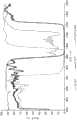
图2为示出实施例1的膜的透光态和阻光态透射光谱的图。FIG. 2 is a graph showing the transmission spectra of the film of Example 1 in the light-transmitting state and the light-blocking state.
图3为示出实施例1的膜的层剖面的图。FIG. 3 is a view showing a layer cross section of a film of Example 1. FIG.
具体实施方式Detailed ways
多层光学膜,即至少部分地通过具有不同折射率的微层的布置提供期望的透射和/或反射特性的膜是已知的。众所周知,此类多层光学膜通过在真空室中将一系列无机材料以光学薄层(“微层”)的形式沉积于基材上而制成。无机多层光学膜描述在教科书中,例如H.A.Macleod,薄膜光学滤波器,第二版,麦克米伦出版公司(1986年)(H.A.Macleod,Thin-Film Optical Filters,2nd Ed.,Macmillan Publishing Co.(1986))和A.Thelan,光学干涉滤波器的设计,麦格劳希尔公司(1989年)(A.Thelan,Design of OpticalInterference Filters,McGraw-Hill,Inc.(1989))。Multilayer optical films, ie films that provide desired transmission and/or reflection properties at least in part through the arrangement of microlayers with different refractive indices, are known. It is well known that such multilayer optical films are produced by depositing a series of inorganic materials in optically thin layers ("microlayers") on a substrate in a vacuum chamber. Inorganic multilayer optical films are described in textbooks such as H.A. Macleod, Thin-Film Optical Filters, Second Edition, Macmillan Publishing Company (1986) (H.A. Macleod, Thin-Film Optical Filters, 2nd Ed., Macmillan Publishing Co. (1986)) and A. Thelan, Design of Optical Interference Filters, McGraw-Hill, Inc. (1989) (A. Thelan, Design of Optical Interference Filters, McGraw-Hill, Inc. (1989)).
也已通过共挤出交替的聚合物层展示多层光学膜。参见例如美国专利3610729(Rogers)、4446305(Rogers等人)、4540623(Im等人)、5448404(Schrenk等人)以及5882774(Jonza等人)。在这些种聚合物多层光学膜中,聚合物材料主要或专门用于各个层的制备中。此类膜适合高产量制造工艺,并且可制成大型片材和卷材。Multilayer optical films have also been demonstrated by coextrusion of alternating polymer layers. See, eg, US Patents 3,610,729 (Rogers), 4,446,305 (Rogers et al.), 4,540,623 (Im et al.), 5,448,404 (Schrenk et al.), and 5,882,774 (Jonza et al.). In these kinds of polymeric multilayer optical films, polymeric materials are used primarily or exclusively in the preparation of the individual layers. These films are suitable for high-volume manufacturing processes and are available in large sheets and rolls.
多层光学膜包括具有不同折射率特征的各个微层,使得一些光在相邻微层之间的界面处被反射。微层是足够薄的,使得在多个界面处反射的光经受相长干涉或相消干涉作用,以便赋予多层光学膜期望的反射或透射特性。对于被设计成反射处于紫外波长、可见波长或近红外波长的光的多层光学膜,每个微层通常具有小于约1μm的光学厚度(物理厚度乘以折射率)。也可包括更厚的层,诸如在多层光学膜的外表面处的表层,或设置在多层光学膜内、分离微层的连贯分组(在本文称为“层组”)的保护性边界层(PBL)。Multilayer optical films include individual microlayers with different refractive index characteristics such that some light is reflected at interfaces between adjacent microlayers. The microlayers are sufficiently thin such that light reflected at multiple interfaces undergoes constructive or destructive interference in order to impart the desired reflective or transmissive properties to the multilayer optical film. For multilayer optical films designed to reflect light at ultraviolet, visible, or near-infrared wavelengths, each microlayer typically has an optical thickness (physical thickness times refractive index) of less than about 1 μm. Thicker layers may also be included, such as skin layers at the outer surfaces of the multilayer optical film, or protective boundaries disposed within the multilayer optical film that separate coherent groupings of microlayers (referred to herein as "layer packs") layer (PBL).
对于偏振应用,例如对于反射偏振器,光学层中的至少一些光学层是使用双折射聚合物形成的,其中聚合物的折射率沿聚合物的正交笛卡尔轴具有不同值。通常,双折射聚合物微层具有由层平面的法线(z轴)定义的正交笛卡尔轴,其中x轴和y轴位于层平面内。双折射聚合物也可用于非偏振应用中。For polarizing applications, such as reflective polarizers, at least some of the optical layers are formed using birefringent polymers in which the polymers have different values of refractive index along orthogonal Cartesian axes of the polymers. Typically, birefringent polymer microlayers have orthogonal Cartesian axes defined by the normal to the layer plane (z-axis), with the x- and y-axes lying within the layer plane. Birefringent polymers can also be used in non-polarizing applications.
在一些情况下,微层具有对应于1/4波长叠堆的厚度和折射率值,即布置于光学重复单元或单元格中,每个光学重复单元或单元格具有相等光学厚度的两个相邻微层(f比率=50%),此类光学重复单元通过相长干涉有效地反射光,被反射光的波长λ是光学重复单元的总体光学厚度的两倍。其它层布置也是已知的,诸如具有f比率不同于50%的双微层光学重复单元的多层光学膜,或光学重复单元包括多于两个微层的膜。可以配置这些光学重复单元设计以减少或增加某些更高阶反射。参见例如美国专利5360659号(Arends等人)和美国专利5103337号(Schrenk等人)。沿膜厚度轴(例如z轴)的厚度梯度可用于提供加宽的反射谱带,诸如在人的整个可视区域内延伸并进入近红外区的反射谱带,使得当谱带以斜入射角转移到较短波长时,微层叠堆继续在整个可见光谱内反射。通过调整厚度梯度来锐化谱带边缘(即高反射与高透射之间的波长过渡)在美国专利6157490(Wheatley等人)中有所讨论。In some cases, the microlayers have thicknesses and refractive index values corresponding to 1/4 wavelength stacks, i.e., arranged in optical repeating units or cells, each optical repeating unit or cell having two phases of equal optical thickness. Adjacent to the microlayer (f ratio = 50%), such optical repeat units efficiently reflect light by constructive interference at a wavelength λ that is twice the overall optical thickness of the optical repeat unit. Other layer arrangements are also known, such as multilayer optical films with dual microlayer optical repeat units having an f-ratio different from 50%, or films in which the optical repeat unit comprises more than two microlayers. These optical repeat unit designs can be configured to reduce or increase certain higher order reflections. See, eg, US Patent No. 5,360,659 (Arends et al.) and US Patent No. 5,103,337 (Schrenk et al.). A thickness gradient along a film thickness axis (e.g., the z-axis) can be used to provide a broadened reflection band, such as one that extends throughout the human visual field and into the near-infrared region, such that when the band is viewed at an oblique angle of incidence When shifting to shorter wavelengths, the microlayer stack continues to reflect throughout the visible spectrum. Sharpening of band edges (ie, the wavelength transition between high reflection and high transmission) by adjusting thickness gradients is discussed in US Patent 6,157,490 (Wheatley et al.).
多层光学膜以及相关设计和构造的另外细节在美国专利5882774(Jonza等人)和6531230(Weber等人)、PCT公布WO 95/17303(Ouderkirk等人)和WO 99/39224(Ouderkirk等人)、以及标题为“多层聚合物反射镜中的巨大双折射光学器件”,科学,第287卷,2000年3月(Weber等人)(“Giant Birefringent Optics in Multilayer Polymer Mirrors”,Science,Vol.287,March 2000(Weber et al.))的公布中有所讨论。多层光学膜和相关制品可包括针对其光学特性、机械特性和/或化学特性而选择的附加层和涂层。例如,在膜的入射侧可添加UV吸收层以保护部件免于UV光引起的降解。使用可UV固化的丙烯酸酯粘合剂或其它合适的材料可以将多层光学膜附接到机械增强层。此类增强层可包含诸如PET或聚碳酸酯的聚合物,并且也可包括例如通过使用小珠或棱镜提供诸如光漫射或光准直的光学功能的结构化表面。附加层和涂层也可包括抗乱涂层、抗撕裂层和硬化剂。参见例如美国专利6368699(Gilbert等人)。用于制备多层光学膜的方法和装置在美国专利6783349(Neavin等人)中有所讨论。Additional details of multilayer optical films and related design and construction are found in US Pat. , and entitled "Giant Birefringent Optics in Multilayer Polymer Mirrors", Science, Vol. 287, March 2000 (Weber et al.) ("Giant Birefringent Optics in Multilayer Polymer Mirrors", Science, Vol. 287, discussed in the publication March 2000 (Weber et al.). Multilayer optical films and related articles can include additional layers and coatings selected for their optical, mechanical, and/or chemical properties. For example, a UV absorbing layer can be added on the incident side of the film to protect the part from degradation caused by UV light. The multilayer optical film can be attached to the mechanical reinforcement layer using a UV curable acrylate adhesive or other suitable material. Such reinforcement layers may comprise polymers such as PET or polycarbonate, and may also comprise structured surfaces providing optical functions such as light diffusion or light collimation, eg by using beads or prisms. Additional layers and coatings may also include anti-scratch coatings, anti-tear layers and hardeners. See, eg, US Patent 6,368,699 (Gilbert et al.). Methods and apparatus for making multilayer optical films are discussed in US Patent 6,783,349 (Neavin et al.).
多层光学膜的反射特性和透射特性取决于各自微层的折射率以及微层的厚度和厚度分布。每个微层(至少在膜的局部位置处)可以通过面内折射率nx、ny以及与膜的厚度轴相关联的折射率nz来表征。这些折射率分别表示所讨论的材料对于沿相互正交的x轴、y轴和z轴偏振的光的折射率。为便于在本专利申请中说明,除非另外指明,否则假设x轴、y轴和z轴为适用于多层光学膜上任何感兴趣点的局部笛卡尔坐标,其中微层平行于x-y平面延伸,并且其中x轴在膜平面内取向以最大化Δnx的量值。因此,Δny的量值可以等于或小于(但不大于)Δnx的量值。此外,选择哪个材料层(以开始计算差值Δnx、Δny、Δnz)由需要Δnx为非负值来决定。换句话说,形成界面的两层之间的折射率差值均为Δnj=n1j–n2j,其中j=x、y或z,并且其中选择层标号1、2,使得n1x≥n2x,即Δnx≥0。The reflective and transmissive properties of multilayer optical films depend on the refractive index of the respective microlayers as well as the thickness and thickness distribution of the microlayers. Each microlayer (at least at local locations of the film) can be characterized by the in-plane refractive indexnx ,ny , and the refractive indexnz associated with the thickness axis of the film. These indices of refraction represent, respectively, the indices of refraction of the material in question for light polarized along mutually orthogonal x-, y-, and z-axes. For ease of description in this patent application, unless otherwise indicated, the x-, y-, and z-axes are assumed to be local Cartesian coordinates applicable to any point of interest on a multilayer optical film, where the microlayers extend parallel to the xy plane, and where the x-axis is oriented in the plane of the film to maximize the magnitude of Δnx . Thus, the magnitude of Δny may be equal to or less than (but not greater than) the magnitude of Δnx . Furthermore, which material layer to choose (to start calculating the differences Δnx ,Δny , Δnz ) is determined by the need for Δnx to be non-negative. In other words, the refractive index difference between the two layers forming the interface is Δnj =n1j –n2j , where j=x, y or z, and where layer numbers 1, 2 are chosen such that n1x ≥ n2x , that is, Δnx ≥ 0.
在实践中,折射率是通过审慎的材料选择和加工条件来控制的。常规的多层膜通过以下方式制备:将大量(例如数十或数百)层的两种交替的聚合物A、聚合物B共挤出,可能接着将多层挤出物穿过一个或多个倍增模头,并且然后对挤出物进行拉伸或者以其它方式将挤出物取向以形成最终的膜。所得膜通常由许多—数百个或上百个—单独的微层构成,这些微层的厚度和折射率被调整以在期望光谱区域(诸如可见光区或近红外光区)中提供一个或多个反射谱带。为了在适当层数下获得所需反射率,相邻微层通常表现出对于沿x轴偏振的光为至少0.04的折射率差值(Δnx)。在一些实施方案中,选择材料,使得对于沿x轴偏振的光的折射率差值在进行取向之后尽可能高。如果期望对两种正交偏振的反射率,那么也可以将相邻微层制成表现出对于沿y轴偏振的光为至少0.04的折射率差值(Δny)。In practice, the refractive index is controlled through judicious material selection and processing conditions. Conventional multilayer films are prepared by coextruding a large number (eg tens or hundreds) of layers of two alternating polymers A, polymer B, possibly followed by passing the multilayer extrudate through one or more multiplier die, and then stretch or otherwise orient the extrudate to form the final film. The resulting film is typically composed of many—hundreds or hundreds—of individual microlayers whose thickness and refractive index are tuned to provide one or more a reflection band. In order to obtain the desired reflectivity at an appropriate number of layers, adjacent microlayers typically exhibit a difference in refractive index (Δnx ) of at least 0.04 for light polarized along the x-axis. In some embodiments, the materials are selected such that the difference in refractive index for light polarized along the x-axis is as high as possible after orientation. Adjacent microlayers can also be made to exhibit a difference in refractive index (Δny ) of at least 0.04 for light polarized along the y-axis if reflectivity for two orthogonal polarizations is desired.
除其它事项之外,以上引用的‘774(Jonza等人)专利描述了对于沿z轴偏振的光可如何调整相邻微层之间的折射率差值(Δnz)以实现对斜入射光的p偏振分量的期望反射率特性。为了保持处于斜入射角的p偏振光的高反射率,可将微层之间的z轴折射率失配Δnz控制成基本上小于面内折射率差值Δnx的最大值,使得Δnz≤0.5*Δnx,或Δnz≤0.25*Δnx。量值为零或几乎为零的z轴线折射率失配产生了微层之间的这样的界面,该界面对p偏振光的反射率为作为入射角的函数的常数或几乎为常数。此外,可以控制z轴折射率失配Δnz以具有相比于面内折射率差值Δnx相反的极性,即Δnz<0。该条件会产生其反射率对于p偏振光随入射角增加而增大的界面,对于s偏振光的情形也一样。Among other things, the above-cited '774 (Jonza et al.) patent describes how, for light polarized along the z-axis, the difference in refractive index (Δnz ) between adjacent microlayers can be adjusted to achieve oblique incident light The expected reflectivity characteristics of the p-polarized component of . To maintain high reflectivity for p-polarized light at oblique incidence angles, the z-axis refractive index mismatch Δnz between microlayers can be controlled to be substantially smaller than the maximum value of the in-plane refractive index difference Δnx such that Δnz ≤0.5*Δnx , or Δnz ≤0.25*Δnx . A z-axis refractive index mismatch of zero or nearly zero magnitude produces an interface between microlayers whose reflectivity for p-polarized light is constant or nearly constant as a function of angle of incidence. Furthermore, the z-axis refractive index mismatch Δnz can be controlled to have an opposite polarity compared to the in-plane refractive index difference Δnx , ie Δnz <0. This condition produces an interface whose reflectivity increases for p-polarized light with increasing angle of incidence, as is the case for s-polarized light.
‘774(Jonza等人)专利也讨论了与配置为偏振器的多层光学膜(称为多层反射或反射性偏振器)相关的某些设计考虑。在许多应用中,理想的反射偏振器沿一个轴(“消光”或“阻光”轴)具有高反射率,并且沿另一个轴(“透射”或“透光”轴)具有零反射率。为了本专利申请的目的,其偏振态基本上与透光轴或透射轴对准的光被称为透过光,并且其偏振状态基本上与阻光轴或消光轴对准的光被称为阻光。除非另外指明,以60°入射角的透过光在p偏振的透过光中测量。如果沿透射轴出现一些反射率,则偏振器在偏离垂直角度处的效率可能会降低;并且如果对于多个波长来说反射率不同,则可以将颜色引入至透射光中。此外,在一些多层系统中,可能无法准确匹配两个y轴折射率和两个z轴折射率,并且当z轴折射率失配时,对面内折射率n1y和n2y而言,可能期望产生轻微的失配。具体地,通过布置y轴折射率失配以具有与z轴折射率失配相同的符号,在微层界面处产生Brewster效应,以最小化沿多层反射偏振器的透射轴的偏轴反射率,并因此最小化偏轴颜色。The '774 (Jonza et al.) patent also discusses certain design considerations associated with multilayer optical films configured as polarizers (referred to as multilayer reflective or reflective polarizers). In many applications, an ideal reflective polarizer has high reflectivity along one axis (the "extinction" or "blocking" axis) and zero reflectance along the other axis (the "transmission" or "transmission" axis). For the purposes of this patent application, light whose polarization state is substantially aligned with the pass axis or transmission axis is referred to as transmitted light, and light whose polarization state is substantially aligned with the block or extinction axis is referred to as Light blocking. Transmitted light at an incident angle of 60° is measured in p-polarized transmitted light unless otherwise specified. If some reflectivity occurs along the transmission axis, the efficiency of the polarizer at off-perpendicular angles may be reduced; and if the reflectivity is different for multiple wavelengths, color may be introduced into the transmitted light. In addition, in some multilayer systems, it may not be possible to exactly match the two y-axis indices and the two z-axis indices, and when the z-axis indices are mismatched, it may be desirable for the in-plane indices n1y and n2y to yield slight mismatch. Specifically, by arranging the y-axis index mismatch to have the same sign as the z-axis index mismatch, the Brewster effect is generated at the microlayer interface to minimize the off-axis reflectance along the transmission axis of the multilayer reflective polarizer , and thus minimize off-axis colors.
在‘774(Jonza等人)中讨论的另一个设计考虑涉及在多层反射偏振器空气界面处的表面反射。除非偏振器在两侧均层合至现有玻璃部件或具有透明光学粘合剂的另一个现有膜,否则这种表面反射将减少光学系统中所需偏振的光的透射。因此,在一些情况下,将防反射(AR)涂层添加至反射偏振器上是有用的。Another design consideration discussed in '774 (Jonza et al.) concerns surface reflection at the air interface of a multilayer reflective polarizer. Unless the polarizer is laminated on both sides to an existing glass part or another existing film with a clear optical adhesive, this surface reflection will reduce the transmission of light of the desired polarization in the optical system. Therefore, in some cases it is useful to add an anti-reflection (AR) coating to a reflective polarizer.
诸如液晶显示器之类的视觉显示系统中常使用反射偏振器。目前可见于诸如移动电话、计算机(包括平板电脑、笔记本电脑和小型笔记本计算机)和一些平板电视之类的多种电子装置中的这些系统使用由伸展区域背光从背后提供照明的液晶(LC)面板。将反射偏振器放置在在背光源上方或者以其它方式结合到背光源中,以将背光源发出的能够被LC面板使用的偏振态的光透射至LC面板。不能被LC面板使用的垂直偏振态的光被反射回背光源,并在背光源内最终反射回LC面板,并且至少部分地转化为可用的偏振态,从而“循环”通常会损失的光,并提高显示器的所得亮度和总效率。Reflective polarizers are commonly used in visual display systems such as liquid crystal displays. These systems, currently found in a variety of electronic devices such as mobile phones, computers (including tablets, laptops, and notebooks), and some flat-panel televisions, use liquid crystal (LC) panels backlit by an extended area backlight . A reflective polarizer is placed over or otherwise incorporated into the backlight to transmit light from the backlight to the LC panel in a polarization state that can be used by the LC panel. Light in a vertically polarized state that cannot be used by the LC panel is reflected back to the backlight, where it is eventually reflected back to the LC panel, and is at least partially converted to a usable polarization state, thereby "recycling" light that would normally be lost, and improving The resulting brightness and overall efficiency of the display.
在某些实施方案中,多层反射偏振器可用于汽车应用中。例如,多层反射偏振器可用于车辆挡风玻璃、侧窗或另一种在其它方面透明或半透明的表面(诸如工业窗、建筑窗、天窗、房间窗等)的至少一部分上或附近。该应用与传统液晶显示器应用显著不同,因为出于安全原因,驾驶员应该仍然能够通过多层反射偏振器观察道路或周围环境,或者具有穿过表面的最小中断视图。此外,其它驾驶员或观察者不应因驾驶员的挡风玻璃或另一表面的明亮反射而发生目眩或视力受损。高反射率(对于一种偏振状态)、高性能的传统反射偏振器将不满足这些要求。In certain embodiments, multilayer reflective polarizers are useful in automotive applications. For example, a multilayer reflective polarizer may be used on or near at least a portion of a vehicle windshield, side window, or another otherwise transparent or translucent surface such as an industrial window, architectural window, skylight, room window, etc. This application differs significantly from traditional LCD applications because for safety reasons the driver should still be able to view the road or surroundings through the multilayer reflective polarizer, or have a minimally interrupted view through the surface. Additionally, other drivers or observers should not be dazzled or visually impaired by bright reflections from the driver's windshield or another surface. High reflectivity (for one polarization state), high performance conventional reflective polarizers will not meet these requirements.
此外,先前已知的反射偏振器对汽车和玻璃组件以及一般用途中涉及的加工和环境暴露敏感。例如,反射偏振器可与聚乙烯醇缩丁醛(PVB)一起使用、用PVB加工、或层合至PVB,以实现安全的玻璃抗破碎性。在用于形成层合挡风玻璃部件的高温加工下,具有基于PVB的材料的部件可穿透并降解常规制造和设计的反射偏振器。作为另一示例,用作许多市售反射偏振器中的聚合物和/或共聚物的聚萘二甲酸乙二醇酯,特别是包括NDC(2,6-萘二甲酸二甲酯)的聚萘二甲酸乙二醇酯(PEN),在暴露于紫外线辐射时会发黄。车辆或户外暴露(例如,对于外部窗)环境提供对太阳辐射的充分暴露,这可随时间推移而使反射偏振器降解。在此类环境中,也可能发生自发的大尺寸结晶,从而在反射偏振器中发展出雾度。在一些实施方案中,本文所述的反射偏振器不包含聚萘二甲酸乙二醇酯。在一些实施方案中,本文所述的反射偏振器不包含萘-2,6-二羧酸。在一些实施方案中,在550nm处测量时,本文所述的反射偏振器在任何层中沿任何方向均不具有大于1.7的折射率。Furthermore, previously known reflective polarizers are sensitive to processing and environmental exposure involved in automotive and glass assemblies as well as general use. For example, reflective polarizers can be used with polyvinyl butyral (PVB), processed with PVB, or laminated to PVB for safe glass shatter resistance. Under the high temperature processing used to form laminated windshield components, components with PVB-based materials can penetrate and degrade conventionally manufactured and designed reflective polarizers. As another example, polyethylene naphthalate, particularly polyethylene naphthalate including NDC (dimethyl 2,6-naphthalate), is used as a polymer and/or copolymer in many commercially available reflective polarizers. Ethylene naphthalate (PEN), which turns yellow when exposed to UV radiation. Vehicle or outdoor exposure (eg, for exterior windows) environments provide sufficient exposure to solar radiation, which can degrade the reflective polarizer over time. In such environments, spontaneous large-size crystallization can also occur, developing haze in reflective polarizers. In some embodiments, the reflective polarizers described herein do not comprise polyethylene naphthalate. In some embodiments, the reflective polarizers described herein do not include naphthalene-2,6-dicarboxylic acid. In some embodiments, the reflective polarizers described herein do not have an index of refraction greater than 1.7 in any layer and in any direction when measured at 550 nm.
多层光学膜通常由两种不同聚合物的交替层形成。一个层是当被取向时能够发展出双折射的层。由于几乎所有用于形成多层光学膜的聚合物在被拉伸时均折射率增大,因此该层通常也被称为高折射率层(或“高折射率光学器件”或HIO)。交替的聚合物层中的另一层通常为各向同性层,等于或小于高折射率层的折射率。为此,该层通常被称为低折射率层(或“低折射率光学器件”或LIO)。通常,高折射率层为结晶或半结晶的,而低折射率层为无定形的。这至少基于以下观念:为了获得足够高的阻光轴反射率(基于高折射率层与低折射率层之间沿某个面内方向的失配)和足够低的透光轴反射率(基于高折射率层与低折射率层之间沿第二正交的面内方向的匹配),将需要无定形材料。Multilayer optical films are typically formed from alternating layers of two different polymers. A layer is a layer capable of developing birefringence when oriented. Since nearly all polymers used to form multilayer optical films have an index of refraction increase when stretched, this layer is also often referred to as a high index layer (or "high index optics" or HIO). The other of the alternating polymer layers is typically an isotropic layer, equal to or less than the refractive index of the high index layer. For this reason, this layer is often referred to as a low index layer (or "low index optics" or LIO). Typically, the high refractive index layer is crystalline or semi-crystalline, while the low refractive index layer is amorphous. This is based at least on the idea that in order to obtain a sufficiently high reflectance of the blocking axis (based on the mismatch between the high-index layer and the low-index layer along a certain in-plane direction) and a sufficiently low reflectance of the pass axis (based on Matching between the high index layer and the low index layer along the second orthogonal in-plane direction) would require an amorphous material.
现已令人惊讶地发现,具有高折射率层和低折射率层两者的多层反射偏振器尤其适用于这些汽车应用,所述高折射率层和低折射率层具有由于聚对苯二甲酸乙二醇酯的低拉伸温度而在拉伸期间发展出的一定程度的结晶度。另外,已经令人惊讶地发现,其中高折射率光学器件和低折射率光学器件均通过拉伸发展出不对称折射率的多层反射偏振器可用于汽车应用中。在一些实施方案中,各个高折射率层和低折射率层均可发展出或具有为至少0.04的面内双折射率。在一些实施方案中,沿一个面内方向,高折射率层与低折射率层之间的差值可为至少0.04,但沿正交的第二面内方向,差值可小于0.04。在某些中间拉伸步骤期间,某些多层光学膜可具有类似的双折射特性;然而,随后使这些膜经受热定形处理,该热定形处理使这些层中的至少一个层(通常为低折射率层或各向同性层)中的双折射最小化,从而使阻光轴(拉伸轴)反射率最大化,这意味着最终膜(即,卷筒形式的膜或具有至少四个边缘的经转换的膜)不表现出这些特性。It has now surprisingly been found that multilayer reflective polarizers having both high and low refractive index layers which have the The low stretching temperature of ethylene glycol formate develops some degree of crystallinity during stretching. Additionally, it has surprisingly been found that multilayer reflective polarizers in which both the high index optic and the low index optic develop an asymmetric index of refraction by stretching can be used in automotive applications. In some embodiments, each of the high and low index layers can develop or have an in-plane birefringence of at least 0.04. In some embodiments, the difference between the high index layer and the low index layer can be at least 0.04 along one in-plane direction, but less than 0.04 along a second, orthogonal in-plane direction. During certain intermediate stretching steps, certain multilayer optical films may have similar birefringent properties; Birefringence in the refractive index layer or isotropic layer) is minimized to maximize the block axis (stretch axis) reflectance, which means that the final film (i.e., a film in roll form or with at least four edges converted membranes) do not exhibit these properties.
在一些实施方案中,高折射率层被选择为聚对苯二甲酸乙二醇酯(PET),并且低折射率层被选择为聚对苯二甲酸乙二醇酯与用作二醇改性剂的环己烷二甲醇(PETG,诸如可购自田纳西州诺克斯维尔的伊士曼化学公司(Eastman Chemicals,Knoxville,Tenn.))的共聚酯。在一些实施方案中,高折射率层被选择为PET,并且低折射率层被选择为PETG和PCTG(还是聚对苯二甲酸乙二醇酯与用作二醇改性剂的环己烷二甲醇,但是具有两倍于PETG的改性剂,可购自田纳西州诺克斯维尔的伊士曼化学公司)的50:50共混物。在一些实施方案中,高折射率层被选择为PET,并且低折射率层被选择为PETG、PCTG和“80:20”共聚酯的33:33:33共混物,该共聚酯具有40mol%的对苯二甲酸、10mol%的间苯二甲酸、49.75mol%的乙二醇和0.25mol%的三甲基丙醇。其它共聚酯可用作本文所述的低折射率层或用于本文所述的低折射率层中。In some embodiments, the high refractive index layer is selected to be polyethylene terephthalate (PET), and the low refractive index layer is selected to be polyethylene terephthalate and used as a glycol modification Cyclohexanedimethanol (PETG, such as copolyesters available from Eastman Chemicals, Knoxville, Tenn.) of Knoxville, Tennessee. In some embodiments, the high index layer is chosen to be PET and the low index layer is chosen to be PETG and PCTG (again polyethylene terephthalate with cyclohexane diol used as diol modifier). Methanol, but with twice the modifier of PETG, is available as a 50:50 blend from Eastman Chemical Company, Knoxville, TN). In some embodiments, the high index layer is selected to be PET and the low index layer is selected to be a 33:33:33 blend of PETG, PCTG, and an "80:20" copolyester having 40 mol% terephthalic acid, 10 mol% isophthalic acid, 49.75 mol% ethylene glycol and 0.25 mol% trimethylpropanol. Other copolyesters can be used as or in the low refractive index layers described herein.
包含诸如上述示例性组的材料的反射偏振器令人惊讶地在高温暴露之后表现出对雾度的更好抑制,这是由于结晶是在加工期间逐渐发展的,而不是在暴露于辐射或热期间自发地(伴随有较大的结晶位点)发展的。此外,使用本文所例示的结晶材料组合时,外表和外观问题(诸如微褶皱或分层)似乎显著较不频繁地发生。Reflective polarizers comprising materials such as the exemplary group described above surprisingly exhibit better suppression of haze after high temperature exposure due to the gradual development of crystallization during processing rather than after exposure to radiation or heat Spontaneously (with larger crystalline sites) developed during this period. Furthermore, appearance and appearance issues, such as micro-wrinkling or delamination, appear to occur significantly less frequently when using the combinations of crystalline materials exemplified herein.
收缩率,尤其是沿最大拉伸方向的收缩率可大于常规反射偏振器。然而,收缩量可通过热定形步骤控制,并且在汽车的制造和组装过程中,需要一定量的收缩。Shrinkage, especially along the direction of maximum stretch, can be greater than conventional reflective polarizers. However, the amount of shrinkage can be controlled by the heat setting step, and during the manufacturing and assembly of automobiles, a certain amount of shrinkage is required.
在一些实施方案中,如本文所述的多层光学膜包括同时形成的具有不同特征光学光谱的两个不同的光分组。图1为光学膜的侧正视横截面。光学膜100包括反射偏振器部分110和红外反射器部分120,该反射偏振器部分和红外反射器部分由保护性边界层130分开并且包括表层140。反射偏振器部分包括交替的第一聚合物层112和第二聚合物层114,并且红外反射器部分包括交替的第三聚合物层122和第四聚合物层124。反射偏振器部分与红外反射器部分之间不存在粘合剂。相反,这两个部分,连同这两个部分之间的任选保护性边界层130和保护交替的光学层免受挤出和辊接触的加工和剪切力的任选表层140,同时被共挤出和取向或以其它方式形成。In some embodiments, a multilayer optical film as described herein includes two different optical packets formed simultaneously having different characteristic optical spectra. Figure 1 is a side elevational cross-section of an optical film.
在包括拉伸或取向的典型成膜过程中,由此制得的光学膜的光轴将由于拉伸过程中的不对称性而在横维维度上变化。变化率将取决于加工条件。对于将包括层合至红外反射器的反射偏振器部分的膜,这些光轴可能不是精确对准的,或甚至不是非常紧密对准的,因为膜的各部分可来自不同的幅材位置或只是可能已经经受不同的加工条件。有利地,具有同时形成(挤出和拉伸)的部分的膜将必然具有其光轴的优异对准。During a typical film formation process involving stretching or orientation, the optical axis of the resulting optical film will vary in the cross-web dimension due to the asymmetry in the stretching process. The rate of change will depend on processing conditions. For a film that will include a reflective polarizer portion laminated to an infrared reflector, these optical axes may not be precisely aligned, or even very closely aligned, as portions of the film may come from different web positions or simply May have been subjected to different processing conditions. Advantageously, a film with simultaneously formed (extruded and stretched) parts will necessarily have excellent alignment of its optical axes.
令人惊讶地,使用合适的材料和加工条件,本文所述的膜可具有第一部分和第二部分,该第一部分表现出反射偏振器特性(偏振敏感性更高的反射:反射比具有正交偏振的光更多的具有第一偏振的光),该第二部分表现出红外反射器特性(偏振敏感性更低的反射;更像镜子:以类似水平反射偏振光或非偏振光)。通常,这些膜将利用不同的拉伸条件,例如,反射偏振器主要在单个方向上拉伸,而相比之下红外反射器则在两个正交方向上几乎均匀地拉伸。在一些实施方案中,主要或仅在横维方向上拉伸膜。Surprisingly, using suitable materials and processing conditions, the films described herein can have a first portion and a second portion, the first portion exhibiting reflective polarizer properties (higher polarization sensitive reflection: reflectance with orthogonal polarized light more light with the first polarization), this second part exhibits infrared reflector properties (reflection less polarization sensitive; more like a mirror: reflects polarized or unpolarized light at similar levels). Typically, these films will utilize different stretching conditions, for example, reflective polarizers are stretched primarily in a single direction, while infrared reflectors are stretched almost uniformly in two orthogonal directions, for example. In some embodiments, the film is stretched primarily or only in the crossweb direction.
另外,在厚度方向上缺乏对称性的典型取向的多层膜一旦从张力释放(例如,在转换之后)就具有卷曲的趋势。这可能是由于组分材料之间的收缩、热膨胀和吸湿性膨胀的差异。在膜的下游加工或处理中,膜卷曲可为显著的问题。例如,如果多层膜的切片是要切割的并且用粘合剂(诸如PVB)层合至玻璃、塑料、或夹在两片玻璃或塑料之间,则膜卷曲可使处理和加工更慢或更低效,并且还可能降低产率。令人惊讶地,本文所述的膜表现出非常低的卷曲。Additionally, typically oriented multilayer films that lack symmetry in the thickness direction have a tendency to curl upon release from tension (eg, after switching). This may be due to differences in shrinkage, thermal expansion, and hygroscopic expansion between the component materials. Film curling can be a significant problem in downstream processing or handling of films. For example, if slices of multilayer film are to be cut and laminated to glass, plastic, or sandwiched between two sheets of glass or plastic with an adhesive such as PVB, film curl can make handling and processing slower or Less efficient, and possibly lower yields. Surprisingly, the films described herein exhibit very low curl.
在一些实施方案中,反射偏振器部分110包括多个交替的第一聚合物层和第二聚合物层,其中对于至少一个面内方向,反射偏振器部分的各个第一聚合物层和第二聚合物层之间的折射率差值均为至少0.04。在一些实施方案中,对于与该至少一个面内方向正交的第二面内方向,该反射偏振器部分的各个该第一聚合物层和该第二聚合物层之间的折射率差值均小于0.04。在一些实施方案中,红外反射器部分120包括多个交替的第三聚合物层和第四聚合物层。红外反射器部分本身可透射小于50%的在900nm至1200nm范围内取平均的垂直入射的非偏振光。在一些实施方案中,红外反射器部分本身可透射小于40%的在900nm至1200nm范围内取平均的垂直入射的非偏振光。在一些实施方案中,红外反射器部分本身可透射小于30%的在900nm至1200nm范围内取平均的垂直入射的非偏振光。在一些实施方案中,反射偏振器部分和红外反射器部分两者均各自具有多于200个层。In some embodiments,
第一聚合物层112和/或第二聚合物层114中的一者可为或包含与第三聚合物层122和/或第四聚合物层124中的一者相同的材料。在一些实施方案中,对于红外反射器部分,各个第三聚合物层和第四聚合物层之间的折射率差值均为至少0.04。在一些实施方案中,对于两个正交的面内方向,沿第二面内方向,每对第三聚合物层和第四聚合物层之间的折射率差值均大于每对第一聚合物层和第二聚合物层之间的折射率差值。在一些实施方案中,反射偏振器部分110的各个第一聚合物层112和第二聚合物层114均具有至少0.01的面内双折射率。在一些实施方案中,各个第一聚合物层和第二聚合物层均具有至少0.02的面内双折射率。在一些实施方案中,各个第一聚合物层和第二聚合物层均具有至少0.04的面内双折射率。在一些实施方案中,各个第一聚合物层和第二聚合物层均具有至少0.02的面内双折射率。在一些实施方案中,反射偏振器部分110透射大于90%的在900nm至1200nm范围内取平均的垂直入射的非偏振光。One of the
本文所述的光学膜可包括一个或多个附加层或涂层。例如,光学膜100还可包括硬质涂膜。在一些实施方案中,光学膜100还可包括延迟层,诸如四分之一波长延迟器或半波长延迟器。在一些实施方案中,光学膜100可包括光学透明的粘合剂层,并且在一些实施方案中可包括保护性纸材或塑料衬垫。在一些实施方案中,光学膜100可在其任何层中或在例如粘合剂中包含紫外线吸收剂组分。The optical films described herein can include one or more additional layers or coatings. For example, the
当用于汽车挡风玻璃或其它车辆窗上时,光学膜可设置在玻璃的内侧上、玻璃的外侧上或两层层合玻璃之间。在一些实施方案中,玻璃可为弯曲的。在一些实施方案中,当被配置在车辆中时,光学膜可被取向或配置成使得其反射比p偏振可见光更多的s偏振可见光。在一些实施方案中,当被配置在车辆中时,光学膜可被取向或配置成使得其反射比s偏振可见光更多的p偏振可见光。When used on automotive windshields or other vehicle windows, the optical film can be placed on the inside of the glass, on the outside of the glass, or between two layers of laminated glass. In some embodiments, the glass can be curved. In some embodiments, when deployed in a vehicle, the optical film can be oriented or configured such that it reflects more s-polarized visible light than p-polarized visible light. In some embodiments, when deployed in a vehicle, the optical film can be oriented or configured such that it reflects more p-polarized visible light than s-polarized visible light.
就其它材料的耐化学品性和渗透性(边缘侵入)而言,在高折射率层和低折射率层两者中均具有结晶度的反射偏振器也表现更好。Reflective polarizers with crystallinity in both the high and low index layers also perform better in terms of chemical resistance and permeability (edge intrusion) of other materials.
如本文所述的反射偏振器可用于汽车应用,但是也可用于或适用于某些偏振分束器/视图组合器应用。例如,对于某些增强现实显示器或显示设备,所生成的和投影的图像可叠加在佩戴者的观看帧上。可适用于例如汽车应用的平视显示器的优点中的许多优点可为在这些增强现实应用中类似地期望的。Reflective polarizers as described herein may be used in automotive applications, but may also be used or adapted for certain polarizing beam splitter/view combiner applications. For example, with some augmented reality displays or display devices, the generated and projected images may be superimposed on the wearer's viewing frame. Many of the advantages of head-up displays applicable to, for example, automotive applications may be similarly desirable in these augmented reality applications.
实施例Example
本文描述了被设计用于为挡风玻璃显示器和太阳阻挡膜提供组合功能的多层光学膜。因此,单个共挤出膜需要同时提供挡风玻璃显示器的可见光p偏振反射和近红外波长中的强太阳阻隔。为了进行比较,在下表中描述了可购自3M公司(美国明尼苏达州圣保罗)(3M Company(St Paul,MN,USA))的基于弱聚酯/共聚酯的反射偏振器和超透明太阳膜(UCSF)(红外反射器)的物理特性。Multilayer optical films designed to provide combined functionality for windshield displays and solar blocking films are described herein. Therefore, a single coextruded film needs to provide both visible p-polarized reflection of windshield displays and strong solar blocking in the near-infrared wavelengths. For comparison, weak polyester/copolyester based reflective polarizers and ultra clear solar films available from 3M Company (St Paul, MN, USA) are described in the table below (UCSF) (infrared reflector) physical properties.
测试方法Test Methods
纵向(MD)贴标表示该多层光学膜在挤出方向的取向上的结果。横向(TD)表示膜正交于挤出方向的结果。动态力学分析(DMA)是一种测试技术和相关的分析仪器,其测量固体和聚合物熔体的物理特性,报告模量和阻尼,并且可编程以测量力、应力、应变、频率和温度。热机械分析(TMA)是根据温度、时间和所施加的力的样品位移(生长、收缩、移动等)的常见测量。传统上,TMA用于通过在变化的温度下向试样施加恒定的力来表征材料的线性膨胀、玻璃化转变和软化点。The machine direction (MD) label represents the result of the orientation of the multilayer optical film in the extrusion direction. Transverse direction (TD) means the result of the film being perpendicular to the direction of extrusion. Dynamic Mechanical Analysis (DMA) is a testing technique and associated analytical instrumentation that measures the physical properties of solids and polymer melts, reports modulus and damping, and is programmable to measure force, stress, strain, frequency, and temperature. Thermomechanical analysis (TMA) is a common measurement of sample displacement (growth, shrinkage, movement, etc.) as a function of temperature, time, and applied force. Traditionally, TMA has been used to characterize the linear expansion, glass transition, and softening point of materials by applying a constant force to a specimen at varying temperatures.

表1—UCSF的测量特性Table 1—Measurement characteristics of UCSF


表2—单独分组、p偏振反射偏振器的测量特性Table 2—Measured Characteristics of Individually Grouped, P-Polarizing Reflective Polarizers
在表1和表2中,示出了双轴取向的UCSF以及单轴取向的p偏振反射偏振器的热膨胀系数和吸湿膨胀系数。这些特性在反射偏振器的纵向方向上与横向方向相比非常不同,而在双轴膜的两个方向上是非常相似的。In Table 1 and Table 2, the coefficients of thermal expansion and hygroscopic expansion of biaxially oriented UCSFs and uniaxially oriented p-polarization reflective polarizers are shown. These properties are very different in the longitudinal direction of the reflective polarizer compared to the transverse direction, while they are very similar in both directions of the biaxial film.
实施例1Example 1
如下制备多功能挡风玻璃显示器和太阳膜。使用如美国专利9630356号(Neavin等人)中所述的进料区块系统共挤出各有325层的两个独立的多层分组,该进料区块系统包括适用于用于这些实施例的共挤出工艺的表层、拉伸比和拉幅过程。如本文所述,“f比率”是指具有最高光学折射率“A”的组成层的光学厚度与完整光学重复单元(包括层A+B)的光学厚度的比率。Multifunctional windshield displays and solar films were prepared as follows. Two separate multilayer packets of 325 layers each were coextruded using a feedblock system as described in U.S. Patent No. 9,630,356 (Neavin et al.), which includes The surface layer, stretch ratio and tentering process of the co-extrusion process. As used herein, "f-ratio" refers to the ratio of the optical thickness of the constituent layer having the highest optical index of refraction "A" to the optical thickness of the complete optical repeat unit (including layers A+B).
将三种聚合物用于光学层。第一聚合物(第一光学层)是本征粘度为0.72的基于纯化对苯二甲酸(PTA)的聚对苯二甲酸乙二醇酯。第二聚合物(第二光学层)是来自美国田纳西州金斯波特的伊士曼化工公司(Eastman Chemical(Kingsport,TN,USA))的聚对苯二甲酸乙二醇酯(PETG)GN071。第三聚合物为可购自美国俄亥俄州哥伦布市的Plaskolite公司(Plaskolite(Columbus,OH,USA))的CA-24共聚PMMA。第一分组仅使用第一聚合物和第二聚合物,即PET和PETG。第二分组使用第一聚合物和第三聚合物,即PETG和共聚PMMA。第一分组中第一聚合物与第二聚合物的进料速率比被选择为使光学层具有0.50的f比率。第二分组中第一聚合物与第三聚合物的进料速率比被选择为使光学层具有0.496的f比率。用于表层的聚合物为可得自美国田纳西州金斯波特的伊士曼化工公司的EASTAPAK PET 7352。将材料从单独的挤出机中进料到多层共挤出进料区块,在该进料区块中,它们被组装成两个具有325个交替光学层的分组,加上每一侧各有一个较厚的第一光学层保护性边界层,总共654个层。第一光学层材料的表层被添加到特定于该目的的歧管构造,从而生成具有656个层的最终构造。然后,以用于聚酯膜的传统方式将多层熔体通过膜模头浇铸到冷却辊上,在该冷却辊上对其进行淬火。然后在商业规模的线性拉幅机中以约7:1的拉伸比和228℉的温度在拉伸区段中拉伸浇铸料片。热定型区段具有350℉的温度。Three polymers were used for the optical layer. The first polymer (first optical layer) was purified terephthalic acid (PTA) based polyethylene terephthalate with an intrinsic viscosity of 0.72. The second polymer (second optical layer) is polyethylene terephthalate (PETG) GN071 from Eastman Chemical (Kingsport, TN, USA) of Kingsport, TN, USA. . The third polymer was CA-24 copolymerized PMMA available from Plaskolite (Columbus, OH, USA). The first group uses only the first and second polymers, namely PET and PETG. The second group uses a first polymer and a third polymer, namely PETG and co-polymerized PMMA. The feed rate ratio of the first polymer to the second polymer in the first group was chosen such that the optical layer had an f-ratio of 0.50. The feed rate ratio of the first polymer to the third polymer in the second grouping was chosen such that the optical layer had an f-ratio of 0.496. The polymer used for the skin layer was EASTAPAK PET 7352 available from Eastman Chemical Company, Kingsport, Tennessee, USA. Materials are fed from separate extruders into a multilayer coextrusion feedblock where they are assembled into two groupings with 325 alternating optical layers, plus each side Each has a thicker first optical protective boundary layer, for a total of 654 layers. Skin layers of the first optical layer material were added to the purpose-specific manifold construction, resulting in a final construction with 656 layers. The multilayer melt is then cast through a film die onto chill rolls, where it is quenched, in the conventional manner for polyester films. The cast web was then stretched in a stretching zone in a commercial scale linear tenter frame at a stretch ratio of about 7:1 and a temperature of 228°F. The heat setting section has a temperature of 350°F.
在产生该膜之前,存在关于该工艺的流体动力学流动稳定性不足以产生具有平坦界面并且没有层破裂的完全平行的层的问题。然而,这三种聚合物材料的所得材料选择为该共挤出工艺提供相容的流变性,以提供大致平坦的两分组式单轴拉伸的多层光学膜。Before producing this film, there was a problem with the hydrodynamic flow stability of the process being insufficient to produce perfectly parallel layers with flat interfaces and no layer rupture. However, the resulting material selection of these three polymer materials provides a compatible rheology for the coextrusion process to provide a substantially planar two-pack uniaxially stretched multilayer optical film.
将实施例1的多层膜(无涂层)卷绕在外径为约15英寸的辊上,其中第一分组位于辊的外侧上。在四十九天后,通过切割3英寸乘以3英寸的正方形膜来评估膜的卷曲,其中该膜的一个边缘在MD上并且一个边缘在TD上。该膜来自卷的外部缠绕并且处于膜边缘之间的一半处。将该正方形膜放置在平坦表面上,其中分组1朝下,并且测得拐角中的每个拐角的高度为1.5毫米。MD上的边缘是直的,而TD上的边缘是弯曲的,从而提供了1.5毫米的拐角提升。当使用多层膜产生层合的窗用玻璃时,膜的片材易于处理并且卷曲不是问题。The multilayer film of Example 1 (uncoated) was wound on a roll having an outer diameter of about 15 inches with the first subgroup on the outside of the roll. After forty-nine days, film curl was evaluated by cutting a 3 inch by 3 inch square of film with one edge in MD and one edge in TD. The film comes from the outer wrap of the roll and is halfway between the film edges. The square film was placed on a flat surface with Group 1 facing down, and the height of each of the corners measured 1.5 millimeters. The edges on the MD are straight, while those on the TD are curved, providing a 1.5mm corner lift. When using multilayer films to produce laminated glazing, sheets of film are easy to handle and curling is not a problem.
如通过原子力显微镜测量的层厚度剖面在图3中示出。该曲线示出了每个325层分组中的单独层的厚度。The layer thickness profile as measured by atomic force microscopy is shown in FIG. 3 . The curve shows the thickness of the individual layers in each 325-layer grouping.
光学测试和收缩率测试结果Optical test and shrinkage test results
层剖面、第一聚合物、第二聚合物和第三聚合物材料,以及所选择的工艺条件导致了通过常规光谱仪测量并在图2中示出的所得透光态和阻光态透射光谱。此膜具有如通过电容规测量的约86.9μm的所得物理厚度。The layer profiles, first polymer, second polymer and third polymer materials, and selected process conditions lead to the resulting clear and block state transmission spectra measured by conventional spectrometers and shown in FIG. 2 . This film had a resulting physical thickness of about 86.9 μm as measured by capacitance gauge.
在302℉下测量的收缩率为2.74%MD和2.77%TD,从而为该应用提供了充分的各向同性性能。The shrinkage measured at 302°F was 2.74% MD and 2.77% TD, providing sufficient isotropic properties for this application.
本发明不应被视为限于上述具体实施例和实施方案,因为详细描述此类实施方案是为了便于说明本发明的各个方面。相反,本发明应被理解为涵盖本发明的所有方面,包括落在由所附权利要求书及其等同物所限定的本发明的范围内的各种修改、等同工艺和替代装置。The present invention should not be considered limited to the particular examples and implementations described above, as such embodiments are described in detail for the purpose of illustrating various aspects of the invention. On the contrary, the present invention should be understood to cover all aspects of the present invention, including various modifications, equivalent processes and alternative devices falling within the scope of the present invention as defined by the appended claims and their equivalents.
Claims (30)
Applications Claiming Priority (3)
| Application Number | Priority Date | Filing Date | Title |
|---|---|---|---|
| US201862699459P | 2018-07-17 | 2018-07-17 | |
| US62/699,459 | 2018-07-17 | ||
| PCT/IB2019/055837WO2020016703A2 (en) | 2018-07-17 | 2019-07-09 | Optical film including infrared reflector and multilayer reflective polarizer with crystalline low index layers |
Publications (2)
| Publication Number | Publication Date |
|---|---|
| CN112424657A CN112424657A (en) | 2021-02-26 |
| CN112424657Btrue CN112424657B (en) | 2023-02-28 |
Family
ID=67998508
Family Applications (1)
| Application Number | Title | Priority Date | Filing Date |
|---|---|---|---|
| CN201980047461.5AActiveCN112424657B (en) | 2018-07-17 | 2019-07-09 | Optical film comprising an infrared reflector and a multilayer reflective polarizer with a crystalline low refractive index layer |
Country Status (5)
| Country | Link |
|---|---|
| US (2) | US12253702B2 (en) |
| EP (1) | EP3824332A2 (en) |
| JP (1) | JP7386225B2 (en) |
| CN (1) | CN112424657B (en) |
| WO (1) | WO2020016703A2 (en) |
Families Citing this family (8)
| Publication number | Priority date | Publication date | Assignee | Title |
|---|---|---|---|---|
| JP7512283B2 (en) | 2018-12-18 | 2024-07-08 | スリーエム イノベイティブ プロパティズ カンパニー | Optical Stack |
| WO2020202033A1 (en) | 2019-04-03 | 2020-10-08 | 3M Innovative Properties Company | Optical film and glass laminate |
| EP3963377B1 (en) | 2019-04-30 | 2025-10-15 | 3M Innovative Properties Company | Optical stack |
| US20210263205A1 (en)* | 2020-02-26 | 2021-08-26 | Facebook Technologies, Llc | Polymer thin films having high optical anisotropy |
| CN114980593B (en)* | 2021-02-18 | 2025-07-11 | 北京小米移动软件有限公司 | Optical film, housing, terminal and method for preparing optical film |
| US20240411070A1 (en)* | 2021-12-01 | 2024-12-12 | 3M Innovative Properties Company | Multilayer Optical Film |
| WO2025057084A1 (en)* | 2023-09-15 | 2025-03-20 | 3M Innovative Properties Company | Multilayer optical film and display system including same |
| CN118068609A (en)* | 2024-03-01 | 2024-05-24 | 厦门天马微电子有限公司 | Display module and display device |
Citations (4)
| Publication number | Priority date | Publication date | Assignee | Title |
|---|---|---|---|---|
| US20060232863A1 (en)* | 2005-04-18 | 2006-10-19 | 3M Innovative Properties Company | Thick film multilayer reflector with tailored layer thickness profile |
| US20100124667A1 (en)* | 2008-11-18 | 2010-05-20 | 3M Innovative Properties Company | Isotropic layer of multilayer optical film comprising birefringent thermoplastic polymer |
| CN105593716A (en)* | 2013-09-30 | 2016-05-18 | 3M创新有限公司 | Polymeric multilayer optical film |
| US20170329060A1 (en)* | 2013-11-19 | 2017-11-16 | 3M Innovative Properties Company | Multilayer polymeric reflector |
Family Cites Families (36)
| Publication number | Priority date | Publication date | Assignee | Title |
|---|---|---|---|---|
| US3610729A (en) | 1969-06-18 | 1971-10-05 | Polaroid Corp | Multilayered light polarizer |
| US4446305A (en) | 1981-03-02 | 1984-05-01 | Polaroid Corporation | Optical device including birefringent polymer |
| US4540623A (en) | 1983-10-14 | 1985-09-10 | The Dow Chemical Company | Coextruded multi-layered articles |
| US5103337A (en) | 1990-07-24 | 1992-04-07 | The Dow Chemical Company | Infrared reflective optical interference film |
| JP4001619B2 (en) | 1992-10-29 | 2007-10-31 | スリーエム カンパニー | Moldable reflective multilayer object |
| US5360659A (en)* | 1993-05-24 | 1994-11-01 | The Dow Chemical Company | Two component infrared reflecting film |
| US5882774A (en) | 1993-12-21 | 1999-03-16 | Minnesota Mining And Manufacturing Company | Optical film |
| WO1995017303A1 (en) | 1993-12-21 | 1995-06-29 | Minnesota Mining And Manufacturing Company | Multilayered optical film |
| BR9609314A (en) | 1995-06-26 | 1999-07-06 | Minnesota Mining & Mfg | Multilayer film |
| US6088067A (en)* | 1995-06-26 | 2000-07-11 | 3M Innovative Properties Company | Liquid crystal display projection system using multilayer optical film polarizers |
| US6531230B1 (en) | 1998-01-13 | 2003-03-11 | 3M Innovative Properties Company | Color shifting film |
| US6157490A (en) | 1998-01-13 | 2000-12-05 | 3M Innovative Properties Company | Optical film with sharpened bandedge |
| US6808658B2 (en)* | 1998-01-13 | 2004-10-26 | 3M Innovative Properties Company | Method for making texture multilayer optical films |
| CN1721891A (en) | 1998-01-28 | 2006-01-18 | 美国3M公司 | Infrared interference filter |
| US6952312B2 (en) | 2002-12-31 | 2005-10-04 | 3M Innovative Properties Company | Head-up display with polarized light source and wide-angle p-polarization reflective polarizer |
| US7652736B2 (en)* | 2005-10-25 | 2010-01-26 | 3M Innovative Properties Company | Infrared light reflecting film |
| US7820297B2 (en)* | 2005-12-23 | 2010-10-26 | 3M Innovative Properties Company | Multilayer films including thermoplastic silicone block copolymers |
| US20070236636A1 (en) | 2006-03-31 | 2007-10-11 | Watson Philip E | Contrast ratio enhancement optical stack |
| US8012571B2 (en)* | 2008-05-02 | 2011-09-06 | 3M Innovative Properties Company | Optical film comprising birefringent naphthalate copolyester having branched or cyclic C4-C10 alkyl units |
| EP2310886B1 (en)* | 2008-07-16 | 2012-03-28 | 3M Innovative Properties Company | Multilayer optical film layer comprising blend of methyl methacrylate polymer and styrene acrylonitrile polymer |
| JP5746045B2 (en)* | 2008-12-22 | 2015-07-08 | スリーエム イノベイティブ プロパティズ カンパニー | Internal pattern forming multilayer optical film having a plurality of birefringent layers |
| CN102326100A (en)* | 2008-12-30 | 2012-01-18 | 3M创新有限公司 | Fluoropolymer multilayer optical film and method of making and using same |
| CN102933367B (en) | 2010-05-07 | 2016-06-01 | 3M创新有限公司 | Equipment for the preparation of multilayer polymer films |
| JP2012032454A (en)* | 2010-07-28 | 2012-02-16 | Fujifilm Corp | Infrared reflection film |
| JP5457982B2 (en)* | 2010-08-24 | 2014-04-02 | 富士フイルム株式会社 | Infrared light reflector |
| TWI436096B (en)* | 2010-12-22 | 2014-05-01 | Extend Optronics Corp | Light-uniforming anti-glaring structure and light-emitting device |
| US20130279000A1 (en)* | 2011-01-13 | 2013-10-24 | Toray Industries, Inc. | Far infrared reflecting laminate |
| US9606280B2 (en)* | 2012-05-24 | 2017-03-28 | Extend Optronics Corp. | Method for manufacturing a reflective optical film |
| JP6605328B2 (en) | 2012-07-30 | 2019-11-13 | スリーエム イノベイティブ プロパティズ カンパニー | UV stable assembly including multilayer optical film |
| US9823395B2 (en)* | 2014-10-17 | 2017-11-21 | 3M Innovative Properties Company | Multilayer optical film having overlapping harmonics |
| KR102069024B1 (en)* | 2015-09-03 | 2020-01-22 | 쓰리엠 이노베이티브 프로퍼티즈 컴파니 | Optical system |
| JP6938548B2 (en)* | 2016-06-09 | 2021-09-22 | スリーエム イノベイティブ プロパティズ カンパニー | Optical filter |
| JP7040863B2 (en)* | 2016-09-30 | 2022-03-23 | スリーエム イノベイティブ プロパティズ カンパニー | Visually transparent wideband infrared mirror film |
| JP2021510856A (en) | 2018-01-26 | 2021-04-30 | スリーエム イノベイティブ プロパティズ カンパニー | Multilayer reflective polarizer with a crystalline low index of refraction layer |
| KR20210033993A (en)* | 2018-07-20 | 2021-03-29 | 쓰리엠 이노베이티브 프로퍼티즈 컴파니 | Optical Film Including Polymer Optical Reflector and Discrete Clear Coating |
| JP7512283B2 (en)* | 2018-12-18 | 2024-07-08 | スリーエム イノベイティブ プロパティズ カンパニー | Optical Stack |
- 2019
- 2019-07-09USUS17/260,413patent/US12253702B2/enactiveActive
- 2019-07-09EPEP19772828.0Apatent/EP3824332A2/enactivePending
- 2019-07-09CNCN201980047461.5Apatent/CN112424657B/enactiveActive
- 2019-07-09WOPCT/IB2019/055837patent/WO2020016703A2/ennot_activeCeased
- 2019-07-09JPJP2021502471Apatent/JP7386225B2/enactiveActive
- 2025
- 2025-02-11USUS19/050,597patent/US20250231332A1/enactivePending
Patent Citations (4)
| Publication number | Priority date | Publication date | Assignee | Title |
|---|---|---|---|---|
| US20060232863A1 (en)* | 2005-04-18 | 2006-10-19 | 3M Innovative Properties Company | Thick film multilayer reflector with tailored layer thickness profile |
| US20100124667A1 (en)* | 2008-11-18 | 2010-05-20 | 3M Innovative Properties Company | Isotropic layer of multilayer optical film comprising birefringent thermoplastic polymer |
| CN105593716A (en)* | 2013-09-30 | 2016-05-18 | 3M创新有限公司 | Polymeric multilayer optical film |
| US20170329060A1 (en)* | 2013-11-19 | 2017-11-16 | 3M Innovative Properties Company | Multilayer polymeric reflector |
Also Published As
| Publication number | Publication date |
|---|---|
| EP3824332A2 (en) | 2021-05-26 |
| JP2021530741A (en) | 2021-11-11 |
| WO2020016703A3 (en) | 2020-04-09 |
| US12253702B2 (en) | 2025-03-18 |
| CN112424657A (en) | 2021-02-26 |
| US20250231332A1 (en) | 2025-07-17 |
| WO2020016703A2 (en) | 2020-01-23 |
| JP7386225B2 (en) | 2023-11-24 |
| US20210302637A1 (en) | 2021-09-30 |
Similar Documents
| Publication | Publication Date | Title |
|---|---|---|
| CN112424657B (en) | Optical film comprising an infrared reflector and a multilayer reflective polarizer with a crystalline low refractive index layer | |
| EP0736187B1 (en) | Optical polarizer | |
| EP0735952B1 (en) | Multilayered optical film | |
| JP7512283B2 (en) | Optical Stack | |
| KR102242153B1 (en) | Polymeric multilayer optical film | |
| WO1999036804A1 (en) | Anti-reflective polymer constructions and method for producing same | |
| US20200355859A1 (en) | Multilayer Reflective Polarizer with Crystalline Low Index Layers | |
| JP7745676B2 (en) | Multilayer reflective polarizer with crystalline low refractive index layer |
Legal Events
| Date | Code | Title | Description |
|---|---|---|---|
| PB01 | Publication | ||
| PB01 | Publication | ||
| SE01 | Entry into force of request for substantive examination | ||
| SE01 | Entry into force of request for substantive examination | ||
| GR01 | Patent grant | ||
| GR01 | Patent grant |