CN112406494B - Thermal management system for automobile and thermal management method based on system - Google Patents
Thermal management system for automobile and thermal management method based on systemDownload PDFInfo
- Publication number
- CN112406494B CN112406494BCN201910789070.2ACN201910789070ACN112406494BCN 112406494 BCN112406494 BCN 112406494BCN 201910789070 ACN201910789070 ACN 201910789070ACN 112406494 BCN112406494 BCN 112406494B
- Authority
- CN
- China
- Prior art keywords
- heat exchanger
- plate heat
- valve
- liquid
- liquid cooling
- Prior art date
- Legal status (The legal status is an assumption and is not a legal conclusion. Google has not performed a legal analysis and makes no representation as to the accuracy of the status listed.)
- Active
Links
Images


Classifications
- B—PERFORMING OPERATIONS; TRANSPORTING
- B60—VEHICLES IN GENERAL
- B60H—ARRANGEMENTS OF HEATING, COOLING, VENTILATING OR OTHER AIR-TREATING DEVICES SPECIALLY ADAPTED FOR PASSENGER OR GOODS SPACES OF VEHICLES
- B60H1/00—Heating, cooling or ventilating [HVAC] devices
- B60H1/32—Cooling devices
- B60H1/3204—Cooling devices using compression
- B60H1/3228—Cooling devices using compression characterised by refrigerant circuit configurations
- B60H1/32284—Cooling devices using compression characterised by refrigerant circuit configurations comprising two or more secondary circuits, e.g. at evaporator and condenser side
- B—PERFORMING OPERATIONS; TRANSPORTING
- B60—VEHICLES IN GENERAL
- B60H—ARRANGEMENTS OF HEATING, COOLING, VENTILATING OR OTHER AIR-TREATING DEVICES SPECIALLY ADAPTED FOR PASSENGER OR GOODS SPACES OF VEHICLES
- B60H1/00—Heating, cooling or ventilating [HVAC] devices
- B60H1/00271—HVAC devices specially adapted for particular vehicle parts or components and being connected to the vehicle HVAC unit
- B60H1/00278—HVAC devices specially adapted for particular vehicle parts or components and being connected to the vehicle HVAC unit for the battery
- B—PERFORMING OPERATIONS; TRANSPORTING
- B60—VEHICLES IN GENERAL
- B60H—ARRANGEMENTS OF HEATING, COOLING, VENTILATING OR OTHER AIR-TREATING DEVICES SPECIALLY ADAPTED FOR PASSENGER OR GOODS SPACES OF VEHICLES
- B60H1/00—Heating, cooling or ventilating [HVAC] devices
- B60H1/00357—Air-conditioning arrangements specially adapted for particular vehicles
- B60H1/00385—Air-conditioning arrangements specially adapted for particular vehicles for vehicles having an electrical drive, e.g. hybrid or fuel cell
- B60H1/00392—Air-conditioning arrangements specially adapted for particular vehicles for vehicles having an electrical drive, e.g. hybrid or fuel cell for electric vehicles having only electric drive means
- B—PERFORMING OPERATIONS; TRANSPORTING
- B60—VEHICLES IN GENERAL
- B60H—ARRANGEMENTS OF HEATING, COOLING, VENTILATING OR OTHER AIR-TREATING DEVICES SPECIALLY ADAPTED FOR PASSENGER OR GOODS SPACES OF VEHICLES
- B60H1/00—Heating, cooling or ventilating [HVAC] devices
- B60H1/00485—Valves for air-conditioning devices, e.g. thermostatic valves
- B—PERFORMING OPERATIONS; TRANSPORTING
- B60—VEHICLES IN GENERAL
- B60H—ARRANGEMENTS OF HEATING, COOLING, VENTILATING OR OTHER AIR-TREATING DEVICES SPECIALLY ADAPTED FOR PASSENGER OR GOODS SPACES OF VEHICLES
- B60H1/00—Heating, cooling or ventilating [HVAC] devices
- B60H1/00642—Control systems or circuits; Control members or indication devices for heating, cooling or ventilating devices
- B60H1/00814—Control systems or circuits characterised by their output, for controlling particular components of the heating, cooling or ventilating installation
- B60H1/00878—Control systems or circuits characterised by their output, for controlling particular components of the heating, cooling or ventilating installation the components being temperature regulating devices
- B60H1/00899—Controlling the flow of liquid in a heat pump system
- B60H1/00907—Controlling the flow of liquid in a heat pump system where the flow direction of the refrigerant changes and an evaporator becomes condenser
- B—PERFORMING OPERATIONS; TRANSPORTING
- B60—VEHICLES IN GENERAL
- B60H—ARRANGEMENTS OF HEATING, COOLING, VENTILATING OR OTHER AIR-TREATING DEVICES SPECIALLY ADAPTED FOR PASSENGER OR GOODS SPACES OF VEHICLES
- B60H1/00—Heating, cooling or ventilating [HVAC] devices
- B60H1/22—Heating, cooling or ventilating [HVAC] devices the heat being derived otherwise than from the propulsion plant
- B60H1/2215—Heating, cooling or ventilating [HVAC] devices the heat being derived otherwise than from the propulsion plant the heat being derived from electric heaters
- B60H1/2221—Heating, cooling or ventilating [HVAC] devices the heat being derived otherwise than from the propulsion plant the heat being derived from electric heaters arrangements of electric heaters for heating an intermediate liquid
- B—PERFORMING OPERATIONS; TRANSPORTING
- B60—VEHICLES IN GENERAL
- B60H—ARRANGEMENTS OF HEATING, COOLING, VENTILATING OR OTHER AIR-TREATING DEVICES SPECIALLY ADAPTED FOR PASSENGER OR GOODS SPACES OF VEHICLES
- B60H1/00—Heating, cooling or ventilating [HVAC] devices
- B60H1/32—Cooling devices
- B60H1/3204—Cooling devices using compression
- B60H1/3227—Cooling devices using compression characterised by the arrangement or the type of heat exchanger, e.g. condenser, evaporator
- B—PERFORMING OPERATIONS; TRANSPORTING
- B60—VEHICLES IN GENERAL
- B60H—ARRANGEMENTS OF HEATING, COOLING, VENTILATING OR OTHER AIR-TREATING DEVICES SPECIALLY ADAPTED FOR PASSENGER OR GOODS SPACES OF VEHICLES
- B60H1/00—Heating, cooling or ventilating [HVAC] devices
- B60H1/32—Cooling devices
- B60H1/3204—Cooling devices using compression
- B60H1/3229—Cooling devices using compression characterised by constructional features, e.g. housings, mountings, conversion systems
- B—PERFORMING OPERATIONS; TRANSPORTING
- B60—VEHICLES IN GENERAL
- B60K—ARRANGEMENT OR MOUNTING OF PROPULSION UNITS OR OF TRANSMISSIONS IN VEHICLES; ARRANGEMENT OR MOUNTING OF PLURAL DIVERSE PRIME-MOVERS IN VEHICLES; AUXILIARY DRIVES FOR VEHICLES; INSTRUMENTATION OR DASHBOARDS FOR VEHICLES; ARRANGEMENTS IN CONNECTION WITH COOLING, AIR INTAKE, GAS EXHAUST OR FUEL SUPPLY OF PROPULSION UNITS IN VEHICLES
- B60K1/00—Arrangement or mounting of electrical propulsion units
- B—PERFORMING OPERATIONS; TRANSPORTING
- B60—VEHICLES IN GENERAL
- B60K—ARRANGEMENT OR MOUNTING OF PROPULSION UNITS OR OF TRANSMISSIONS IN VEHICLES; ARRANGEMENT OR MOUNTING OF PLURAL DIVERSE PRIME-MOVERS IN VEHICLES; AUXILIARY DRIVES FOR VEHICLES; INSTRUMENTATION OR DASHBOARDS FOR VEHICLES; ARRANGEMENTS IN CONNECTION WITH COOLING, AIR INTAKE, GAS EXHAUST OR FUEL SUPPLY OF PROPULSION UNITS IN VEHICLES
- B60K11/00—Arrangement in connection with cooling of propulsion units
- B60K11/02—Arrangement in connection with cooling of propulsion units with liquid cooling
- B60K11/04—Arrangement or mounting of radiators, radiator shutters, or radiator blinds
- B—PERFORMING OPERATIONS; TRANSPORTING
- B60—VEHICLES IN GENERAL
- B60H—ARRANGEMENTS OF HEATING, COOLING, VENTILATING OR OTHER AIR-TREATING DEVICES SPECIALLY ADAPTED FOR PASSENGER OR GOODS SPACES OF VEHICLES
- B60H1/00—Heating, cooling or ventilating [HVAC] devices
- B60H1/00271—HVAC devices specially adapted for particular vehicle parts or components and being connected to the vehicle HVAC unit
- B60H2001/00307—Component temperature regulation using a liquid flow
- B—PERFORMING OPERATIONS; TRANSPORTING
- B60—VEHICLES IN GENERAL
- B60H—ARRANGEMENTS OF HEATING, COOLING, VENTILATING OR OTHER AIR-TREATING DEVICES SPECIALLY ADAPTED FOR PASSENGER OR GOODS SPACES OF VEHICLES
- B60H1/00—Heating, cooling or ventilating [HVAC] devices
- B60H1/00642—Control systems or circuits; Control members or indication devices for heating, cooling or ventilating devices
- B60H1/00814—Control systems or circuits characterised by their output, for controlling particular components of the heating, cooling or ventilating installation
- B60H1/00878—Control systems or circuits characterised by their output, for controlling particular components of the heating, cooling or ventilating installation the components being temperature regulating devices
- B60H2001/00928—Control systems or circuits characterised by their output, for controlling particular components of the heating, cooling or ventilating installation the components being temperature regulating devices comprising a secondary circuit
- B—PERFORMING OPERATIONS; TRANSPORTING
- B60—VEHICLES IN GENERAL
- B60H—ARRANGEMENTS OF HEATING, COOLING, VENTILATING OR OTHER AIR-TREATING DEVICES SPECIALLY ADAPTED FOR PASSENGER OR GOODS SPACES OF VEHICLES
- B60H1/00—Heating, cooling or ventilating [HVAC] devices
- B60H1/00642—Control systems or circuits; Control members or indication devices for heating, cooling or ventilating devices
- B60H1/00814—Control systems or circuits characterised by their output, for controlling particular components of the heating, cooling or ventilating installation
- B60H1/00878—Control systems or circuits characterised by their output, for controlling particular components of the heating, cooling or ventilating installation the components being temperature regulating devices
- B60H2001/00935—Control systems or circuits characterised by their output, for controlling particular components of the heating, cooling or ventilating installation the components being temperature regulating devices comprising four way valves for controlling the fluid direction
- B—PERFORMING OPERATIONS; TRANSPORTING
- B60—VEHICLES IN GENERAL
- B60K—ARRANGEMENT OR MOUNTING OF PROPULSION UNITS OR OF TRANSMISSIONS IN VEHICLES; ARRANGEMENT OR MOUNTING OF PLURAL DIVERSE PRIME-MOVERS IN VEHICLES; AUXILIARY DRIVES FOR VEHICLES; INSTRUMENTATION OR DASHBOARDS FOR VEHICLES; ARRANGEMENTS IN CONNECTION WITH COOLING, AIR INTAKE, GAS EXHAUST OR FUEL SUPPLY OF PROPULSION UNITS IN VEHICLES
- B60K1/00—Arrangement or mounting of electrical propulsion units
- B60K2001/003—Arrangement or mounting of electrical propulsion units with means for cooling the electrical propulsion units
- B60K2001/005—Arrangement or mounting of electrical propulsion units with means for cooling the electrical propulsion units the electric storage means
- B—PERFORMING OPERATIONS; TRANSPORTING
- B60—VEHICLES IN GENERAL
- B60K—ARRANGEMENT OR MOUNTING OF PROPULSION UNITS OR OF TRANSMISSIONS IN VEHICLES; ARRANGEMENT OR MOUNTING OF PLURAL DIVERSE PRIME-MOVERS IN VEHICLES; AUXILIARY DRIVES FOR VEHICLES; INSTRUMENTATION OR DASHBOARDS FOR VEHICLES; ARRANGEMENTS IN CONNECTION WITH COOLING, AIR INTAKE, GAS EXHAUST OR FUEL SUPPLY OF PROPULSION UNITS IN VEHICLES
- B60K1/00—Arrangement or mounting of electrical propulsion units
- B60K2001/003—Arrangement or mounting of electrical propulsion units with means for cooling the electrical propulsion units
- B60K2001/006—Arrangement or mounting of electrical propulsion units with means for cooling the electrical propulsion units the electric motors
Landscapes
- Engineering & Computer Science (AREA)
- Mechanical Engineering (AREA)
- Physics & Mathematics (AREA)
- Thermal Sciences (AREA)
- Transportation (AREA)
- Combustion & Propulsion (AREA)
- Chemical & Material Sciences (AREA)
- Life Sciences & Earth Sciences (AREA)
- Sustainable Development (AREA)
- Sustainable Energy (AREA)
- Air-Conditioning For Vehicles (AREA)
- Cooling, Air Intake And Gas Exhaust, And Fuel Tank Arrangements In Propulsion Units (AREA)
- Secondary Cells (AREA)
- Electric Propulsion And Braking For Vehicles (AREA)
Abstract
Translated fromChinese
Description
Translated fromChinese技术领域technical field
本申请涉及汽车热管理技术,尤其涉及用于汽车的热管理系统以及基于该系统的热管理方法。The present application relates to automobile thermal management technology, and in particular, to a thermal management system for automobiles and a thermal management method based on the system.
背景技术Background technique
电动汽车通常采用电机驱动行驶,这给汽车的空调系统的制热带来了挑战。电动汽车空调大多依赖于电热设备来制热,但是这种直接采用电加热的方式制热效率较低,且耗电量大,对于电动汽车而言其用电经济性不够。由于热泵技术的制热效率相对较高,因此越来越多汽车厂商倾向于采用热泵技术来提高电动汽车的空调系统的用电经济性。Electric vehicles are usually driven by electric motors, which brings challenges to the heating of the vehicle's air conditioning system. Most of electric vehicle air conditioners rely on electric heating equipment for heating, but this method of directly using electric heating has low heating efficiency and large power consumption, which is not economical enough for electric vehicles. Due to the relatively high heating efficiency of heat pump technology, more and more car manufacturers tend to use heat pump technology to improve the electricity economy of the air conditioning system of electric vehicles.
目前汽车的热泵空调系统上直接换热时所采用的冷凝器主要是平行流换热器,平行流换热器通常是采用空气作为传热介质,把空气引入,使得空气流过换热器中的相关模块达到散热的目的。平行流换热器通常包含有风扇、进出口风道等,其体积较大,对风量的要求较高,这样,使得平行流换热器很难与汽车内的热管理系统中其他部件,例如压缩机、节流装置、水泵、阀门等,集成在一起布置。所以平行流换热器通常安装在汽车前舱的外侧,以便于更好与空气接触。而热管理系统中其他部件通常分散布置在汽车前舱的各个安装位置,进而导致热管理系统中的管路错综复杂,既不利于节约前舱空间,也不利于节约热管理系统的成本。At present, the condensers used for direct heat exchange in the heat pump air conditioning system of automobiles are mainly parallel flow heat exchangers. The parallel flow heat exchangers usually use air as the heat transfer medium, and the air is introduced to make the air flow through the heat exchanger. related modules to achieve the purpose of heat dissipation. Parallel flow heat exchangers usually include fans, inlet and outlet air ducts, etc., which are large in size and require higher air volume, which makes it difficult for parallel flow heat exchangers to be integrated with other components in the thermal management system in the car, such as Compressor, throttling device, water pump, valve, etc. are integrated together. Therefore, the parallel flow heat exchanger is usually installed on the outside of the front cabin of the car for better contact with the air. However, other components in the thermal management system are usually scattered in various installation positions in the front cabin of the car, which leads to complicated pipelines in the thermal management system, which is not conducive to saving the space of the front cabin and saving the cost of the thermal management system.
发明内容SUMMARY OF THE INVENTION
本申请实施例提供了用于汽车的热管理系统以及基于该系统的热管理方法,有利于实现节约汽车前舱空间以及节约热管理系统的成本。Embodiments of the present application provide a thermal management system for an automobile and a thermal management method based on the system, which is beneficial to saving the space of the front cabin of the automobile and saving the cost of the thermal management system.
第一方面,本申请提供了一种用于汽车的热管理系统,其特征在于,包括:制冷剂环路系统、电机液冷环路系统、空调液冷环路系统,其中,所述制冷剂环路系统包括:压缩机(1)、制冷剂四通换向阀(2)、第一板式换热器(3)、节流阀(4)、第二板式换热器(5)和气液分离器(6);其中,所述压缩机(1)的出口通过管道与所述制冷剂四通换向阀(2)的第一端连接,所述制冷剂四通换向阀(2)的第二端与所述第一板式换热器(3)中的制冷剂通道的第一端连接,所述第一板式换热器(3)中的制冷剂通道的第二端与所述节流阀(4)的第一端连接,所述节流阀(4)的第二端与所述第二板式换热器(5)中的制冷剂通道的第一端连接,所述第二板式换热器(5)中的制冷剂通道的第二端与所述制冷剂四通换向阀(2)的第三端连接,所述制冷剂四通换向阀(2)的第四端与所述气液分离器(6)的第一端连接,所述气液分离器(6)的第二端与所述压缩机(1)的入口连接,以形成制冷剂环路;In a first aspect, the present application provides a thermal management system for an automobile, characterized by comprising: a refrigerant loop system, a motor liquid cooling loop system, and an air conditioning liquid cooling loop system, wherein the refrigerant The loop system includes: a compressor (1), a refrigerant four-way reversing valve (2), a first plate heat exchanger (3), a throttle valve (4), a second plate heat exchanger (5) and a gas-liquid A separator (6); wherein the outlet of the compressor (1) is connected to the first end of the refrigerant four-way reversing valve (2) through a pipeline, and the refrigerant four-way reversing valve (2) The second end of the refrigerant passage in the first plate heat exchanger (3) is connected to the first end of the refrigerant passage in the first plate heat exchanger (3), and the second end of the refrigerant passage in the first plate heat exchanger (3) is connected to the The first end of the throttle valve (4) is connected, the second end of the throttle valve (4) is connected with the first end of the refrigerant passage in the second plate heat exchanger (5), the first end of the The second end of the refrigerant passage in the two-plate heat exchanger (5) is connected to the third end of the refrigerant four-way reversing valve (2), and the third end of the refrigerant four-way reversing valve (2) The four ends are connected with the first end of the gas-liquid separator (6), and the second end of the gas-liquid separator (6) is connected with the inlet of the compressor (1) to form a refrigerant loop;
所述电机液冷环路系统包括流经电机的循环流通冷却液的电机液冷环路,且所述电机液冷环路中的管道分别接入所述第一板式换热器(3)中的液冷通道的第一端和第二端;所述电机液冷环路系统与所述制冷剂环路系统通过所述第一板式换热器(3)进行换热;The motor liquid cooling loop system includes a motor liquid cooling loop that circulates cooling liquid through the motor, and the pipes in the motor liquid cooling loop are respectively connected to the first plate heat exchanger (3) The first end and the second end of the liquid cooling channel; the motor liquid cooling loop system and the refrigerant loop system conduct heat exchange through the first plate heat exchanger (3);
所述空调液冷环路系统包括流经空调箱的循环流通冷却液的空调液冷环路,且所述空调液冷环路中的管道分别接入所述第二板式换热器(5)中的液冷通道的第一端和第二端;所述空调液冷环路系统与所述制冷剂环路系统通过所述第二板式换热器(5)进行换热。The air-conditioning liquid-cooling loop system includes an air-conditioning liquid-cooling loop that circulates cooling liquid through an air-conditioning box, and the pipes in the air-conditioning liquid-cooling loop are respectively connected to the second plate heat exchanger (5) The first end and the second end of the liquid cooling channel in the air conditioner; the air conditioning liquid cooling loop system and the refrigerant loop system conduct heat exchange through the second plate heat exchanger (5).
本申请实施例的热管理系统可应用于传统能源汽车(内燃机汽车),也可能被应用于新能源汽车(例如电动汽车、混动汽车等)。The thermal management system of the embodiments of the present application can be applied to traditional energy vehicles (internal combustion engine vehicles), and may also be applied to new energy vehicles (eg, electric vehicles, hybrid vehicles, etc.).
可以看到,本申请实施例中,通过使用制冷剂四通换向阀,简化了制冷剂环路系统的环路;通过使用两个板式换热器,使得制冷剂环路的制冷剂可以通过第一板式换热器(3)与电机液冷环路的冷却液进行热交换,以及通过第二板式换热器(5)与空调液冷环路的冷却液进行热交换,和/或,通过第二板式换热器(5)与电池液冷环路的冷却液进行热交换,从而避免了平行流换热器的使用。由于板式换热器体积相对较小,通过板式换热器和冷却液换热方法的应用,使热管理系统在结构上可以实现集成化。所以,实施本申请实施例,有利于实现节约热管理系统在前舱的占用空间,也有利于节约热管理系统的成本。It can be seen that in the embodiment of the present application, by using the refrigerant four-way reversing valve, the loop of the refrigerant loop system is simplified; by using two plate heat exchangers, the refrigerant in the refrigerant loop can pass through The first plate heat exchanger (3) exchanges heat with the cooling liquid of the liquid cooling circuit of the motor, and the second plate heat exchanger (5) exchanges heat with the cooling liquid of the liquid cooling circuit of the air conditioner, and/or, The second plate heat exchanger (5) conducts heat exchange with the cooling liquid of the battery liquid cooling circuit, thereby avoiding the use of parallel flow heat exchangers. Due to the relatively small volume of the plate heat exchanger, through the application of the plate heat exchanger and the cooling liquid heat exchange method, the thermal management system can be integrated in structure. Therefore, implementing the embodiments of the present application is beneficial to saving the space occupied by the thermal management system in the front cabin, and is also beneficial to saving the cost of the thermal management system.
基于第一方面,在可能的实施方式中,所述热管理系统还包括:电池液冷环路系统,所述电池液冷环路系统包括流经电池包的循环流通冷却液的电池液冷环路,且所述电池液冷环路和所述空调液冷环路系统共用管道接入所述第二板式换热器(5)中的液冷通道的第一端和第二端;所述电池液冷环路系统与所述制冷剂环路系统通过所述第二板式换热器(5)进行换热。Based on the first aspect, in a possible implementation manner, the thermal management system further includes: a battery liquid cooling loop system, the battery liquid cooling loop system including a battery liquid cooling ring circulating the cooling liquid through the battery pack The battery liquid cooling loop and the air conditioning liquid cooling loop system share pipes connected to the first end and the second end of the liquid cooling channel in the second plate heat exchanger (5); the The battery liquid cooling loop system and the refrigerant loop system conduct heat exchange through the second plate heat exchanger (5).
本申请实施例的热管理系统可能被应用于新能源汽车(例如电动汽车、混动汽车等)。The thermal management system of the embodiments of the present application may be applied to new energy vehicles (eg, electric vehicles, hybrid vehicles, etc.).
可以看到,本申请实施例中,通过使用制冷剂四通换向阀,简化了制冷剂环路系统的环路;通过使用两个板式换热器,使得制冷剂环路的制冷剂可以通过第一板式换热器(3)与电机液冷环路的冷却液进行热交换,以及通过第二板式换热器(5)与空调液冷环路的冷却液进行热交换,和/或,通过第二板式换热器(5)与电池液冷环路的冷却液进行热交换,从而避免了平行流换热器的使用。由于板式换热器体积相对较小,通过板式换热器和冷却液换热方法的应用,使热管理系统的结构化集成的方案可以被实现,也使得热管理系统的电控集成的方案可以被实现。所以,实施本申请实施例,有利于实现节约热管理系统在前舱的占用空间,也有利于节约热管理系统的成本。It can be seen that in the embodiment of the present application, by using the refrigerant four-way reversing valve, the loop of the refrigerant loop system is simplified; by using two plate heat exchangers, the refrigerant in the refrigerant loop can pass through The first plate heat exchanger (3) exchanges heat with the cooling liquid of the liquid cooling circuit of the motor, and the second plate heat exchanger (5) exchanges heat with the cooling liquid of the liquid cooling circuit of the air conditioner, and/or, The second plate heat exchanger (5) conducts heat exchange with the cooling liquid of the battery liquid cooling circuit, thereby avoiding the use of parallel flow heat exchangers. Due to the relatively small volume of the plate heat exchanger, through the application of the plate heat exchanger and the cooling liquid heat exchange method, the structural integration scheme of the thermal management system can be realized, and the electric control integration scheme of the thermal management system can also be realized. is realized. Therefore, implementing the embodiments of the present application is beneficial to saving the space occupied by the thermal management system in the front cabin, and is also beneficial to saving the cost of the thermal management system.
基于第一方面,在可能的实施方式中,所述电机液冷环路系统包括:多功能阀(8)、功率器件(9)、电机控制器(10)、电机(11)、散热水箱(12)和集成阀(14),其中,所述多功能阀(8)、功率器件(9)、电机控制器(10)、电机(11)、散热水箱(12)和集成阀(14)串联接通,所述多功能阀(8)还连接到所述第一板式换热器(3)的液冷通道的第一端,所述集成阀(14)还连接到所述第一板式换热器(3)的液冷通道的第二端;所述电机(11)还直接与所述集成阀(14)连接;Based on the first aspect, in a possible implementation manner, the motor liquid cooling loop system includes: a multifunctional valve (8), a power device (9), a motor controller (10), a motor (11), a cooling water tank ( 12) and an integrated valve (14), wherein the multifunctional valve (8), the power device (9), the motor controller (10), the motor (11), the cooling water tank (12) and the integrated valve (14) are connected in series is turned on, the multi-function valve (8) is also connected to the first end of the liquid cooling channel of the first plate heat exchanger (3), and the integrated valve (14) is also connected to the first plate heat exchanger (3). the second end of the liquid cooling channel of the heater (3); the motor (11) is also directly connected to the integrated valve (14);
所述多功能阀(8)用于实现水泵、水流换向和蓄水功能;所述集成阀(14)用于实现水流换向功能。The multifunctional valve (8) is used to realize the functions of water pump, water flow reversal and water storage; the integrated valve (14) is used to realize the water flow reversal function.
基于第一方面,在可能的实施方式中,所述空调液冷环路系统包括:空调换热器(21)、集成阀泵(15);所述空调换热器(21)和所述集成阀泵(15)连接,所述空调换热器(21)还连接所述第二板式换热器(5)的液冷通道的第一端,所述集成阀泵(15)还连接所述第二板式换热器(5)的液冷通道的第二端。Based on the first aspect, in a possible implementation, the air-conditioning liquid cooling loop system includes: an air-conditioning heat exchanger (21), an integrated valve pump (15); the air-conditioning heat exchanger (21) and the integrated The valve pump (15) is connected, the air conditioner heat exchanger (21) is also connected to the first end of the liquid cooling channel of the second plate heat exchanger (5), and the integrated valve pump (15) is also connected to the The second end of the liquid cooling channel of the second plate heat exchanger (5).
基于第一方面,在可能的实施方式中,所述电池液冷环路系统包括:电池包(16)、第二电加热器(17)和集成阀泵(15);其中,所述电池包(16)、所述第二电加热器(17)和集成阀泵(15)串联接通,所述电池包(16)还连接所述第二板式换热器(5)的液冷通道的第一端,所述集成阀泵(15)还连接所述第二板式换热器(5)的液冷通道的第二端;所述集成阀泵(15)用于实现水泵和水流换向功能。Based on the first aspect, in a possible implementation, the battery liquid cooling loop system includes: a battery pack (16), a second electric heater (17) and an integrated valve pump (15); wherein the battery pack (16) The second electric heater (17) and the integrated valve pump (15) are connected in series, and the battery pack (16) is also connected to the liquid cooling channel of the second plate heat exchanger (5). At the first end, the integrated valve pump (15) is also connected to the second end of the liquid cooling channel of the second plate heat exchanger (5); the integrated valve pump (15) is used to realize water pump and water flow reversal Function.
基于第一方面,在可能的实施方式中,所述热管理系统还可以包括暖风液冷环路系统,所述暖风液冷环路系统包括流经暖风芯体(20)的循环流通冷却液的暖风液冷环路;所述暖风液冷环路包括集成壶泵(18)、第一电加热器(19)和所述暖风芯体(20),其中,所述暖风液冷环路包括集成壶泵(18)、第一电加热器(19)和所述暖风芯体(20)串联接通;所述集成壶泵(18)用于实现水泵和蓄水功能。Based on the first aspect, in a possible implementation, the thermal management system may further include a warm air liquid-cooling loop system, and the warm air liquid-cooling loop system includes a circulating circulation flowing through the warm air core (20). A warm air liquid cooling loop for cooling liquid; the warm air liquid cooling loop includes an integrated pot pump (18), a first electric heater (19) and the warm air core (20), wherein the warm air The air-liquid cooling loop includes an integrated kettle pump (18), a first electric heater (19) and the warm air core (20) connected in series; the integrated kettle pump (18) is used to realize water pump and water storage Function.
基于第一方面,在可能的实施方式中,所述集成壶泵(18)包括膨胀水壶(18-1)和第一水泵(18-2),所述膨胀水壶(18-1)和所述第一水泵(18-2)连接,所述膨胀水壶(18-1)还连接所述暖风芯体(20),所述第一水泵(18-2)还连接所述第一电加热器(19)。Based on the first aspect, in a possible implementation, the integrated kettle pump (18) includes an expansion kettle (18-1) and a first water pump (18-2), the expansion kettle (18-1) and the A first water pump (18-2) is connected, the expansion kettle (18-1) is also connected to the heater core (20), and the first water pump (18-2) is also connected to the first electric heater (19).
基于第一方面,在可能的实施方式中,所述多功能阀(8)为包括第二水泵(8-1)、膨胀水壶(8-2)和第一水路三通阀(8-3)的集成体,其中,所述第一水路三通阀(8-3)的第一端连接所述膨胀水壶(8-2),所述第一水路三通阀(8-3)的第二端连接所述电池包(16),所述第一水路三通阀(8-3)的第三端连接所述第一板式换热器(3)的液冷通道的第一端;所述膨胀水壶(8-2)连接所述第二水泵(8-1),所述第二水泵(8-1)连接所述功率器件(9)。Based on the first aspect, in a possible implementation, the multi-function valve (8) includes a second water pump (8-1), an expansion kettle (8-2) and a first water three-way valve (8-3) The integrated body, wherein the first end of the first three-way valve (8-3) is connected to the expansion kettle (8-2), and the second end of the three-way valve (8-3) The end is connected to the battery pack (16), the third end of the first three-way valve (8-3) is connected to the first end of the liquid cooling channel of the first plate heat exchanger (3); the The expansion kettle (8-2) is connected to the second water pump (8-1), and the second water pump (8-1) is connected to the power device (9).
基于第一方面,在可能的实施方式中,所述集成阀(14)为包括第二水路三通阀(14-1)和三通水管的集成体,所述第二水路三通阀(14-1)的第一端连接所述电机(11),所述第二水路三通阀(14-1)的第二端连接所述散热水箱(12),所述第二水路三通阀(14-1)的第三端连接所述三通水管的第一端,所述三通水管的第二端连接所述第一板式换热器(3)的液冷通道的第二端,所述三通水管的第三端连接所述集成阀泵(15)。Based on the first aspect, in a possible implementation, the integrated valve (14) is an integrated body including a second three-way valve (14-1) and a three-way water pipe, and the second three-way valve (14) The first end of -1) is connected to the motor (11), the second end of the second three-way valve (14-1) is connected to the cooling water tank (12), and the second three-way valve (14-1) is connected to the cooling water tank (12). The third end of 14-1) is connected to the first end of the three-way water pipe, and the second end of the three-way water pipe is connected to the second end of the liquid cooling channel of the first plate heat exchanger (3), so The third end of the three-way water pipe is connected to the integrated valve pump (15).
基于第一方面,在可能的实施方式中,所述集成阀泵(15)为包括第三水泵(15-1)和第三水路三通阀(15-2)的集成体,所述第三水泵(15-1)分别连接到所述第二板式换热器(5)的液冷通道的第二端和所述第三水路三通阀(15-2)的第一端,所述第三水路三通阀(15-2)的第二端分别连接所述集成阀(14)的所述三通水管和所述第二电加热器(17),所述第三水路三通阀(15-2)的第三端连接所述空调换热器(21)Based on the first aspect, in a possible implementation, the integrated valve pump (15) is an integrated body including a third water pump (15-1) and a third waterway three-way valve (15-2). A water pump (15-1) is respectively connected to the second end of the liquid cooling channel of the second plate heat exchanger (5) and the first end of the third waterway three-way valve (15-2), the The second ends of the three-way three-way valve (15-2) are respectively connected to the three-way water pipe of the integrated valve (14) and the second electric heater (17), and the third waterway three-way valve ( The third end of 15-2) is connected to the air conditioner heat exchanger (21)
基于第一方面,在可能的实施方式中,由多个板式换热器(第一板式换热器3和第二板式换热器5)和制冷剂四通换向阀(2)以及节流阀(4)可组成集成体(7),制冷剂温度压力传感器可以布置在连接各个集成元件的管路上。Based on the first aspect, in a possible implementation, a plurality of plate heat exchangers (the first
基于第一方面,在可能的实施方式中,所述集成体(7)、集成壶泵(18)、所述多功能阀(8)、所述集成阀(14)、所述集成阀泵(15)中的至少一个在结构上被配置为集成结构。Based on the first aspect, in a possible implementation, the integrated body (7), the integrated pot pump (18), the multifunctional valve (8), the integrated valve (14), the integrated valve pump ( At least one of 15) is structurally configured as an integrated structure.
基于第一方面,在可能的实施方式中,集成体(7)、多功能阀(8)、集成阀(14)、集成阀泵(15)和集成壶泵(18)可以共同集成在一起成为热管理集成模块。Based on the first aspect, in a possible implementation, the integrated body (7), the multi-function valve (8), the integrated valve (14), the integrated valve pump (15) and the integrated pot pump (18) can be integrated together into a Thermal Management Integrated Module.
可以看到,本申请中,通过对热管理部件的安装位置进行结构集成,能够极大地降低电动汽车的热管理系统的安装体积,节约占用空间;同时,保证各种工况下电池和乘员舱等均在合适的温度区间范围内运行,降低制冷系统中的流动阻力,提高系统能效。It can be seen that in the present application, by structurally integrating the installation positions of the thermal management components, the installation volume of the thermal management system of the electric vehicle can be greatly reduced and the occupied space can be saved; at the same time, the battery and the passenger compartment can be guaranteed under various working conditions. It can be operated within a suitable temperature range, reducing the flow resistance in the refrigeration system and improving the energy efficiency of the system.
第二方面,本申请实施例提供了一种用于汽车的热管理系统,包括:制冷剂环路系统、电机液冷环路系统、暖风液冷环路系统,其中,In a second aspect, an embodiment of the present application provides a thermal management system for an automobile, including: a refrigerant loop system, a motor liquid-cooling loop system, and a warm air liquid-cooling loop system, wherein,
所述制冷剂环路系统包括:压缩机(101)、第一板式换热器(102)、第一节流阀(103)、第二板式换热器(104)、第二节流阀(109)、空调蒸发器(110)和气液分离器(107);其中,所述压缩机(101)、所述第一板式换热器(102)、所述第一节流阀(103)、所述第二板式换热器(104)、所述第二节流阀(109)、所述空调蒸发器(110)和所述气液分离器(107)串联接通形成第一制冷剂环路;The refrigerant loop system includes: a compressor (101), a first plate heat exchanger (102), a first throttle valve (103), a second plate heat exchanger (104), a second throttle valve ( 109), an air conditioner evaporator (110) and a gas-liquid separator (107); wherein the compressor (101), the first plate heat exchanger (102), the first throttle valve (103), The second plate heat exchanger (104), the second throttle valve (109), the air-conditioning evaporator (110) and the gas-liquid separator (107) are connected in series to form a first refrigerant ring road;
所述电机液冷环路系统包括流经电机的循环流通冷却液的电机液冷环路,且所述电机液冷环路中的管道分别接入所述第二板式换热器(104)中的液冷通道的第一端和第二端;所述电机液冷环路系统与所述第一制冷剂环路系统通过所述第二板式换热器(104)进行换热;The motor liquid-cooling loop system includes a motor liquid-cooling loop that circulates coolant through the motor, and pipes in the motor liquid-cooling loop are respectively connected to the second plate heat exchanger (104) The first end and the second end of the liquid cooling channel; the motor liquid cooling loop system and the first refrigerant loop system conduct heat exchange through the second plate heat exchanger (104);
所述暖风液冷环路系统包括流经暖风芯体的循环流通冷却液的暖风液冷环路,且所述暖风液冷环路中的管道分别接入所述第一板式换热器(102)中的液冷通道的第一端和第二端;所述暖风液冷环路系统与所述第一制冷剂环路系统通过所述第一板式换热器(102)进行换热。The warm-air liquid-cooling loop system includes a warm-air liquid-cooling loop that circulates cooling liquid through the warm-air core, and pipes in the warm-air liquid-cooling loop are respectively connected to the first plate-type exchanger. The first end and the second end of the liquid cooling passage in the heat exchanger (102); the warm air liquid cooling loop system and the first refrigerant loop system pass through the first plate heat exchanger (102) heat exchange.
可以看到,本申请实施例中,在不使用制冷剂四通阀的情况下,简化了制冷剂环路系统的环路,实现了在制冷剂回路只有一个流动方向的情况下使用热泵空调系统对乘员舱实施热泵制冷和/或加热的功能。通过使用两个板式换热器,使得制冷剂环路的制冷剂可以通过第二板式换热器(104)与电机液冷环路的冷却液进行热交换,以及通过第一板式换热器(102)与暖风液冷环路的冷却液进行热交换,从而避免了平行流换热器的使用。由于板式换热器体积相对较小,通过板式换热器和冷却液换热方法的应用,使热管理系统在结构上可以实现集成化。所以,实施本申请实施例,有利于实现节约热管理系统在前舱的占用空间,也有利于节约热管理系统的成本。It can be seen that, in the embodiment of the present application, the loop of the refrigerant circuit system is simplified without using the refrigerant four-way valve, and the heat pump air conditioning system can be used when the refrigerant circuit has only one flow direction. Implement heat pump cooling and/or heating functions for the passenger compartment. By using two plate heat exchangers, the refrigerant of the refrigerant circuit can exchange heat with the cooling liquid of the motor liquid cooling circuit through the second plate heat exchanger (104), and through the first plate heat exchanger (104) 102) Perform heat exchange with the cooling liquid of the warm air liquid cooling loop, thereby avoiding the use of parallel flow heat exchangers. Due to the relatively small volume of the plate heat exchanger, through the application of the plate heat exchanger and the cooling liquid heat exchange method, the thermal management system can be integrated in structure. Therefore, implementing the embodiments of the present application is beneficial to saving the space occupied by the thermal management system in the front cabin, and is also beneficial to saving the cost of the thermal management system.
基于第二方面,在可能的实施方式中,所述压缩机(101)的出口通过管道与所述第一板式换热器(102)中的制冷剂通道的第一端连接,所述第一板式换热器(102)中的制冷剂通道的第二端与所述第一节流阀(103)的第一端连接,所述第一节流阀(103)的第二端与所述第二板式换热器(104)中的制冷剂通道的第一端连接,所述第二板式换热器(104)中的制冷剂通道的第二端与所述第二节流阀(109)的第一端连接,所述第二节流阀(109)的第二端与所述空调蒸发器(110)的第一端连接,所述空调蒸发器(110)的第二端与所述气液分离器(107)的第一端连接,所述气液分离器(107)的第二端接入到所述压缩机(101)的入口。Based on the second aspect, in a possible embodiment, the outlet of the compressor (101) is connected to the first end of the refrigerant passage in the first plate heat exchanger (102) through a pipe, the first The second end of the refrigerant passage in the plate heat exchanger (102) is connected with the first end of the first throttle valve (103), and the second end of the first throttle valve (103) is connected with the first throttle valve (103) The first end of the refrigerant passage in the second plate heat exchanger (104) is connected to the second end of the refrigerant passage in the second plate heat exchanger (104) and the second throttle valve (109) ), the second end of the second throttle valve (109) is connected to the first end of the air conditioner evaporator (110), and the second end of the air conditioner evaporator (110) is connected to the air conditioner evaporator (110). The first end of the gas-liquid separator (107) is connected, and the second end of the gas-liquid separator (107) is connected to the inlet of the compressor (101).
基于第二方面,在可能的实施方式中,所述热管理系统还包括电池液冷环路系统,所述制冷剂环路系统还包括制冷剂支路,其中,Based on the second aspect, in a possible implementation manner, the thermal management system further includes a battery liquid cooling loop system, and the refrigerant loop system further includes a refrigerant branch circuit, wherein,
所述制冷剂支路包括第三节流阀(105)和第三板式换热器(106),所述压缩机(101)、所述第一板式换热器(102)、所述第一节流阀(103)、所述第二板式换热器(104)、所述第三节流阀(105)、所述第三板式换热器(106)和所述气液分离器(107)串联接通形成第二制冷剂环路;The refrigerant branch circuit includes a third throttle valve (105) and a third plate heat exchanger (106), the compressor (101), the first plate heat exchanger (102), the first plate heat exchanger (102), the Throttle valve (103), the second plate heat exchanger (104), the third throttle valve (105), the third plate heat exchanger (106) and the gas-liquid separator (107) ) connected in series to form a second refrigerant loop;
所述电池液冷环路系统包括流经电池包的循环流通冷却液的电池液冷环路,且所述电池液冷环路中的两段管道分别接入第三板式换热器(106)中的第一液冷通道的第一端和第二端;The battery liquid cooling loop system includes a battery liquid cooling loop circulating a cooling liquid flowing through the battery pack, and two sections of pipes in the battery liquid cooling loop are respectively connected to a third plate heat exchanger (106) the first end and the second end of the first liquid cooling passage in the;
所述暖风液冷环路系统中还存在管道分别接入所述第三板式换热器(106)中的第二液冷通道的第一端和第二端;There are also pipelines in the warm air liquid cooling loop system that are respectively connected to the first end and the second end of the second liquid cooling channel in the third plate heat exchanger (106);
所述电池液冷环路系统与所述制冷剂环路系统通过第三板式换热器(106)进行换热;或者,The battery liquid cooling loop system and the refrigerant loop system perform heat exchange through a third plate heat exchanger (106); or,
所述暖风液冷环路系统与所述制冷剂环路系统还通过所述第三板式换热器(106)进行换热;或者,The warm air liquid cooling loop system and the refrigerant loop system also conduct heat exchange through the third plate heat exchanger (106); or,
所述暖风液冷环路系统与所述电池液冷环路系统通过所述第三板式换热器(106)进行换热。The warm air liquid cooling loop system and the battery liquid cooling loop system perform heat exchange through the third plate heat exchanger (106).
基于第二方面,在可能的实施方式中,所述第三节流阀(105)的第一端与所述第二板式换热器(104)中的制冷剂通道的第二端连接,所述第三节流阀(105)的第二端与第三板式换热器(106)的制冷剂通道的第一端连接,所述第三板式换热器(106)的制冷剂通道的第二端与所述气液分离器(107)的第一端连接。Based on the second aspect, in a possible implementation manner, the first end of the third throttle valve (105) is connected to the second end of the refrigerant passage in the second plate heat exchanger (104), so The second end of the third throttle valve (105) is connected to the first end of the refrigerant passage of the third plate heat exchanger (106), and the first end of the refrigerant passage of the third plate heat exchanger (106) The two ends are connected to the first end of the gas-liquid separator (107).
基于第二方面,在可能的实施方式中,所述电机液冷环路系统包括:功率器件(117)、电机控制器(118)、电机(119)、散热水箱(115)和多功能阀体(122),其中,所述功率器件(117)、所述电机控制器(118)、所述电机(119)、所述散热水箱(115)和所述多功能阀体122串联接通,所述多功能阀体122分别连接所述第一板式换热器(102)的液冷通道的第二端以及所述第二板式换热器(104)的液冷通道的第二端;所述功率器件(117)还与所述第二板式换热器(104)的液冷通道的第一端连接;所述电机还直接与所述多功能阀体(122)连接;Based on the second aspect, in a possible implementation manner, the motor liquid cooling loop system includes: a power device (117), a motor controller (118), a motor (119), a cooling water tank (115) and a multifunctional valve body (122), wherein the power device (117), the motor controller (118), the motor (119), the cooling water tank (115) and the
多功能阀体(122)用于实现水泵、水流换向和蓄水功能。The multifunctional valve body (122) is used to realize the functions of water pump, water flow reversal and water storage.
基于第二方面,在可能的实施方式中,所述电池液冷环路系统包括:电池包(120)和集成壶泵(121;其中,所述电池包(120)和所述集成壶泵(121)连接,所述集成壶泵(121)还连接所述第三板式换热器(106)的第一液冷通道的第一端,所述电池包(120)还连接所述第三板式换热器(106)的第一液冷通道的第二端;所述集成壶泵(121用于实现水泵和蓄水功能。Based on the second aspect, in a possible implementation, the battery liquid cooling loop system includes: a battery pack (120) and an integrated kettle pump (121; wherein the battery pack (120) and the integrated kettle pump (120) 121) connection, the integrated pot pump (121) is also connected to the first end of the first liquid cooling channel of the third plate heat exchanger (106), and the battery pack (120) is also connected to the third plate heat exchanger (106) The second end of the first liquid cooling channel of the heat exchanger (106); the integrated pot pump (121) is used to realize the functions of water pump and water storage.
基于第二方面,在可能的实施方式中,所述暖风液冷环路系统包括:多功能阀体(122、电加热器(114)、暖风芯体(111),其中,所述多功能阀体(122)、所述电加热器(114)和所述暖风芯体(111)串联接通,所述多功能阀体(122)还分别连接到所述第一板式换热器(102)的液冷通道的第二端、所述第三板式换热器(106)的第二液冷通道的第一端以及第二端。Based on the second aspect, in a possible implementation, the warm air liquid cooling loop system includes: a multifunctional valve body (122), an electric heater (114), and a warm air core body (111), wherein the multiple The functional valve body (122), the electric heater (114) and the warm air core body (111) are connected in series, and the multifunctional valve body (122) is also connected to the first plate heat exchanger respectively The second end of the liquid cooling channel of (102), the first end and the second end of the second liquid cooling channel of the third plate heat exchanger (106).
基于第二方面,在可能的实施方式中,所述多功能阀体(122)包括:第一水泵(122-1)和第二水泵(122-6)、第一三通水阀(122-2)和第二三通水阀(122-4)、水路四通阀(122-3)和水壶(122-5);其中,所述水路四通阀(122-3)分别连接所述第一水泵(122-1)、所述第一三通水阀(122-2)、所述第二三通水阀(122-4)和所述水壶(122-5),所述水壶(122-5)还连接所述第二水泵(122-6);Based on the second aspect, in a possible implementation, the multifunctional valve body (122) includes: a first water pump (122-1), a second water pump (122-6), a first three-way water valve (122- 2) and the second three-way water valve (122-4), the waterway four-way valve (122-3) and the kettle (122-5); wherein, the waterway four-way valve (122-3) is respectively connected to the A water pump (122-1), the first three-way water valve (122-2), the second three-way water valve (122-4) and the kettle (122-5), the kettle (122) -5) also connect the second water pump (122-6);
所述第一三通水阀(122-2)还分别连接所述电机(119)和所述散热水箱(115);The first three-way water valve (122-2) is also connected to the motor (119) and the cooling water tank (115) respectively;
所述第一水泵(122-1)还分别连接所述第一板式换热器的液冷通道的第二端和所述第三板式换热器(106)的第二液冷通道的第一端;The first water pump (122-1) is further connected to the second end of the liquid cooling channel of the first plate heat exchanger and the first end of the second liquid cooling channel of the third plate heat exchanger (106), respectively end;
所述第二三通水阀(122-4)还分别连接所述第三板式换热器(106)的第二液冷通道的第二端和所述暖风芯体(111);The second three-way water valve (122-4) is further connected to the second end of the second liquid cooling channel of the third plate heat exchanger (106) and the heater core (111), respectively;
所述第二水泵(122-6)还连接所述第二板式换热器(104)的液冷通道的第二端。The second water pump (122-6) is also connected to the second end of the liquid cooling channel of the second plate heat exchanger (104).
基于第二方面,在可能的实施方式中,所述集成壶泵(121)包括膨胀水壶(121-2)和水泵(121-12),所述膨胀水壶(121-2)和所述水泵(121-12)连接,所述膨胀水壶(121-2)还连接所述电池包(120),所述水泵(121-12)还连接所述第三板式换热器(106)的第一液冷通道的第一端。Based on the second aspect, in a possible implementation, the integrated kettle pump (121) includes an expansion kettle (121-2) and a water pump (121-12), the expansion kettle (121-2) and the water pump ( 121-12), the expansion kettle (121-2) is also connected to the battery pack (120), and the water pump (121-12) is also connected to the first liquid of the third plate heat exchanger (106). The first end of the cold aisle.
基于第二方面,在可能的实施方式中,所述多功能阀体(122)和所述集成壶泵(121)中的至少一个在结构上被配置为集成结构。Based on the second aspect, in a possible implementation, at least one of the multifunctional valve body (122) and the integrated pot pump (121) is structurally configured as an integrated structure.
基于第二方面,在可能的实施方式中,由多个板式换热器(第一板式换热器102,第二板式换热器104和第三板式换热器106)和多个节流阀(第一节流阀103和第三节流阀105)可集成为集成体(123),其中温度压力传感器也可以布置在连接各个集成元件的管路上Based on the second aspect, in a possible implementation, a plurality of plate heat exchangers (the first
基于第二方面,在可能的实施方式中,集成壶泵(121)、多功能阀体(122)、集成体(123)、集成体(124)还可以共同集成在一起成为热管理集成模块。Based on the second aspect, in a possible implementation, the integrated pot pump (121), the multifunctional valve body (122), the integrated body (123), and the integrated body (124) may also be integrated together to form an integrated thermal management module.
可以看到,本申请实施例中,在不使用制冷剂四通阀的情况下,实现了在制冷剂回路只有一个流动方向的情况下使用热泵空调系统对乘员舱实施热泵制冷和/或加热的功能,和/或,对电池包进行制冷和/或加热的功能。通过对采用水路四通换向阀,实现了不同水路的流向切换,使得制冷回路只有一个流动方向,能够最大化地利用制冷系统的性能。It can be seen that in the embodiment of the present application, without using the refrigerant four-way valve, the heat pump air-conditioning system is used to implement heat pump cooling and/or heating for the passenger compartment when the refrigerant circuit has only one flow direction. function, and/or, the function of cooling and/or heating the battery pack. By using the four-way reversing valve of the water circuit, the flow direction switching of different water circuits is realized, so that the refrigeration circuit has only one flow direction, and the performance of the refrigeration system can be maximized.
通过设计三个板式换热器,使得制冷剂环路的制冷剂可以通过第二板式换热器(104)与电机液冷环路的冷却液进行热交换,以及通过第一板式换热器(102)和第三板式换热器(106)与暖风液冷环路的冷却液进行热交换,通过第三板式换热器(106)与电池液冷环路的冷却液进行热交换,从而避免了平行流换热器的使用。由于板式换热器体积相对较小,通过板式换热器和冷却液换热方法的应用,使热管理系统的结构化集成的方案可以被实现,可以使系统中主要零部件集成在不同的集成体中。也使得热管理系统的电控集成的方案可以被实现,解决了制冷剂管路和电控线束过长的问题。并且,本申请实施例同样可以适用于各种各样的实际应用场景,例如乘员舱制冷/加热/除湿,电池制冷/加热,电机冷却/热量回收等。所以,实施本申请实施例,有利于实现节约热管理系统在前舱的占用空间,也有利于节约热管理系统的成本。By designing three plate heat exchangers, the refrigerant of the refrigerant circuit can exchange heat with the cooling liquid of the motor liquid cooling circuit through the second plate heat exchanger (104), and pass through the first plate heat exchanger (104). 102) and the third plate heat exchanger (106) conduct heat exchange with the cooling liquid of the warm air liquid cooling loop, and conduct heat exchange with the cooling liquid of the battery liquid cooling loop through the third plate heat exchanger (106), thereby The use of parallel flow heat exchangers is avoided. Due to the relatively small volume of the plate heat exchanger, through the application of the plate heat exchanger and the cooling liquid heat exchange method, the structural integration scheme of the thermal management system can be realized, and the main components in the system can be integrated in different integrations. in the body. It also enables the electronic control integration solution of the thermal management system to be realized, which solves the problem that the refrigerant pipeline and the electronic control wiring harness are too long. Moreover, the embodiments of the present application are also applicable to various practical application scenarios, such as passenger compartment cooling/heating/dehumidification, battery cooling/heating, motor cooling/heat recovery, and the like. Therefore, implementing the embodiments of the present application is beneficial to saving the space occupied by the thermal management system in the front cabin, and is also beneficial to saving the cost of the thermal management system.
基于第二方面,在可能的实施方式中,制冷剂环路的连接关系具体为:压缩机(101)出口与板式换热器(202)一端连接,板式换热器(202)另外一端与节流阀(203)一端连接,节流阀(203)另外一端与板式换热器(204)一端连接,板式换热器(204)另外一端分别与节流阀(205)和节流阀209)一端连接,节流阀(205)另外一端与板式换热器(206)连接,节流阀(209)另外一端与空调蒸发器(210)一端连接,空调蒸发器(210)另外一端和板式换热器(206)另外一端均与气液分离器(207)入口连接。板式换热器(204)另外一端连接电磁阀(208)一端,电磁阀(208)另外一端连接气液分离器(207)入口。气液分离器207出口与压缩机(101)入口连接,形成制冷剂环路。Based on the second aspect, in a possible implementation, the connection relationship of the refrigerant loop is specifically: the outlet of the compressor (101) is connected to one end of the plate heat exchanger (202), and the other end of the plate heat exchanger (202) is connected to the node One end of the flow valve (203) is connected, the other end of the throttle valve (203) is connected with one end of the plate heat exchanger (204), and the other end of the plate heat exchanger (204) is respectively connected with the throttle valve (205) and the throttle valve 209) One end of the throttle valve (205) is connected to the plate heat exchanger (206), the other end of the throttle valve (209) is connected to one end of the air conditioner evaporator (210), and the other end of the air conditioner evaporator (210) is connected to the plate heat exchanger (210). The other end of the heater (206) is connected to the inlet of the gas-liquid separator (207). The other end of the plate heat exchanger (204) is connected to one end of the electromagnetic valve (208), and the other end of the electromagnetic valve (208) is connected to the inlet of the gas-liquid separator (207). The outlet of the gas-
基于第二方面,在可能的实施方式中,暖风液冷环路连接关系具体为:水路四通阀(213)的A口与板式换热器(202)的一端连接,B口与电加热器(223)的一端连接,电加热器(223)的另外一端与三通阀(224)的入口端连接,三通阀(224)的B口与暖风芯体(211)一端连接,A口与板式换热器(206)的一端连接,板式换热器(206)和暖风芯体的另一端均与水泵(222)的入口连接,水泵(222)的出口与板式换热器(202)的另一端连接。Based on the second aspect, in a possible implementation, the connection relationship between the warm air and liquid cooling loop is as follows: the A port of the waterway four-way valve (213) is connected to one end of the plate heat exchanger (202), and the B port is connected to the electric heating One end of the heater (223) is connected, the other end of the electric heater (223) is connected to the inlet end of the three-way valve (224), the B port of the three-way valve (224) is connected to one end of the heater core (211), A The port is connected to one end of the plate heat exchanger (206), the other ends of the plate heat exchanger (206) and the warm air core are both connected to the inlet of the water pump (222), and the outlet of the water pump (222) is connected to the plate heat exchanger (222). 202) is connected to the other end.
基于第二方面,在可能的实施方式中,电池液冷环路连接关系具体为:水泵(225)的出口B与板式换热器(206)的一端连接,板式换热器(206)的另外一端与电池包(227)的冷却装置的一端连接,电池包(227)的冷却装置的另外一端与水壶(226)的入口连接,水壶(226)的出口与水泵(225)的入口连接。Based on the second aspect, in a possible embodiment, the connection relationship of the battery liquid cooling loop is specifically: the outlet B of the water pump (225) is connected to one end of the plate heat exchanger (206), and the other end of the plate heat exchanger (206) is connected. One end is connected to one end of the cooling device of the battery pack (227), the other end of the cooling device of the battery pack (227) is connected to the inlet of the kettle (226), and the outlet of the kettle (226) is connected to the inlet of the water pump (225).
基于第二方面,在可能的实施方式中,集成壶泵(231)为由水壶(220)、水泵(221)和水泵(222)组成的集成体,用于实现水泵和蓄水功能。Based on the second aspect, in a possible implementation, the integrated kettle pump (231) is an integrated body composed of a kettle (220), a water pump (221) and a water pump (222), and is used to realize the functions of water pump and water storage.
基于第二方面,在可能的实施方式中,集成壶泵(232)为由水壶226和水泵(225)组成的集成体,用于实现水泵和蓄水功能。Based on the second aspect, in a possible implementation, the integrated kettle pump (232) is an integrated body composed of the
基于第二方面,在可能的实施方式中,集成体(228)为将多个板式换热器(板式换热器202,板式换热器204,板式换热器206)和多个节流阀(节流阀203和节流阀205)集成的集成体,其中温度压力传感器也可以布置在连接各个集成元件的管路上;Based on the second aspect, in a possible embodiment, the integrated body (228) is a combination of a plurality of plate heat exchangers (
基于第二方面,在可能的实施方式中,集成体(233)为将气液分离器207)和电磁阀20)8集成的集成体。Based on the second aspect, in a possible implementation, the integrated body ( 233 ) is an integrated body that integrates the gas-liquid separator 207 ) and the solenoid valve 20 ) 8 .
基于第二方面,在可能的实施方式中,集成壶泵(231)、集成壶泵(232)、集成体(228)、集成体(233)还可以共同集成在一起成为热管理集成模块。Based on the second aspect, in a possible implementation, the integrated pot pump (231), the integrated pot pump (232), the integrated body (228), and the integrated body (233) may also be integrated together to form an integrated thermal management module.
可以看到,本申请实施例中,在不使用制冷剂四通阀的情况下,实现了在制冷剂回路只有一个流动方向的情况下使用热泵空调系统对乘员舱实施热泵制冷和/或加热的功能,和/或,对电池包进行制冷和/或加热的功能。通过对更改水路四通换向阀的位置,实现制冷情况下冷却液先经过制冷剂回路后面位置的板式换热器(204),再经过前面位置的板式换热器(202),能够更好地提高系统制冷时的能效,降低制冷工况下的系统能耗。It can be seen that in the embodiment of the present application, without using the refrigerant four-way valve, the heat pump air-conditioning system is used to implement heat pump cooling and/or heating for the passenger compartment when the refrigerant circuit has only one flow direction. function, and/or, the function of cooling and/or heating the battery pack. By changing the position of the four-way reversing valve of the water circuit, the cooling liquid first passes through the plate heat exchanger (204) at the back position of the refrigerant circuit, and then passes through the plate heat exchanger (202) at the front position under the condition of cooling, which can better It can improve the energy efficiency of the system during refrigeration and reduce the energy consumption of the system under refrigeration conditions.
通过设计三个板式换热器,使得制冷剂环路的制冷剂可以通过板式换热器与电机液冷环路的冷却液进行热交换,以及通过板式换热器与暖风液冷环路的冷却液进行热交换,通过板式换热器与电池液冷环路的冷却液进行热交换,从而避免了平行流换热器的使用。由于板式换热器体积相对较小,通过板式换热器和冷却液换热方法的应用,使热管理系统的结构化集成的方案可以被实现,可以使系统中主要零部件集成在不同的集成体中。也使得热管理系统的电控集成的方案可以被实现,解决了制冷剂管路和电控线束过长的问题。并且,本申请实施例同样可以适用于各种各样的实际应用场景,例如乘员舱制冷/加热/除湿,电池制冷/加热,电机冷却/热量回收等。所以,实施本申请实施例,有利于实现节约热管理系统在前舱的占用空间,也有利于节约热管理系统的成本。By designing three plate heat exchangers, the refrigerant of the refrigerant circuit can exchange heat with the cooling liquid of the motor liquid cooling circuit through the plate heat exchanger, and the heat exchange between the plate heat exchanger and the warm air liquid cooling circuit can be carried out through the plate heat exchanger. The cooling liquid exchanges heat with the cooling liquid of the battery liquid cooling loop through the plate heat exchanger, thus avoiding the use of parallel flow heat exchangers. Due to the relatively small volume of the plate heat exchanger, through the application of the plate heat exchanger and the cooling liquid heat exchange method, the structural integration scheme of the thermal management system can be realized, and the main components in the system can be integrated in different integrations. in the body. It also enables the electronic control integration solution of the thermal management system to be realized, which solves the problem that the refrigerant pipeline and the electronic control wiring harness are too long. Moreover, the embodiments of the present application are also applicable to various practical application scenarios, such as passenger compartment cooling/heating/dehumidification, battery cooling/heating, motor cooling/heat recovery, and the like. Therefore, implementing the embodiments of the present application is beneficial to saving the space occupied by the thermal management system in the front cabin, and is also beneficial to saving the cost of the thermal management system.
第三方面,本申请实施例提供了一种热管理系统的热管理方法,所述方法包括:控制器获取传感器信号和热管理请求;控制器根据所述传感器信号和热管理请求,生成控制信号;控制器将所述控制信号发送给驱动板;所述控制信号用于指示所述驱动板驱动热管理系统中的多个部件进行工作;其中,所述驱动板包括所述热管理系统中的所述多个部件中的各个部件的驱动单元,所述热管理系统为如第一方面或第二方面任一实施例所述的热管理系统。In a third aspect, an embodiment of the present application provides a thermal management method for a thermal management system, the method includes: a controller acquires a sensor signal and a thermal management request; the controller generates a control signal according to the sensor signal and the thermal management request ; The controller sends the control signal to the drive board; the control signal is used to instruct the drive board to drive a plurality of components in the thermal management system to work; wherein the drive board includes For the drive unit of each of the plurality of components, the thermal management system is the thermal management system according to any embodiment of the first aspect or the second aspect.
可以看到,本申请实施例中,由于电控集成将热管理各元器件单独的驱动板集成在一个合一的驱动板上,因此热管理控制器只需向合一的驱动板发送控制信号(需求信号)即可,后续再由合一的驱动板根据控制信号(需求信号),进行相应的信号转换,同时驱动多个部件的执行机构执行相应的指令。所以实施本申请能够有效减少了热管理系统的线束长度,节约布线空间,降低布线成本,还可以保证各种具体应用场景的功能的正常实现。It can be seen that, in the embodiment of the present application, since the electronic control integration integrates the separate drive boards of the thermal management components into an integrated drive board, the thermal management controller only needs to send a control signal to the integrated drive board (demand signal), and then the integrated drive board will perform corresponding signal conversion according to the control signal (demand signal), and simultaneously drive the actuators of multiple components to execute corresponding commands. Therefore, implementing the present application can effectively reduce the length of the wiring harness of the thermal management system, save the wiring space, reduce the wiring cost, and can also ensure the normal realization of the functions of various specific application scenarios.
第四方面,本申请实施例提供了一种用于热管理系统的控制器,所述控制器包括处理芯片和通信接口,所述通信接口用于,获取传感器信号和热管理请求;所述处理芯片用于,根据所述传感器信号和热管理请求,生成控制信号;所述通信接口还用于,将所述控制信号发送给驱动板;所述控制信号用于指示所述驱动板驱动热管理系统中的多个部件进行工作;其中,所述热管理系统为第一方面或第二方面任一实施例所述的热管理系统。In a fourth aspect, an embodiment of the present application provides a controller for a thermal management system, the controller includes a processing chip and a communication interface, where the communication interface is used to acquire sensor signals and thermal management requests; the processing The chip is used for generating a control signal according to the sensor signal and the thermal management request; the communication interface is also used for sending the control signal to a driver board; the control signal is used to instruct the driver board to drive thermal management Multiple components in the system work; wherein, the thermal management system is the thermal management system described in any embodiment of the first aspect or the second aspect.
第五方面,本申请实施例提供了一种用于热管理系统的驱动板,其特征在于,所述驱动板包括通信接口和所述热管理系统中的多个部件中的各个部件的驱动单元,所述各个部件的驱动单元分别用于驱动所述各个部件进行工作;所述通信接口用于,接收来自所述热管理系统的控制器的控制信号;所述各个部件的驱动单元分别用于,根据所述控制信号驱动所述各个部件进行工作;其中,所述热管理系统为第一方面或第二方面任一实施例所述的热管理系统。In a fifth aspect, an embodiment of the present application provides a drive board for a thermal management system, wherein the drive board includes a communication interface and a drive unit for each of the multiple components in the thermal management system , the driving units of the various components are respectively used to drive the various components to work; the communication interface is used to receive control signals from the controller of the thermal management system; the driving units of the various components are respectively used to , the various components are driven to work according to the control signal; wherein, the thermal management system is the thermal management system described in any embodiment of the first aspect or the second aspect.
可以看到,本申请实施例中,通过对零部件的驱动单元进行电控集成,使得每个零部件的驱动单板无需与热管理控制器实行单独的线束连接,减少了总线束长度;同时,基于前舱中的热管理部件结构集成,使得零部件与合一的驱动板之间的连接线束也大大缩短。所以实施本申请能够有效减少了热管理系统的线束长度,既节约布线空间,又可以降低布线成本。It can be seen that, in the embodiment of the present application, through the electronic control integration of the drive units of the components, the drive single board of each component does not need to be connected to the thermal management controller by a separate wiring harness, which reduces the length of the bus harness; , Based on the structural integration of the thermal management components in the front cabin, the connection harness between the components and the integrated drive board is also greatly shortened. Therefore, implementing the present application can effectively reduce the length of the wire harness of the thermal management system, which not only saves the wiring space, but also reduces the wiring cost.
第六方面,本发明实施例提供了一种存储计算机指令的可读非易失性存储介质,该可读非易失性存储介质包括计算机指令,其中:所述计算机指令被执行以实现第三方面描述的方法。In a sixth aspect, an embodiment of the present invention provides a readable non-volatile storage medium for storing computer instructions, where the readable non-volatile storage medium includes computer instructions, wherein: the computer instructions are executed to implement the third method described in the aspect.
第七方面,本发明实施例提供了一种计算机程序产品,当计算机程序产品运行于计算机时,被执行以实现第三方面描述的方法。In a seventh aspect, an embodiment of the present invention provides a computer program product, which is executed to implement the method described in the third aspect when the computer program product runs on a computer.
综合来看,本申请中,通过对热管理部件的安装位置进行结构集成,能够极大地降低电动汽车的热管理系统的安装体积,节约占用空间;同时,保证各种工况下电池和乘员舱等均在合适的温度区间范围内运行,降低制冷系统中的流动阻力,提高系统能效;通过对零部件的驱动单元进行电控集成,使得每个零部件的驱动单板无需与热管理控制器实行单独的线束连接,减少了总线束长度。同时,基于前舱中的热管理部件结构集成,使得零部件与合一的驱动板之间的连接线束也大大缩短。所以实施本申请能够有效减少了热管理系统的线束长度,既节约布线空间,又可以降低布线成本。On the whole, in this application, by structurally integrating the installation positions of thermal management components, the installation volume of the thermal management system of electric vehicles can be greatly reduced and the occupied space can be saved; at the same time, the battery and passenger compartment can be guaranteed under various working conditions. It can also operate within a suitable temperature range, reducing the flow resistance in the refrigeration system and improving the energy efficiency of the system; through the electronic control integration of the drive unit of the components, the drive board of each component does not need to be connected with the thermal management controller. Implementing separate harness connections reduces the length of the bus harness. At the same time, based on the structural integration of the thermal management components in the front cabin, the connection harness between the components and the integrated drive board is also greatly shortened. Therefore, implementing the present application can effectively reduce the length of the wire harness of the thermal management system, which not only saves the wiring space, but also reduces the wiring cost.
附图说明Description of drawings
图1是本申请实施例提供的一种热管理系统的结构集成示意图;FIG. 1 is a schematic structural integration diagram of a thermal management system provided by an embodiment of the present application;
图2是本申请实施例提供的一种热管理集成模块的示例图;FIG. 2 is an exemplary diagram of a thermal management integrated module provided by an embodiment of the present application;
图3A是本申请实施例提供的一种集成阀泵的示例图;3A is an example diagram of an integrated valve pump provided by an embodiment of the present application;
图3B是本申请实施例提供的一种集成阀泵的示例图;3B is an example diagram of an integrated valve pump provided by an embodiment of the present application;
图3C是本申请实施例提供的一种集成阀泵的示例图;3C is an example diagram of an integrated valve pump provided by an embodiment of the present application;
图4是本申请实施例提供的一种热管理系统的电控集成示意图;FIG. 4 is a schematic diagram of electrical control integration of a thermal management system provided by an embodiment of the present application;
图5是本申请实施例提供的一种热管理系统的结构示意图;5 is a schematic structural diagram of a thermal management system provided by an embodiment of the present application;
图6是本申请实施例提供的一种热管理系统的结构示意图;6 is a schematic structural diagram of a thermal management system provided by an embodiment of the present application;
图7是本申请实施例提供的一种热管理系统的详细结构示意图;7 is a schematic diagram of a detailed structure of a thermal management system provided by an embodiment of the present application;
图8是本申请实施例提供的一种热管理系统中相关的工质流向示意图;FIG. 8 is a schematic diagram of a related working fluid flow in a thermal management system provided by an embodiment of the present application;
图9是本申请实施例提供的一种热管理系统中相关的工质流向示意图;FIG. 9 is a schematic diagram of a related working fluid flow in a thermal management system provided by an embodiment of the present application;
图10是本申请实施例提供的一种热管理系统中相关的工质流向示意图;FIG. 10 is a schematic diagram of a related working fluid flow in a thermal management system provided by an embodiment of the present application;
图11是本申请实施例提供的一种热管理系统中相关的工质流向示意图;FIG. 11 is a schematic diagram of a related working fluid flow in a thermal management system provided by an embodiment of the present application;
图12是本申请实施例提供的一种热管理系统中相关的工质流向示意图;FIG. 12 is a schematic diagram of a related working fluid flow in a thermal management system provided by an embodiment of the present application;
图13是本申请实施例提供的一种热管理系统的结构示意图;13 is a schematic structural diagram of a thermal management system provided by an embodiment of the present application;
图14是本申请实施例提供的一种热管理系统的结构示意图;14 is a schematic structural diagram of a thermal management system provided by an embodiment of the present application;
图15是本申请实施例提供的一种热管理系统的详细结构示意图;15 is a schematic diagram of a detailed structure of a thermal management system provided by an embodiment of the present application;
图16是本申请实施例提供的一种热管理系统中相关的工质流向示意图;FIG. 16 is a schematic diagram of a related working fluid flow in a thermal management system provided by an embodiment of the present application;
图17是本申请实施例提供的一种热管理系统中相关的工质流向示意图;FIG. 17 is a schematic diagram of a related working fluid flow in a thermal management system provided by an embodiment of the present application;
图18是本申请实施例提供的一种热管理系统中相关的工质流向示意图;FIG. 18 is a schematic diagram of a related working fluid flow in a thermal management system provided by an embodiment of the present application;
图19是本申请实施例提供的一种热管理系统中相关的工质流向示意图;FIG. 19 is a schematic diagram of a related working fluid flow in a thermal management system provided by an embodiment of the present application;
图20是本申请实施例提供的一种热管理系统的详细结构示意图;FIG. 20 is a schematic diagram of a detailed structure of a thermal management system provided by an embodiment of the present application;
图21是本申请实施例提供的一种热管理系统中相关的工质流向示意图;FIG. 21 is a schematic diagram of a related working fluid flow in a thermal management system provided by an embodiment of the present application;
图22是本申请实施例提供的一种热管理系统中相关的工质流向示意图;FIG. 22 is a schematic diagram of a related working fluid flow in a thermal management system provided by an embodiment of the present application;
图23是本申请实施例提供的一种热管理系统中相关的工质流向示意图;FIG. 23 is a schematic diagram of a related working fluid flow in a thermal management system provided by an embodiment of the present application;
图24是本申请实施例提供的一种热管理系统中相关的工质流向示意图;FIG. 24 is a schematic diagram of a related working fluid flow in a thermal management system provided by an embodiment of the present application;
图25是本申请实施例提供的一种热管理方法的流程示意图。FIG. 25 is a schematic flowchart of a thermal management method provided by an embodiment of the present application.
具体实施方式Detailed ways
下面将基于附图详细描述本申请的各种实施方案。应理解的是,本说明书并非旨在将本申请限制于那些示例性实施方案。相反,本申请旨在不但覆盖这些示例性实施方案,而且覆盖可以包括在由所附权利要求所限定的本申请的精神和范围之内的各种替选方式、修改方式、等同方式以及其它的实施方案。Various embodiments of the present application will be described in detail below based on the accompanying drawings. It should be understood that this description is not intended to limit the application to those exemplary embodiments. On the contrary, this application is intended to cover not only the exemplary embodiments, but also various alternatives, modifications, equivalents, and others, which may be included within the spirit and scope of the application as defined by the appended claims implementation plan.
本说明书中将省略与本申请不相关的内容的描述以清楚地描述本申请,并且在整个说明书中相同的附图标记表示相同的元件。此外,为了便于说明,在附图中示出的各部件的尺寸、厚度、外观形状、连接线形状等仅用作示意,而非限定。进一步的,本申请具体实现不限于附图所示的内容。The description of the contents irrelevant to the present application will be omitted in this specification to clearly describe the present application, and the same reference numerals denote the same elements throughout the specification. In addition, for the convenience of description, the size, thickness, appearance shape, connection line shape, etc. of each component shown in the drawings are for illustration only, and not for limitation. Further, the specific implementation of the present application is not limited to the content shown in the accompanying drawings.
本申请的技术方案可能被应用于传统能源汽车,也可能被应用于新能源汽车。传统能源汽车例如可以为汽油车、柴油车等内燃机汽车,新能源汽车例如可以为电动汽车、增程式电动汽车、混合动力汽车、燃料电池电动汽车、以及其他新能源汽车等。The technical solution of the present application may be applied to traditional energy vehicles and may also be applied to new energy vehicles. For example, traditional energy vehicles can be gasoline vehicles, diesel vehicles and other internal combustion engine vehicles, and new energy vehicles can be, for example, electric vehicles, extended-range electric vehicles, hybrid vehicles, fuel cell electric vehicles, and other new energy vehicles.
其中,电力驱动及控制系统是电动汽车的核心,也是区别于内燃机汽车的最大不同点。电力驱动及控制系统由驱动电动机(简称电机)、电源(或称电池包)和电动机的调速控制装置等组成。电动汽车的其他装置可基本与内燃机汽车相同。Among them, the electric drive and control system is the core of the electric vehicle, and it is also the biggest difference from the internal combustion engine vehicle. The electric drive and control system consists of a drive motor (referred to as motor), a power supply (or battery pack) and a speed control device for the motor. Other features of the electric vehicle may be substantially the same as those of the internal combustion engine vehicle.
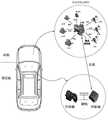
电动汽车中的热管理系统可包括压缩机、水泵、冷凝器、节流装置、换热器、蒸发器以及电池冷却器(Chiller)、水泵、阀门等热管理部件,通过控制器控制各部件的协调工作,保证各种工况下电池和乘员舱均在合适的温度区间范围内。通常情况下,这些零部件分散安装在汽车前舱中的各个位置,由于热管理系统中各个零部件之间均需要采用对应的管路进行连接,因此各个零部件安装位置的分散,会导致热管理系统中的管路错综复杂。此外,每个零部件安装时均需要考虑相应的安装位置和安装空间,给整车的安装布置带来严峻的考验。Thermal management systems in electric vehicles may include compressors, water pumps, condensers, throttling devices, heat exchangers, evaporators, and thermal management components such as battery coolers (Chiller), water pumps, and valves. Coordinate the work to ensure that the battery and crew compartment are within the appropriate temperature range under various operating conditions. Usually, these parts are installed in various positions in the front cabin of the car. Since each part in the thermal management system needs to be connected by corresponding pipelines, the dispersion of the installation position of each part will lead to heat The plumbing in the management system is intricate. In addition, the corresponding installation position and installation space need to be considered when each component is installed, which brings a severe test to the installation layout of the whole vehicle.
本申请实施例对热管理系统进行了重新设计,有利于实现热管理部件的集成。具体可包括两方面的集成:一个是热管理部件的结构上的集成,另一个是热管理部件的电控上的集成。The thermal management system is redesigned in the embodiment of the present application, which is beneficial to realize the integration of thermal management components. Specifically, it may include two aspects of integration: one is the structural integration of the thermal management component, and the other is the electrical control integration of the thermal management component.
首先描述本申请关于结构集成的一些实施方式。First, some embodiments of the present application regarding structural integration are described.
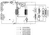
参见图1,图1为本申请实施例提供的一种热管理系统的结构集成示意图。如图1所示,本申请将压缩机、换热器(如后面各个实施例描述的板式换热器)、水泵、水阀等能够主动提供热管理系统所需冷量、热量和水流量的部件,通过结构的紧凑化设计和安装,在结构上集成在热管理集成模块中,而其他具有热管理需求的部件,如汽车中的电机、散热水箱、电池包、空调箱等,则利用水管将其与该热管理集成模块连接起来,通过冷水和热水在连接水管内的流动,实现热管理系统结构集成的功能。Referring to FIG. 1 , FIG. 1 is a schematic structural integration diagram of a thermal management system provided by an embodiment of the present application. As shown in FIG. 1, the present application uses compressors, heat exchangers (such as the plate heat exchangers described in the following embodiments), water pumps, water valves, etc., which can actively provide the cooling capacity, heat and water flow required by the thermal management system. Components, through the compact design and installation of the structure, are structurally integrated in the thermal management integrated module, while other components with thermal management requirements, such as motors in automobiles, cooling water tanks, battery packs, air conditioning boxes, etc., use water pipes It is connected with the thermal management integrated module, and the function of structural integration of thermal management system is realized through the flow of cold water and hot water in the connecting water pipe.
举例来说,参见图2,图2为一种热管理集成模块的示例图,如图2所示,该热管理集成模块可包括压缩机、板式换热器、集成阀、集成阀泵、多功能阀等部件,不同部件之间可通过管道相连。示例性地,多功能阀可以为由水泵、膨胀水壶和水路三通阀形成的集成体;集成阀可以为由水路三通阀和三通水管形成的集成体;集成阀泵可以为由水泵和水路三通阀形成的集成体。上述这些部件可通过一个固定框架布置在一起,从而在整体上又形成一种集成体结构。该集成体结构一方面可方便于通过模块化方式安装在汽车前舱,另一方面通过集成化设计有利于节约占用空间。For example, referring to FIG. 2, FIG. 2 is an example diagram of an integrated thermal management module. As shown in FIG. 2, the integrated thermal management module may include a compressor, a plate heat exchanger, an integrated valve, an integrated valve pump, multiple Components such as functional valves can be connected by pipelines between different components. Exemplarily, the multi-function valve can be an integrated body formed by a water pump, an expansion kettle and a water three-way valve; the integrated valve can be an integrated body formed by a water three-way valve and a three-way water pipe; the integrated valve pump can be an integrated body formed by a water pump and a three-way water pipe. The integrated body formed by the three-way valve of the waterway. The above-mentioned components can be arranged together through a fixed frame, thereby forming an integrated structure as a whole. On the one hand, the integrated body structure can be conveniently installed in the front cabin of the automobile in a modular manner, and on the other hand, it is beneficial to save the occupied space through the integrated design.
需要说明的是,上述图2仅用于示例性解释本申请的一种集成方案,而非限定。集成体结构中各个部件的形状、安装位置、连接关系等均为示例而非限定。It should be noted that the above-mentioned FIG. 2 is only used to exemplarily explain an integration solution of the present application, but is not a limitation. The shape, installation position, connection relationship, etc. of each component in the integrated structure are examples and not limitations.
还需要说明单是,该热管理集成模块中的各个部件还可以不采用固定框架,而是通过其他方式实现集成,例如不同部件之间可以通过管道相连,且在距离上紧凑靠近,而实现集成;又例如不同部件还可进行一体化设计而实现集成,等等。It should also be noted that the components in the thermal management integrated module may not use a fixed frame, but can be integrated in other ways. For example, different components can be connected by pipes, and the distance is compact and close to achieve integration. ; Another example is that different components can also be integrated through integrated design, and so on.
在实际应用中,基于本申请的技术思想还可以设计出其他的集成方案,In practical applications, other integration schemes can also be designed based on the technical ideas of the present application,
例如,可将能够主动提供热管理系统所需冷量、热量和水流量的若干数量的部件,例如压缩机、节流装置、换热器、气液分离器、电磁阀、水泵、阀门等热管理部件中的一个或多个进行集成。For example, a number of components, such as compressors, throttling devices, heat exchangers, gas-liquid separators, solenoid valves, water pumps, valves, etc. One or more of the management components are integrated.
对于若干数量的部件的集成,可以是采用固定框架来固定部件的方式实现集成,还可以是其他方式,例如可以通过固定管道相连而实现集成,又例如还可进行一体化设计而实现集成。For the integration of a number of components, the integration can be achieved by using a fixed frame to fix the components, or other methods, such as connecting through fixed pipes to achieve integration, and for example, integrated design can be used to achieve integration.
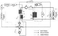
又举例来说,参见图3A,图3A为本申请实施例提供的一种集成阀泵的示例图,如图所示,可将水泵和水路三通阀通过固定框架来固定设置在一起,水泵的输出端通过软的管道或硬的管道连接三通阀的一个输入端即可。For another example, referring to FIG. 3A, FIG. 3A is an example diagram of an integrated valve pump provided by an embodiment of the application. As shown in the figure, the water pump and the water three-way valve can be fixedly arranged together through a fixed frame, and the water pump The output end of the three-way valve can be connected to one input end of the three-way valve through a soft pipe or a hard pipe.
又举例来说,参见图3B,图3B为本申请实施例提供的一种集成阀泵的示例图,如图所示,可通过一体化设计,将水泵和水路三通阀固定设置在一起,即水泵的输出端直接接入到三通阀的一个输入端。For another example, referring to FIG. 3B, FIG. 3B is an example diagram of an integrated valve pump provided by an embodiment of the present application. As shown in the figure, the water pump and the water three-way valve can be fixedly arranged together through an integrated design, That is, the output end of the pump is directly connected to an input end of the three-way valve.
又举例来说,参见图3C,图3C为本申请实施例提供的又一种集成阀泵的示例图,如图所示,可将水泵和水路三通阀通过固定管道来设置在一起,即水泵的输出端连接固定管道的一端,固定管道的另一端连接三通阀的一个输入端。For another example, referring to FIG. 3C, FIG. 3C is an example diagram of another integrated valve pump provided by the embodiment of the present application. As shown in the figure, the water pump and the water three-way valve can be set together through a fixed pipeline, that is, The output end of the water pump is connected to one end of the fixed pipeline, and the other end of the fixed pipeline is connected to an input end of the three-way valve.
需要说明的是,对于若干数量的部件的集成还可以是其他的方式,上述图3A、图3B、图3C实施例仅用于解释申请的方案而非限定。It should be noted that the integration of a certain number of components may also be in other ways, and the above-mentioned embodiments of FIGS. 3A , 3B and 3C are only used to explain the solution of the application, but not limited.
在现有技术中,汽车(例如,电动汽车)热管理系统的零部件分散安装在前舱和乘员舱中,各零部件之间的位置较为发散,对每个零部件进行布置和装配时,均需要考虑相应的安装空间和支架设计等,从而会导致整车的装配布置存在一定的困难。此外,由于热管理系统中零部件分散,导致制冷剂系统的管路较长,制冷剂流动时的沿程阻力增大,制冷剂流量会因为阻力的增大而降低,从而引起系统能效的降低。In the prior art, the components of the thermal management system of an automobile (for example, an electric vehicle) are dispersedly installed in the front cabin and the passenger compartment, and the positions between the components are relatively divergent. When arranging and assembling each component, All need to consider the corresponding installation space and bracket design, which will lead to certain difficulties in the assembly and layout of the vehicle. In addition, due to the dispersion of components in the thermal management system, the pipeline of the refrigerant system is long, and the resistance along the refrigerant flow increases, and the refrigerant flow decreases due to the increase in resistance, which leads to a decrease in the energy efficiency of the system. .
而本申请中,通过对热管理部件的安装位置进行结构集成,能够极大地降低电动汽车的热管理系统的安装体积,节约占用空间;同时,保证各种工况下电池和乘员舱等均在合适的温度区间范围内运行,降低制冷系统中的流动阻力,提高系统能效。In the present application, by structurally integrating the installation positions of the thermal management components, the installation volume of the thermal management system of the electric vehicle can be greatly reduced and the occupied space can be saved; It operates within a suitable temperature range, reduces the flow resistance in the refrigeration system, and improves the energy efficiency of the system.
下面描述本申请关于电控集成的一些实施方式。Some embodiments of the present application regarding electronic control integration are described below.
参见图4,图4展示了本申请实施例的热管理系统的一种电控集成示意图。热管理系统包括用于进行热管理控制的控制器(或称热管理控制器),控制器用于控制压缩机、换热器、水泵、水阀等能够主动提供热管理系统所需冷量、热量和水流量的部件(这样的部件又可称为被控部件)进行工作,从而实现为其他具有热管理需求的部件,如汽车中的电机、散热水箱、电池包、空调箱等提供相关服务。在一种可能的实现中,为了节约乘员舱空间,可将控制器部署于乘员舱的空调箱附近。Referring to FIG. 4, FIG. 4 shows a schematic diagram of an integrated electrical control of the thermal management system according to the embodiment of the present application. The thermal management system includes a controller (or thermal management controller) for thermal management control. The controller is used to control compressors, heat exchangers, water pumps, water valves, etc., and can actively provide the cooling and heat required by the thermal management system. It works with the components of water flow (such components can also be called controlled components), so as to provide related services for other components with thermal management requirements, such as motors, cooling water tanks, battery packs, and air conditioning boxes in automobiles. In a possible implementation, in order to save space in the passenger compartment, the controller may be deployed near the air conditioning box of the passenger compartment.
本申请的一种方案中,可将水泵、阀件、压缩机、节流装置等被控部件的驱动单元(或称驱动电路,或称驱动元件,或称驱动模块,或称驱动单板)与执行机构分离,再将这些被控部件的驱动单元共同集成在一块驱动板(或称集成驱动板,或称集成电路板)上,从而实现各个被控部件的电控集成。在一种可能实现中,该驱动板可以安装在前舱中的压缩机内,也可以单独安装在其他地方。这样,控制器只需要与前舱中的驱动板通过一根总线连接,各个被控部件的执行机构则分别与该驱动板进行电连接。也就是说,控制器可以向驱动板统一发送控制指令,从而通过该驱动板进一步驱动相关部件进行工作,从而实现热管理系统的功能。In one solution of the present application, the drive units (or drive circuits, or drive elements, or drive modules, or drive boards) of controlled components such as water pumps, valves, compressors, and throttling devices can be Separate from the actuator, and then integrate the drive units of these controlled components on a drive board (or integrated drive board, or integrated circuit board), so as to realize the electrical control integration of each controlled component. In one possible implementation, the drive plate can be installed in the compressor in the front compartment, or it can be installed elsewhere separately. In this way, the controller only needs to be connected with the drive board in the front cabin through a bus, and the actuators of each controlled component are electrically connected to the drive board respectively. That is to say, the controller can uniformly send control instructions to the driver board, so that the related components are further driven to work through the driver board, so as to realize the function of the thermal management system.
在现有技术中,汽车(例如,电动汽车)热管理系统的各零部件的电控元件相对独立,每个部件电控元件和热管理控制器之间均需要采用线束进行电连接,这些零部件中的一些分布在前舱,主要有水泵、压缩机、阀件和一些温度传感器,另外一些分布在乘员舱,主要是空调箱中的执行机构和舱内传感器等,而热管理控制器即为传统的空调控制器位于乘员舱,所有存在着这些被控部件均连接至热管理控制器,从而导致电控系统的线束过长。In the prior art, the electronic control elements of each component of the thermal management system of an automobile (eg, electric vehicle) are relatively independent, and a wire harness is required for electrical connection between the electronic control element of each component and the thermal management controller. Some of the components are distributed in the front cabin, mainly including water pumps, compressors, valves and some temperature sensors, while others are distributed in the passenger cabin, mainly the actuators in the air conditioning box and the sensors in the cabin, and the thermal management controller is Because the traditional air conditioning controller is located in the passenger compartment, all of these controlled components are connected to the thermal management controller, resulting in an excessively long wiring harness for the electronic control system.
而本申请中,通过对零部件的驱动单元进行电控集成,使得每个零部件的驱动单板无需与热管理控制器实行单独的线束连接,减少了总线束长度;同时,基于前舱中的热管理部件结构集成,使得零部件与合一的驱动板之间的连接线束也大大缩短。所以实施本申请能够有效减少了热管理系统的线束长度,既节约布线空间,又可以降低布线成本。However, in this application, by electronically integrating the drive units of the components, the drive board of each component does not need to be connected to the thermal management controller by a separate wiring harness, which reduces the length of the bus harness; at the same time, based on the The integrated structure of the thermal management components greatly shortens the wiring harness between the components and the integrated drive board. Therefore, implementing the present application can effectively reduce the length of the wire harness of the thermal management system, which not only saves the wiring space, but also reduces the wiring cost.
下面描述本申请实施例提供的一些热管理系统的结构连接方案,以及基于结构的功能实现方案。下面的各实施例中的附图中,为了方便描述,仅展示一些热管理部件和热需求部件的连接关系以及在功能实现中的工质流向(如制冷剂流向、冷却液流向等),而不展示一些部件中具体的结构集成,以及不展示电控集成中控制器、驱动板、电连接线束等,而基于上文的描述,技术人员将熟悉在具有结构集成和/或电控集成情况下的具体实现方案,本文对这些具体实现方案不展开详述。The following describes the structural connection solutions of some thermal management systems provided by the embodiments of the present application, and the structure-based function implementation solutions. In the drawings in the following embodiments, for the convenience of description, only the connection relationship between some heat management components and heat demand components and the working medium flow direction (such as refrigerant flow direction, cooling liquid flow direction, etc.) in the function realization are shown, while The specific structural integration in some components is not shown, and the controller, driver board, electrical connection harness, etc. in the electronic control integration are not shown, but based on the above description, the skilled person will be familiar with the situation with structural integration and/or electronic control integration. The specific implementation schemes below are not described in detail in this article.
参见图5,图5是本申请实施例提供的一种热管理系统的结构示意图,如图4所示,该热管理系统包括:制冷剂环路系统、电机液冷环路系统、空调液冷环路系统,其中:Referring to FIG. 5, FIG. 5 is a schematic structural diagram of a thermal management system provided by an embodiment of the present application. As shown in FIG. 4, the thermal management system includes: a refrigerant loop system, a motor liquid cooling loop system, and an air conditioner liquid cooling system. Loop system, where:
制冷剂环路系统包括:压缩机1、制冷剂四通换向阀2、第一板式换热器3、节流阀4、第二板式换热器5和气液分离器6。第一板式换热器3和第二板式换热器5均含有两对进出口通道,其中一对进出口通道为制冷剂通道,用于流通制冷剂,另一对进出口通道为液冷通道,用于流通冷却液。制冷剂通道的制冷剂和液冷通道的冷却液之间可进行热量交换(简称热交换,或称换热)。The refrigerant loop system includes: a compressor 1 , a refrigerant four-
压缩机1的出口通过管道与制冷剂四通换向阀2的第一端(即A端)连接,四通换向阀2的第二端(即B端)与第一板式换热器3中的制冷剂通道的第一端连接,第一板式换热器3中的制冷剂通道的第二端与节流阀4的第一端连接,所述节流阀4的第二端与所述第二板式换热器5中的制冷剂通道的第一端连接,所述第二板式换热器5中的制冷剂通道的第二端与制冷剂四通换向阀2的第三端(即C端)连接,制冷剂四通换向阀2的第四端(即D端)与气液分离器6的第一端连接,气液分离器6的第二端与压缩机1的入口连接,以形成制冷剂环路,制冷剂环路为用于循环流通制冷剂。The outlet of the compressor 1 is connected to the first end (ie the A end) of the refrigerant four-
电机液冷环路系统包括经由电机的循环流通冷却液的电机液冷环路,且电机液冷环路中的两段管道分别接入第一板式换热器3中的液冷通道的第一端和第二端;电机液冷环路系统的与制冷剂环路系统通过第一板式换热器3进行换热,即电机液冷环路系统的冷却液与制冷剂环路系统的制冷剂可在第一板式换热器3中进行热交换。The motor liquid cooling loop system includes a motor liquid cooling loop through which the cooling liquid circulates through the motor, and the two sections of pipes in the motor liquid cooling loop are respectively connected to the first part of the liquid cooling channel in the first
空调液冷环路系统包括经由空调箱的循环流通冷却液的空调液冷环路,且空调液冷环路中的管道分别接入第二板式换热器5中的液冷通道的第一端和第二端;空调液冷环路系统与制冷剂环路系统通过第二板式换热器5进行换热,即空调液冷环路系统的冷却液与制冷剂环路系统的制冷剂可在第二板式换热器5中进行热交换。The air-conditioning liquid-cooling loop system includes an air-conditioning liquid-cooling loop through which the cooling liquid circulates through the air-conditioning box, and the pipes in the air-conditioning liquid-cooling loop are respectively connected to the first ends of the liquid-cooling passages in the second
在一种具体实施方案中,制冷剂四通阀的A-B端、C-D端联通,压缩机1排出的高温制冷剂经过制冷剂四通阀2的A-B端进入第一板式换热器3进行冷凝放热,通过节流阀4以后节流成低温气液两相制冷剂,然后经过第二板式换热器5进行蒸发吸热,从第二板式换热器5中吸收乘员舱(空调机安装在乘员舱)中的热量,最后经过制冷剂四通阀2的D-C端进入气液分离器6,由气液分离器6的出口进入到压缩机1的吸气口,从而实现制冷剂的循环。电机液冷环路系统的冷却液可通过第一板式换热器3吸收热量,并通过电机液冷环路实现散热。In a specific embodiment, the A-B and C-D ends of the refrigerant four-way valve are connected, and the high-temperature refrigerant discharged from the compressor 1 enters the first
在又一种具体实施方案中,制冷剂四通阀的A-D端、B-C端联通,压缩机1排出的高温制冷剂经过制冷剂四通阀2的A-D端进入第二板式换热器5进行冷凝放热,提供乘员舱(空调机安装在乘员舱)加热所需的热量,通过节流阀4以后节流成低温气液两相制冷剂,然后经过第一板式换热器3进行蒸发吸热,最后经过制冷剂四通阀2的B-C端进入气液分离器6,由气液分离器6的出口进入到压缩机1的吸气口。电机液冷环路系统的冷却液可吸收电机液冷环路中的热量(例如电机热量),并通过第一板式换热器3释放热量,从而实现热量回收,提高制冷剂环路系统的工作效率。In another specific embodiment, the A-D ends and B-C ends of the refrigerant four-way valve are connected, and the high-temperature refrigerant discharged from the compressor 1 enters the second
本申请实施例的热管理系统可应用于传统能源汽车(内燃机汽车),也可能被应用于新能源汽车(例如电动汽车、混动汽车等)。The thermal management system of the embodiments of the present application can be applied to traditional energy vehicles (internal combustion engine vehicles), and may also be applied to new energy vehicles (eg, electric vehicles, hybrid vehicles, etc.).
可以看到,本申请实施例中,通过使用制冷剂四通换向阀,简化了制冷剂环路系统的环路;通过使用两个板式换热器,使得制冷剂环路的制冷剂可以通过第一板式换热器3与电机液冷环路的冷却液进行热交换,以及通过第二板式换热器5与空调液冷环路的冷却液进行热交换,从而避免了平行流换热器的使用。由于板式换热器体积相对较小,通过板式换热器和冷却液换热方法的应用,使热管理系统的结构化集成的方案可以被实现,也使得热管理系统的电控集成的方案可以被实现。所以,实施本申请实施例,有利于实现节约热管理系统在前舱的占用空间,也有利于节约热管理系统的成本。It can be seen that in the embodiment of the present application, by using the refrigerant four-way reversing valve, the loop of the refrigerant loop system is simplified; by using two plate heat exchangers, the refrigerant in the refrigerant loop can pass through The first
参见图6,图6是本申请实施例提供的又一种热管理系统的结构示意图,如图6所示,该热管理系统与图5所示热管理系统的区别在于,图6的热管理系统在图5所示热管理系统的基础上增加了电池液冷环路系统,电池液冷环路系统包括经由电池包的循环流通冷却液的电池液冷环路,且电池液冷环路和前述空调液冷环路系统共用管道接入第二板式换热器5中的液冷通道的第一端和第二端;电池液冷环路系统与制冷剂环路系统通过所述第二板式换热器5进行换热,即电池液冷环路系统的冷却液也可以和制冷剂环路系统的制冷剂在第二板式换热器5中进行热交换。Referring to FIG. 6 , FIG. 6 is a schematic structural diagram of another thermal management system provided by an embodiment of the present application. As shown in FIG. 6 , the thermal management system differs from the thermal management system shown in FIG. 5 in that the thermal management system in FIG. 6 The system adds a battery liquid cooling loop system based on the thermal management system shown in Figure 5. The battery liquid cooling loop system includes a battery liquid cooling loop that circulates the cooling liquid through the battery pack, and the battery liquid cooling loop and The aforementioned air-conditioning liquid-cooling loop system shared pipes are connected to the first and second ends of the liquid-cooling channel in the second
在一种具体实施方案中,制冷剂四通阀的A-B端、C-D端联通,压缩机1排出的高温制冷剂经过制冷剂四通阀2的A-B端进入第一板式换热器3进行冷凝放热,通过节流阀4以后节流成低温气液两相制冷剂,然后经过第二板式换热器5进行蒸发吸热,从第二板式换热器5中吸收乘员舱(空调机安装在乘员舱)中的热量,和/或,从第二板式换热器5中吸收电池液冷环路的电池包中的热量。最后经过制冷剂四通阀2的D-C端进入气液分离器6,由气液分离器6的出口进入到压缩机1的吸气口,从而实现制冷剂的循环。电机液冷环路系统的冷却液可通过第一板式换热器3吸收热量,并通过电机液冷环路实现散热。In a specific embodiment, the A-B and C-D ends of the refrigerant four-way valve are connected, and the high-temperature refrigerant discharged from the compressor 1 enters the first
在又一种具体实施方案中,制冷剂四通阀的A-D端、B-C端联通,压缩机1排出的高温制冷剂经过制冷剂四通阀2的A-D端进入第二板式换热器5进行冷凝放热,提供乘员舱(空调机安装在乘员舱)加热所需的热量,和/或,提供电池液冷环路的电池包加热所需的热量。通过节流阀4以后节流成低温气液两相制冷剂,然后经过第一板式换热器3进行蒸发吸热,最后经过制冷剂四通阀2的B-C端进入气液分离器6,由气液分离器6的出口进入到压缩机1的吸气口。电机液冷环路系统的冷却液可吸收电机液冷环路中的热量(例如电机热量),并通过第一板式换热器3释放热量,从而实现热量回收,提高制冷剂环路系统的工作效率。In another specific embodiment, the A-D ends and B-C ends of the refrigerant four-way valve are connected, and the high-temperature refrigerant discharged from the compressor 1 enters the second
本申请实施例的热管理系统可能被应用于新能源汽车(例如电动汽车、混动汽车等)。The thermal management system of the embodiments of the present application may be applied to new energy vehicles (eg, electric vehicles, hybrid vehicles, etc.).
可以看到,本申请实施例中,通过使用制冷剂四通换向阀,简化了制冷剂环路系统的环路;通过使用两个板式换热器,使得制冷剂环路的制冷剂可以通过第一板式换热器3与电机液冷环路的冷却液进行热交换,以及通过第二板式换热器5与空调液冷环路的冷却液进行热交换,和/或,通过第二板式换热器5与电池液冷环路的冷却液进行热交换,从而避免了平行流换热器的使用。由于板式换热器体积相对较小,通过板式换热器和冷却液换热方法的应用,使热管理系统的结构化集成的方案可以被实现,也使得热管理系统的电控集成的方案可以被实现。所以,实施本申请实施例,有利于实现节约热管理系统在前舱的占用空间,也有利于节约热管理系统的成本。It can be seen that in the embodiment of the present application, by using the refrigerant four-way reversing valve, the loop of the refrigerant loop system is simplified; by using two plate heat exchangers, the refrigerant in the refrigerant loop can pass through The first
基于图6实施例所展示的热管理系统,下面示例性描述在一种实现场景中热管理系统中的相关部件的连接关系。具体参见图7,图7是本申请实施例提供的一种热管理系统的详细结构示意图,如图7所示,该热管理系统为包含有制冷剂四通换向阀结构的集成化热管理系统。这里集成的有集成体7、多功能阀8、集成阀14、集成阀泵15和集成壶泵18。Based on the thermal management system shown in the embodiment of FIG. 6 , the following exemplarily describes the connection relationship of related components in the thermal management system in an implementation scenario. Referring specifically to FIG. 7, FIG. 7 is a schematic diagram of a detailed structure of a thermal management system provided by an embodiment of the present application. As shown in FIG. 7, the thermal management system is an integrated thermal management system including a refrigerant four-way reversing valve structure system. Integrated here are an
其中,集成体7具体为由多个板式换热器(第一板式换热器3和第二第二板式换热器5)和制冷剂四通换向阀2以及节流阀4组成的集成体,制冷剂温度压力传感器可以布置在连接各个集成元件的管路上。Wherein, the
多功能阀8为由第二水泵8-1、膨胀水壶8-2和第一水路三通阀8-3组成的集成体,多功能阀8用于实现水泵、水流换向(或称冷却液换向)和蓄水功能。其中,第一水路三通阀8-3的第一端连接膨胀水壶8-2的一端,第一水路三通阀8-3的第二端提供对外接口(图示中记为B端,例如可用于连接电池包16),第一水路三通阀8-3的第三端提供对外接口(图示中记为C端,例如可用于连接第一板式换热器3);膨胀水壶8-2的另一端连接第二水泵8-1的一端,第二水泵8-1的另一端提供对外接口(图示中记为A端,例如可用于连接所述功率器件9)。The
集成阀14为由第二水路三通阀14-1和三通水管组成的集成体,用于实现水流换向功能。其中,第二水路三通阀14-1的第一端提供对外接口(图示中记为A端,例如用于连接所述电机11),第二水路三通阀14-1的第二端提供对外接口(图示中记为B端,例如用于连接散热水箱12),第二水路三通阀14-1的第三端连接三通水管的第一端,三通水管的第二端提供对外接口(图示中记为C端,例如用于连接第一板式换热器3),三通水管的第三端提供对外接口(图示中记为C端,例如用于连接集成阀泵15)。The
集成阀泵15为由第三水泵15-1和第三水路三通阀15-2组成的集成体,用于实现水泵和水流换向功能。其中,第三水泵15-1的一端提供对外接口(图示中记为A端,例如用于连接到第二板式换热器5),第三水泵15-1的另一端连接第三水路三通阀15-2的第一端,第三水路三通阀15-2的第二端可提供两路对外接口,例如图示中可通过三通水管提供对外接口B端和D端,B端例如用于连接集成阀14,D端例如用于连接第二电加热器17;第三水路三通阀15-2的第三端提供对外接口(图示中记为C端,例如用于连接空调换热器21。The
集成壶泵18为由第一水泵18-2和膨胀水壶18-1组成的集成体,用于实现水泵和蓄水功能。膨胀水壶18-1的一端和第一水泵18-2的一端连接,膨胀水壶18-1的另一端提供对外接口(例如用于连接暖风芯体20),第一水泵18-2另一端提供对外接口(例如用于连接第一电加热器19)。The
在图7所示的热管理系统中,制冷剂环路的连接关系如下:压缩机1的出口与制冷剂四通换向阀2的A端连接,制冷剂四通换向阀2的B端与第一板式换热器3的一端(即第一板式换热器3的制冷剂通道的一端)连接,第一板式换热器3的另一端(即第一板式换热器3的制冷剂通道的另一端)与节流阀4的一端连接,节流阀4的另一端连接第二板式换热器5的一端(即第二板式换热器5的制冷剂通道的一端),第二板式换热器5的另一端(即第二板式换热器5的制冷剂通道的另一端)连接制冷剂四通换向阀2的D端,制冷剂四通换向阀的C端与气液分离器6的一端连接,气液分离器6的另一端与压缩机1的入口连接。这里节流阀4可为双向节流的节流阀,节流阀4可以使用毛细管、膨胀阀等具有节流功能的元件来实现。In the thermal management system shown in Figure 7, the connection relationship of the refrigerant loop is as follows: the outlet of the compressor 1 is connected to the A-end of the refrigerant four-
在图7所示的热管理系统中,电池液冷环路的连接关系如下:集成阀泵15的A端与第二板式换热器5的一端(即第二板式换热器5的液冷通道的一端)连接,D端则与第二电加热器17的一端连接,第二电加热器17的另一端则连接电池包15的冷却装置的入口,电池包16的冷却装置的出口则可以通过三通水管,同时连接第二板式换热器5的另一端(即第二板式换热器5的液冷通道的另一端)和多功能阀8的B端。In the thermal management system shown in FIG. 7 , the connection relationship of the battery liquid cooling loop is as follows: the A-end of the
电池包15的冷却装置为通过流通冷却液来实现对电池包进行加热或冷却的装置,例如电池包15的冷却装置可以为与电池包接触的水冷盘管、冷却板等,本文不做限定。The cooling device of the
另外,需要说明的是,本文中,为了叙述的方便,有时也把“连接电池包15的冷却装置”简述为“连接电池包15”,把“电池包15的冷却装置的入口”简述为“电池包15的入口”,把“电池包15的冷却装置的出口”简述为“电池包15的出口”。In addition, it should be noted that, in this article, for the convenience of description, sometimes "connecting the cooling device of the
在图7所示的热管理系统中,空调液冷环路(这里也可称为乘员舱液冷环路)的连接关系如下:集成阀泵15的C端和供热通风与空气调节(Heating,Ventilation and AirConditioning,HVAC)系统内的空调换热器21的一端连接,空调换热器21的另一端则可通过三通水管,与电池包16的出口合并后共同接入第二板式换热器5的另一端。HVAC系统具体可包括空调换热器21、暖风芯体20和风扇22。空调换热器21可用于实现乘员舱制冷功能,暖风芯体20可用于实现乘员舱制热功能,风扇22可用于实现乘员舱的吹风功能。上述器件的组合还可实现其他功能,例如空调换热器21和暖风芯体20共同用于实现乘员舱除湿功能。In the thermal management system shown in FIG. 7 , the connection relationship of the air-conditioning liquid cooling loop (here may also be referred to as the passenger compartment liquid cooling loop) is as follows: the C terminal of the
此外,在可能的实施例中,在图7所示的热管理系统中,还可以包括暖风液冷环路(又可称为乘员舱暖风环路),暖风液冷环路的连接关系如下:集成壶泵18的出口(即第一水泵18-2的出口)连接第一电加热器19,第一电加热器19的另一端连接HVAC内的暖风芯体20,暖风芯体20的另一端则连接集成壶泵18的入口(即膨胀水壶18-1的入口)。In addition, in a possible embodiment, the thermal management system shown in FIG. 7 may further include a warm air liquid-cooling loop (also called a passenger cabin warm air loop), and the connection of the warm air liquid-cooling loop The relationship is as follows: the outlet of the integrated pot pump 18 (ie the outlet of the first water pump 18-2) is connected to the first
在图7所示的热管理系统中,电机液冷环路(又可称为动力系统液冷环路)的连接关系如下:多功能阀8的C端(即第一水路三通阀8-3的C端,或称多功能阀8的第三端)连接第一板式换热器3的一端,多功能阀8的A端(即第二水泵8-1的A端)与功率器件8的冷却装置一端连接,功率器件9的冷却装置的另外一端与电机控制器10的冷却装置一端连接,电机控制器10的冷却装置另外一端与电机11的冷却装置一端连接,电机11的冷却装置的另一端分别与散热水箱12和集成阀14的A端(即第二水路三通阀14-1的A端)连接,散热水箱12的另一端则与集成阀14的B端(即第二水路三通阀14-1的B端)连接。集成阀14的C端(即第二水路三通阀14-1的C端)与第一板式换热器3的另一端连接,集成阀14的D端(即三通水管的一端)可与集成阀泵15的B端连接。In the thermal management system shown in FIG. 7 , the connection relationship of the motor liquid cooling loop (also known as the power system liquid cooling loop) is as follows: the C end of the multi-function valve 8 (ie the first three-way valve 8- The C end of 3, or the third end of the multifunctional valve 8) is connected to one end of the first
需要说明的是,功率器件9的冷却装置为通过流通冷却液来实现对功率器件进行加热或冷却的装置,电机控制器10的冷却装置为通过流通冷却液来实现对电机控制器进行加热或冷却的装置,电机11的冷却装置为通过流通冷却液来实现对电机进行加热或冷却的装置。It should be noted that the cooling device of the
本文中,为了叙述的方便,有时也把“连接功率器件9的冷却装置”简述为“连接功率器件9”,把“连接电机控制器10的冷却装置”简述为“连接电机控制器10”,把“连接电机11的冷却装置”简述为“连接电机11”。In this paper, for the convenience of description, sometimes "the cooling device connected to the
需要说明的是,集成体7、多功能阀8、集成阀14、集成阀泵15和集成壶泵18各自的具体集成方式还可类似参考前文图3A、图3B、图3C实施例的相关描述,为了说明书的简洁,这里不再赘述。It should be noted that, the specific integration methods of the
除此之外,集成体7、多功能阀8、集成阀14、集成阀泵15和集成壶泵18还可以共同集成在一起,成为前文所述的热管理集成模块。In addition, the
基于图7实施例的结构连接关系,下面将对主要的应用场景进行示例性地阐述。Based on the structural connection relationship of the embodiment in FIG. 7 , the following will exemplarily describe the main application scenarios.
参见图8,图8为在实现乘员舱冷却、电池冷却以及电机冷却场景下,热管理系统中相关的工质流向示意图,具体包括制冷剂环路流向示意、电机液冷环路流向示意、空调液冷环路流向示意和电池液冷环路流向示意。本文中,热管理系统中的灰色区域均表示无需工质通过的环路。Referring to FIG. 8, FIG. 8 is a schematic diagram of the related working medium flow in the thermal management system under the scenarios of achieving passenger compartment cooling, battery cooling and motor cooling, including the flow direction of the refrigerant loop, the flow direction of the motor liquid cooling loop, and the flow direction of the air conditioner. The flow direction of the liquid cooling loop and the flow direction of the battery liquid cooling loop are shown. In this paper, the gray areas in the thermal management system all represent loops that do not require working fluids to pass through.
如图8所示,制冷剂环路流向描述如下:制冷剂四通阀2的A-B端、D-C端联通,压缩机1排出的高温制冷剂经过制冷剂四通阀2的A-B端进入第一板式换热器3进行冷凝放热,通过节流阀4以后节流成低温气液两相制冷剂,然后经过第二板式换热器5进行蒸发吸热,从第二板式换热器5中吸收电池和乘员舱中的热量,最后经过制冷剂四通阀2的D-C端进入气液分离器6,由气液分离器6的出口进入到压缩机1的吸气口。As shown in Figure 8, the flow direction of the refrigerant loop is described as follows: the A-B and D-C ends of the refrigerant four-
电机液冷环路流向描述如下:电机液冷环路的多功能阀8的B端关闭,C端接受从第一板式换热器3中输出的高温液体,经由A端输出后,依次经过功率器件9、电机控制器10和电机11,通过关闭集成阀14的A端,使得高温液体经由散热水箱12冷却,可选的还可以利用风扇13进一步散热,然后再次进入到第一板式换热器3中。The flow direction of the motor liquid cooling loop is described as follows: the B end of the
空调液冷环路流向和电池液冷环路流向分别描述如下:同属于电池液冷环路和空调液冷环路的集成阀泵15的C端和D端打开,A端接收从第二板式换热器5中输出的低温液体,低温液体一部分从C端输出,经过空调换热器21,达到冷却乘员舱的目的。低温液体另一部分从D端输出,经过第二电加热器17,吸收电池包16中电池的热量,达到冷却电池包16的目的。此时第二电加热器17没有打开,仅作为流通功能。吸收了电池和乘员舱的热量后的液体经过三通水管,再次进入到第二板式换热器5中。可选的,可以通过调节集成阀泵15中的水路三通阀的开度,实现调节电池包和乘员舱冷量分配的功能。The flow directions of the air-conditioning liquid cooling loop and the battery liquid cooling loop are respectively described as follows: the C and D ends of the
参见图9,图9为在实现乘员舱制热和电池制热场景下,热管理系统中相关的工质流向示意图,具体包括制冷剂环路流向示意、电机液冷环路流向示意、空调液冷环路流向示意、电池液冷环路流向示意和暖风液冷环路流向示意。Referring to FIG. 9, FIG. 9 is a schematic diagram of the relevant working medium flow in the thermal management system under the scenario of realizing the heating of the passenger compartment and the battery, including the flow direction of the refrigerant loop, the flow direction of the motor liquid cooling loop, the flow direction of the air-conditioning liquid The flow direction of the cold loop, the flow direction of the battery liquid cooling loop, and the flow direction of the warm air liquid cooling loop are shown.
如图9所示,制冷剂环路流向描述如下:制冷剂四通阀2的A-D端、B-C端联通,压缩机1排出的高温制冷剂经过制冷剂四通阀2的A-D端进入第二板式换热器5进行冷凝放热,提供为电池和乘员舱加热所需要的热量;通过节流阀4以后节流成低温气液两相制冷剂,然后经过第一板式换热器3进行蒸发吸热,从第一板式换热器3中电机中的余热或者环境中的热量,最后经过制冷剂四通阀2的B-C端进入气液分离器6,由气液分离器6的出口进入到压缩机1的吸气口。As shown in Figure 9, the flow direction of the refrigerant loop is described as follows: the A-D and B-C ends of the refrigerant four-
电机液冷环路流向描述如下:电机液冷环路的多功能阀8的B端关闭,C端接受从第一板式换热器3中输出的低温液体,经由A端输出后,依次经过功率器件9、电机控制器10和电机11。在电机开启的情况下,可以关闭集成阀14的B端,使得电机11出来的高温液体直接从集成阀14的A端进入、C端输出到第一板式换热器3中,提供蒸发所需的热量。而当电机关闭的情况下,则将集成阀14的A端关闭,B端开启,使得低温液体从电机11出来后,从环境中吸收热量,再从集成阀的C端进入到第一板式换热器3中。The flow direction of the motor liquid cooling loop is described as follows: the B end of the
空调液冷环路流向和电池液冷环路流向分别描述如下:同属于电池液冷环路和空调液冷环路的集成阀泵15的C端和D端打开,A端接收从第二板式换热器5中输出的高温液体,分别从C端输出,经过空调换热器21,达到加热乘员舱的目的;从D端输出,经过第二电加热器17,达到加热电池包16的目的,加热电池和乘员舱后的低温液体经由三通水管,再次进入到第二板式换热器5中。可选的,通过调节集成阀泵15中水路三通阀的开度,实现调节电池和乘员舱热量分配的功能。The flow directions of the air-conditioning liquid cooling loop and the battery liquid cooling loop are respectively described as follows: the C and D ends of the
暖风液冷环路流向描述如下:若集成阀泵15的C、D端出口水温不够,可以将第二电加热器17打开,实现辅助加热电池的功能,将集成壶泵18和第一电加热器19打开,实现辅助加热乘员舱的功能。The flow direction of the warm air liquid cooling loop is described as follows: if the water temperature at the C and D ends of the
参见图10,图10为在实现电池自然冷却场景下,热管理系统中相关的工质流向示意图,如图10所示,在环境温度较低,只有电池和电机自然冷却的需求时。制冷剂回路关闭,电池和电机的热量可通过散热水箱12来实现自然冷却。Referring to Figure 10, Figure 10 is a schematic diagram of the relevant working fluid flow in the thermal management system under the scenario of realizing the natural cooling of the battery. As shown in Figure 10, when the ambient temperature is low, only the natural cooling of the battery and the motor is required. The refrigerant circuit is closed, and the heat of the battery and the motor can pass through the cooling
具体的,液冷环路的走向描述如下:多功能阀8的C端关闭,B端接受电池包16出口的高温液体,A端排出的高温液体分别经过功率器件9、电机控制器10和电机11。此时集成阀14的A端关闭,使得电机11出口的高温液体经过散热水箱12冷却为低温液体,由于多功能阀8的C端关闭,因此散热水箱12出来的低温液体只能通过集成阀14的D端进入到集成阀泵15的B端。该情形下,关闭集成阀泵15内三通水阀与B和D端连接的口,使低温液体由集成阀泵15的D端排出,流经未开启的第二电加热器17,进入到电池包16,实现冷却电池的目的。Specifically, the direction of the liquid cooling loop is described as follows: the C end of the
参见图11,图11为在实现电池加热和乘员舱除湿场景下,热管理系统中相关的工质流向示意图,具体包括制冷剂环路流向示意、电机液冷环路流向示意、空调液冷环路流向示意、电池液冷环路流向示意和暖风液冷环路流向示意。Referring to Fig. 11, Fig. 11 is a schematic diagram of the flow direction of the relevant working medium in the thermal management system under the scenario of realizing battery heating and dehumidification of the passenger compartment, including the flow direction of the refrigerant loop, the flow direction of the motor liquid cooling loop, and the air conditioning liquid cooling loop. Circuit flow diagram, battery liquid cooling circuit flow diagram and warm air liquid cooling circuit flow diagram.
如图11所示,制冷剂环路流向描述如下:制冷剂四通阀2的A-B端、D-C端联通,压缩机1排出的高温制冷剂经过制冷剂四通阀2的A-B端进入第一板式换热器3进行冷凝放热,通过节流阀4以后节流成低温气液两相制冷剂,然后经过第二板式换热器5进行蒸发吸热,从第二板式换热器5中吸收乘员舱中的热量,最后经过制冷剂四通阀2的D-C端进入气液分离器6,由气液分离器6的出口进入到压缩机1的吸气口。As shown in Figure 11, the flow direction of the refrigerant loop is described as follows: the A-B and D-C ends of the refrigerant four-
电机液冷环路流向描述如下:电机液冷环路的多功能阀8的B端和C端同时开启,C端接受从第一板式换热器3中输出的高温液体,B端接收从电池包16输出的低温液体,经由A端输出后,依次经过功率器件9、电机控制器10和电机11。此情景下,关闭集成阀14的B端,使得电机11出来的高温液体从集成阀14的A端进入,再分别由集成阀14的C端输出至第一板式换热器3中,由集成阀14的D端,经由集成阀泵15的B端和D端,流经第二电加热器17后进入到电池包16中。The flow direction of the motor liquid cooling loop is described as follows: the B and C terminals of the
空调液冷环路流向描述如下:空调液冷环路的集成阀泵15的A端接收第二板式换热器5输出的低温液体,经由C端输出后进入到HVAC内的空调换热器21,空调换热器21出口的高温液体再返回至第二板式换热器5中。The flow direction of the air-conditioning liquid-cooling loop is described as follows: the A-end of the
暖风液冷环路流向描述如下:暖风液冷环路的集成壶泵18和第一电加热器19打开,使得空调换热器21制冷、暖风芯体20制热、从而实现乘员舱除湿的功能。The flow direction of the warm air liquid cooling loop is described as follows: the
电池液冷环路流向描述如下:多功能阀8的B端接受电池包16出口的低温液体,A端排出的低温液体分别经过功率器件9、电机控制器10和电机11。此时集成阀14的B端关闭,使得电机11出口的高温液体经过通过集成阀14的B端进入,再从集成阀14的D端进入到集成阀泵15的B端,D端流出到第二电加热器17,进入到电池包16,实现加热电池的目的。The flow direction of the battery liquid cooling loop is described as follows: the B terminal of the
参见图12,图12为在实现电池自然冷却和乘员舱加热场景下,热管理系统中相关的工质流向示意图,具体包括制冷剂环路流向示意、电机液冷环路流向示意、空调液冷环路流向示意、电池液冷环路流向示意和暖风液冷环路流向示意。Referring to Fig. 12, Fig. 12 is a schematic diagram of the relevant working medium flow in the thermal management system under the scenario of realizing natural cooling of the battery and heating of the passenger compartment, including the flow direction of the refrigerant loop, the flow direction of the motor liquid cooling loop, and the liquid cooling of the air conditioner. The flow direction of the loop, the flow direction of the battery liquid cooling loop and the flow direction of the warm air liquid cooling loop are shown.
如图12所示,制冷剂环路流向描述如下:制冷剂四通阀2的A-D端、B-C端联通,压缩机1排出的高温制冷剂经过制冷剂四通阀2的A-D端进入第二板式换热器5进行冷凝放热,提供乘员舱加热所需的热量,通过节流阀4以后节流成低温气液两相制冷剂,然后经过第一板式换热器3进行蒸发吸热,最后经过制冷剂四通阀2的B-C端进入气液分离器6,由气液分离器6的出口进入到压缩机1的吸气口。As shown in Figure 12, the flow direction of the refrigerant loop is described as follows: the A-D and B-C ends of the refrigerant four-
电机液冷环路流向描述如下:电机液冷环路的多功能阀8的B端和C端同时开启,C端接受从第一板式换热器3中输出的低温液体,B端接收从电池包16输出的高温液体,经由A端输出后,依次经过功率器件9、电机控制器10和电机11。此情景下,关闭集成阀14的A端,使得电机11出来的高温液体经由散热水箱12后冷却成低温液体,从集成阀14的B端进入,然后分别由集成阀14的C端输出至第一板式换热器3中,由集成阀14的D端,经由集成阀泵15的B端和D端,流经第二电加热器17后进入到电池包16中。The flow direction of the motor liquid cooling loop is described as follows: the B and C terminals of the
空调液冷环路流向描述如下:乘员舱液冷环路的集成阀泵15的A端接收第二板式换热器5输出的高温液体,经由C端输出后进入到HVAC内的空调换热器21,空调换热器21出口的低温液体再返回至第二板式换热器5中。The flow direction of the air-conditioning liquid-cooling loop is described as follows: the A-end of the
暖风液冷环路流向描述如下:若集成阀泵15的C端输出的热量不够,可将乘员舱暖风环路的集成壶泵18和第一电加热器19打开,实现辅助加热乘员舱的功能。The flow direction of the warm air liquid cooling loop is described as follows: if the output heat from the C end of the
电池液冷环路流向描述如下:多功能阀8的B端接受电池包16出口的高温液体,A端排出的高温液体分别经过功率器件9、电机控制器10和电机11。此时集成阀14的A端关闭,使得电机11出口的高温液体经过散热水箱12冷却为低温液体,经过通过集成阀14的B端进入,再从集成阀14的D端进入到集成阀泵15的B端,D端流出并流经未开启的第二电加热器17,进入到电池包16,实现自然冷却电池的目的。The flow direction of the battery liquid cooling loop is described as follows: the B end of the
可以看到,本申请实施例中,通过使用制冷剂四通换向阀,简化了制冷剂环路系统的环路;通过使用两个板式换热器,使得制冷剂环路的制冷剂可以通过第一板式换热器3与电机液冷环路的冷却液进行热交换,以及通过第二板式换热器5与空调液冷环路的冷却液进行热交换,和/或,通过第二板式换热器5与电池液冷环路的冷却液进行热交换,从而避免了平行流换热器的使用。由于板式换热器体积相对较小,通过板式换热器和冷却液换热方法的应用,使热管理系统的结构化集成的方案可以被实现,可以使系统中主要零部件集成在不同的集成体中;也使得热管理系统的电控集成的方案可以被实现,解决了制冷剂管路和电控线束过长的问题。并且,本申请实施例同样可以适用于各种各样的实际应用场景,例如乘员舱制冷/加热/除湿,电池制冷/加热,电机冷却/热量回收等。所以,实施本申请实施例,有利于实现节约热管理系统在前舱的占用空间,也有利于节约热管理系统的成本。It can be seen that in the embodiment of the present application, by using the refrigerant four-way reversing valve, the loop of the refrigerant loop system is simplified; by using two plate heat exchangers, the refrigerant in the refrigerant loop can pass through The first
参见图13,图13是本申请实施例提供的又一种热管理系统的结构示意图,如图13所示,该热管理系统包括:制冷剂环路系统、电机液冷环路系统、暖风液冷环路系统,其中:Referring to FIG. 13, FIG. 13 is a schematic structural diagram of another thermal management system provided by an embodiment of the present application. As shown in FIG. 13, the thermal management system includes: a refrigerant loop system, a motor liquid cooling loop system, a warm air Liquid cooling loop system where:
制冷剂环路系统包括:压缩机101、第一板式换热器102、第一节流阀103、第二板式换热器104、第二节流阀109、蒸发器110(或称空调蒸发器110)和气液分离器107。第一板式换热器102和第二板式换热器104均含有两对进出口通道,其中一对进出口通道为制冷剂通道,用于流通制冷剂,另一对进出口通道为液冷通道,用于流通冷却液。制冷剂通道的制冷剂和液冷通道的冷却液之间可进行热量交换(简称热交换,或称换热)。The refrigerant loop system includes: a
压缩机101、第一板式换热器102、第一节流阀103、第二板式换热器、第二节流阀109、空调蒸发器110和气液分离器107依次串联接通形成环路,具体的,压缩机101的出口通过管道与第一板式换热器102中的制冷剂通道的第一端连接,第一板式换热器102中的制冷剂通道的第二端与第一节流阀103的第一端连接,第一节流阀103的第二端与第二板式换热器中的制冷剂通道的第一端连接,第二板式换热器中的制冷剂通道的第二端与第二节流阀109的第一端连接,第二节流阀109的第二端与空调蒸发器110的第一端连接,空调蒸发器110的第二端与气液分离器107的第一端连接,气液分离器107的第二端接入到压缩机101的入口。从而,以形成制冷剂环路(或称第一制冷剂环路),制冷剂环路为用于循环流通制冷剂。The
电机液冷环路系统包括经由电机的循环流通冷却液的电机液冷环路,且电机液冷环路中的两段管道分别接入板式换热器103中的液冷通道的第一端和第二端;电机液冷环路系统的与制冷剂环路系统通过板式换热器103进行换热,即电机液冷环路系统的冷却液与制冷剂环路系统的制冷剂可在板式换热器103中进行热交换。The motor liquid cooling loop system includes a motor liquid cooling loop through which the cooling liquid circulates through the motor, and the two sections of pipes in the motor liquid cooling loop are respectively connected to the first end and the first end of the liquid cooling channel in the
暖风液冷环路系统包括经由暖风芯体的循环流通冷却液的暖风液冷环路,且暖风液冷环路中的管道分别接入第一板式换热器102中的液冷通道的第一端和第二端;暖风液冷环路系统与制冷剂环路系统通过第一板式换热器102进行换热,即空调液冷环路系统的冷却液与制冷剂环路系统的制冷剂可在第一板式换热器102中进行热交换。The warm-air liquid-cooling loop system includes a warm-air liquid-cooling loop through which cooling liquid circulates through the warm-air core, and the pipes in the warm-air liquid-cooling loop are respectively connected to the liquid cooling in the first
在一种具体实施方案中,可将第一节流阀103全开至管径大小,第二节流阀109正常节流。这时压缩机101排出的高温制冷剂依次进入第一板式换热器102和第二板式换热器104进行冷凝放热,通过第二节流阀109进行节流成低温气液两相制冷剂,后经过空调蒸发器110吸收乘员舱(空调蒸发器安装在乘员舱)热量,最后进入气液分离器107,进入压缩机101吸气口,从而实现制冷剂的循环。电机液冷环路系统的冷却液可通过第二板式换热器104吸收热量,并通过电机液冷环路实现散热。暖风液冷环路系统的冷却液可通过第一板式换热器102吸收热量,并在暖风液冷环路输出热量,例如通过暖风芯体对成员舱进行加热,从而结合空调蒸发器110的制冷,达到了除湿的目的。In a specific embodiment, the
本申请实施例的热管理系统可应用于传统能源汽车(内燃机汽车),也可能被应用于新能源汽车(例如电动汽车、混动汽车等)。The thermal management system of the embodiments of the present application can be applied to traditional energy vehicles (internal combustion engine vehicles), and may also be applied to new energy vehicles (eg, electric vehicles, hybrid vehicles, etc.).
可以看到,本申请实施例中,在不使用制冷剂四通阀的情况下,简化了制冷剂环路系统的环路,实现了在制冷剂回路只有一个流动方向的情况下使用热泵空调系统对乘员舱实施热泵制冷和/或加热的功能。通过使用两个板式换热器,使得制冷剂环路的制冷剂可以通过第二板式换热器104与电机液冷环路的冷却液进行热交换,以及通过第一板式换热器102与暖风液冷环路的冷却液进行热交换,从而避免了平行流换热器的使用。由于板式换热器体积相对较小,通过板式换热器和冷却液换热方法的应用,使热管理系统的结构化集成的方案可以被实现,也使得热管理系统的电控集成的方案可以被实现。所以,实施本申请实施例,有利于实现节约热管理系统在前舱的占用空间,也有利于节约热管理系统的成本。It can be seen that, in the embodiment of the present application, the loop of the refrigerant circuit system is simplified without using the refrigerant four-way valve, and the heat pump air conditioning system can be used when the refrigerant circuit has only one flow direction. Implement heat pump cooling and/or heating functions for the passenger compartment. By using two plate heat exchangers, the refrigerant of the refrigerant circuit can exchange heat with the cooling liquid of the motor liquid cooling circuit through the second
参见图14,图14是本申请实施例提供的又一种热管理系统的结构示意图,如图14所示,该热管理系统与图13所示热管理系统的区别在于,图14的热管理系统在图13所示热管理系统的基础上增加了电池液冷环路系统,以及增加了一条包含第三板式换热器106的制冷剂支路,从而形成了又一条的制冷剂环路(或称第二制冷剂环路),暖风液冷系统既可以通过第一板式换热器102实现换热,还可以通过第三板式换热器106实现换热。具体描述如下:Referring to FIG. 14 , FIG. 14 is a schematic structural diagram of another thermal management system provided by an embodiment of the present application. As shown in FIG. 14 , the thermal management system differs from the thermal management system shown in FIG. 13 in that the thermal management system in FIG. 14 Based on the thermal management system shown in Figure 13, the system adds a battery liquid cooling loop system, and a refrigerant branch circuit including a third
第三板式换热器106含有三对进出口通道,其中一对进出口通道为制冷剂通道,用于流通制冷剂,另两对进出口通道均为液冷通道,其中一个液冷通道(可称为第一液冷通道)用于流通电池液冷环路系统的冷却液,另一个液冷通道(可称为第二液冷通道)用于流通暖风液冷环路系统的冷却液。制冷剂通道的制冷剂和这两个液冷通道的冷却液之间可进行热量交换(简称热交换,或称换热)。The third
在图14的基础上,新增的制冷剂支路包括第三节流阀105和第三板式换热器106,第二板式换热器104中的制冷剂通道的第二端除了与第二节流阀109的第一端连接外,还与第三节流阀105的第一端连接,第三节流阀105的第二端与第三板式换热器106的制冷剂通道的第一端连接,第三板式换热器106的制冷剂通道的第二端连接到气液分离器107的第一端,从而形成包含压缩机101、第一板式换热器102、第一节流阀103、第二板式换热器104、第三节流阀105和第三板式换热器106和气液分离器107的第二制冷剂环路。On the basis of FIG. 14 , the newly added refrigerant branch includes a
电池液冷环路系统包括经由电池包的循环流通冷却液的电池液冷环路,且电池液冷环路中的两段管道分别接入第三板式换热器106中的第一液冷通道的第一端和第二端;电池液冷环路系统的与制冷剂环路系统通过第三板式换热器106进行换热,即电池液冷环路系统的冷却液与制冷剂环路系统的制冷剂可在第三板式换热器106中进行热交换。The battery liquid cooling loop system includes a battery liquid cooling loop through which the cooling liquid circulates through the battery pack, and two sections of pipes in the battery liquid cooling loop are respectively connected to the first liquid cooling channel in the third
暖风液冷环路中还存在管道分别接入第三板式换热器106中的第二液冷通道的第一端和第二端;暖风液冷环路系统与制冷剂环路系统可通过第一板式换热器102和/或第三板式换热器106进行换热,即空调液冷环路系统的冷却液与制冷剂环路系统的制冷剂可在第一板式换热器102中进行热交换,也可在第三板式换热器106中进行热交换。There are also pipes in the warm air liquid cooling loop that are respectively connected to the first end and the second end of the second liquid cooling channel in the third
在一种具体实施方案中,可将第一节流阀103全开至管径大小,第二节流阀109正常节流。这时压缩机101排出的高温制冷剂依次进入第一板式换热器102和第二板式换热器104进行冷凝放热,然后分别通过第二节流阀109和第三节流阀105进行节流成低温气液两相制冷剂,后分别经过空调蒸发器110和第三板式换热器106分别吸收乘员舱(空调蒸发器安装在乘员舱)热量和电池包的热量,最后均进入气液分离器107,进入压缩机101吸气口,从而实现制冷剂的循环。电机液冷环路系统的冷却液可通过第二板式换热器104吸收热量,并通过电机液冷环路实现散热。暖风液冷环路系统的冷却液可通过第一板式换热器102和第三板式换热器106吸收热量,并在暖风液冷环路输出热量,例如通过暖风芯体对成员舱进行加热,从而结合空调蒸发器110的制冷,达到了除湿的目的。In a specific embodiment, the
本申请实施例的热管理系统可能被应用于新能源汽车(例如电动汽车、混动汽车等)。The thermal management system of the embodiments of the present application may be applied to new energy vehicles (eg, electric vehicles, hybrid vehicles, etc.).
可以看到,本申请实施例中,在不使用制冷剂四通阀的情况下,实现了在制冷剂回路只有一个流动方向的情况下使用热泵空调系统对乘员舱实施热泵制冷和/或加热的功能,和/或,对电池包进行制冷和/或加热的功能。通过设计三个板式换热器,使得制冷剂环路的制冷剂可以通过第二板式换热器104与电机液冷环路的冷却液进行热交换,以及通过第一板式换热器102和第三板式换热器106与暖风液冷环路的冷却液进行热交换,通过第三板式换热器106与电池液冷环路的冷却液进行热交换,从而避免了平行流换热器的使用。由于板式换热器体积相对较小,通过板式换热器和冷却液换热方法的应用,使热管理系统的结构化集成的方案可以被实现,也使得热管理系统的电控集成的方案可以被实现。所以,实施本申请实施例,有利于实现节约热管理系统在前舱的占用空间,也有利于节约热管理系统的成本。It can be seen that in the embodiment of the present application, without using the refrigerant four-way valve, the heat pump air-conditioning system is used to implement heat pump cooling and/or heating for the passenger compartment when the refrigerant circuit has only one flow direction. function, and/or, the function of cooling and/or heating the battery pack. By designing three plate heat exchangers, the refrigerant of the refrigerant circuit can exchange heat with the cooling liquid of the motor liquid cooling circuit through the second
基于图14实施例所展示的热管理系统,下面示例性描述在一种实现场景中热管理系统中的相关部件的连接关系。具体参见图15,图15是本申请实施例提供的一种热管理系统的详细结构示意图,如图15所示,该热管理系统为不包含制冷剂四通换向阀结构的集成化热管理系统。这里集成的有集成壶泵121、多功能阀体122、集成体123、集成体124。Based on the thermal management system shown in the embodiment of FIG. 14 , the following exemplarily describes the connection relationship of related components in the thermal management system in an implementation scenario. Referring specifically to FIG. 15, FIG. 15 is a schematic diagram of a detailed structure of a thermal management system provided by an embodiment of the present application. As shown in FIG. 15, the thermal management system is an integrated thermal management system that does not include a refrigerant four-way reversing valve structure system. The
其中,集成壶泵121为由水泵121-1和膨胀水壶121-2组成的集成体,用于实现水泵和蓄水功能。其中,膨胀水壶121-2的一端和水泵121-12的一端连接,膨胀水壶121-2的另一端提供对外接口(图示中记为A端,例如用于连接电池包120),水泵121-12的另一端提供对外接口(图示中记为B端,例如用于连接第三板式换热器106)。Wherein, the
多功能阀体122,其作用包括水泵、水流换向和蓄水功能,多功能阀体122包含第一水泵122-1和第二水泵122-6,第一三通水阀122-2和第二三通水阀122-4,水路四通阀122-3和水壶122-5。其中,水路四通阀122-3分别连接第一水泵122-1、第一三通水阀122-2、第二三通水阀122-4和水壶122-5,水壶122-5还连接第二水泵122-6,第二水泵122-6的另一端还提供对外接口(图示中记为C端,例如用于连接第二板式换热器104)。第一三通水阀122-2还提供两路对外接口,如图示中一路记为A端,一路记为B端,A端例如用于连接电机119,B端例如用于连接散热水箱115。第一水泵122-1还提供两路对外接口,如图示中一路记为G端,一路记为E端,G端例如用于连接第一板式换热器102,E端例如用于连接第三板式换热器106;第二三通水阀122-4还提供两路对外接口,如图示中一路记为F端,一路记为D端,F端例如用于连接第三板式换热器106,D端例如用于连接暖风芯体111。The
集成体123为由多个板式换热器(第一板式换热器102,第二板式换热器104和第三板式换热器106)和多个节流阀(第一节流阀103和第三节流阀105)组成的集成体,其中温度压力传感器也可以布置在连接各个集成元件的管路上。The
集成体124为由气液分离器107和电磁阀108组成的集成体。The
这里的第三板式换热器106含有三对进出口,可以实现对电池的冷却和加热The third
在图15所示的热管理系统中,制冷剂环路的连接关系如下:压缩机101的出口与第一板式换热器102(即第一板式换热器102的制冷剂通道的一端)一端连接,第一板式换热器102另外一端(即第一板式换热器102的制冷剂通道的另一端)与第一节流阀103一端连接,第一节流阀103另外一端与第二板式换热器104一端(即第二板式换热器104的制冷剂通道的一端)连接,第二板式换热器104另外一端(即第二板式换热器104的制冷剂通道的另一端)分别与第三节流阀105和节流阀10一端连接,第三节流阀105另外一端与第三板式换热器106的一端(即第三板式换热器106的制冷剂通道的一端)连接,第二节流阀109另外一端与空调蒸发器110一端连接,空调蒸发器110另外一端和第三板式换热器106另外一端(即第三板式换热器106的制冷剂通道的另一端)均与气液分离器107入口连接。第二板式换热器104另外一端(即第二板式换热器104的制冷剂通道的另一端)连接电磁阀108一端,电磁阀108另外一端连接气液分离器107入口。气液分离器107出口与压缩机101入口连接。这里第一节流阀103为可以全通的节流阀,可以使用电磁阀和普通节流阀的组合件;这里第三节流阀105和106为可以完全关闭的节流阀。所述的节流阀可以使用毛细管、膨胀阀或挡板等代替,凡是具有节流功能均可以使用。In the thermal management system shown in FIG. 15 , the connection relationship of the refrigerant loop is as follows: the outlet of the
在图15所示的热管理系统中,暖风液冷环路连接关系如下:多功能阀体122的G口与第一板式换热器102的一端连接,第一板式换热器102的另外一端与电加热器114的一端连接,电加热器114的另外一端与暖风芯体111一端连接,暖风芯体111另外一端与多功能阀体122的D口连接。多功能阀体122的F口与第三板式换热器106一端连接,第三板式换热器106另外一端与多功能阀体122的D口连接。In the thermal management system shown in FIG. 15 , the connection relationship of the warm air liquid cooling loop is as follows: the G port of the
在图15所示的热管理系统中,电池液冷环路连接关系如下:集成壶泵121的出口B与第三板式换热器106的一端连接,第三板式换热器106的另外一端与电池包120的冷却装置一端连接,电池包120的冷却装置的另外一端与集成壶泵121入口A连接。In the thermal management system shown in FIG. 15, the connection relationship of the battery liquid cooling loop is as follows: the outlet B of the
电池包120的冷却装置为通过流通冷却液来实现对电池包进行加热或冷却的装置,例如电池包120的冷却装置可以为与电池包接触的水冷盘管、冷却板等,本文不做限定。The cooling device of the
需要说明的是,本文中,为了叙述的方便,有时也把“连接电池包120的冷却装置”简述为“连接电池包120”,即把“电池包120的冷却装置”简述为“电池包120”。It should be noted that, in this article, for the convenience of description, sometimes the "cooling device connected to the
在图15所示的热管理系统中,电机液冷环路连接关系如下:多功能阀体122的C口与第二板式换热器104的一端连接,第二板式换热器104的另外一端与功率器件117的冷却装置一端连接,功率器件117的冷却装置另外一端与电机控制器118的冷却装置一端连接,电机控制器118的冷却装置的另外一端与电机119的冷却装置一端连接,电机119的冷却装置另外一端分别与散热水箱115一端和多功能阀体122的A口连接。散热水箱115的另外一端与多功能阀体122的B端连接。In the thermal management system shown in FIG. 15 , the connection relationship of the motor liquid cooling loop is as follows: the C port of the
同样,本文中,为了叙述的方便,有时也把“功率器件117的冷却装置”简述为“功率器件117”,把“电机控制器118的冷却装置”简述为“电机控制器118”,把“电机119的冷却装置”简述为“电机119”。Similarly, in this paper, for the convenience of description, sometimes the "cooling device of the
集成壶泵121、多功能阀体122、集成体123、集成体124各自的具体集成方式还可类似参考前文图3A、图3B、图3C实施例的相关描述,为了说明书的简洁,这里不再赘述。The specific integration methods of the
除此之外,集成壶泵121、多功能阀体122、集成体123、集成体124还可以共同集成在一起,成为前文所述的热管理集成模块。In addition, the
基于图15实施例的结构连接关系,下面将对主要的应用场景进行示例性地阐述。Based on the structural connection relationship in the embodiment of FIG. 15 , the following will exemplarily describe the main application scenarios.
参见图16,图16为在实现乘员舱冷却、电池冷却以及电机冷却场景下,热管理系统中相关的工质流向示意图,具体包括制冷剂环路流向示意、电机液冷环路流向示意和电池液冷环路流向示意。本文中,热管理系统中的灰色区域均表示无需工质通过的环路。Referring to Fig. 16, Fig. 16 is a schematic diagram of the relevant working fluid flow in the thermal management system under the scenarios of achieving passenger compartment cooling, battery cooling and motor cooling, specifically including the flow direction of the refrigerant loop, the flow direction of the motor liquid cooling loop, and the flow direction of the battery The flow direction of the liquid cooling circuit is shown. In this paper, the gray areas in the thermal management system all represent loops that do not require working fluids to pass through.
如图16所示,制冷剂环路流向描述如下:第一节流阀103全开至管径大小,第三节流阀105和9正常节流,电磁阀108关闭。这时压缩机101排除的高温制冷剂依次进入第一板式换热器102和第二板式换热器104进行冷凝,分别通过第三节流阀105和第二节流阀109进行节流成低温气液两相制冷剂,后经过第三板式换热器106和空调蒸发器110分别吸收电池液冷环路热量和乘员舱热量,最后进入气液分离器107,进入压缩机101吸气口。这里可以控制第三节流阀105和第二节流阀109的开关来控制低温制冷剂是否进入第三板式换热器106和空调蒸发器110,从而实现单空调冷却或者单电池冷却。As shown in FIG. 16 , the flow direction of the refrigerant circuit is described as follows: the
电机液冷环路流向描述如下:多功能阀体122的G端输出液冷介质进入第一板式换热器3,冷却高温制冷剂,依次流经电加热器114和暖风芯体111进入多功能阀体122的D口,这里电加热器114没有打开,仅作为流通功能,温度风门125调至最冷状态,空气旁通暖风芯体111。液冷介质从多功能阀体122的D口进入,C口流出进入第二板式换热器104再次冷却高温制冷剂后,依次进入功率器件117,电机控制器118和电机119,进入散热水箱进行冷却回到多功能阀体122的B口,经过多功能阀体122的G口泵出。The flow direction of the liquid cooling loop of the motor is described as follows: the G terminal of the
电池液冷环路流向分别描述如下:集成壶泵121向第三板式换热器106泵出高温液体,经过第三板式换热器106冷却为低温液体,低温液体流经电池包120,吸收电池包120中电池的热量,达到冷却电池包120的目的,称为高温液体回到集成壶泵121。The flow direction of the battery liquid cooling loop is described as follows: the
参见图17,图17为在实现乘员舱制热和电池制热场景下,热管理系统中相关的工质流向示意图,具体包括制冷剂环路流向示意、电机液冷环路流向示意、电池液冷环路流向示意和暖风液冷环路流向示意。Referring to Fig. 17, Fig. 17 is a schematic diagram of the relevant working medium flow in the thermal management system under the scenario of realizing the heating of the passenger compartment and the battery heating, which specifically includes the flow direction of the refrigerant loop, the flow direction of the motor liquid cooling loop, and the flow direction of the battery liquid. The flow direction of the cold loop and the flow direction of the warm air and liquid cooling loop are shown.
如图17所示,制冷剂环路流向描述如下:第一节流阀103正常节流,第三节流阀105和9关闭,电磁阀108打开。这时压缩机101排除的高温制冷剂依次进入第一板式换热器102进行冷凝,经过第一节流阀103节流后进入第二板式换热器104,吸收液冷侧热量。然后通过电磁阀108进入气液分离器107入口,进入压缩机101吸气口。As shown in FIG. 17 , the flow direction of the refrigerant circuit is described as follows: the
暖风液冷环路流向描述如下:多功能阀体122的G口泵出液冷进入第一板式换热器102,进入电加热器114,这里电加热器114根据水温高低控制功率输出,然后液冷介质进入暖风芯体111,释放热量至舱内,接着进入多功能阀体122的D口。然后从F口流至第三板式换热器106回到多功能阀的E口,进入第一水泵122-1的入口。可以根据温度风门125旁通暖风芯体111的风门125进而控制是否对舱内加热。三通阀122-4为一进两出接口,可以控制F出口的液冷流量从而控制是否对电池加热。The flow direction of the warm air liquid cooling loop is described as follows: the G port of the
电机液冷环路流向描述如下:多功能阀体122的C口泵出液冷进入第二板式换热器104,加热第二板式换热器104的低温制冷剂,然后依次经过功率器件117、电机控制器118和电机119,进入多功能阀体122的A口,回到多功能阀体122的C口。从而实现了电驱的余热回收。The flow direction of the motor liquid cooling loop is described as follows: the C port of the
电池液冷环路流向分别描述如下:集成壶泵121向第三板式换热器106泵出低温液体,经过第三板式换热器106加热为高温液体,高温液体流经电池包120,达到加热电池包120的目的,成为低温液体回到集成壶泵121。The flow directions of the battery liquid cooling loops are described as follows: the
参见图18,图18为在实现电池加热和乘员舱除湿场景下,热管理系统中相关的工质流向示意图,具体包括制冷剂环路流向示意、电机液冷环路流向示意、电池液冷环路流向示意和暖风液冷环路流向示意。Referring to Fig. 18, Fig. 18 is a schematic diagram of the relevant working fluid flow in the thermal management system under the scenario of battery heating and passenger compartment dehumidification, including the flow direction of the refrigerant loop, the flow direction of the motor liquid cooling loop, and the liquid cooling loop of the battery. Circuit flow indication and warm air liquid cooling loop flow indication.
如图18所示,制冷剂环路流向描述如下:第一节流阀103全开至管径大小,第三节流阀105关闭,第二节流阀109正常节流,电磁阀108关闭。这时压缩机101排除的高温制冷剂依次进入第一板式换热器102和4进行冷凝,通过第二节流阀109进行节流成低温气液两相制冷剂,后经过空调蒸发器110吸收乘员舱的热量,最后进入气液分离器107,进入压缩机101吸气口。As shown in FIG. 18 , the flow direction of the refrigerant circuit is described as follows: the
暖风液冷环路流向描述如下:多功能阀体122的G口泵出液冷进入第一板式换热器102,进入电加热器114,这里电加热器114根据水温高低控制功率输出,然后液冷介质进入暖风芯体111,释放热量至舱内,从而达到除湿的功能。接着进入多功能阀体122的D口。然后从F口流至第三板式换热器106,实现为电池加热的功能,接着回到多功能阀的E口,进入第一水泵122-1的入口。The flow direction of the warm air liquid cooling loop is described as follows: the G port of the
电机液冷环路流向描述如下:多功能阀体122的C口泵出低温液体进入第二板式换热器104,然后依次经过功率器件117、电机控制器118和电机119,进入多功能阀体122的B口,回到多功能阀体122的C口。The flow direction of the motor liquid cooling loop is described as follows: the C port of the
电池液冷环路流向分别描述如下:集成壶泵121向第三板式换热器106泵出低温液体,经过第三板式换热器106加热为高温液体,高温液体流经电池包120,达到加热电池包120的目的,成为低温液体回到集成壶泵121。The flow directions of the battery liquid cooling loops are described as follows: the
参见图19,图19为在实现电池冷却和乘员舱加热场景下,热管理系统中相关的工质流向示意图,具体包括制冷剂环路流向示意、电机液冷环路流向示意、电池液冷环路流向示意和暖风液冷环路流向示意。Referring to FIG. 19, FIG. 19 is a schematic diagram of the flow direction of the working medium in the thermal management system under the scenario of battery cooling and passenger compartment heating, specifically including the flow direction of the refrigerant loop, the flow direction of the motor liquid cooling loop, and the liquid cooling loop of the battery. Circuit flow indication and warm air liquid cooling loop flow indication.
如图19所示,制冷剂环路流向描述如下:第一节流阀103全开至管径大小,第三节流阀105正常节流,第二节流阀109关闭,电磁阀108关闭。这时压缩机101排除的高温制冷剂依次进入第一板式换热器102和4进行冷凝,通过第三节流阀105进行节流成低温气液两相制冷剂,后经过第三板式换热器106吸收电池环路的热量,最后进入气液分离器107,进入压缩机101吸气口。As shown in FIG. 19 , the flow direction of the refrigerant circuit is described as follows: the
暖风液冷环路流向描述如下:多功能阀体122的G口泵出液冷进入第一板式换热器102,进入电加热器114,这里电加热器114根据水温高低控制功率输出,然后液冷介质进入暖风芯体111,释放热量至舱内,从而达到加热乘员舱的目的。接着进入多功能阀体122的D口,然后直接回到第一水泵122-1的入口。The flow direction of the warm air liquid cooling loop is described as follows: the G port of the
电机液冷环路流向描述如下:多功能阀体122的C口泵出低温液体进入第二板式换热器104,然后依次经过功率器件117、电机控制器118和电机119,进入多功能阀体122的B口,回到多功能阀体122的C口。The flow direction of the motor liquid cooling loop is described as follows: the C port of the
电池液冷环路流向分别描述如下:集成壶泵121向第三板式换热器106泵出高温液体,经过第三板式换热器106冷却为低温液体,低温液体流经电池包120,吸收电池包120中电池的热量,达到冷却电池包120的目的,称为高温液体回到集成壶泵121。The flow direction of the battery liquid cooling loop is described as follows: the
可以看到,本申请实施例中,在不使用制冷剂四通阀的情况下,实现了在制冷剂回路只有一个流动方向的情况下使用热泵空调系统对乘员舱实施热泵制冷和/或加热的功能,和/或,对电池包进行制冷和/或加热的功能。通过对采用水路四通换向阀,实现了不同水路的流向切换,使得制冷回路只有一个流动方向,能够最大化地利用制冷系统的性能。It can be seen that in the embodiment of the present application, without using the refrigerant four-way valve, the heat pump air-conditioning system is used to implement heat pump cooling and/or heating for the passenger compartment when the refrigerant circuit has only one flow direction. function, and/or, the function of cooling and/or heating the battery pack. By using the four-way reversing valve of the water circuit, the flow direction switching of different water circuits is realized, so that the refrigeration circuit has only one flow direction, and the performance of the refrigeration system can be maximized.
通过设计三个板式换热器,使得制冷剂环路的制冷剂可以通过第二板式换热器104与电机液冷环路的冷却液进行热交换,以及通过第一板式换热器102和第三板式换热器106与暖风液冷环路的冷却液进行热交换,通过第三板式换热器106与电池液冷环路的冷却液进行热交换,从而避免了平行流换热器的使用。由于板式换热器体积相对较小,通过板式换热器和冷却液换热方法的应用,使热管理系统的结构化集成的方案可以被实现,可以使系统中主要零部件集成在不同的集成体中。也使得热管理系统的电控集成的方案可以被实现,解决了制冷剂管路和电控线束过长的问题。并且,本申请实施例同样可以适用于各种各样的实际应用场景,例如乘员舱制冷/加热/除湿,电池制冷/加热,电机冷却/热量回收等。所以,实施本申请实施例,有利于实现节约热管理系统在前舱的占用空间,也有利于节约热管理系统的成本。By designing three plate heat exchangers, the refrigerant of the refrigerant circuit can exchange heat with the cooling liquid of the motor liquid cooling circuit through the second
基于图14实施例所展示的热管理系统,下面示例性描述在又一种实现场景中热管理系统中的相关部件的连接关系。具体参见图20,图20是本申请实施例提供的一种热管理系统的详细结构示意图,如图20所示,该热管理系统为不包含制冷剂四通换向阀结构的集成化热管理系统。这里集成的有集成壶泵231、集成壶泵232、集成体228、集成体233。Based on the thermal management system shown in the embodiment of FIG. 14 , the following exemplarily describes the connection relationship of related components in the thermal management system in another implementation scenario. Referring specifically to FIG. 20 , FIG. 20 is a schematic diagram of a detailed structure of a thermal management system provided by an embodiment of the present application. As shown in FIG. 20 , the thermal management system is an integrated thermal management system that does not include a refrigerant four-way reversing valve structure system. The
集成壶泵231为由水壶220、水泵221和水泵222组成的集成体,用于实现水泵和蓄水功能。The
集成壶泵232为由水壶226和水泵225组成的集成体,用于实现水泵和蓄水功能。The
集成体228为将多个板式换热器(板式换热器202,板式换热器204,板式换热器206)和多个节流阀(节流阀203和节流阀205)集成的集成体,其中温度压力传感器也可以布置在连接各个集成元件的管路上;The
集成体233为将气液分离器207和电磁阀208集成的集成体。The
在图20所示的热管理系统中,制冷剂环路的连接关系如下:压缩机101出口与板式换热器202一端连接,板式换热器202另外一端与节流阀203一端连接,节流阀203另外一端与板式换热器204一端连接,板式换热器204另外一端分别与节流阀205和节流阀209一端连接,节流阀205另外一端与板式换热器206连接,节流阀209另外一端与空调蒸发器210一端连接,空调蒸发器210另外一端和板式换热器206另外一端均与气液分离器207入口连接。板式换热器204另外一端连接电磁阀208一端,电磁阀208另外一端连接气液分离器207入口。气液分离器207出口与压缩机101入口连接。这里节流阀203为可以全通的节流阀,可以使用电磁阀和普通节流阀的组合件;这里节流阀205和节流阀209为可以完全关闭的节流阀。所述的节流阀可以使用毛细管、膨胀阀或挡板等代替,凡是具有节流功能均可以使用。In the thermal management system shown in Figure 20, the connection relationship of the refrigerant loop is as follows: the outlet of the
暖风液冷环路连接关系如下:水路四通阀213的A口与板式换热器202的一端连接,B口与电加热器223的一端连接,电加热器223的另外一端与三通阀224的入口端连接,三通阀224的B口与暖风芯体211一端连接,A口与板式换热器206的一端连接,板式换热器206和暖风芯体的另一端均与水泵222的入口连接,水泵222的出口与板式换热器202的另一端连接。The connection relationship of the warm air liquid cooling loop is as follows: the A port of the water four-
电池液冷环路连接关系如下:水泵225的出口B与板式换热器206的一端连接,板式换热器206的另外一端与电池包227的冷却装置的一端连接,电池包227的冷却装置的另外一端与水壶226的入口连接,水壶226的出口与水泵225的入口连接。The connection relationship of the battery liquid cooling loop is as follows: the outlet B of the
电池包227的冷却装置为通过流通冷却液来实现对电池包进行加热或冷却的装置,例如电池包227的冷却装置可以为与电池包接触的水冷盘管、冷却板等,本文不做限定。The cooling device of the
需要说明的是,本文中,为了叙述的方便,有时也把“电池包227的冷却装置”简述为“电池包227”。It should be noted that, in this document, for the convenience of description, the "cooling device for the
电机液冷环路连接关系如下:水泵221的出口与板式换热器204的一端连接,板式换热器204的另外一端与水路四通阀213的C口连接,水路四通阀213的D口与功率器件214的冷却装置一端连接,功率器件214的冷却装置另外一端与电机控制器215的冷却装置一端连接,电机控制器215的冷却装置另外一端与电机216的冷却装置一端连接,电机216的冷却装置另外一端与三通阀217的入口连接,三通阀217的A端直接与水壶220的入口连接,三通阀的B端与散热水箱218的一端连接,散热水箱218的另外一端与水壶220的入口连接。水壶220的出口与水泵221的入口连接。The connection relationship of the motor liquid cooling loop is as follows: the outlet of the
同样,本文中,为了叙述的方便,有时也把“功率器件214的冷却装置”简述为“功率器件214”,把“电机控制器215的冷却装置”简述为“电机控制器215”,把“电机216的冷却装置”简述为“电机216”。Similarly, in this paper, for the convenience of description, sometimes the "cooling device for the
集成壶泵231、集成壶泵232、集成体228、集成体233各自的具体集成方式还可类似参考前文图3A、图3B、图3C实施例的相关描述,为了说明书的简洁,这里不再赘述。The specific integration methods of the
除此之外,集成壶泵231、集成壶泵232、集成体228、集成体233还可以共同集成在一起,成为前文所述的热管理集成模块。In addition, the
基于图20实施例的结构连接关系,下面将对主要的应用场景进行示例性地阐述。Based on the structural connection relationship of the embodiment in FIG. 20 , the main application scenarios will be exemplarily described below.
参见图21,图21为在实现乘员舱冷却、电池冷却以及电机冷却场景下,热管理系统中相关的工质流向示意图,具体包括制冷剂环路流向示意、电机液冷环路流向示意和电池液冷环路流向示意。本文中,热管理系统中的灰色区域均表示无需工质通过的环路。Referring to Fig. 21, Fig. 21 is a schematic diagram of the relevant working fluid flow in the thermal management system under the scenarios of passenger compartment cooling, battery cooling and motor cooling, including the flow direction of the refrigerant loop, the flow direction of the motor liquid cooling loop, and the flow direction of the battery. The flow direction of the liquid cooling circuit is shown. In this paper, the gray areas in the thermal management system all represent loops that do not require working fluids to pass through.
如图21所示,制冷剂环路流向描述如下:节流阀203全开至管径大小,节流阀205和209正常节流,电磁阀208关闭。这时压缩机101排除的高温制冷剂依次进入板式换热器202和4进行冷凝,分别通过节流阀205和节流阀209进行节流成低温气液两相制冷剂,后经过板式换热器206和空调蒸发器210分别吸收电池液冷环路热量和乘员舱热量,最后进入气液分离器207,进入压缩机101吸气口。这里可以控制节流阀205和节流阀209的开关来控制低温制冷剂是否进入板式换热器206和空调蒸发器210,从而实现单空调冷却或者单电池冷却。As shown in FIG. 21 , the flow direction of the refrigerant circuit is described as follows: the
电机液冷环路流向描述如下:水泵221的出口输出液冷介质进入板式换热器204,冷却高温制冷剂,同时流入水路四通阀213的C口,由水路四通阀213的B口流出,依次流经电加热器223和三通阀224,由三通阀224的B口进入暖风芯体211,由暖风芯体211的出口进入到水泵22的入口。这里暖风芯体211的温度风门调至最冷状态,空气旁通暖风芯体211。水泵22的出口将液冷介质输出进去板式换热器202,再次冷却板式换热器202内的高温介质,板式换热器202的出口进入水路四通阀213的A口,再由B口流出,依次进入功率器件214,电机控制器215和电机216,进入三通阀217的入口,由三通阀217的B口排出进入散热水箱218,散热水箱218将高温液体冷却,经由水壶220进入水泵221的入口。The flow direction of the motor liquid cooling loop is described as follows: the outlet of the
参见图22,图22为在实现乘员舱制热和电池制热场景下,热管理系统中相关的工质流向示意图,具体包括制冷剂环路流向示意、电机液冷环路流向示意、电池液冷环路流向示意和暖风液冷环路流向示意。Referring to Fig. 22, Fig. 22 is a schematic diagram of the relevant working medium flow in the thermal management system under the scenario of realizing passenger compartment heating and battery heating, specifically including the flow direction of the refrigerant loop, the flow direction of the motor liquid cooling loop, and the flow direction of the battery liquid. The flow direction of the cold loop and the flow direction of the warm air and liquid cooling loop are shown.
如图22所示,制冷剂环路流向描述如下:节流阀203正常节流,节流阀205和节流阀209关闭,电磁阀208打开。这时压缩机101排除的高温制冷剂依次进入板式换热器202进行冷凝,经过节流阀203节流后进入板式换热器204,吸收液冷侧热量。然后通过电磁阀208进入气液分离器207入口,进入压缩机101吸气口。As shown in FIG. 22 , the flow direction of the refrigerant circuit is described as follows: the
暖风液冷环路流向描述如下:水泵22的出口泵出液体进入板式换热器202,然后进入水路四通阀213的A口,再从B口进入电加热器223,这里电加热器223根据水温高低控制功率输出,然后液冷介质三通阀224的入口,这里的三通阀224为一进两出接口,可以控制A、B两个出口的液冷流量从而控制是否对电池和乘员舱加热。加热后的液体再回到水泵22的入口。The flow direction of the warm air and liquid cooling loop is described as follows: the outlet of the
电机液冷环路流向描述如下:水泵221的出口泵出液冷进入板式换热器204,加热板式换热器204的低温制冷剂,然后依次经过进入水路四通阀213的C口和D口、功率器件214、电机控制器215和电机216,经水路三通阀217的A口进入水壶220,再回到水泵221的入口。从而实现了电驱的余热回收。The flow direction of the motor liquid cooling loop is described as follows: the outlet of the
电池液冷环路流向分别描述如下:集成壶泵232向板式换热器206泵出低温液体,经过板式换热器206加热为高温液体,高温液体流经电池包227,达到加热电池包227的目的,成为低温液体回到集成壶泵232。The flow directions of the battery liquid cooling loop are respectively described as follows: the
参见图23,图23为在实现电池加热和乘员舱除湿场景下,热管理系统中相关的工质流向示意图,具体包括制冷剂环路流向示意、电机液冷环路流向示意、电池液冷环路流向示意和暖风液冷环路流向示意。Referring to Fig. 23, Fig. 23 is a schematic diagram of the relevant working fluid flow in the thermal management system under the scenario of realizing battery heating and passenger compartment dehumidification, specifically including the flow direction of the refrigerant loop, the flow direction of the motor liquid cooling loop, and the liquid cooling loop of the battery. Circuit flow indication and warm air liquid cooling loop flow indication.
如图23所示,制冷剂环路流向描述如下:节流阀203全开至管径大小,节流阀205关闭,节流阀209正常节流,电磁阀208关闭。这时压缩机101排除的高温制冷剂依次进入板式换热器202和板式换热器4进行冷凝,通过节流阀209进行节流成低温气液两相制冷剂,后经过空调蒸发器210吸收乘员舱的热量,最后进入气液分离器207,进入压缩机101吸气口。As shown in FIG. 23 , the flow direction of the refrigerant circuit is described as follows: the
暖风液冷环路流向描述如下:水泵22的出口泵出液体进入板式换热器202,然后进入水路四通阀213的A口,再从B口进入电加热器223,这里电加热器223根据水温高低控制功率输出,然后液冷介质三通阀224的入口,三通阀A和B两个口同时出水,分别对电池和乘员舱加热。加热后的液体再回到水泵222的入口。The flow direction of the warm air and liquid cooling loop is described as follows: the outlet of the
电机液冷环路流向描述如下:水泵221的出口泵出液冷进入板式换热器204,加热板式换热器204的低温制冷剂,然后依次经过进入水路四通阀213的C口和D口、功率器件214、电机控制器215和电机216,经水路三通阀217的B口进入散热水箱218,再经由水壶220回到水泵221的入口。The flow direction of the motor liquid cooling loop is described as follows: the outlet of the
电池液冷环路流向分别描述如下:集成壶泵232向板式换热器206泵出低温液体,经过板式换热器206加热为高温液体,高温液体流经电池包227,达到加热电池包227的目的,成为低温液体回到集成壶泵232。The flow directions of the battery liquid cooling loop are respectively described as follows: the
参见图24,图24为在实现电池冷却和乘员舱加热场景下,热管理系统中相关的工质流向示意图,具体包括制冷剂环路流向示意、电机液冷环路流向示意、电池液冷环路流向示意和暖风液冷环路流向示意。Referring to Fig. 24, Fig. 24 is a schematic diagram of the flow direction of the working medium in the thermal management system under the scenario of realizing battery cooling and passenger compartment heating, specifically including the flow direction of the refrigerant loop, the flow direction of the motor liquid cooling loop, and the flow direction of the battery liquid cooling loop. Circuit flow indication and warm air liquid cooling loop flow indication.
如图24所示,制冷剂环路流向描述如下:节流阀203全开至管径大小,节流阀205正常节流,节流阀209关闭,电磁阀208关闭。这时压缩机101排除的高温制冷剂依次进入板式换热器202和板式换热器204进行冷凝,通过节流阀205进行节流成低温气液两相制冷剂,后经过经过板式换热器206吸收电池环路的热量,最后进入气液分离器207,进入压缩机101吸气口。As shown in FIG. 24 , the flow direction of the refrigerant circuit is described as follows: the
暖风液冷环路流向描述如下:水泵22的出口泵出液体进入板式换热器202,然后进入水路四通阀213的A口,再从B口进入电加热器223,这里电加热器223根据水温高低控制功率输出,然后液冷介质三通阀224的入口,三通阀B口出水,对乘员舱加热。加热后的液体再回到水泵22的入口。The flow direction of the warm air and liquid cooling loop is described as follows: the outlet of the
电机液冷环路流向描述如下:水泵221的出口泵出液冷进入板式换热器204,加热板式换热器204的低温制冷剂,然后依次经过进入水路四通阀213的C口和D口、功率器件214、电机控制器215和电机216,经水路三通阀217的B口进入散热水箱218,再经由水壶220回到水泵221的入口。The flow direction of the motor liquid cooling loop is described as follows: the outlet of the
电池液冷环路流向分别描述如下:集成壶泵232向板式换热器206泵出高温液体,经过板式换热器206冷却为低温液体,低温液体流经电池包227,吸收电池包227中电池的热量,达到冷却电池包227的目的,称为高温液体回到集成壶泵232。The flow directions of the battery liquid cooling loop are described as follows: the
可以看到,本申请实施例中,在不使用制冷剂四通阀的情况下,实现了在制冷剂回路只有一个流动方向的情况下使用热泵空调系统对乘员舱实施热泵制冷和/或加热的功能,和/或,对电池包进行制冷和/或加热的功能。通过对更改水路四通换向阀的位置,实现制冷情况下冷却液先经过制冷剂回路后面位置的板式换热器204,再经过前面位置的板式换热器202,能够更好地提高系统制冷时的能效,降低制冷工况下的系统能耗。It can be seen that in the embodiment of the present application, without using the refrigerant four-way valve, the heat pump air-conditioning system is used to implement heat pump cooling and/or heating for the passenger compartment when the refrigerant circuit has only one flow direction. function, and/or, the function of cooling and/or heating the battery pack. By changing the position of the four-way reversing valve of the water circuit, the cooling liquid first passes through the
通过设计三个板式换热器,使得制冷剂环路的制冷剂可以通过板式换热器与电机液冷环路的冷却液进行热交换,以及通过板式换热器与暖风液冷环路的冷却液进行热交换,通过板式换热器与电池液冷环路的冷却液进行热交换,从而避免了平行流换热器的使用。由于板式换热器体积相对较小,通过板式换热器和冷却液换热方法的应用,使热管理系统的结构化集成的方案可以被实现,可以使系统中主要零部件集成在不同的集成体中。也使得热管理系统的电控集成的方案可以被实现,解决了制冷剂管路和电控线束过长的问题。并且,本申请实施例同样可以适用于各种各样的实际应用场景,例如乘员舱制冷/加热/除湿,电池制冷/加热,电机冷却/热量回收等。所以,实施本申请实施例,有利于实现节约热管理系统在前舱的占用空间,也有利于节约热管理系统的成本。By designing three plate heat exchangers, the refrigerant of the refrigerant circuit can exchange heat with the cooling liquid of the motor liquid cooling circuit through the plate heat exchanger, and the heat exchange between the plate heat exchanger and the warm air liquid cooling circuit can be carried out through the plate heat exchanger. The cooling liquid exchanges heat with the cooling liquid of the battery liquid cooling loop through the plate heat exchanger, thus avoiding the use of parallel flow heat exchangers. Due to the relatively small volume of the plate heat exchanger, through the application of the plate heat exchanger and the cooling liquid heat exchange method, the structural integration scheme of the thermal management system can be realized, and the main components in the system can be integrated in different integrations. in the body. It also enables the electronic control integration solution of the thermal management system to be realized, which solves the problem that the refrigerant pipeline and the electronic control wiring harness are too long. Moreover, the embodiments of the present application are also applicable to various practical application scenarios, such as passenger compartment cooling/heating/dehumidification, battery cooling/heating, motor cooling/heat recovery, and the like. Therefore, implementing the embodiments of the present application is beneficial to saving the space occupied by the thermal management system in the front cabin, and is also beneficial to saving the cost of the thermal management system.
上文描述了本申请实施例各种热管理系统以及热管理系统的各种具体应用场景,下面描述热管理控制器对上述各种热管理系统的热管理方法。参见图25,该方法包括但不限于以下步骤:Various thermal management systems and various specific application scenarios of the thermal management systems according to the embodiments of the present application are described above, and the thermal management methods of the thermal management controllers for the above-mentioned various thermal management systems are described below. Referring to Figure 25, the method includes but is not limited to the following steps:
S1:数据获取步骤,在该步骤中,热管理控制器工作前,获取安装在热管理系统的管道上的传感器的信号以及其他控制器(例如空调板控制器)的热管理请求,如温度、压力、湿度信号和电池加热、冷却请求等。S1: data acquisition step, in this step, before the thermal management controller works, acquire the signals of the sensors installed on the pipes of the thermal management system and the thermal management requests of other controllers (such as air conditioner panel controllers), such as temperature, Pressure, humidity signals and battery heating, cooling requests, etc.
S2:模式判断步骤,在该步骤中,热管理控制器根据设定的热管理策略,对获取的数据进行数据处理和判断,根据不同的热管理请求,综合出一个最适合的整车热管理系统模式。热管理控制器根据设定的热管理策略和判断出的系统模式,计算出各部件的工作状态,例如在制冷模式下,热管理控制器计算出压缩机和水泵的转速需求,以及各阀门的开关需求等,进而生成对热管理系统的相关受控部件的控制信号(或称控制指令,或称控制信息,或称需求信号)。所述相关受控部件为能够主动提供热管理系统所需冷量、热量和水流量的若干数量的部件,例如压缩机、水泵、节流装置、换热器、气液分离器、电磁阀、阀门等热管理部件。S2: Mode judgment step. In this step, the thermal management controller processes and judges the acquired data according to the set thermal management strategy, and synthesizes the most suitable vehicle thermal management according to different thermal management requests. system mode. The thermal management controller calculates the working status of each component according to the set thermal management strategy and the determined system mode. For example, in the cooling mode, the thermal management controller calculates the speed requirements of the compressor and the water pump, and the Switch requirements, etc., and then generate control signals (or control instructions, or control information, or demand signals) for the related controlled components of the thermal management system. The relevant controlled components are a number of components that can actively provide cooling, heat and water flow required by the thermal management system, such as compressors, water pumps, throttling devices, heat exchangers, gas-liquid separators, solenoid valves, Thermal management components such as valves.
S3:信号输出步骤,在该步骤中,热管理控制器并将这些控制信号发送给驱动板。所述驱动板为将水泵、阀件、压缩机、节流装置等被控部件的驱动单元(或称驱动电路,或称驱动元件,或称驱动模块,或称驱动单板)与执行机构分离,再将这些被控部件的驱动单元共同集成在一块驱动板(或称集成驱动板,或称集成电路板)上而形成的,相关内容可参考前文关于电控集成的描述。S3: Signal output step, in this step, the thermal management controller sends these control signals to the driver board. The drive board is to separate the drive unit (or drive circuit, or drive element, or drive module, or drive single board) of the controlled components such as water pump, valve, compressor, throttling device from the actuator. , and then the drive units of these controlled components are jointly integrated on a drive board (or integrated drive board, or integrated circuit board). For related content, please refer to the previous description of electronic control integration.
S4:驱动执行步骤,在该步骤中,上文所述的合一的驱动板根据热管理控制器发送的控制信号,进行信号转换,进而驱动不同的热管理部件(受控部件)执行相应的指令,实现诸如上文所描述的热管理系统的各种具体应用场景的功能,例如乘员舱制冷/加热/除湿,电池制冷/加热,电机冷却/热量回收等。S4: driving execution step, in this step, the integrated driving board described above performs signal conversion according to the control signal sent by the thermal management controller, and then drives different thermal management components (controlled components) to execute corresponding Instructions to implement the functions of various specific application scenarios such as the thermal management system described above, such as passenger compartment cooling/heating/dehumidification, battery cooling/heating, motor cooling/heat recovery, etc.
可以看到,本申请实施例中,由于电控集成将热管理各元器件单独的驱动板集成在一个合一的驱动板上,因此热管理控制器只需向合一的驱动板发送控制信号(需求信号)即可,后续再由合一的驱动板根据控制信号(需求信号),进行相应的信号转换,同时驱动多个部件的执行机构执行相应的指令。所以实施本申请能够有效减少了热管理系统的线束长度,节约布线空间,降低布线成本,还可以保证各种具体应用场景的功能的正常实现。It can be seen that, in the embodiment of the present application, since the electronic control integration integrates the separate drive boards of the thermal management components into an integrated drive board, the thermal management controller only needs to send a control signal to the integrated drive board (demand signal), and then the integrated drive board will perform corresponding signal conversion according to the control signal (demand signal), and simultaneously drive the actuators of multiple components to execute corresponding commands. Therefore, implementing the present application can effectively reduce the length of the wiring harness of the thermal management system, save the wiring space, reduce the wiring cost, and can also ensure the normal realization of the functions of various specific application scenarios.
以上对本申请实施例所提供的热管理系统以及控制方法进行了详细介绍,本文中应用了具体个例对本申请的原理及实施方式进行了阐述,以上实施例的说明只是用于帮助理解本申请的方法及其核心思想;同时,对于本领域的一般技术人员,依据本申请的思想,在具体实施方式及应用范围上均会有改变之处,综上所述,本说明书内容不应理解为对本申请的限制。The thermal management system and the control method provided by the embodiments of the present application have been described in detail above. The principles and implementations of the present application are described in this paper by using specific examples. The description of the above embodiments is only used to help understand the present application. method and its core idea; at the same time, for those of ordinary skill in the art, according to the idea of the present application, there will be changes in the specific implementation and application scope. Application restrictions.
Claims (23)
Translated fromChinesePriority Applications (6)
| Application Number | Priority Date | Filing Date | Title |
|---|---|---|---|
| CN201910789070.2ACN112406494B (en) | 2019-08-23 | 2019-08-23 | Thermal management system for automobile and thermal management method based on system |
| MX2022002261AMX2022002261A (en) | 2019-08-23 | 2020-08-21 | THERMAL MANAGEMENT SYSTEM FOR AUTOMOBILE AND THERMAL MANAGEMENT METHOD BASED ON THE SAME. |
| JP2022512424AJP7427771B2 (en) | 2019-08-23 | 2020-08-21 | Automotive thermal management system and thermal management method based on automotive thermal management system |
| PCT/CN2020/110631WO2021036957A1 (en) | 2019-08-23 | 2020-08-21 | Thermal management system for vehicle, and thermal management method based on thermal management system |
| EP20858835.0AEP4015272A4 (en) | 2019-08-23 | 2020-08-21 | Thermal management system for vehicle, and thermal management method based on thermal management system |
| US17/677,013US12168385B2 (en) | 2019-08-23 | 2022-02-22 | Thermal management system for automobile and thermal management method based on same |
Applications Claiming Priority (1)
| Application Number | Priority Date | Filing Date | Title |
|---|---|---|---|
| CN201910789070.2ACN112406494B (en) | 2019-08-23 | 2019-08-23 | Thermal management system for automobile and thermal management method based on system |
Publications (2)
| Publication Number | Publication Date |
|---|---|
| CN112406494A CN112406494A (en) | 2021-02-26 |
| CN112406494Btrue CN112406494B (en) | 2022-08-09 |
Family
ID=74685163
Family Applications (1)
| Application Number | Title | Priority Date | Filing Date |
|---|---|---|---|
| CN201910789070.2AActiveCN112406494B (en) | 2019-08-23 | 2019-08-23 | Thermal management system for automobile and thermal management method based on system |
Country Status (6)
| Country | Link |
|---|---|
| US (1) | US12168385B2 (en) |
| EP (1) | EP4015272A4 (en) |
| JP (1) | JP7427771B2 (en) |
| CN (1) | CN112406494B (en) |
| MX (1) | MX2022002261A (en) |
| WO (1) | WO2021036957A1 (en) |
Families Citing this family (37)
| Publication number | Priority date | Publication date | Assignee | Title |
|---|---|---|---|---|
| KR102533382B1 (en)* | 2019-01-09 | 2023-05-19 | 한온시스템 주식회사 | Thermal management system |
| KR102829611B1 (en)* | 2020-02-17 | 2025-07-03 | 현대자동차 주식회사 | Heat pump system for vehicle |
| CN115476637B (en)* | 2021-05-31 | 2025-03-11 | 比亚迪股份有限公司 | Valve group integrated module, vehicle thermal management system and vehicle |
| CN115674991A (en)* | 2021-07-28 | 2023-02-03 | 浙江三花汽车零部件有限公司 | Thermal management system |
| FR3126756B1 (en)* | 2021-09-03 | 2025-05-02 | Valeo Systemes Thermiques | Thermal management device for modular platform of an electric motor vehicle chassis |
| FR3126754B1 (en)* | 2021-09-06 | 2025-05-16 | Valeo Systemes Thermiques | Thermal management device for an electrical and/or electronic element with a tri-fluid heat exchanger |
| CN113670969A (en)* | 2021-09-09 | 2021-11-19 | 中国矿业大学(北京) | Freeze-thaw cycle simulation device |
| CN113829832B (en)* | 2021-09-27 | 2025-02-14 | 浙江吉利控股集团有限公司 | Thermal management system and vehicle |
| US11919368B2 (en)* | 2021-10-07 | 2024-03-05 | Ford Global Technologies, Llc | Heat pump for a vehicle |
| CN115958932A (en)* | 2021-10-13 | 2023-04-14 | 浙江三花汽车零部件有限公司 | Fluid control assembly and thermal management system |
| CN114056052B (en)* | 2021-12-14 | 2024-03-22 | 智己汽车科技有限公司 | An electric vehicle thermal management circuit, control method and pure electric vehicle |
| KR20230090755A (en)* | 2021-12-15 | 2023-06-22 | 현대자동차주식회사 | Integrated thermal management system for vehicle |
| CN116745169A (en)* | 2021-12-27 | 2023-09-12 | 宁德时代新能源科技股份有限公司 | Thermal management system for electric vehicle and electric vehicle |
| CN114905918B (en)* | 2022-01-27 | 2025-07-08 | 富奥汽车零部件股份有限公司 | Heat integration module assembly and electric automobile thermal management system |
| CN114688297B (en)* | 2022-04-12 | 2024-05-28 | 广汽埃安新能源汽车有限公司 | Integration method and device of multi-way water valve, electronic equipment and storage medium |
| CN115107466B (en)* | 2022-06-24 | 2024-08-13 | 重庆长安汽车股份有限公司 | Extended range electric vehicle thermal management system, control method and extended range electric vehicle |
| CN115230462B (en)* | 2022-06-27 | 2025-03-14 | 阿尔特汽车技术股份有限公司 | Electric vehicle and thermal management assembly thereof |
| US12251986B2 (en)* | 2022-06-29 | 2025-03-18 | Garrett Transportation Inc. | Air conditioning system with high capacity centrifugal refrigerant compressor |
| EP4596271A1 (en)* | 2022-09-27 | 2025-08-06 | SAIC MOTOR Corporation Limited | Thermal management system of vehicle, and vehicle |
| US20240123869A1 (en)* | 2022-10-17 | 2024-04-18 | Ford Global Technologies, Llc | Thermal management system for electrified vehicle using power electronics heat for heating a battery |
| CN115817101A (en)* | 2022-10-31 | 2023-03-21 | 蔚来汽车科技(安徽)有限公司 | Vehicle thermal management system, vehicle |
| CN115891569A (en)* | 2022-11-17 | 2023-04-04 | 广汽埃安新能源汽车股份有限公司 | Integrated device, thermal management system and vehicle |
| CN115972986B (en)* | 2023-01-03 | 2024-06-21 | 中联重科股份有限公司 | Control method for thermal management system, thermal management system and controller |
| FR3145311B1 (en)* | 2023-01-27 | 2025-05-30 | Valeo Systemes Thermiques | Thermal conditioning system |
| CN116278596B (en)* | 2023-02-27 | 2025-07-25 | 华南理工大学 | Electric automobile thermal management system and vehicle thereof |
| CN116533834A (en)* | 2023-04-11 | 2023-08-04 | 中联重科土方机械有限公司 | Control method for thermal management system, storage medium and controller |
| CN116674345B (en)* | 2023-06-26 | 2025-09-16 | 安徽江淮松芝空调有限公司 | Low-temperature heat pump thermal management system with waste heat recovery function |
| JP2025012088A (en) | 2023-07-12 | 2025-01-24 | 株式会社アイシン | Cooling Module |
| KR20250035919A (en)* | 2023-09-06 | 2025-03-13 | 현대자동차주식회사 | Vehicular thermal management module |
| FR3153038B1 (en)* | 2023-09-15 | 2025-09-05 | Valeo Systemes Thermiques | Heat transfer fluid circuit for a heat treatment system |
| FR3153035B1 (en)* | 2023-09-15 | 2025-09-05 | Valeo Systemes Thermiques | Heat transfer fluid circuit for a heat treatment system |
| US12359606B2 (en)* | 2023-09-23 | 2025-07-15 | Cooper-Standard Automotive Inc. | Flow scheme with pump and switch |
| CN117067858B (en)* | 2023-10-13 | 2024-02-06 | 海力达汽车科技有限公司 | Thermal management system |
| DE102024200342A1 (en) | 2024-01-15 | 2025-07-17 | Schaeffler Technologies AG & Co. KG | Method for heating a component of an electric vehicle by means of an indirect heat transfer medium circuit system, pump-valve distribution unit, heat transfer medium circuit system, electric vehicle, computer program and computer program product |
| CN120382772A (en)* | 2024-01-29 | 2025-07-29 | 浙江极氪智能科技有限公司 | Thermal management system and vehicle |
| FR3159348A1 (en)* | 2024-02-20 | 2025-08-22 | Stellantis Auto Sas | ELECTRIC OR HYBRID VEHICLE THERMAL SYSTEM |
| CN118899584B (en)* | 2024-10-08 | 2025-01-07 | 吉林大学 | Battery pack and thermal management system thereof |
Family Cites Families (49)
| Publication number | Priority date | Publication date | Assignee | Title |
|---|---|---|---|---|
| JPH07329544A (en)* | 1994-06-07 | 1995-12-19 | Nippondenso Co Ltd | Air conditioner for automobile |
| FR2825118B1 (en)* | 2001-05-25 | 2003-10-03 | Renault | THERMAL MANAGEMENT DEVICE OF A MOTOR VEHICLE EQUIPPED WITH A FUEL CELL |
| FR2834778B1 (en)* | 2002-01-16 | 2004-04-16 | Renault | THERMAL MANAGEMENT DEVICE, PARTICULARLY FOR A MOTOR VEHICLE EQUIPPED WITH A FUEL CELL |
| JP2008006894A (en) | 2006-06-28 | 2008-01-17 | Denso Corp | Vehicular air conditioner |
| EP1961593B1 (en)* | 2007-02-23 | 2013-04-17 | Behr GmbH & Co. KG | Air conditioning system for a vehicle |
| JP4803199B2 (en)* | 2008-03-27 | 2011-10-26 | 株式会社デンソー | Refrigeration cycle equipment |
| FR2948898B1 (en) | 2009-08-07 | 2012-04-06 | Renault Sa | GLOBAL THERMAL CONTROL SYSTEM FOR MOTOR VEHICLE WITH ELECTRIC PROPULSION. |
| JP2011112312A (en)* | 2009-11-30 | 2011-06-09 | Hitachi Ltd | Heat cycle system of moving body |
| US8336319B2 (en)* | 2010-06-04 | 2012-12-25 | Tesla Motors, Inc. | Thermal management system with dual mode coolant loops |
| FR2965516B1 (en)* | 2010-10-04 | 2016-05-06 | Renault Sa | DEVICE FOR THERMALLY CONTROLLING THE INTERIOR OF A MOTOR VEHICLE |
| US20120297809A1 (en)* | 2011-05-26 | 2012-11-29 | Neil Carpenter | Refrigerant loop for battery electric vehicle with internal heat exchanger for heat exchange with coolant |
| DE102013105747B4 (en)* | 2012-07-18 | 2022-06-09 | Hanon Systems | Devices for distributing heat in a motor vehicle |
| EP2930039A4 (en)* | 2012-12-06 | 2016-11-30 | Panasonic Ip Man Co Ltd | Vehicle heat pump device, and vehicle air-conditioning device |
| CN105143795B (en)* | 2013-03-12 | 2017-05-24 | 马勒国际有限公司 | A unitary heat pump air conditioner having a compressed vapor diversion loop |
| CN103287252B (en)* | 2013-06-14 | 2016-03-16 | 上海交通大学 | Electrombile thermal management system |
| CN103625242B (en)* | 2013-11-18 | 2015-12-09 | 华南理工大学 | A thermal management system for an electric vehicle |
| KR101859512B1 (en)* | 2014-01-21 | 2018-06-29 | 한온시스템 주식회사 | Heat pump system for vehicle |
| JP5716112B2 (en)* | 2014-04-16 | 2015-05-13 | 株式会社日本クライメイトシステムズ | Air conditioner for vehicles |
| US9533544B2 (en)* | 2014-10-21 | 2017-01-03 | Atieva, Inc. | EV multi-mode thermal management system |
| JP6398764B2 (en) | 2015-02-06 | 2018-10-03 | 株式会社デンソー | Thermal management system for vehicles |
| US20160344075A1 (en) | 2015-05-20 | 2016-11-24 | Ford Global Technologies, Llc | Thermal Management System for a Vehicle |
| US20160361974A1 (en) | 2015-06-10 | 2016-12-15 | Ford Global Technologies, Llc | Electric vehicle heating distribution system and method |
| CN104999890A (en)* | 2015-07-24 | 2015-10-28 | 苏州工业园区驿力机车科技有限公司 | Motor and battery temperature integration control system of electric automobile |
| CN205130860U (en) | 2015-11-24 | 2016-04-06 | 安徽江淮汽车股份有限公司 | Electric automobile's thermal management system |
| JP6481668B2 (en)* | 2015-12-10 | 2019-03-13 | 株式会社デンソー | Refrigeration cycle equipment |
| DE102016000316B4 (en)* | 2016-01-13 | 2024-03-28 | Audi Ag | Air conditioning for a vehicle and vehicle with such an air conditioning system |
| JP6485390B2 (en) | 2016-03-08 | 2019-03-20 | 株式会社デンソー | Refrigeration cycle equipment |
| US10279647B2 (en) | 2016-03-23 | 2019-05-07 | Hanon Systems | Integrated thermal management system |
| JP6590321B2 (en)* | 2016-03-25 | 2019-10-16 | パナソニックIpマネジメント株式会社 | Air conditioner for vehicles |
| CN106004337B (en)* | 2016-07-04 | 2018-05-01 | 浙江大学 | A kind of electric automobile intelligence thermal management system of whole and its method |
| KR101875651B1 (en)* | 2016-09-13 | 2018-07-06 | 현대자동차 주식회사 | Heat pump system for vehicle |
| KR101846911B1 (en)* | 2016-10-31 | 2018-05-28 | 현대자동차 주식회사 | Heat pump system for vehicle |
| KR101846923B1 (en) | 2016-11-01 | 2018-04-09 | 현대자동차 주식회사 | Heat pump system for vehicle |
| CN106585414B (en)* | 2016-12-27 | 2018-01-19 | 上海思致汽车工程技术有限公司 | A kind of intelligent multiloop electric automobile cooling system |
| CN109982877B (en)* | 2017-02-21 | 2022-07-05 | 翰昂汽车零部件有限公司 | Vehicle heat pump system |
| CN107020915B (en)* | 2017-04-10 | 2023-02-28 | 延擎动力科技(上海)有限公司 | Air conditioner heat pump system with coolant liquid return circuit for new energy automobile |
| US10486542B2 (en)* | 2017-07-12 | 2019-11-26 | Ford Global Technologies, Llc | Battery thermal conditioning pump control for electric vehicle |
| CN107599782B (en) | 2017-09-18 | 2024-06-18 | 爱驰汽车有限公司 | Automobile water source type heat pump air conditioning system based on whole automobile heat management |
| CN107791783B (en)* | 2017-11-01 | 2025-04-29 | 山东朗进科技股份有限公司 | A new energy electric vehicle thermal management system and thermal management method |
| KR102470421B1 (en)* | 2017-11-07 | 2022-11-25 | 한온시스템 주식회사 | thermal management system |
| CN109910590A (en)* | 2017-12-13 | 2019-06-21 | 郑州宇通客车股份有限公司 | A vehicle and its thermal management system |
| CN108116192B (en)* | 2017-12-27 | 2022-02-08 | 威马智慧出行科技(上海)有限公司 | Thermal management system and thermal management method of extended-range electric vehicle |
| CN108407568B (en)* | 2018-02-01 | 2020-07-07 | 浙江吉利汽车研究院有限公司 | An automotive thermal management system and a pure electric vehicle |
| JP7059670B2 (en)* | 2018-02-07 | 2022-04-26 | トヨタ自動車株式会社 | Charging system |
| CN108461868B (en)* | 2018-03-13 | 2020-07-07 | 浙江吉利汽车研究院有限公司 | Automotive Thermal Management System and Automotive |
| CN108482067B (en)* | 2018-05-21 | 2019-11-29 | 上海思致汽车工程技术有限公司 | A kind of energy-saving multiloop thermal management system of electric automobile |
| CN109649119B (en)* | 2018-12-23 | 2024-07-09 | 上海思致汽车工程技术有限公司 | New energy automobile whole car thermal management system fully utilizing waste heat |
| CN109572367B (en)* | 2019-01-10 | 2024-03-01 | 协众国际热管理系统(江苏)股份有限公司 | R290 heat pump thermal management system for new energy automobile and working method thereof |
| CN109968940B (en)* | 2019-03-12 | 2021-01-29 | 华为技术有限公司 | A kind of air conditioning system applied to electric vehicle and electric vehicle |
- 2019
- 2019-08-23CNCN201910789070.2Apatent/CN112406494B/enactiveActive
- 2020
- 2020-08-21JPJP2022512424Apatent/JP7427771B2/enactiveActive
- 2020-08-21EPEP20858835.0Apatent/EP4015272A4/enactivePending
- 2020-08-21MXMX2022002261Apatent/MX2022002261A/enunknown
- 2020-08-21WOPCT/CN2020/110631patent/WO2021036957A1/ennot_activeCeased
- 2022
- 2022-02-22USUS17/677,013patent/US12168385B2/enactiveActive
Also Published As
| Publication number | Publication date |
|---|---|
| CN112406494A (en) | 2021-02-26 |
| MX2022002261A (en) | 2022-03-22 |
| WO2021036957A1 (en) | 2021-03-04 |
| JP7427771B2 (en) | 2024-02-05 |
| JP2022545035A (en) | 2022-10-24 |
| EP4015272A1 (en) | 2022-06-22 |
| US12168385B2 (en) | 2024-12-17 |
| US20220176774A1 (en) | 2022-06-09 |
| EP4015272A4 (en) | 2022-10-12 |
Similar Documents
| Publication | Publication Date | Title |
|---|---|---|
| CN112406494B (en) | Thermal management system for automobile and thermal management method based on system | |
| CN114312205B (en) | Thermal management system, control method of thermal management system and electric automobile | |
| CN113415121B (en) | Thermal management system, control method thereof and electric automobile | |
| US8875532B2 (en) | Device for regulating the temperature of a plurality of components of a vehicle and vehicle system | |
| JP2023545923A (en) | Vehicle thermal management system and electric vehicle | |
| CN107351627B (en) | Automotive Thermal Management Systems and Electric Vehicles | |
| CN215153791U (en) | Thermal management system and electric automobile | |
| CN115534627A (en) | Vehicle thermal management system, vehicle | |
| EP3666565B1 (en) | Automotive air conditioning system | |
| JP7646866B2 (en) | Valve group integration module, thermal management system and vehicle | |
| CN218661268U (en) | Air conditioning system and its internal heat exchanger, vehicle thermal management system, vehicle | |
| CN109927507A (en) | A kind of vehicle liquid stream cycling hot management system for electric vehicle | |
| CN115817101A (en) | Vehicle thermal management system, vehicle | |
| CN212289436U (en) | Thermal management system and electric automobile | |
| CN218986288U (en) | Thermal management module and vehicle with same | |
| CN218661236U (en) | Whole car thermal management system, vehicle | |
| CN117841601A (en) | Thermal management systems for vehicles | |
| CN117360204A (en) | Automobile heat radiation system and mixed flow type heat radiation device | |
| CN115891573B (en) | Whole vehicle thermal management system of electric commercial vehicle and pure electric commercial vehicle | |
| CN218021130U (en) | Automobile air conditioner refrigerating system capable of automatically cooling and radiating equipment | |
| CN222522423U (en) | Valve assembly, thermal management system and vehicle | |
| CN119550775B (en) | An integrated thermal management system for electric vehicles | |
| CN223340404U (en) | Thermal management system and vehicle | |
| CN216683993U (en) | Vehicle air conditioning system and vehicle | |
| EP4563375A1 (en) | Heat pump air-conditioning system, and vehicle |
Legal Events
| Date | Code | Title | Description |
|---|---|---|---|
| PB01 | Publication | ||
| PB01 | Publication | ||
| SE01 | Entry into force of request for substantive examination | ||
| SE01 | Entry into force of request for substantive examination | ||
| GR01 | Patent grant | ||
| GR01 | Patent grant | ||
| TR01 | Transfer of patent right | Effective date of registration:20241113 Address after:518129 Huawei Headquarters Office Building 101, Wankecheng Community, Bantian Street, Longgang District, Shenzhen, Guangdong Patentee after:Shenzhen Yinwang Intelligent Technology Co.,Ltd. Country or region after:China Address before:518129 Bantian HUAWEI headquarters office building, Longgang District, Guangdong, Shenzhen Patentee before:HUAWEI TECHNOLOGIES Co.,Ltd. Country or region before:China | |
| TR01 | Transfer of patent right |