CN112393866B - Spacecraft micro-vibration ground test system and test method - Google Patents
Spacecraft micro-vibration ground test system and test methodDownload PDFInfo
- Publication number
- CN112393866B CN112393866BCN202011335361.3ACN202011335361ACN112393866BCN 112393866 BCN112393866 BCN 112393866BCN 202011335361 ACN202011335361 ACN 202011335361ACN 112393866 BCN112393866 BCN 112393866B
- Authority
- CN
- China
- Prior art keywords
- repeater
- sensor
- power supply
- sensor network
- laser gyro
- Prior art date
- Legal status (The legal status is an assumption and is not a legal conclusion. Google has not performed a legal analysis and makes no representation as to the accuracy of the status listed.)
- Active
Links
- 238000012360testing methodMethods0.000titleclaimsabstractdescription26
- 238000010998test methodMethods0.000titleclaimsabstractdescription6
- 238000006073displacement reactionMethods0.000claimsabstractdescription15
- 238000002955isolationMethods0.000claimsdescription9
- 230000006641stabilisationEffects0.000claimsdescription7
- 238000011105stabilizationMethods0.000claimsdescription7
- 238000000034methodMethods0.000claimsdescription6
- 230000005540biological transmissionEffects0.000claimsdescription4
- 238000004364calculation methodMethods0.000claimsdescription3
- 230000008569processEffects0.000claimsdescription3
- 230000009286beneficial effectEffects0.000abstract1
- 238000010586diagramMethods0.000description6
- 238000005259measurementMethods0.000description6
- 230000001276controlling effectEffects0.000description3
- 230000000694effectsEffects0.000description3
- 230000006872improvementEffects0.000description3
- 238000012986modificationMethods0.000description2
- 230000004048modificationEffects0.000description2
- 238000012544monitoring processMethods0.000description2
- 230000004044responseEffects0.000description2
- 230000001360synchronised effectEffects0.000description2
- 230000009471actionEffects0.000description1
- 238000004458analytical methodMethods0.000description1
- 230000003750conditioning effectEffects0.000description1
- 238000010276constructionMethods0.000description1
- 238000013480data collectionMethods0.000description1
- 238000005516engineering processMethods0.000description1
- 238000011156evaluationMethods0.000description1
- 238000003384imaging methodMethods0.000description1
- 238000002789length controlMethods0.000description1
- 230000000670limiting effectEffects0.000description1
- 230000003287optical effectEffects0.000description1
- 238000012545processingMethods0.000description1
- 230000009467reductionEffects0.000description1
- 230000001105regulatory effectEffects0.000description1
- 230000011664signalingEffects0.000description1
- 238000010408sweepingMethods0.000description1
Images


Classifications
- G—PHYSICS
- G01—MEASURING; TESTING
- G01M—TESTING STATIC OR DYNAMIC BALANCE OF MACHINES OR STRUCTURES; TESTING OF STRUCTURES OR APPARATUS, NOT OTHERWISE PROVIDED FOR
- G01M7/00—Vibration-testing of structures; Shock-testing of structures
- G01M7/02—Vibration-testing by means of a shake table
- G01M7/025—Measuring arrangements
- G—PHYSICS
- G01—MEASURING; TESTING
- G01C—MEASURING DISTANCES, LEVELS OR BEARINGS; SURVEYING; NAVIGATION; GYROSCOPIC INSTRUMENTS; PHOTOGRAMMETRY OR VIDEOGRAMMETRY
- G01C19/00—Gyroscopes; Turn-sensitive devices using vibrating masses; Turn-sensitive devices without moving masses; Measuring angular rate using gyroscopic effects
- G01C19/58—Turn-sensitive devices without moving masses
- G01C19/64—Gyrometers using the Sagnac effect, i.e. rotation-induced shifts between counter-rotating electromagnetic beams
- G01C19/72—Gyrometers using the Sagnac effect, i.e. rotation-induced shifts between counter-rotating electromagnetic beams with counter-rotating light beams in a passive ring, e.g. fibre laser gyrometers
- H—ELECTRICITY
- H04—ELECTRIC COMMUNICATION TECHNIQUE
- H04B—TRANSMISSION
- H04B7/00—Radio transmission systems, i.e. using radiation field
- H04B7/14—Relay systems
- H04B7/15—Active relay systems
- H04B7/155—Ground-based stations
- H04B7/15507—Relay station based processing for cell extension or control of coverage area
Landscapes
- Physics & Mathematics (AREA)
- Engineering & Computer Science (AREA)
- General Physics & Mathematics (AREA)
- Computer Networks & Wireless Communication (AREA)
- Signal Processing (AREA)
- Optics & Photonics (AREA)
- Electromagnetism (AREA)
- Power Engineering (AREA)
- Radar, Positioning & Navigation (AREA)
- Remote Sensing (AREA)
- Gyroscopes (AREA)
Abstract
Description
Translated fromChinese技术领域technical field
本公开涉及航天器微振动地面试验技术领域,具体涉及一种航天器微振动地面试验系统及试验方法。The disclosure relates to the technical field of spacecraft micro-vibration ground test, in particular to a spacecraft micro-vibration ground test system and a test method.
背景技术Background technique
微振动是指幅值微小的振动,幅值一般低于10-2g量级,而频率范围较广,频带下限可低至准稳态,上限可达到103Hz量级。对于具有高稳定度和高精度指向要求的航天器,这种微振动经过航天器结构传入有效载荷后,会激起有效载荷的振动响应,造成指向精度和位置稳定度下降,严重时甚至导致敏感载荷工作失效。Micro-vibration refers to the vibration with small amplitude, which is generally lower than 10-2 g, and the frequency range is wide, the lower limit of the frequency band can be as low as quasi-steady state, and the upper limit can reach the order of 103 Hz. For spacecraft with high stability and high-precision pointing requirements, after this micro-vibration is transmitted to the payload through the spacecraft structure, it will arouse the payload's vibration response, resulting in a decrease in pointing accuracy and position stability, and even lead to severe cases. Sensitive load work failure.
在整星地面试验中,通过测量星体结构对微振动的传递作用,能够获取敏感部位在扰动源作用下的振动响应,为减振性能评估、在轨成像质量预示提供依据。微振动角位移测量系统的搭建主要用于测量扰动源工作状态时敏感结构或载荷的角位移。现有的微振动角位移测量系统仅包括激光陀螺和工控计算机,激光陀螺作为传感器分布安装在卫星的不同被测位置,通过屏蔽电缆连接至工控计算机,考虑屏蔽效果,屏蔽电缆最长只有9米,因此在试验过程中,工控计算机布置在被测整星附近,计算机工作时的本体噪声较大,严重影响微振动测量结果的准确性。In the whole star ground test, by measuring the transmission effect of the star structure on the micro-vibration, the vibration response of the sensitive part under the action of the disturbance source can be obtained, which provides a basis for the evaluation of the vibration reduction performance and the prediction of the on-orbit imaging quality. The construction of the micro-vibration angular displacement measurement system is mainly used to measure the angular displacement of the sensitive structure or load when the disturbance source is working. The existing micro-vibration angular displacement measurement system only includes a laser gyroscope and an industrial control computer. The laser gyroscope is installed as a sensor in different measured positions of the satellite, and is connected to the industrial control computer through a shielded cable. Considering the shielding effect, the shielded cable is only 9 meters long. Therefore, in the test process, the industrial computer is arranged near the whole star to be measured, and the noise of the computer body is relatively large when it is working, which seriously affects the accuracy of the micro-vibration measurement results.
发明内容SUMMARY OF THE INVENTION
本申请的目的是针对以上问题,提供一种航天器微振动地面试验系统及试验方法。The purpose of this application is to provide a micro-vibration ground test system and test method for a spacecraft in view of the above problems.
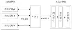
第一方面,本申请提供一种航天器微振动地面试验系统,包括传感器网络、中继器及工控计算机,所述中继器连接在传感器网络和工控计算机之间,所述中继器通过屏蔽电缆与传感器网络连接,中继器通过网线与工控计算机连接;所述传感器网络包括若干激光陀螺传感器,每个所述激光陀螺传感器分别通过屏蔽电缆与中继器连接;所述中继器包括电源系统、陀螺伺服组件及控制器;所述电源系统用于对中继器及传感器网络供电;所述陀螺伺服组件用于控制传感器网络中的各激光陀螺传感器。In a first aspect, the present application provides a spacecraft micro-vibration ground test system, including a sensor network, a repeater and an industrial control computer, the repeater is connected between the sensor network and the industrial control computer, and the repeater is shielded. The cable is connected to the sensor network, and the repeater is connected to the industrial control computer through a network cable; the sensor network includes several laser gyro sensors, and each of the laser gyro sensors is connected to the repeater through a shielded cable; the repeater includes a power supply A system, a gyro servo assembly and a controller; the power supply system is used to supply power to a repeater and a sensor network; the gyro servo assembly is used to control each laser gyro sensor in the sensor network.
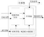
根据本申请实施例提供的技术方案,所述电源系统包括两级隔离,第一级隔离通过AC/DC开关电源将市电AC220V转换为24V直流,第二级隔离通过DC/DC开关电源将直流24V转换为陀螺伺服组件及激光陀螺传感器所需供电量。According to the technical solutions provided in the embodiments of the present application, the power supply system includes two levels of isolation, the first level of isolation converts the AC220V of the mains into 24V direct current through the AC/DC switching power supply, and the second level of isolation uses the DC/DC switching power supply to convert the direct current The 24V is converted into the power supply required by the gyro servo components and the laser gyro sensor.
根据本申请实施例提供的技术方案,所述陀螺伺服组件包括:高压稳流电源、稳频驱动电路、光强调理电路、模数转换器及数模转换器;所述高压稳流电源用于对传感器网络提供稳定的增益,且提供10-4量级对称度的恒流源;所述稳频驱动电路用于将数模转换器的输出电压放大以驱动传感器网络中的稳频执行机构;所述光强调理电路用于对传感器网络中输出的左、右旋激光陀螺传感器的光强信号进行求差或求和。According to the technical solutions provided in the embodiments of the present application, the gyro servo assembly includes: a high-voltage steady-current power supply, a frequency-stabilized drive circuit, a light intensity management circuit, an analog-to-digital converter, and a digital-to-analog converter; the high-voltage steady-current power supply is used for Provide a stable gain to the sensor network, and provide a constant current source with an order of magnitude of 10-4 symmetry; the frequency-stabilized drive circuit is used to amplify the output voltage of the digital-to-analog converter to drive the frequency-stabilized actuator in the sensor network; The light intensity management circuit is used for calculating the difference or summing the light intensity signals of the left- and right-handed laser gyro sensors output in the sensor network.
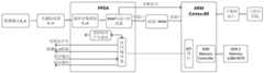
根据本申请实施例提供的技术方案,所述控制器用于采集传感器网络的数据,并将采集的数据发送至工控计算机;所述控制器包括FPGA模块与ARM模块,所述FPGA模块用于实时采集数据,所述ARM模块用于将采集的数据进行数据计算及传输。According to the technical solutions provided in the embodiments of the present application, the controller is used to collect data from the sensor network and send the collected data to an industrial computer; the controller includes an FPGA module and an ARM module, and the FPGA module is used for real-time collection data, the ARM module is used for data calculation and transmission of the collected data.
根据本申请实施例提供的技术方案,所述中继器包括壳体,所述电源系统、陀螺伺服组件及控制器集成在所述壳体内,所述壳体上分别设有TCP/IP接口、电源输入端口、手动开关、SMA同步接口、传感器连接端;TCP/IP接口通过网线与工控计算机连接;电源输入端口将市电AC220V接入所述电源系统;手动开关控制电源系统上电;SMA同步接口通过屏蔽电缆连接外部同步仪器;传感器连接端通过屏蔽电缆与各个激光陀螺传感器连接。According to the technical solutions provided by the embodiments of the present application, the repeater includes a casing, the power supply system, the gyro servo assembly and the controller are integrated in the casing, and the casing is respectively provided with a TCP/IP interface, Power input port, manual switch, SMA synchronization interface, sensor connection end; TCP/IP interface is connected with industrial computer through network cable; power input port connects AC220V mains to the power supply system; manual switch controls the power-on of the power supply system; SMA synchronization The interface is connected to the external synchronization instrument through a shielded cable; the sensor connection end is connected to each laser gyro sensor through a shielded cable.
第二方面,本申请提供一种航天器微振动地面试验方法,包括以下步骤:In a second aspect, the present application provides a method for a spacecraft micro-vibration ground test, comprising the following steps:
确定被测产品上要测量角位移的位置,在相应的各个位置上分别安装激光陀螺传感器;Determine the position on the product under test where the angular displacement is to be measured, and install the laser gyro sensor at each corresponding position;
将各个激光陀螺传感器通过屏蔽电缆连接至中继器;Connect each laser gyro sensor to the repeater through a shielded cable;
将中继器通过网线与工控计算机连接,工控计算机设置在远离被测产品的位置;Connect the repeater to the industrial control computer through a network cable, and the industrial control computer is set at a position far away from the product under test;
工控计算机开机,中继器上电;The industrial computer is turned on, and the repeater is powered on;
启动工控计算机上角位移测试软件,中继器控制传感器网络中的各个激光陀螺传感器启动工作,并采集各个激光陀螺传感器的测试数据,将采集数据发送至工控计算机;Start the angular displacement test software on the industrial control computer, the repeater controls each laser gyro sensor in the sensor network to start work, collects the test data of each laser gyro sensor, and sends the collected data to the industrial control computer;
关闭工控计算机上角位移测试软件,中继器控制传感器网络中的各个激光陀螺传感器停止工作;Close the angular displacement test software on the industrial computer, and the repeater controls each laser gyro sensor in the sensor network to stop working;
工控机将接收的中继器的发送的数据进行试验数据处理分析。The industrial computer processes and analyzes the data sent by the received repeater.
本申请提供中继器的技术方案与现有微振动角位移测量技术相比具有以下技术特点:Compared with the existing micro-vibration angular displacement measurement technology, the technical solution of the repeater provided by this application has the following technical characteristics:
1.设计了用于驱动激光陀螺传感器工作的中继器,实现陀螺高分辨率工作的伺服控制,而且中继器无噪声源,降低测试现场干扰;1. The repeater used to drive the laser gyro sensor is designed to realize the servo control of the high-resolution gyro operation, and the repeater has no noise source, reducing the interference on the test site;
2.中继器与工控计算机采用网线传输数据和控制信号,工控计算机远离被测星体,减少系统本体噪声,具有高抗干扰能力;2. The repeater and the industrial control computer use network cables to transmit data and control signals, and the industrial control computer is far away from the measured star, reducing the noise of the system itself, and has high anti-interference ability;
3.为了适应后续升级,该中继器装置可支持硬件扩展和软件功能扩展。3. In order to adapt to subsequent upgrades, the repeater device can support hardware expansion and software function expansion.
附图说明Description of drawings
图1为本申请第一种实施例的结构原理框图;Fig. 1 is the structural principle block diagram of the first embodiment of the application;
图2为本申请第一种实施例中中继器的结构原理框图;FIG. 2 is a structural principle block diagram of the repeater in the first embodiment of the application;
图3为本申请第一种实施例中中继器的电源系统的结构原理框图;FIG. 3 is a structural principle block diagram of the power supply system of the repeater in the first embodiment of the application;
图4为本申请第一种实施例中中继器的陀螺伺服组件的结构原理框图;Fig. 4 is the structural principle block diagram of the gyro servo assembly of the repeater in the first embodiment of the application;
图5为本申请第一种实施例中中继器的控制器的结构原理框图;FIG. 5 is a structural principle block diagram of the controller of the repeater in the first embodiment of the application;
图6为本申请第二种实施例的流程图。FIG. 6 is a flowchart of a second embodiment of the present application.
具体实施方式Detailed ways
为了使本领域技术人员更好地理解本发明的技术方案,下面结合附图对本申请进行详细描述,本部分的描述仅是示范性和解释性,不应对本申请的保护范围有任何的限制作用。In order to make those skilled in the art better understand the technical solutions of the present invention, the present application is described in detail below with reference to the accompanying drawings. The description in this part is only exemplary and explanatory, and should not have any limiting effect on the protection scope of the present application. .
如图1及图2所示为本申请的第一种实施例的示意图,包括传感器网络、中继器及工控计算机,所述中继器连接在传感器网络和工控计算机之间,所述中继器通过屏蔽电缆与传感器网络连接,中继器通过网线与工控计算机连接;所述传感器网络包括若干激光陀螺传感器,每个所述激光陀螺传感器分别通过屏蔽电缆与中继器连接;所述中继器包括电源系统、陀螺伺服组件及控制器;所述电源系统用于对中继器及传感器网络供电;所述陀螺伺服组件用于控制传感器网络中的各激光陀螺传感器。1 and 2 are schematic diagrams of the first embodiment of the application, including a sensor network, a repeater and an industrial computer, the repeater is connected between the sensor network and the industrial computer, and the relay The sensor network is connected to the sensor network through a shielded cable, and the repeater is connected to the industrial control computer through a network cable; the sensor network includes several laser gyro sensors, and each of the laser gyro sensors is connected to the repeater through a shielded cable; the relay The device includes a power supply system, a gyro servo component and a controller; the power supply system is used to supply power to the repeater and the sensor network; the gyro servo component is used to control each laser gyro sensor in the sensor network.
中继器中的控制器是中继器的控制中心,负责监控中继器的工作状态,控制对传感器网络中的各个激光陀螺传感器上电、控制采集各个激光陀螺传感器信号、控制信号上传、接收/发送同步信号等。The controller in the repeater is the control center of the repeater, which is responsible for monitoring the working status of the repeater, controlling the power-on of each laser gyro sensor in the sensor network, controlling the acquisition of each laser gyro sensor signal, and controlling the upload and reception of the signal. /Send sync signals, etc.
在一优选实施方式中,如图3所示,所述电源系统包括两级隔离,可以有效降低市电干扰,第一级隔离通过AC/DC开关电源将市电AC220V转换为24V直流,第二级隔离通过DC/DC开关电源将直流24V转换为陀螺伺服组件及激光陀螺传感器所需供电量。In a preferred embodiment, as shown in FIG. 3 , the power supply system includes two-level isolation, which can effectively reduce the mains interference. The first-level isolation converts the mains AC220V into 24V DC through the AC/DC switching power supply, and the second The high-level isolation converts the
本实施例中,电源系统的电源开关采用硬件开关与软件开关串联的结构,打开中继器面板上的硬件开关后,中继器内部的控制器上电,然后可通过测试软件控制软件开关的开启或关闭。In this embodiment, the power switch of the power supply system adopts a structure in which a hardware switch and a software switch are connected in series. After the hardware switch on the repeater panel is turned on, the controller inside the repeater is powered on, and then the software switch can be controlled by the test software. On or off.
在一优选实施方式中,如图4所示,所述陀螺伺服组件包括硬件部分及软件部分,硬件部分主要完成各电路的信号调理和功放,软件部分主要完成各反馈控制环路的闭环算法,且以DSP数字处理器芯片为硬件基础。In a preferred embodiment, as shown in Figure 4, the gyro servo assembly includes a hardware part and a software part, the hardware part mainly completes the signal conditioning and power amplifier of each circuit, and the software part mainly completes the closed-loop algorithm of each feedback control loop, And take DSP digital processor chip as the hardware foundation.
硬件部分包括:高压稳流电源、稳频驱动电路、光强调理电路、模数转换器及数模转换器。The hardware part includes: high voltage steady current power supply, frequency stabilization drive circuit, light intensity management circuit, analog-to-digital converter and digital-to-analog converter.
所述高压稳流电源用于对传感器网络提供稳定的增益,且提供10-4量级对称度的恒流源,用于抑制“朗缪尔效应项”引起的零偏。The high-voltage regulated current power supply is used to provide a stable gain to the sensor network, and a constant current source with an order of symmetry of 10-4 to suppress the zero offset caused by the "Langmuir effect term".
所述稳频驱动电路用于将数模转换器的输出电压放大以驱动激光陀螺传感器上的稳频执行机构以实现扫模、程长控制等功能。The frequency stabilization drive circuit is used to amplify the output voltage of the digital-to-analog converter to drive the frequency stabilization actuator on the laser gyro sensor to realize functions such as mode sweeping and range length control.
所述光强调理电路用于对传感器网络中的前置放大器输出的左、右旋激光陀螺传感器的光强信号进行求差或求和,其中光强差输出用于稳频控制,光强和输出用于激光陀螺传感器功率监控和光功率稳定控制。The light intensity management circuit is used for difference or summation of the light intensity signals of the left and right-handed laser gyro sensors output by the preamplifier in the sensor network, wherein the light intensity difference output is used for frequency stabilization control, and the light intensity summation The output is used for laser gyro sensor power monitoring and optical power stabilization control.
在一优选实施方式中,如图5所示,所述控制器用于采集传感器网络的数据,控制中继器的工作状态,并通过以太网接口与高速的工控计算机进行通信。本优选实施方式中,所述控制器采用FPGA模块加ARM模块的基础架构,FPGA模块用于实时采集数据,ARM模块用于将采集的数据进行数据计算及传输。In a preferred embodiment, as shown in FIG. 5 , the controller is used to collect data from the sensor network, control the working state of the repeater, and communicate with a high-speed industrial computer through an Ethernet interface. In this preferred embodiment, the controller adopts an infrastructure of an FPGA module plus an ARM module, the FPGA module is used for real-time data collection, and the ARM module is used for data calculation and transmission of the collected data.
本实施例中,所述中继器包括壳体,所述电源系统、陀螺伺服组件及控制器集成在所述壳体内,所述壳体上分别设有TCP/IP接口、电源输入端口、手动开关、SMA同步接口、传感器连接端。In this embodiment, the repeater includes a casing, the power supply system, the gyro servo assembly and the controller are integrated in the casing, and the casing is respectively provided with a TCP/IP interface, a power input port, a manual Switch, SMA synchronization interface, sensor connection.
TCP/IP接口通过网线与工控计算机连接;电源输入端口将市电AC220V接入壳体内的电源系统;手动开关控制电源系统上电与掉电;SMA同步接口通过屏蔽电缆连接外部需要同步的仪器;传感器连接端通过屏蔽电缆与各个激光陀螺传感器连接。The TCP/IP interface is connected with the industrial computer through the network cable; the power input port connects the AC220V mains power to the power supply system in the housing; the manual switch controls the power-on and power-off of the power supply system; the SMA synchronization interface connects the external instruments that need to be synchronized through a shielded cable; The sensor connection end is connected with each laser gyro sensor through a shielded cable.
如图6所示为本申请的第二种实施例的流程图,本实施例是利用第一种实施例的试验系统进行测试的试验方法,包括以下步骤:Figure 6 is a flow chart of the second embodiment of the application. This embodiment is a test method for testing by using the test system of the first embodiment, including the following steps:
S1、确定被测产品上要测量角位移的位置,在相应的各个位置上分别安装激光陀螺传感器。S1. Determine the position on the tested product where the angular displacement is to be measured, and install the laser gyro sensor at each corresponding position.
S2、将各个激光陀螺传感器通过屏蔽电缆连接至中继器。S2. Connect each laser gyro sensor to the repeater through a shielded cable.
本实施例中,如果需要测量数据与其他测量数据同步,用屏蔽电缆将中继器的SMA同步接口连接至其他数据的采集系统。In this embodiment, if the measurement data needs to be synchronized with other measurement data, a shielded cable is used to connect the SMA synchronization interface of the repeater to the acquisition system of other data.
S3、将中继器通过网线与工控计算机连接,工控计算机设置在远离被测产品的位置。S3. Connect the repeater to the industrial control computer through a network cable, and the industrial control computer is set at a position far away from the product under test.
S4、工控计算机开机,中继器上电。S4. The industrial computer is powered on, and the repeater is powered on.
S5、启动工控计算机上角位移测试软件,中继器控制传感器网络中的各个激光陀螺传感器启动工作,并采集各个激光陀螺传感器的测试数据,将采集数据发送至工控计算机。S5. Start the angular displacement test software on the industrial control computer, the repeater controls each laser gyro sensor in the sensor network to start work, collects the test data of each laser gyro sensor, and sends the collected data to the industrial control computer.
S6、关闭工控计算机上角位移测试软件,中继器控制传感器网络中的各个激光陀螺传感器停止工作。S6, close the angular displacement test software on the industrial computer, and the repeater controls each laser gyro sensor in the sensor network to stop working.
S7、工控机将接收的中继器的发送的数据进行试验数据处理分析。S7, the industrial computer performs experimental data processing and analysis on the data sent by the received repeater.
本文中应用了具体个例对本申请的原理及实施方式进行了阐述,以上实例的说明只是用于帮助理解本申请的方法及其核心思想。以上所述仅是本申请的优选实施方式,应当指出,由于文字表达的有限性,而客观上存在无限的具体结构,对于本技术领域的普通技术人员来说,在不脱离本申请原理的前提下,还可以做出若干改进、润饰或变化,也可以将上述技术特征以适当的方式进行组合;这些改进润饰、变化或组合,或未经改进将申请的构思和技术方案直接应用于其它场合的,均应视为本申请的保护范围。Specific examples are used herein to illustrate the principles and implementations of the present application, and the descriptions of the above examples are only used to help understand the methods and core ideas of the present application. The above are only the preferred embodiments of the present application. It should be pointed out that, due to the limited expression of words, there are objectively unlimited specific structures. For those of ordinary skill in the art, without departing from the principles of the present application However, several improvements, modifications or changes can also be made, and the above-mentioned technical features can also be combined in an appropriate manner; these improvements, modifications, or combinations, or the ideas and technical solutions of the application are directly applied to other occasions without improvement. shall be regarded as the protection scope of this application.
Claims (4)
Translated fromChinesePriority Applications (1)
| Application Number | Priority Date | Filing Date | Title |
|---|---|---|---|
| CN202011335361.3ACN112393866B (en) | 2020-11-25 | 2020-11-25 | Spacecraft micro-vibration ground test system and test method |
Applications Claiming Priority (1)
| Application Number | Priority Date | Filing Date | Title |
|---|---|---|---|
| CN202011335361.3ACN112393866B (en) | 2020-11-25 | 2020-11-25 | Spacecraft micro-vibration ground test system and test method |
Publications (2)
| Publication Number | Publication Date |
|---|---|
| CN112393866A CN112393866A (en) | 2021-02-23 |
| CN112393866Btrue CN112393866B (en) | 2022-10-11 |
Family
ID=74606319
Family Applications (1)
| Application Number | Title | Priority Date | Filing Date |
|---|---|---|---|
| CN202011335361.3AActiveCN112393866B (en) | 2020-11-25 | 2020-11-25 | Spacecraft micro-vibration ground test system and test method |
Country Status (1)
| Country | Link |
|---|---|
| CN (1) | CN112393866B (en) |
Citations (5)
| Publication number | Priority date | Publication date | Assignee | Title |
|---|---|---|---|---|
| CN102798459A (en)* | 2012-08-10 | 2012-11-28 | 上海卫星工程研究所 | Satellite ground micro-vibration test system |
| CN103471798A (en)* | 2013-09-26 | 2013-12-25 | 北京空间飞行器总体设计部 | Refrigerating machine micro-vibration physical simulation test processing system |
| CN103712759A (en)* | 2014-01-06 | 2014-04-09 | 北京卫星环境工程研究所 | Spacecraft whole-satellite micro-vibration mechanics environment ground test method |
| CN105415374A (en)* | 2015-12-24 | 2016-03-23 | 大连理工大学 | Mechanical hand transmission unit on-line fault diagnosis system based on synergetic measurement |
| CN106323338A (en)* | 2016-08-17 | 2017-01-11 | 中国船舶重工集团公司第七〇七研究所 | Testing system and method for automatically evaluating performance of laser gyroscopes |
Family Cites Families (6)
| Publication number | Priority date | Publication date | Assignee | Title |
|---|---|---|---|---|
| US5907491A (en)* | 1996-08-23 | 1999-05-25 | Csi Technology, Inc. | Wireless machine monitoring and communication system |
| US20130201316A1 (en)* | 2012-01-09 | 2013-08-08 | May Patents Ltd. | System and method for server based control |
| CN103791998A (en)* | 2012-10-29 | 2014-05-14 | 天津市电力公司 | Mobile noise detection system |
| CN103777232A (en)* | 2014-02-20 | 2014-05-07 | 武汉大学 | Deep rock mass rock blasting forecasting and early warning method based on blast vibration monitoring |
| CN105785351B (en)* | 2016-03-10 | 2017-12-19 | 中国人民解放军国防科学技术大学 | A kind of method and system that ranging is obscured based on satellite |
| CN110553810B (en)* | 2019-07-23 | 2021-02-09 | 北京控制工程研究所 | Satellite-borne variable-speed CMG micro-vibration noise suppression method |
- 2020
- 2020-11-25CNCN202011335361.3Apatent/CN112393866B/enactiveActive
Patent Citations (5)
| Publication number | Priority date | Publication date | Assignee | Title |
|---|---|---|---|---|
| CN102798459A (en)* | 2012-08-10 | 2012-11-28 | 上海卫星工程研究所 | Satellite ground micro-vibration test system |
| CN103471798A (en)* | 2013-09-26 | 2013-12-25 | 北京空间飞行器总体设计部 | Refrigerating machine micro-vibration physical simulation test processing system |
| CN103712759A (en)* | 2014-01-06 | 2014-04-09 | 北京卫星环境工程研究所 | Spacecraft whole-satellite micro-vibration mechanics environment ground test method |
| CN105415374A (en)* | 2015-12-24 | 2016-03-23 | 大连理工大学 | Mechanical hand transmission unit on-line fault diagnosis system based on synergetic measurement |
| CN106323338A (en)* | 2016-08-17 | 2017-01-11 | 中国船舶重工集团公司第七〇七研究所 | Testing system and method for automatically evaluating performance of laser gyroscopes |
Non-Patent Citations (1)
| Title |
|---|
| 激光陀螺电路的数字一体化及其实现;王国臣;《中国惯性技术学报》;20090630;第17卷(第03期);第370-373页* |
Also Published As
| Publication number | Publication date |
|---|---|
| CN112393866A (en) | 2021-02-23 |
Similar Documents
| Publication | Publication Date | Title |
|---|---|---|
| CN110108299B (en) | An online self-calibration system for silicon micromachined gyroscope scale factor | |
| CN109143942B (en) | Attitude sensor control system | |
| CN105373143B (en) | Large astronomical telescope high-precision control system and method for inhibiting wind load disturbance | |
| CN106404160B (en) | A metering system and method for a transmission line monitoring device in an on-site environment | |
| CN113968349B (en) | A photoelectric pod fixation and signal transmission device used on a sprinkler helicopter | |
| JP2015118088A (en) | Accessories and calibration method thereof | |
| CN111896098A (en) | A vibration signal embedded remote monitoring system | |
| CN112393866B (en) | Spacecraft micro-vibration ground test system and test method | |
| CN118689128A (en) | Rudder loading platform control system, rudder load simulation system and semi-physical simulation system | |
| CN1322662C (en) | Integrated device in low power dissipation for digital controlling magnetic bearing | |
| CN109343031A (en) | A kind of round trip flight second light comb frequency stabilization system for space absolute distance measurement | |
| CN111679693A (en) | A UAV Obstacle Avoidance Method Based on Magnetic Field Strength Detection | |
| CN104215319B (en) | Dynamic range adjustable differential interferometer and measuring method | |
| CN103149950A (en) | Inertia rate composite stable control system | |
| CN101183002A (en) | A Method of Reducing Power Consumption of Fiber Optic Gyroscope | |
| CN103023020B (en) | A kind of FACTS device clusters control system is with its control method | |
| CN108445289B (en) | High-voltage direct-current optical harmonic measurement device | |
| Gu et al. | Design and applicability analysis of independent double acquisition circuit of all-fiber optical current transformer | |
| CN114261525B (en) | Rudder deflection control and measurement system and method | |
| CN115628801A (en) | Laser measuring device based on DataSocket communication | |
| CN212807558U (en) | Transverse continuous measuring system based on fiber-optic gyroscope | |
| CN114674360A (en) | A GIS equipment shell expansion joint geometric attitude monitoring device and method | |
| CN110608761A (en) | An optical fiber interference device and method capable of eliminating associated amplitude modulation | |
| CN106197285A (en) | Optical fiber sensing system | |
| CN104898454A (en) | Space optical payload force disturbance simulation source actuator force control method |
Legal Events
| Date | Code | Title | Description |
|---|---|---|---|
| PB01 | Publication | ||
| PB01 | Publication | ||
| SE01 | Entry into force of request for substantive examination | ||
| SE01 | Entry into force of request for substantive examination | ||
| GR01 | Patent grant | ||
| GR01 | Patent grant |