CN112384716B - position-dependent shock absorber - Google Patents
position-dependent shock absorberDownload PDFInfo
- Publication number
- CN112384716B CN112384716BCN201980046322.0ACN201980046322ACN112384716BCN 112384716 BCN112384716 BCN 112384716BCN 201980046322 ACN201980046322 ACN 201980046322ACN 112384716 BCN112384716 BCN 112384716B
- Authority
- CN
- China
- Prior art keywords
- fluid
- valve
- shock absorber
- damper
- pneumatic spring
- Prior art date
- Legal status (The legal status is an assumption and is not a legal conclusion. Google has not performed a legal analysis and makes no representation as to the accuracy of the status listed.)
- Active
Links
Images


Classifications
- F—MECHANICAL ENGINEERING; LIGHTING; HEATING; WEAPONS; BLASTING
- F16—ENGINEERING ELEMENTS AND UNITS; GENERAL MEASURES FOR PRODUCING AND MAINTAINING EFFECTIVE FUNCTIONING OF MACHINES OR INSTALLATIONS; THERMAL INSULATION IN GENERAL
- F16F—SPRINGS; SHOCK-ABSORBERS; MEANS FOR DAMPING VIBRATION
- F16F9/00—Springs, vibration-dampers, shock-absorbers, or similarly-constructed movement-dampers using a fluid or the equivalent as damping medium
- F16F9/06—Springs, vibration-dampers, shock-absorbers, or similarly-constructed movement-dampers using a fluid or the equivalent as damping medium using both gas and liquid
- F16F9/063—Springs, vibration-dampers, shock-absorbers, or similarly-constructed movement-dampers using a fluid or the equivalent as damping medium using both gas and liquid comprising a hollow piston rod
- B—PERFORMING OPERATIONS; TRANSPORTING
- B62—LAND VEHICLES FOR TRAVELLING OTHERWISE THAN ON RAILS
- B62K—CYCLES; CYCLE FRAMES; CYCLE STEERING DEVICES; RIDER-OPERATED TERMINAL CONTROLS SPECIALLY ADAPTED FOR CYCLES; CYCLE AXLE SUSPENSIONS; CYCLE SIDE-CARS, FORECARS, OR THE LIKE
- B62K25/00—Axle suspensions
- B62K25/04—Axle suspensions for mounting axles resiliently on cycle frame or fork
- F—MECHANICAL ENGINEERING; LIGHTING; HEATING; WEAPONS; BLASTING
- F16—ENGINEERING ELEMENTS AND UNITS; GENERAL MEASURES FOR PRODUCING AND MAINTAINING EFFECTIVE FUNCTIONING OF MACHINES OR INSTALLATIONS; THERMAL INSULATION IN GENERAL
- F16F—SPRINGS; SHOCK-ABSORBERS; MEANS FOR DAMPING VIBRATION
- F16F9/00—Springs, vibration-dampers, shock-absorbers, or similarly-constructed movement-dampers using a fluid or the equivalent as damping medium
- F16F9/06—Springs, vibration-dampers, shock-absorbers, or similarly-constructed movement-dampers using a fluid or the equivalent as damping medium using both gas and liquid
- F16F9/08—Springs, vibration-dampers, shock-absorbers, or similarly-constructed movement-dampers using a fluid or the equivalent as damping medium using both gas and liquid where gas is in a chamber with a flexible wall
- F16F9/092—Springs, vibration-dampers, shock-absorbers, or similarly-constructed movement-dampers using a fluid or the equivalent as damping medium using both gas and liquid where gas is in a chamber with a flexible wall comprising a gas spring with a flexible wall provided between the tubes of a bitubular damper
- F—MECHANICAL ENGINEERING; LIGHTING; HEATING; WEAPONS; BLASTING
- F16—ENGINEERING ELEMENTS AND UNITS; GENERAL MEASURES FOR PRODUCING AND MAINTAINING EFFECTIVE FUNCTIONING OF MACHINES OR INSTALLATIONS; THERMAL INSULATION IN GENERAL
- F16F—SPRINGS; SHOCK-ABSORBERS; MEANS FOR DAMPING VIBRATION
- F16F9/00—Springs, vibration-dampers, shock-absorbers, or similarly-constructed movement-dampers using a fluid or the equivalent as damping medium
- F16F9/32—Details
- F16F9/48—Arrangements for providing different damping effects at different parts of the stroke
- F16F9/49—Stops limiting fluid passage, e.g. hydraulic stops or elastomeric elements inside the cylinder which contribute to changes in fluid damping
- F—MECHANICAL ENGINEERING; LIGHTING; HEATING; WEAPONS; BLASTING
- F16—ENGINEERING ELEMENTS AND UNITS; GENERAL MEASURES FOR PRODUCING AND MAINTAINING EFFECTIVE FUNCTIONING OF MACHINES OR INSTALLATIONS; THERMAL INSULATION IN GENERAL
- F16F—SPRINGS; SHOCK-ABSORBERS; MEANS FOR DAMPING VIBRATION
- F16F2238/00—Type of springs or dampers
- F16F2238/04—Damper
Landscapes
- Engineering & Computer Science (AREA)
- General Engineering & Computer Science (AREA)
- Mechanical Engineering (AREA)
- Fluid-Damping Devices (AREA)
Abstract
Description
Translated fromChinese技术领域technical field
本发明涉及用于车辆(诸如自行车和摩托车)的减震器。The present invention relates to shock absorbers for vehicles such as bicycles and motorcycles.
背景技术Background technique
减震器和阻尼系统用于对车辆(诸如汽车、摩托车或自行车)的车轮和底盘之间的相对运动进行阻尼。常规的减震器通常包括填充有阻尼流体(诸如液压油或气体)的工作气缸和布置在活塞杆上并可移动地布置在气缸中的活塞。活塞还通常被布置成将气缸分成第一工作室和第二工作室并且抵抗流体的阻力而在气缸中移动,这继而使得阻尼流体在阻尼气缸中移动。阻尼器可被布置在车辆底盘和车轮之间,以随着车辆行进而伸缩地移动,使得车轮和车辆的移动因此被在气缸中抵抗流体阻力而移动的活塞进行阻尼。在摩托车、自行车或山地自行车的具体情况下,阻尼器可以布置在前叉布置和/或后轮悬架中,在任一种情况下,相对于驾驶员对冲击和振动进行阻尼。Shock absorbers and damping systems are used to damp the relative motion between the wheels and chassis of a vehicle, such as a car, motorcycle or bicycle. Conventional shock absorbers generally include a working cylinder filled with a damping fluid, such as hydraulic oil or gas, and a piston arranged on a piston rod and movably arranged in the cylinder. The piston is also typically arranged to divide the cylinder into a first working chamber and a second working chamber and to move in the cylinder against the resistance of the fluid, which in turn causes the damping fluid to move in the damping cylinder. Dampers may be arranged between the vehicle chassis and the wheels to move telescopically as the vehicle travels, so that the movement of the wheels and the vehicle is thus damped by pistons in the cylinders that move against fluid resistance. In the specific case of a motorcycle, bicycle or mountain bike, the damper may be arranged in the front fork arrangement and/or the rear wheel suspension, in either case damping shocks and vibrations with respect to the driver.
此外,减震器可包括用于控制由于流体流过阻尼器而施加的阻尼力的装置。此类装置可包括不同类型的阀布置。减震器中使用的一种常见类型的阀是止回阀,即允许流体沿一个方向流动的阀。Additionally, the shock absorber may include means for controlling the damping force exerted by the fluid flowing through the damper. Such devices may include different types of valve arrangements. A common type of valve used in shock absorbers is a check valve, a valve that allows fluid to flow in one direction.
减震器通常包括阻尼器和弹簧,该弹簧被配置为迫使阻尼器朝向阻尼器的伸出位置,使得阻尼器可用于对冲击进行反复阻尼。一些减震器包括卷簧,而其他减震器包括气动弹簧。气动弹簧压缩气体介质,该气体介质在阻尼器压缩时被压缩,使得在气动弹簧内建立压力。然而,包括气动弹簧的减震器的问题是使它们小型、耐灰尘和尘土,并且易于使用。另一问题是如何使它们成为用户可调节的。具体问题是如何防止阻尼器在严重冲击时触底反弹。Shock absorbers typically include a damper and a spring configured to urge the damper toward an extended position of the damper so that the damper can be used to repeatedly dampen shocks. Some shocks include coil springs, while others include gas springs. A pneumatic spring compresses a gaseous medium, which is compressed when the damper is compressed, so that a pressure builds up within the pneumatic spring. However, the problem with shock absorbers including pneumatic springs is that they are small, dust and dirt resistant, and easy to use. Another problem is how to make them user adjustable. The specific question is how to prevent the damper from bottoming out on hard impacts.
发明内容SUMMARY OF THE INVENTION
因此,期望提供改善的减震器。具体地,减震器易于使用。Therefore, it is desirable to provide improved shock absorbers. In particular, the shock absorber is easy to use.
因此,本发明的第一方面涉及一种提供易于使用的减震器。该减震器包括阻尼器。该阻尼器包括气缸和布置在所述气缸中的活塞组件。该活塞组件将气缸分成压缩阻尼器室和回弹弹簧室。该减震器还包括与该压缩阻尼器室流体连接的气动弹簧。该活塞组件可在该气缸内在外部位置和内部位置之间移动。该阻尼器包括阀组件,该阀组件用于对该压缩阻尼器室与该气动弹簧之间的流体流动进行节流。该阀组件沿着该阻尼器的纵向中心轴线从该阻尼器的内端部分延伸到该压缩阻尼器室中。该活塞组件包括内部空间,该内部空间通向该压缩阻尼器室并且被配置为在内部操作行程范围下接纳并密封地接合该阀组件的远侧部分并且被配置为在移动超出该内部操作行程范围时与该阀组件脱离接合。该阀组件的该远侧部分与该内部空间之间的该密封接合将该压缩阻尼器室分成该内部空间内的内部容积和该活塞组件前方的外部容积。在阻尼器压缩时,活塞在气缸内移动,使得压缩阻尼器室的容积减小,同时回弹弹簧室的容积增大。因此,流体被迫离开压缩阻尼器室、通过阀组件并进入气动弹簧中。首先,活塞组件在外部操作行程范围内朝向内部操作行程范围行进。Accordingly, a first aspect of the present invention relates to providing a shock absorber that is easy to use. The shock absorber includes a damper. The damper includes a cylinder and a piston assembly disposed in the cylinder. The piston assembly divides the cylinder into a compression damper chamber and a rebound spring chamber. The shock also includes a pneumatic spring fluidly connected to the compression damper chamber. The piston assembly is movable within the cylinder between an outer position and an inner position. The damper includes a valve assembly for throttling fluid flow between the compression damper chamber and the pneumatic spring. The valve assembly extends from an inner end portion of the damper into the compression damper chamber along a longitudinal center axis of the damper. The piston assembly includes an interior space that opens into the compression damper chamber and is configured to receive and sealingly engage the distal portion of the valve assembly under an interior operating stroke range and is configured to move beyond the interior operating stroke out of engagement with the valve assembly. The sealing engagement between the distal portion of the valve assembly and the interior space divides the compression damper chamber into an interior volume within the interior space and an exterior volume in front of the piston assembly. As the damper compresses, the piston moves within the cylinder, causing the volume of the compression damper chamber to decrease while the volume of the rebound spring chamber increases. Consequently, fluid is forced out of the compression damper chamber, through the valve assembly, and into the pneumatic spring. First, the piston assembly travels within the outer operating stroke range toward the inner operating stroke range.
一旦活塞组件达到内部操作行程范围,内部空间接纳并密封地接合阀组件的远侧部分,使得内部容积和外部容积分离。分离的容积使得不同的流体压力能够作用于不同的容积。作用在内部容积中(即,内部空间内)的流体压力用于迫使活塞组件朝向其外部伸出位置,从而延迟阻尼器在内部操作行程范围下的压缩,从而减轻阻尼器的触底反弹。外部容积中的流体可以继续被迫通过与移动到内部操作范围之外时相同的流体通道流过阀组件。在阻尼器伸出时,气动弹簧迫使流体通过阀组件进入压缩阻尼器室中。Once the piston assembly reaches the inner operating range of travel, the inner space receives and sealingly engages the distal portion of the valve assembly such that the inner and outer volumes are separated. The separate volumes enable different fluid pressures to act on the different volumes. Fluid pressure acting in the interior volume (ie, within the interior space) acts to force the piston assembly toward its outer extended position, delaying compression of the damper over the interior operating range of travel, thereby mitigating damper bottoming. Fluid in the outer volume may continue to be forced through the valve assembly through the same fluid passages as when moved out of the inner operating range. When the damper is extended, the pneumatic spring forces fluid through the valve assembly into the compression damper chamber.
阀组件可设置有穿过该阀组件的第一流体通道,所述通道被配置为允许该内部容积与该气动弹簧之间的流体连通。第一流体通道使得流体能够在内部容积和气动弹簧之间流动,使得即使在压缩阻尼器室中使用基本上不可压缩的流体,阻尼器也可被压缩。通过调整第一流体通道的尺寸和长度,可控制通过第一流体通路的流体流动阻力,从而控制内部操作行程范围内(即,在触底反弹之前在压挤行程结束时)的阻尼特性。The valve assembly may be provided with a first fluid passage therethrough, the passage being configured to allow fluid communication between the interior volume and the pneumatic spring. The first fluid passage enables fluid to flow between the interior volume and the pneumatic spring so that the damper can be compressed even with substantially incompressible fluid in the compression damper chamber. By adjusting the size and length of the first fluid passage, the resistance to fluid flow through the first fluid passage can be controlled, thereby controlling the damping characteristics over the internal operating stroke range (ie, at the end of the compression stroke before bottoming out).
第一阀可以设置在该第一流体通道中,所述阀被配置为允许流体从该内部容积通过该第一流体通道流动到该气动弹簧并且防止流体沿相反方向流动。第一阀使得能够例如通过将阀朝向其关闭位置的适当偏置使得内部容积内需要一定的阈值压力以打开第一阀而在内部操作行程范围内控制压缩时的流体流动。同时,阀确保没有从气动弹簧通过第一流体通道流回到内部容积,因此能够单独控制从气动弹簧到内部容积的回流。A first valve may be provided in the first fluid passage, the valve configured to allow fluid flow from the interior volume through the first fluid passage to the pneumatic spring and prevent fluid flow in the opposite direction. The first valve enables control of fluid flow at compression over the internal operating stroke range, eg by appropriately biasing the valve towards its closed position such that a certain threshold pressure is required within the internal volume to open the first valve. At the same time, the valve ensures that there is no flow from the pneumatic spring back to the inner volume through the first fluid channel, so that the return flow from the pneumatic spring to the inner volume can be individually controlled.
该第一流体通道可以是沿着该阻尼器的纵向中心轴线的中心孔,并且其中该第一阀包括通过偏置构件(诸如卷簧)朝向该中心孔的座偏置的闭合构件。偏置构件提供预定偏置力以用于保持阀关闭,直到在阀上实现预定压差。具有沿纵向中心轴线的孔形式的第一通道的中心位置提供从内部容积流出的平衡流动,并且因此在活塞组件、气缸和阀组件之间提供低磨损和较少振动。The first fluid passage may be a central bore along a longitudinal center axis of the damper, and wherein the first valve includes a closure member biased toward the seat of the central bore by a biasing member, such as a coil spring. The biasing member provides a predetermined biasing force for holding the valve closed until a predetermined pressure differential across the valve is achieved. The central location of the first passage in the form of a hole along the longitudinal central axis provides balanced flow out of the interior volume and thus provides low wear and less vibration between the piston assembly, cylinder and valve assembly.
该阀组件可以设置有穿过该阀组件的第二流体通道,所述第二流体通道被配置为允许该内部容积与该气动弹簧之间的流体连通。第二流体通道使得能够在内部容积和气动弹簧之间流动。提供第一流体通道和第二流体通道两者使得能够实现比如果仅使用第一流体通道时更低的流动阻力。另外,当阀设置在第一流体通道中时,提供第二流体通道使得流体能够在与第一流体通道中的阀所允许的方向相反的方向上流动。允许流体从气动弹簧回流到内部容积使得气动弹簧能够迫使活塞组件从其压缩位置朝向其伸出位置。The valve assembly may be provided with a second fluid passage therethrough, the second fluid passage being configured to allow fluid communication between the interior volume and the pneumatic spring. The second fluid channel enables flow between the inner volume and the pneumatic spring. Providing both the first fluid channel and the second fluid channel enables a lower flow resistance than if only the first fluid channel were used. Additionally, when the valve is provided in the first fluid channel, providing the second fluid channel enables fluid to flow in a direction opposite to that permitted by the valve in the first fluid channel. Allowing fluid to flow back from the pneumatic spring to the interior volume enables the pneumatic spring to force the piston assembly from its compressed position toward its extended position.
该第二阀可以设置在该第二流体通道中,所述第二阀被配置为允许流体从该气动弹簧通过该第二流体通道流动到该内部容积并且防止流体沿相反方向流动。阀确保在阻尼器压缩时没有从内部容积通过第二流体通道到气动弹簧的流体流动,因此使得能够单独控制从内部容积分别通过第一流体通道和第二流体通道以及到内部容积的流体流动。具体地,各自设置有如本文所述的相应阀的第一流体通道和第二流体通道两者的组合是有利的,因为其在压缩行程和回弹行程两者下提供对从内部容积通过阀组件/通过阀组件到内部容积的流体流动的控制。该第二阀可包括垫片或垫片堆。垫片或垫片堆提供简单且稳健的阀。垫片或垫片堆还适用于限定第一流体通道从内部容积的开口。在压缩行程中,垫片抵靠阀组件的内端部分密封,并且因此防止流体从内部容积流入第二流体通道中。在回弹行程中,垫片在流体压力下弯曲,并且从而打开,使得流体可以从气动弹簧通过第二流体通道流入内部容积中。The second valve may be disposed in the second fluid passage, the second valve being configured to allow fluid flow from the pneumatic spring through the second fluid passage to the interior volume and prevent fluid flow in the opposite direction. The valve ensures that there is no fluid flow from the inner volume through the second fluid channel to the pneumatic spring when the damper is compressed, thus enabling separate control of fluid flow from the inner volume through the first and second fluid channels and to the inner volume, respectively. In particular, the combination of both the first fluid passage and the second fluid passage, each provided with a respective valve as described herein, is advantageous because it provides an advantage over the passage of the valve assembly from the interior volume under both the compression stroke and the rebound stroke. / Control of fluid flow through the valve assembly to the interior volume. The second valve may include a shim or stack of shims. Gaskets or shim stacks provide a simple and robust valve. The shim or stack of shims is also suitable for defining the opening of the first fluid passage from the interior volume. During the compression stroke, the gasket seals against the inner end portion of the valve assembly and thus prevents fluid flow from the inner volume into the second fluid passage. During the rebound stroke, the spacer flexes under fluid pressure and thereby opens so that fluid can flow from the pneumatic spring through the second fluid channel into the interior volume.
该阀组件可包括第三流体通道,该第三流体通道将该压缩阻尼器室的该外部容积流体连接到该气动弹簧。第三流体通道使得流体能够从外部容积流动到气动弹簧,使得即使在压缩阻尼器室中使用基本上不可压缩的流体,阻尼器也可被压缩。此外,第三流体通道使得能够从压缩阻尼器室通过阀组件流动到也在内部操作行程范围之外(即,也当阻尼器伸出时)的气动弹簧。The valve assembly may include a third fluid passage that fluidly connects the outer volume of the compression damper chamber to the pneumatic spring. The third fluid passage enables fluid to flow from the outer volume to the pneumatic spring so that the damper can be compressed even with substantially incompressible fluid in the compression damper chamber. Furthermore, the third fluid passage enables flow from the compression damper chamber through the valve assembly to the pneumatic spring also outside the internal operating stroke range (ie also when the damper is extended).
该第三流体通道可以设置有第三阀,所述第三阀被配置为允许流体从该外部容积通过该第三流体通道流动到该气动弹簧并且防止流体沿相反方向流动。第三阀确保在阻尼器松弛时没有从气动弹簧通过第三流体通道流回到外部容积。这使得能够分别在压缩和松弛时单独控制从气动弹簧到外部容积的流体流动,并且因此第三流体通道的流动阻力可以仅被设计用于压缩,而不需要考虑通过第三流体通道的回流。The third fluid passage may be provided with a third valve configured to allow fluid flow from the outer volume through the third fluid passage to the pneumatic spring and prevent fluid flow in the opposite direction. The third valve ensures that there is no flow from the pneumatic spring back to the outer volume through the third fluid passage when the damper is relaxed. This enables separate control of the fluid flow from the pneumatic spring to the outer volume in compression and relaxation, respectively, and thus the flow resistance of the third fluid channel can be designed for compression only, without considering the backflow through the third fluid channel.
该第一流体通道可以设置有第一用户可调节阀,该第一用户可调节阀用于限制通过该第一流体通道的流体流动,其中所述第一用户可调节阀包括操作构件,该操作构件能够从该阻尼器外部移动以用于通过该第一用户可调节阀调节该流动阻力。第一用户可调节阀使得用户能够通过增大或减小从压缩阻尼器室通过第一流体通道到气动弹簧的流体流动阻力(例如通过由第一操作构件的移动部分地阻塞第一流体通道的截面面积来调节第三流体通道的截面面积)来调节阻尼器在整个压缩行程中的压缩阻力。The first fluid passage may be provided with a first user adjustable valve for restricting fluid flow through the first fluid passage, wherein the first user adjustable valve includes an operating member that operates A member is movable from outside the damper for adjusting the flow resistance through the first user adjustable valve. The first user adjustable valve enables the user to increase or decrease the resistance to fluid flow from the compression damper chamber through the first fluid passage to the pneumatic spring (eg, by partially blocking the first fluid passage by movement of the first operating member). cross-sectional area to adjust the cross-sectional area of the third fluid passage) to adjust the compression resistance of the damper throughout the compression stroke.
该阀组件可包括第四流体通道,该第四流体通道将该压缩阻尼器室的该外部容积流体连接到该气动弹簧。第四流体通道使得能够在外部容积和气动弹簧之间流动。提供第三流体通道和第四流体通道两者使得能够实现比如果仅第三流体通道用于外部容积和气动弹簧之间的流体连通时更低的流动阻力。另外,当阀设置在第三流体通道中时,提供第四流体通道使得流体能够在与第三流体通道中的阀所允许的方向相反的方向上流动。允许此类流体从气动弹簧流动到外部容积使得气动弹簧能够迫使活塞组件从其压缩位置朝向其伸出位置。The valve assembly may include a fourth fluid passage that fluidly connects the outer volume of the compression damper chamber to the pneumatic spring. A fourth fluid channel enables flow between the outer volume and the pneumatic spring. Providing both the third fluid channel and the fourth fluid channel enables a lower flow resistance than if only the third fluid channel were used for fluid communication between the outer volume and the pneumatic spring. Additionally, when the valve is provided in the third fluid channel, the provision of the fourth fluid channel enables fluid to flow in a direction opposite to that permitted by the valve in the third fluid channel. Allowing such fluid to flow from the pneumatic spring to the outer volume enables the pneumatic spring to force the piston assembly from its compressed position towards its extended position.
该第四流体通道可以设置有第四阀,所述第四阀被配置为允许流体从气动弹簧通过第四流体通道流动到外部容积,并且防止流体沿相反方向流动。第四阀确保在阻尼器压缩时没有从外部容积通过第四流体通道到气动弹簧的流动。这使得能够单独控制分别在压缩和松弛时外部容积与气动弹簧之间的流体流动,因此第四流体通道的流动阻力可被设计用于松弛性能,并且第三流体通道的流动阻力被设计用于压缩性能。The fourth fluid passage may be provided with a fourth valve configured to allow fluid flow from the pneumatic spring through the fourth fluid passage to the external volume and prevent fluid flow in the opposite direction. The fourth valve ensures that there is no flow from the outer volume through the fourth fluid passage to the pneumatic spring when the damper is compressed. This enables separate control of the fluid flow between the outer volume and the pneumatic spring in compression and relaxation respectively, so the flow resistance of the fourth fluid channel can be designed for relaxation performance and the flow resistance of the third fluid channel is designed for Compression performance.
该第四流体通道可以设置有第二用户可调节阀,该第二用户可调节阀用于限制流体流过该第三流体通道,其中所述第二用户可调节阀包括操作构件,该操作构件能够从该阻尼器外部移动以用于通过该第一用户可调节阀调节该流动阻力。第二用户可调节阀使得用户能够通过增大或减小从气动弹簧通过第四流体通道到压缩阻尼器室的流体流动阻力(例如通过由第二操作构件的移动部分地阻塞第四流体通道的截面面积)调节阻尼器对从其压缩状态延伸到其伸出状态的阻力。The fourth fluid passage may be provided with a second user adjustable valve for restricting fluid flow through the third fluid passage, wherein the second user adjustable valve includes an operating member that It is movable from outside the damper for adjusting the flow resistance through the first user adjustable valve. The second user-adjustable valve enables the user to increase or decrease the resistance to fluid flow from the pneumatic spring through the fourth fluid passage to the compression damper chamber (eg, by partially blocking the fourth fluid passage by movement of the second operating member). cross-sectional area) adjusts the damper's resistance to extending from its compressed state to its extended state.
该活塞组件可通过该内部空间到该压缩阻尼器室的开口而设置有倒角引入部分。The piston assembly may be provided with a chamfered lead-in portion through the opening of the inner space to the compression damper chamber.
倒角引入部分在阻尼器压缩时将阀组件引导到内部空间中,从而减少阻尼器压缩时的磨损。The chamfered lead-in portion guides the valve assembly into the interior space when the damper is compressed, thereby reducing wear on the damper when it is compressed.
长形的、逐渐锥形化的狭槽设置在该活塞经过的管的该内表面的部分上。这具有以下优点:本发明在行程末端附近提供的额外阻尼力可在较长距离内逐渐增大。活塞越接近触底反弹位置,狭槽将越窄,从而提供阻尼力的逐渐增加。An elongated, gradually tapered slot is provided on the portion of the inner surface of the tube through which the piston passes. This has the advantage that the additional damping force provided by the present invention near the end of the stroke can be gradually increased over longer distances. The closer the piston is to bottoming out, the narrower the slot will be, providing a gradual increase in damping force.
附图说明Description of drawings
图1至14均涉及减震器的第一实施方案。1 to 14 all relate to a first embodiment of a shock absorber.
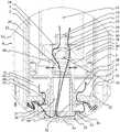
图1示出了如图3所限定的减震器的截面视图A-A。FIG. 1 shows a cross-sectional view A-A of the shock absorber as defined in FIG. 3 .
图2示出了如图1所限定的放大部分C,其着重于气动弹簧和阻尼器之间的连接。Figure 2 shows an enlarged section C as defined in Figure 1, focusing on the connection between the pneumatic spring and the damper.
图3示出了减震器的俯视图。Figure 3 shows a top view of the shock absorber.
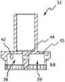
图4示出了如图1所限定的放大部分B,其着重于阀组件的流体通道。Figure 4 shows an enlarged portion B as defined in Figure 1, focusing on the fluid passages of the valve assembly.
图5和图6示出了中间件连同第三流体通道和第四流体通道的部分的俯视透视图和仰视透视图。Figures 5 and 6 show top and bottom perspective views of the intermediate piece together with portions of the third and fourth fluid channels.
图7和图8示出了端盖的透视图。7 and 8 show perspective views of the end cap.
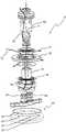
图9和图10分别示出了处于组装状态和分解状态的阀组件。9 and 10 show the valve assembly in an assembled state and an exploded state, respectively.
图11至图14示出了阀组件的基座件的各种视图。11-14 show various views of the base member of the valve assembly.
具体实施方式Detailed ways
根据第一实施方案的减震器1将在下文中参考附图进行描述。减震器1包括阻尼器和气动弹簧8。阻尼器包括气缸2和布置在所述气缸中的活塞组件3。在图1中,示出了不具有其上端配件的减震器1,该上端配件通常设置在活塞杆组件2上。上端配件密封活塞杆的上端并提供用于附接到车辆的孔眼,该孔眼类似于减震器1的下端中所示的孔眼。活塞组件3包括活塞杆4以及用于在气缸2和活塞杆4之间进行密封的密封件5。活塞组件3将气缸2分成压缩阻尼器室6和回弹弹簧室7。减震器1还包括与压缩阻尼器室6流体连接的气动弹簧8。活塞组件3可在气缸2内在外部位置和内部位置之间移动。The
阻尼器包括用于对压缩阻尼器室6和气动弹簧8之间的流体流进行节流的阀组件9。阀组件9从阻尼器的内端部分10延伸到压缩阻尼器室6中。该实施方案中的阀组件9沿着阻尼器的纵向中心轴线11延伸,但在其他实施方案中可以其他方式延伸,诸如偏离中心但平行于阻尼器的纵向轴线11。活塞组件3包括内部空间53,该内部空间通向压缩阻尼器室6并且被配置为在内部操作行程范围13下接纳并密封地接合阀组件9的远侧部分12,并且在移动到内部操作行程范围13之外(即,在外部操作行程范围14中)时与阀组件9脱离接合。内部操作行程范围13在图1中连同连接到活塞组件13的前部的虚线一起被指示以供参考。阀组件9的远侧部分12与活塞组件3的内部空间53之间的密封接合将压缩阻尼器室6分成内部空间53内的内部容积15和在活塞组件3前方的外部容积16。在阻尼器压缩时,活塞在气缸内移动,使得压缩阻尼器室的容积减小,同时回弹弹簧室的容积增大。因此,流体被迫离开压缩阻尼器室、通过阀组件并进入气动弹簧中。首先,活塞组件在外部操作行程范围内朝向内部操作行程范围行进。The damper includes a
一旦活塞组件达到内部操作行程范围,内部空间53接纳并密封地接合阀组件的远侧部分,使得内部容积和外部容积分离。分离的容积使得不同的流体压力能够作用于不同的容积。作用在内部容积中(即,内部空间53内)的流体压力用于迫使活塞组件朝向其外部伸出位置,从而延迟阻尼器在内部操作行程范围内的压缩,从而减轻阻尼器的触底反弹。外部容积中的流体可以继续被迫通过与移动到内部操作范围之外时相同的流体通道流过阀组件。在阻尼器伸出时,气动弹簧迫使流体通过阀组件进入压缩阻尼器室中。Once the piston assembly reaches the inner operating range of travel, the
阀组件9设置有穿过阀组件9的第一流体通道17,所述第一流体通道17被配置为允许内部容积15和气动弹簧8之间的流体连通。通过在内部容积15和气动弹簧8之间延伸的流体通道、通过形成一个或多个孔、通道和/或室、从而引导流体来实现此类流体连通。相同的逻辑适用于实现允许通过阀组件9流体连通的其它通道。The
第一流体通道17使得流体能够在内部容积15和气动弹簧8之间流动。当流体被迫从阻尼器进入气动弹簧8时,气动弹簧8的柔性膜29变形以容纳从压缩阻尼器室6接纳的流体。当柔性膜29变形时,周围压力室(也称为压缩弹簧室53)中的气体(诸如空气)被压缩。The
第一阀18设置在第一流体通道17中。第一阀18被配置为允许流体从内部容积15通过第一流体通道17流动到气动弹簧8,并且防止流体沿相反方向流动。第一阀18确保没有流体从气动弹簧通过第一流体通道17回流到内部容积。通过这样防止流体回流,可通过阻尼器中的任何其他流体通道、具体地通过如下所述的第二流体通道23单独控制流体的此类回流。The
第一流体通道17包括沿着阻尼器的纵向中心轴线11的中心孔19。在其他实施方案中,中心孔可以其他方式定位(诸如偏心),只要其功能保持相同。第一阀18包括通过作为卷簧的偏置构件22朝向中心孔19的座21偏置的闭合构件20。在其它实施方案中,偏置构件22可为任何其它合适的偏置构件22,诸如片簧或弹性材料(诸如橡胶)件。座是中心孔19的内端的倒角部分,但是座的其他配置也可以替代地使用,这取决于期望的特性,例如允许泄漏流动的锋利边缘或锯齿状边缘。偏置构件提供预定偏置力以用于保持阀关闭,直到在阀上实现预定压差。具有沿纵向中心轴线的孔形式的第一通道的中心位置提供从内部容积流出的平衡流动,并且因此在活塞组件、气缸和阀组件之间提供低磨损和较少振动。The
阀组件9还设置有通过阀组件9的上述第二流体通道23,所述第二流体通道23被配置为允许内部容积15和气动弹簧8之间的流体连通。第二流体通道使得能够在内部容积和气动弹簧之间流动。另外,提供第二流体通道使得流体能够在与第一流体通道中的阀所允许的方向相反的方向上流动。允许流体从气动弹簧回流到内部容积使得气动弹簧能够通过增加内部容积中的流体压力来迫使活塞组件从其压缩位置朝向其伸出位置。The
另外,第二阀24设置在第二流体通道23中。第二阀24被配置为允许流体从气动弹簧8通过第二流体通道23流动到内部容积15,并且防止流体沿相反方向流动。第二阀确保在阻尼器压缩时没有流体从内部容积通过第二流体通道流动到气动弹簧。各自设置有如本文所述的相应阀的第一流体通道和第二流体通道两者的组合是有利的,因为该组合在压缩行程和回弹行程两者时提供对通过阀组件到内部容积/从内部容积通过阀组件的流体流动的控制。例如,相应的第一流体通道和第二流体通道的尺寸可以不同,以为相应的第一阀和第二阀允许的不同流体流动提供期望的流动特性。In addition, a
第二阀24包括垫片或垫片堆。垫片或垫片堆通过卷簧或锁环(未示出)保持就位,但在其他实施方案中,可替代地使用用于保持垫片或垫片堆定位的任何常规装置。垫片或垫片堆提供简单且稳健的阀。垫片或垫片堆还适用于限定第一流体通道从内部容积的开口。在压缩行程中,垫片抵靠阀组件的内端部分密封,并且因此防止流体从内部容积流入第二流体通道中。在回弹行程中,垫片在流体压力下弯曲,并且从而打开,使得流体可以从气动弹簧通过第二流体通道流入内部容积中。The
阀组件9包括将压缩阻尼器室6的外部容积16流体连接到气动弹簧8的第三流体通道25。第三流体通道使得流体能够从外部容积流动到气动弹簧。此外,即使压缩阻尼器室中的流体压力将低于阈值压力(在该阈值压力下,第一阀打开使得第一流体通道保持被第一阀关闭),第三流体通道也能够从压缩阻尼器室通过阀组件流动到也在内部操作行程范围之外的气动弹簧。The
第三流体通道25设置有第三阀26。第三阀被配置为允许流体从外部容积16通过第三流体通道25流动到气动弹簧8,并且防止流体沿相反方向流动。第三阀确保在阻尼器松弛时没有从气动弹簧通过第三流体通道流回到外部容积。这使得能够分别在压缩和松弛时单独控制从气动弹簧到外部容积的流体流动,并且因此第三流体通道的流动阻力可以仅被设计用于压缩,而不需要考虑通过第三流体通道的回流。The third
阀组件还包括第四流体通道27,该第四流体通道将压缩阻尼器室6的外部容积16流体连接到气动弹簧8。第四流体通道使得能够在外部容积和气动弹簧之间流动。提供第三流体通道和第四流体通道两者使得能够实现比如果仅第三流体通道用于外部容积和气动弹簧之间的流体连通时更低的流动阻力。另外,当阀设置在第三流体通道中时,提供第四流体通道使得流体能够在与第三流体通道中的阀所允许的方向相反的方向上流动。允许此类流体从气动弹簧流动到外部容积使得气动弹簧能够迫使活塞组件从其压缩位置朝向其伸出位置。The valve assembly also includes a
第四流体通道27设置有第四阀28。第四阀28被配置为允许流体从气动弹簧8通过第四流体通道27流动到外部容积16,并且防止流体沿相反方向流动。第四阀确保在阻尼器压缩时没有从外部容积通过第四流体通道到气动弹簧的流动。这使得能够单独控制分别在压缩和松弛时外部容积与气动弹簧之间的流体流动,因此第四流体通道的流动阻力可被设计用于松弛性能,并且第三流体通道的流动阻力被设计用于压缩性能。The
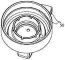
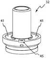
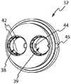
图9和图10示出了阀组件9连同以虚线示出的气动弹簧8的固定环30。固定环30用于保持柔性膜29相对于气动弹簧8的壳体52正确地定位。固定环30迫使柔性膜29的周向突起进入壳体52的内周上的对应凹部中。另外,固定环30设置有多个贯通流体通道孔31,该多个流体通道孔被配置为允许流体在阀组件和气动弹簧8之间来回通过。流体通道孔31中的一些流体通道孔由图10中的附图标号31例示。阀组件9包括构造成以下三个件的主体:基座件32、中间件33和远侧件34。第一流体通道17、第二流体通道23、第三流体通道25和第四流体通道27设置为通过主体,如图所示和本文所述。基座件32和远侧件34通过螺纹连接(未在图中示出的螺纹)接合。基座件和远侧件一起限定长形体,该长形体沿纵向中心轴线11居中延伸穿过气缸。中间件33以如图5和图6所示所示的盘状构件的形式提供。中间件33设置在长形体上,使得中间件适当地密封到气缸和由基座件和远侧件形成的长形体,从而将外部容积划分成面向活塞组件的第一容积35和与气动弹簧8流体连通的第二容积36。第三流体通道25和第四流体通道27设置为穿过中间件33,以控制第一容积35和第二容积36之间的流体流动。中心通路37设置为穿过由基座件32和远侧件34限定的长形体。基座件32设置有从中心通路37通向第一阀凹部38的孔。第一阀凹部38通过第五阀40流体连接到第二容积36,该第五阀被配置为允许流体从第一阀凹部38流动到第二容积并且防止流体沿相反方向流动。第五阀40包括两个压力分配室41,这两个压力分配室以弧形凹部的形式设置在基座件32中,每个压力分配室41由垫片或垫片堆43界定。每个压力分配室41经由相应的流体通道42流体连接到第一阀凹部38,如图4、图10和图12至图14所示。基座件32还设置有通过第一阀凹部38和第二阀凹部39之间的通道44流体连接到第一阀凹部38的第二阀凹部39,如图4、图9和图13所示。第二阀凹部39通过通道45流体连接到第二容积36。出于制造原因提供了辅助孔46,以便能够钻出第一阀凹部38和第二阀凹部39之间的通道。第一节流体47设置在第一阀凹部38内。第二节流体48设置在第二阀凹部38内。Figures 9 and 10 show the
第二节流体始终防止流体流过辅助孔。第一节流体和第二节流体具有不同尺寸的径向孔,该径向孔可被转动,使得每个节流体的一个此类径向孔与到相应的第一阀凹部和第二阀凹部的对应的入口/出口通道对准,从而调节流动阻力。第一节流体主要被提供以调节压缩流动阻力。第二节流体主要被提供以调节从气动弹簧到阻尼器的回流阻力。The second section of fluid prevents fluid flow through the auxiliary hole at all times. The first throttle body and the second throttle body have radial holes of different sizes that can be rotated such that one such radial hole of each throttle body corresponds to the corresponding first valve recess and second valve recess The corresponding inlet/outlet channels are aligned to adjust the flow resistance. The first throttle is primarily provided to adjust the compression flow resistance. The second throttle is primarily provided to adjust the return resistance from the pneumatic spring to the damper.
阀组件保持就位在气缸2和端盖51之间,如图1、图2、图7和图8所示。端盖51设置有凹部和通道,第一节流体47和第二节流体48延伸穿过该凹部和通道,使得它们可由减震器1的用户触及以进行操作。The valve assembly is held in place between the
另外,主体在中心通路37与压缩阻尼器室6的外部容积16之间设置有径向通道49。在其他实施方案中,可另选地省略径向通道。径向通道49在活塞组件3的所有位置处提供压缩阻尼器室的外部容积与中心通路之间的基本上不受限制的流体流动。In addition, the body is provided with
因此,在从伸出位置压缩时,在内部操作范围13之外,压缩阻尼器室6中的流体以缓慢移动按路径传送通过径向通道49并通过第一节流体47离开。在较高的移动速度下,通过第三流体通道25的流体流动随着垫片堆26偏转而增加。因此,在较高的移动速度下,存在两个基本上平行的流动,一个由垫片堆控制,另一个由第一节流体控制。Therefore, when compressed from the extended position, outside the
在压缩时,一旦活塞组件3达到其内部操作范围13并且如上所述抵靠阀组件9密封,活塞组件3内的内部容积15中的流体被迫通过第一流体通道17。Upon compression, once the
在松弛时,气动弹簧8内部的气体压力迫使流体流出气动弹簧8。气动弹簧8中的气体压力可通过使用气体端口50(参见图7和图8)增加或减少存在于气动弹簧8中的气体的量来调节,该气体端口设置有任何合适类型的阀(图中未示出阀,但是存在阀)。When relaxed, the gas pressure inside the
在该实施方案中,回弹弹簧室填充有气体,并且回弹弹簧室与压缩阻尼器室密封,使得在任何时候都没有阻尼流体按路径传送至回弹弹簧室。在其他实施方案中,可另选地通过提供通路和阀来将油按路径传送进出阻尼器的回弹弹簧室。In this embodiment, the rebound spring chamber is filled with gas, and the rebound spring chamber is sealed from the compression damper chamber such that no damping fluid is routed to the rebound spring chamber at any time. In other embodiments, oil may alternatively be routed in and out of the rebound spring chamber of the damper by providing passages and valves.
通常,气体端口50设置有通常可获得的阀,诸如Dunlop型阀、Shrader型阀或Presta型阀,从而使得能够使用通常可获得的工具容易地将气体注入气体室中。Typically, the
活塞组件3可通过内部空间53到压缩阻尼器室的开口而设置有倒角或以其他方式加宽的引入部分。虽然该实施方案中的活塞组件3被提供为一个主体,但另选地,该活塞组件可被配置为多个单独部件,这些部件通过密封到气缸以及在内部操作范围内也密封到阀组件而以与所公开的活塞组件相同的方式接合以起作用。与气缸2的内径相比,活塞组件的内部空间53的内径相对较大的减震器的设计允许在内部容积内建立流体压力,该流体压力以相对较大的力作用以迫使活塞组件在压缩行程结束时向外,从而减轻阻尼器的触底反弹。这使得能够在压缩行程结束时通过调节第一流体通道的延伸穿过阀组件的远侧部分12和任何相关联阀18的部分的流动阻力来实现宽范围的阻尼特性。The
在压缩阻尼器室中设置液体阻尼介质/流体。在其他实施方案中,可另选地使用一些其他合适的阻尼流体。A liquid damping medium/fluid is provided in the compression damper chamber. In other embodiments, some other suitable damping fluid may alternatively be used.
减震器1可用于山地自行车,例如安装到后轮悬架。The
应当理解,上文教导的流体通道中的一个或多个流体通道可另选地单独或组合提供,这取决于减震器1的预期阻尼特性和阻尼介质/流体(诸如液体或气体)的选择。此外,根据例如减震器的尺寸要求,每个流体通道的设计和按路径传送可以如本领域中已知的许多不同方式实现。此外,虽然所述实施方案中的气动弹簧8围绕阻尼器的气缸设置,但是另选地,在其他实施方案中,可替代地使用气动弹簧的其他配置,诸如流体连接到阻尼器的单独的气动弹簧,以与阀组件协作以用于类似的功能。It will be appreciated that one or more of the fluid passages taught above may alternatively be provided alone or in combination, depending on the desired damping characteristics of the
Claims (15)
Translated fromChineseApplications Claiming Priority (3)
| Application Number | Priority Date | Filing Date | Title |
|---|---|---|---|
| EP18183440.9AEP3594529B1 (en) | 2018-07-13 | 2018-07-13 | Position-dependent shock absorber |
| EP18183440.9 | 2018-07-13 | ||
| PCT/EP2019/068894WO2020012019A1 (en) | 2018-07-13 | 2019-07-12 | Position-dependent shock absorber |
Publications (2)
| Publication Number | Publication Date |
|---|---|
| CN112384716A CN112384716A (en) | 2021-02-19 |
| CN112384716Btrue CN112384716B (en) | 2022-07-12 |
Family
ID=62951947
Family Applications (1)
| Application Number | Title | Priority Date | Filing Date |
|---|---|---|---|
| CN201980046322.0AActiveCN112384716B (en) | 2018-07-13 | 2019-07-12 | position-dependent shock absorber |
Country Status (4)
| Country | Link |
|---|---|
| US (1) | US11592074B2 (en) |
| EP (1) | EP3594529B1 (en) |
| CN (1) | CN112384716B (en) |
| WO (1) | WO2020012019A1 (en) |
Families Citing this family (1)
| Publication number | Priority date | Publication date | Assignee | Title |
|---|---|---|---|---|
| US11479072B2 (en)* | 2020-09-29 | 2022-10-25 | GM Global Technology Operations LLC | Top mount with integrated jounce damper |
Citations (4)
| Publication number | Priority date | Publication date | Assignee | Title |
|---|---|---|---|---|
| FR2473144A1 (en)* | 1980-01-04 | 1981-07-10 | Fournales France Sarl | COMBINED SHOCK AND SUSPENSION DEVICE FOR VEHICLE |
| CN1836205A (en)* | 2003-08-12 | 2006-09-20 | 格雷姆·K·罗伯逊 | Shock absorber assembly |
| CN103119321A (en)* | 2010-08-12 | 2013-05-22 | 格雷姆·克肖·罗伯特森 | Improvements to the shock absorber |
| JP6224874B1 (en)* | 2017-03-07 | 2017-11-01 | 株式会社ショーワ | suspension |
Family Cites Families (7)
| Publication number | Priority date | Publication date | Assignee | Title |
|---|---|---|---|---|
| US2107494A (en)* | 1935-10-15 | 1938-02-08 | Onions | Shock absorbent strut for aircraft |
| DE1264879B (en)* | 1966-04-27 | 1968-03-28 | Stabilus Ind Und Handelsgesell | Gas spring for height and tilt adjustable items |
| DE3406976A1 (en)* | 1984-02-25 | 1985-09-12 | Daimler-Benz Ag, 7000 Stuttgart | VIBRATION DAMPER |
| FR2818029B1 (en)* | 2000-12-12 | 2003-04-04 | Carrier Kheops Bac | TIMED AUTOMATIC CLOSING COVER, PARTICULARLY FOR ELECTRICAL CONNECTOR, CYLINDER ELEMENT FOR CLOSING AND CORRESPONDING ELECTRICAL CONNECTOR |
| US8336683B2 (en)* | 2008-05-09 | 2012-12-25 | Specialized Bicycle Components, Inc. | Bicycle damper |
| WO2014165951A1 (en)* | 2013-04-10 | 2014-10-16 | Magneti Marelli Cofap Companhia Fabricadora De Peças | Hydraulic shock absorber for suspension system and corresponding improved hydraulic stop |
| EP2921740B1 (en)* | 2014-02-13 | 2018-07-11 | Abain Components, S.L. | Gas cylinder with a braking effect at the maximum extension |
- 2018
- 2018-07-13EPEP18183440.9Apatent/EP3594529B1/enactiveActive
- 2019
- 2019-07-12CNCN201980046322.0Apatent/CN112384716B/enactiveActive
- 2019-07-12USUS17/259,809patent/US11592074B2/enactiveActive
- 2019-07-12WOPCT/EP2019/068894patent/WO2020012019A1/ennot_activeCeased
Patent Citations (5)
| Publication number | Priority date | Publication date | Assignee | Title |
|---|---|---|---|---|
| FR2473144A1 (en)* | 1980-01-04 | 1981-07-10 | Fournales France Sarl | COMBINED SHOCK AND SUSPENSION DEVICE FOR VEHICLE |
| US4428567A (en)* | 1980-01-04 | 1984-01-31 | Fournales France | Combined shock absorbent and suspension for vehicle |
| CN1836205A (en)* | 2003-08-12 | 2006-09-20 | 格雷姆·K·罗伯逊 | Shock absorber assembly |
| CN103119321A (en)* | 2010-08-12 | 2013-05-22 | 格雷姆·克肖·罗伯特森 | Improvements to the shock absorber |
| JP6224874B1 (en)* | 2017-03-07 | 2017-11-01 | 株式会社ショーワ | suspension |
Also Published As
| Publication number | Publication date |
|---|---|
| CN112384716A (en) | 2021-02-19 |
| EP3594529C0 (en) | 2023-10-11 |
| US11592074B2 (en) | 2023-02-28 |
| US20210140508A1 (en) | 2021-05-13 |
| EP3594529A1 (en) | 2020-01-15 |
| EP3594529B1 (en) | 2023-10-11 |
| WO2020012019A1 (en) | 2020-01-16 |
Similar Documents
| Publication | Publication Date | Title |
|---|---|---|
| US20240109384A1 (en) | Shock absorber | |
| US8794404B2 (en) | Hydraulic shock absorber | |
| CN104379960B (en) | Dual-range damping system for shock absorbers | |
| US11473644B2 (en) | Front fork position-dependent damping for bicycles and motorcycles | |
| US10145438B2 (en) | Shock absorber | |
| CN102057180A (en) | Nested one-way high-speed valve | |
| CN101809312A (en) | Disc spring intake | |
| CN101305204A (en) | buffer | |
| CN107850170A (en) | Damper | |
| US20010009214A1 (en) | Hydraulic damper for suspension systems | |
| EP3409972A1 (en) | Pressurized telescopic front fork leg, front fork and vehicle | |
| JP6391512B2 (en) | Pressure shock absorber | |
| CN112384716B (en) | position-dependent shock absorber | |
| JP6047035B2 (en) | Hydraulic shock absorber for vehicles | |
| US10851903B2 (en) | Check valve assembly | |
| US11236799B2 (en) | Valve assembly for a damper | |
| JP5307739B2 (en) | Buffer valve structure | |
| JP2007271065A (en) | Hydraulic shock absorber | |
| JP2009008149A (en) | Damping force adjustable hydraulic shock absorber | |
| EP3848610A1 (en) | A shock absorber with gas spring and no gas-to-gas seals | |
| WO2025142278A1 (en) | Shock absorber | |
| CN120813785A (en) | Damper and front fork | |
| WO2024190240A1 (en) | Damper and front fork | |
| JP2024129779A (en) | Damper and front fork |
Legal Events
| Date | Code | Title | Description |
|---|---|---|---|
| PB01 | Publication | ||
| PB01 | Publication | ||
| SE01 | Entry into force of request for substantive examination | ||
| SE01 | Entry into force of request for substantive examination | ||
| GR01 | Patent grant | ||
| GR01 | Patent grant |