CN112368043B - Guide wire and method of manufacturing guide wire - Google Patents
Guide wire and method of manufacturing guide wireDownload PDFInfo
- Publication number
- CN112368043B CN112368043BCN201880095113.0ACN201880095113ACN112368043BCN 112368043 BCN112368043 BCN 112368043BCN 201880095113 ACN201880095113 ACN 201880095113ACN 112368043 BCN112368043 BCN 112368043B
- Authority
- CN
- China
- Prior art keywords
- diameter portion
- small
- mandrel
- small diameter
- covering member
- Prior art date
- Legal status (The legal status is an assumption and is not a legal conclusion. Google has not performed a legal analysis and makes no representation as to the accuracy of the status listed.)
- Active
Links
Images


Classifications
- A—HUMAN NECESSITIES
- A61—MEDICAL OR VETERINARY SCIENCE; HYGIENE
- A61M—DEVICES FOR INTRODUCING MEDIA INTO, OR ONTO, THE BODY; DEVICES FOR TRANSDUCING BODY MEDIA OR FOR TAKING MEDIA FROM THE BODY; DEVICES FOR PRODUCING OR ENDING SLEEP OR STUPOR
- A61M25/00—Catheters; Hollow probes
- A61M25/01—Introducing, guiding, advancing, emplacing or holding catheters
- A61M25/09—Guide wires
- A61M2025/09058—Basic structures of guide wires
- A61M2025/09083—Basic structures of guide wires having a coil around a core
- A—HUMAN NECESSITIES
- A61—MEDICAL OR VETERINARY SCIENCE; HYGIENE
- A61M—DEVICES FOR INTRODUCING MEDIA INTO, OR ONTO, THE BODY; DEVICES FOR TRANSDUCING BODY MEDIA OR FOR TAKING MEDIA FROM THE BODY; DEVICES FOR PRODUCING OR ENDING SLEEP OR STUPOR
- A61M25/00—Catheters; Hollow probes
- A61M25/01—Introducing, guiding, advancing, emplacing or holding catheters
- A61M25/09—Guide wires
- A61M2025/09108—Methods for making a guide wire
- A—HUMAN NECESSITIES
- A61—MEDICAL OR VETERINARY SCIENCE; HYGIENE
- A61M—DEVICES FOR INTRODUCING MEDIA INTO, OR ONTO, THE BODY; DEVICES FOR TRANSDUCING BODY MEDIA OR FOR TAKING MEDIA FROM THE BODY; DEVICES FOR PRODUCING OR ENDING SLEEP OR STUPOR
- A61M25/00—Catheters; Hollow probes
- A61M25/01—Introducing, guiding, advancing, emplacing or holding catheters
- A61M25/09—Guide wires
- A61M2025/09133—Guide wires having specific material compositions or coatings; Materials with specific mechanical behaviours, e.g. stiffness, strength to transmit torque
- A—HUMAN NECESSITIES
- A61—MEDICAL OR VETERINARY SCIENCE; HYGIENE
- A61M—DEVICES FOR INTRODUCING MEDIA INTO, OR ONTO, THE BODY; DEVICES FOR TRANSDUCING BODY MEDIA OR FOR TAKING MEDIA FROM THE BODY; DEVICES FOR PRODUCING OR ENDING SLEEP OR STUPOR
- A61M25/00—Catheters; Hollow probes
- A61M25/01—Introducing, guiding, advancing, emplacing or holding catheters
- A61M25/09—Guide wires
- A61M2025/09191—Guide wires made of twisted wires
- A—HUMAN NECESSITIES
- A61—MEDICAL OR VETERINARY SCIENCE; HYGIENE
- A61M—DEVICES FOR INTRODUCING MEDIA INTO, OR ONTO, THE BODY; DEVICES FOR TRANSDUCING BODY MEDIA OR FOR TAKING MEDIA FROM THE BODY; DEVICES FOR PRODUCING OR ENDING SLEEP OR STUPOR
- A61M2205/00—General characteristics of the apparatus
- A61M2205/02—General characteristics of the apparatus characterised by a particular materials
- A61M2205/0266—Shape memory materials
Landscapes
- Health & Medical Sciences (AREA)
- Life Sciences & Earth Sciences (AREA)
- Biophysics (AREA)
- Pulmonology (AREA)
- Engineering & Computer Science (AREA)
- Anesthesiology (AREA)
- Biomedical Technology (AREA)
- Heart & Thoracic Surgery (AREA)
- Hematology (AREA)
- Animal Behavior & Ethology (AREA)
- General Health & Medical Sciences (AREA)
- Public Health (AREA)
- Veterinary Medicine (AREA)
- Media Introduction/Drainage Providing Device (AREA)
Abstract
Description
Translated fromChinese技术领域technical field
本发明涉及一种导丝及制造导丝的方法。The invention relates to a guide wire and a method for manufacturing the guide wire.
背景技术Background technique
将导管等插入血管时使用的导丝,为人所熟知。这样的导丝,要求具备:对弯曲的柔软性、复原性、将近手部分的对导丝的操作传递到前端侧的扭矩传递性和推入性、以及对弯折、扭曲、压溃导致的变形抵抗性较强的强抗扭结性。另外,将扭矩传递性和推入性总称为“操作性”。例如,在专利文献1~3中公开的导丝中,通过设有配置在前端侧的第一芯轴(第一丝)、配置在第一芯轴的基端侧并与第一芯轴接合的第二芯轴(第二丝)以及覆盖第一及第二芯轴的接合部的包覆构件(管状构件),来提高柔软性和操作性。A guide wire used for inserting a catheter or the like into a blood vessel is well known. Such a guide wire is required to have flexibility and resilience against bending, torque transmission and pushability to transmit the operation of the guide wire near the hand to the front end side, and resistance to bending, twisting, and crushing. Strong kink resistance with high deformation resistance. In addition, the torque transmittance and pushability are collectively referred to as "operability". For example, in the guide wires disclosed in Patent Documents 1 to 3, by providing a first mandrel (first wire) disposed on the distal end side, and being disposed on the base end side of the first mandrel and engaged with the first mandrel, The second mandrel (second wire) and the covering member (tubular member) covering the junction of the first and second mandrels improve flexibility and operability.
现有技术文献prior art literature
专利文献patent documents
专利文献1:特开2004-16359号公报Patent Document 1: JP-A-2004-16359
专利文献2:特表2017-513604号公报Patent Document 2: Special Publication No. 2017-513604
专利文献3:美国专利第6602208号说明书Patent Document 3: Specification of US Patent No. 6602208
发明内容Contents of the invention
发明要解决的课题The problem to be solved by the invention
然而,在专利文献1和2所记载的导丝中,通过在第一及第二芯轴的外周面与包覆构件的内周面之间的间隙中填充固定材料(焊料、焊锡、粘合剂),将包覆构件固定于第一及第二芯轴。因此,由于多余填充的固定材料,包覆构件内部的压力上升,包覆构件有可能破损。另一方面,在专利文献3所记载的导丝中,由于在包覆构件上设置有孔,因此包覆构件内部的压力上升的可能性较低。但是,在专利文献3所记载的导丝中,由于弯曲导丝等时会在包覆构件的孔附近发生应力的集中,因此包覆构件仍然有可能破损。另外,这种课题对于插入到人体内的各器官中的导丝来说是共通的,其中,人体内的各器官不限于血管系统,还包括淋巴系统、胆道系统、泌尿系统、呼吸道系统、消化系统、分泌腺和生殖器官等。However, in the guide wires described in Patent Documents 1 and 2, by filling the gap between the outer peripheral surfaces of the first and second mandrels and the inner peripheral surface of the covering member with a fixing material (solder, solder, adhesive agent), fixing the covering member to the first and second mandrels. Therefore, the pressure inside the covering member increases due to the excessively filled fixing material, and the covering member may be damaged. On the other hand, in the guide wire described in Patent Document 3, since holes are provided in the covering member, the possibility of pressure increase inside the covering member is low. However, in the guide wire described in Patent Document 3, since stress concentration occurs near the hole of the covering member when the guide wire is bent or the like, there is still a possibility that the covering member may be damaged. In addition, such problems are common to guide wires inserted into various organs in the human body. Among them, the various organs in the human body are not limited to the vascular system, but include the lymphatic system, biliary system, urinary system, respiratory system, digestive system, etc. system, secretory glands, and reproductive organs.
本发明是为了解决上述课题而完成的,其目的在于,在包括被包覆构件覆盖的第一及第二芯轴的导丝中抑制包覆构件的破损。The present invention was made to solve the above-mentioned problems, and an object of the present invention is to suppress breakage of a covering member in a guide wire including first and second mandrels covered with a covering member.
解决课题的手段means of solving problems
本发明是为了解决上述问题的至少一部分而完成的,其能够以下述方式实现。The present invention has been made to solve at least a part of the problems described above, and can be implemented as follows.
(1)根据本发明的一个方式,提供一种导丝。该导丝包括:第一芯轴,其具有第一粗径部、和直径比所述第一粗径部细的第一细径部,且配置在前端侧;第二芯轴,其具有第二粗径部、和直径比所述第二粗径部细的第二细径部,且配置在基端侧;包覆构件,其覆盖将所述第一细径部与所述第二细径部对向配置的接置部、和与所述接置部相邻的所述第一细径部及所述第二细径部的至少各一部分;以及接合层,其在所述包覆构件的内侧,将所述包覆构件、所述第一细径部与所述第二细径部接合,所述包覆构件在轴线方向上的长度小于所述第一细径部及所述第二细径部在轴线方向上的各自长度之和,且大于所述第一细径部及所述第二细径部中在轴线方向上的长度较短的一方。(1) According to one aspect of the present invention, a guide wire is provided. The guide wire includes: a first mandrel having a first large-diameter portion and a first small-diameter portion having a diameter smaller than the first large-diameter portion, and disposed on the front end side; a second mandrel having a first Two large-diameter parts, and a second small-diameter part having a diameter smaller than the second large-diameter part, and arranged on the base end side; a covering member covering the first small-diameter part and the second small-diameter part. a receiving portion arranged opposite to the receiving portion, at least a part of each of the first narrow portion and the second narrow portion adjacent to the receiving portion; The inner side of the member is used to join the covering member, the first small-diameter portion and the second small-diameter portion, and the length of the covering member in the axial direction is smaller than that of the first small-diameter portion and the second small-diameter portion. The sum of the respective lengths of the second small-diameter portion in the axial direction is greater than the shorter length of the first small-diameter portion and the second small-diameter portion in the axial direction.
根据此结构,包覆构件在轴线方向上的长度小于第一及第二细径部在轴线方向上的各自长度之和,且大于第一及第二细径部中在轴线方向上的长度较短的一方。因此,根据本结构,在制造导丝时,在将包覆构件插入第一及第二细径部中轴线方向上的长度较长的另一方的状态下,将第一及第二细径部对向配置,并在第一及第二细径部的表面涂覆接合剂后,能够使包覆构件向第一及第二细径部的表面的所期望的位置移动(滑动)。其结果,通过使包覆构件滑动至作为第一及第二细径部中较短的一方的粗径部的端部,包覆构件可以容易地覆盖第一及第二细径部的接置部。According to this structure, the length of the covering member in the axial direction is smaller than the sum of the respective lengths of the first and second small diameter portions in the axial direction, and is greater than the length of the first and second small diameter portions in the axial direction. the short side. Therefore, according to this configuration, when manufacturing the guide wire, in a state where the covering member is inserted into the other of the first and second small-diameter parts with a longer length in the axial direction, the first and second small-diameter parts The covering member can be moved (slidable) to a desired position on the surface of the first and second small-diameter parts after they are disposed facing each other and the surface of the first and second small-diameter parts is coated with an adhesive. As a result, by sliding the covering member to the end of the large diameter portion which is the shorter of the first and second small diameter portions, the covering member can easily cover the joint of the first and second small diameter portions. department.
而且,根据该结构,在涂覆有接合剂的状态下的第一及第二细径部的表面,通过使包覆构件移动,涂覆于表面的多余的接合剂会被包覆构件的端部挤出、排出。因此,如果这样制造导丝,则无需在包覆构件上设置成为应力集中的要因的孔,即可抑制因包覆构件的内侧填充有多余的接合剂(固定材料)而导致的包覆构件的内部压力的上升。其结果,根据本结构,在包括被包覆构件覆盖的第一及第二芯轴的导丝中,能够抑制包覆构件的破损。此外,根据本结构,由于不需要在包覆构件上形成孔的工序,因此能够减少导丝的制造工时。Furthermore, according to this structure, the surfaces of the first and second small-diameter portions in the state where the adhesive is applied are moved by moving the covering member, and the excess adhesive applied on the surface is covered by the end of the covering member. extruded, expelled. Therefore, if the guide wire is produced in this way, it is not necessary to provide holes that cause stress concentration on the covering member, and it is possible to suppress the damage of the covering member caused by filling the inside of the covering member with excess cement (fixing material). rise in internal pressure. As a result, according to this configuration, in the guide wire including the first and second mandrels covered with the covering member, damage to the covering member can be suppressed. Moreover, according to this structure, since the process of forming a hole in a covering member is unnecessary, the manufacturing man-hour of a guide wire can be reduced.
(2)在上述方式的导丝中,所述轴线方向上的长度较短的一方为所述第一细径部,并且形成所述第一芯轴的材质的弯曲刚性可以小于形成所述第二芯轴的材质的弯曲刚性。根据该结构,第一及第二细径部中较短的一方配置在导丝的前端侧,而且,构成前端侧的第一芯轴的材质与构成基端侧的第二芯轴的材质相比,为弯曲刚性小的材质。因此,能够提高导丝的前端侧的柔软性。(2) In the guide wire of the above aspect, the shorter length in the axial direction is the first small-diameter portion, and the bending rigidity of the material forming the first mandrel may be smaller than that of the material forming the first mandrel. The bending rigidity of the material of the two mandrels. According to this configuration, the shorter one of the first and second small-diameter portions is arranged on the distal end side of the guide wire, and the material of the first mandrel constituting the distal side is the same as that of the second mandrel constituting the proximal side. ratio, is a material with low bending rigidity. Therefore, the flexibility of the distal end side of the guide wire can be improved.
(3)在上述方式的导丝中,第一芯轴可以由超弹性材料制成。根据该结构,位于导丝的前端侧的第一芯轴由超弹性合金如NiTi合金等构成,因此导丝的前端侧难以塑性变形,其结果,能够抑制导丝的前端侧的破损。(3) In the guide wire of the above mode, the first mandrel may be made of a superelastic material. According to this configuration, since the first mandrel located at the distal end of the wire is made of a superelastic alloy such as NiTi alloy, the distal end of the wire is less likely to be plastically deformed. As a result, damage to the distal end of the wire can be suppressed.
(4)在上述方式的导丝中,所述包覆构件配置成所述包覆构件的一端位于所述第一粗径部与所述第一细径部的边界附近,所述接合层可以在所述包覆构件的内侧至少将所述接置部、所述第一细径部和所述第二细径部接合。根据该结构,由于接合层在包覆构件的内侧接合接置部、第一芯轴(第一细径部)和第二芯轴(第二细径部),因此能够将近手部分的对导丝的操作向前端侧传递,能够提高扭矩传递性和推入性(操作性)。并且,即使在第一及第二芯轴的刚性各不相同的情况下,也能够通过包覆构件来缓和该刚性差异,因此能够抑制第一及第二芯轴在接置部附近的变形(弯折、扭曲、压溃),从而能够提高抗扭结性。(4) In the guide wire of the above aspect, the covering member is arranged such that one end of the covering member is located near the boundary between the first large-diameter portion and the first small-diameter portion, and the bonding layer may be At least the contact portion, the first small-diameter portion, and the second small-diameter portion are joined inside the covering member. According to this structure, since the joining layer joins the receiving part, the first mandrel (first small-diameter part) and the second mandrel (second narrow-diameter part) on the inner side of the covering member, it is possible to reduce the pairing of the near-hand part. The operation of the wire is transmitted to the distal end side, and torque transmission and pushability (operability) can be improved. Moreover, even when the rigidity of the first and second mandrels is different, the difference in rigidity can be alleviated by the covering member, so that deformation of the first and second mandrels near the contact portion can be suppressed ( bending, twisting, crushing), which improves kink resistance.
(5)在上述方式的导丝中,所述包覆构件配置成位于接合起来的所述第一细径部与所述第二细径部的中央附近,所述接合层可以在所述包覆构件的内侧至少将所述包覆构件的两端部分、所述第一细径部和所述第二细径部分别接合。根据该结构,由于接合层在包覆构件的内侧接合包覆构件的两端部分、第一芯轴(第一细径部)和第二芯轴(第二细径部),因此能够将近手部分的对导丝的操作向前端侧传递,从而能够提高扭矩传递性和推入性(操作性)。并且,即使在第一及第二芯轴的刚性各不相同的情况下,也能够通过包覆构件来缓和该刚性差异,因此能够抑制第一及第二芯轴在接置部附近的变形,从而能够提高抗扭结性。(5) In the guide wire of the above aspect, the covering member is arranged so as to be located near the center of the bonded first and second small diameter portions, and the bonding layer may be placed on the covering member. The inside of the covering member joins at least both end portions of the covering member, the first small-diameter portion, and the second small-diameter portion, respectively. According to this configuration, since the bonding layer joins the both end portions of the covering member, the first mandrel (first small-diameter portion) and the second mandrel (second small-diameter portion) inside the covering member, it is possible to close the hand Part of the operation on the guide wire is transmitted to the distal end side, so that torque transmission and pushability (operability) can be improved. In addition, even if the rigidity of the first and second mandrels is different, the difference in rigidity can be alleviated by the covering member, so that the deformation of the first and second mandrels near the contact portion can be suppressed, Thus, kink resistance can be improved.
(6)在上述方式的导丝中,所述第一细径部包括:第一端部侧细径部,其设置在所述第一芯轴的端部侧;以及第一中间细径部,其设置在所述第一端部侧细径部与所述第一粗径部之间、且直径比所述第一端部侧细径部粗,所述第二细径部包括:第二端部侧细径部,其设置在所述第二芯轴的端部侧;以及第二中间细径部,其设置在所述第二端部侧细径部与所述第二粗径部之间、且直径比所述第二端部侧细径部粗,在所述包覆构件的内侧还配置有内侧包覆构件,该内侧包覆构件覆盖所述接置部、与所述接置部相邻的所述第一端部侧细径部、以及所述第二端部侧细径部。根据该结构,在包覆构件的内侧配置有覆盖接置部、以及与接置部相邻的第一及第二端部侧细径部的内侧包覆构件。因此,即使在第一及第二芯轴的刚性各不相同的情况下,也能够通过内侧包覆构件来缓和第一及第二芯轴的刚性差异。而且,即使在第一芯轴、第二芯轴和包覆构件的刚性各不相同的情况下,也能够通过内侧包覆构件来缓和它们的刚性差异。因此,能够抑制第一及第二芯轴在接置部附近的变形、或第一及第二芯轴在内侧包覆构件附近的变形,并且能够进一步提高抗扭结性。(6) In the guide wire of the above aspect, the first small-diameter portion includes: a first end-side small-diameter portion provided on an end side of the first mandrel; and a first middle small-diameter portion. , which is arranged between the first end-side small-diameter portion and the first large-diameter portion, and has a diameter larger than the first end-side small-diameter portion, and the second small-diameter portion includes: a second small-diameter portion Two end-side small-diameter parts, which are provided on the end side of the second mandrel; and a second middle small-diameter part, which is provided between the second end-side small-diameter part and the second large-diameter part. part, and the diameter is thicker than the second end side small diameter part, and an inner covering member is arranged inside the covering member, and the inner covering member covers the connecting part and the The first end-side small-diameter portion adjacent to the receiving portion, and the second end-side small-diameter portion. According to this configuration, the inner covering member covering the receiving portion and the first and second end portion side narrow diameter portions adjacent to the receiving portion is disposed inside the covering member. Therefore, even when the first and second mandrels have different rigidities, the difference in rigidity between the first and second mandrels can be alleviated by the inner covering member. Furthermore, even when the rigidities of the first mandrel, the second mandrel, and the covering member are different from each other, the difference in rigidity can be moderated by the inner covering member. Therefore, deformation of the first and second mandrels in the vicinity of the contact portion or deformation of the first and second mandrels in the vicinity of the inner covering member can be suppressed, and kink resistance can be further improved.
(7)在上述方式的导丝中,所述包覆构件的外径可以与所述第一粗径部的直径大致相同。根据该结构,由于包覆构件的外径与第一粗径部的直径大致相同,因此能够将第一芯轴与包覆构件的连接部分的表面形状形成为没有凹凸的平坦形状,从而可在通过导丝推进球囊导管等医疗器械时抑制医疗器械的卡挂,其结果,能够抑制医疗器械的破损。(7) In the guide wire of the above aspect, the outer diameter of the covering member may be substantially the same as the diameter of the first large-diameter portion. According to this configuration, since the outer diameter of the covering member is substantially the same as the diameter of the first large-diameter portion, the surface shape of the connection portion between the first mandrel and the covering member can be formed into a flat shape without unevenness, thereby making it possible to When a medical device such as a balloon catheter is pushed through a guide wire, the snagging of the medical device can be suppressed, and as a result, damage to the medical device can be suppressed.
(8)在上述方式的导丝中,所述包覆构件可以是由超弹性材料制成的管形状的管状构件。根据该结构,通过将包覆构件设计为超弹性材料的管形状,能够进一步增强刚性差异的缓和效果,并且能够进一步提高抗扭结性。(8) In the guide wire of the above aspect, the covering member may be a tube-shaped tubular member made of a superelastic material. According to this structure, by designing the covering member into a tube shape of a superelastic material, the relaxation effect of the difference in rigidity can be further enhanced, and the kink resistance can be further improved.
(9)根据本发明的一个方式,提供一种制造导丝的方法。该方法包括:准备工序,准备具有第一粗径部和直径比所述第一粗径部细的第一细径部的第一芯轴、具有第二粗径部和直径比所述第二粗径部细的第二细径部的第二芯轴、以及在轴线方向上的长度小于所述第一细径部和所述第二细径部在轴线方向上的各自长度之和且大于所述第一细径部和所述第二细径部中在轴线方向上的长度较短的一方的包覆构件;插入工序,从所述第二芯轴的所述第二细径部的一侧插入所述包覆构件;配置工序,将所述第一芯轴的所述第一细径部与所述第二芯轴的所述第二细径部对向配置;涂覆工序,在对向配置有所述第一细径部与所述第二细径部的接置部的表面、以及与所述接置部相邻且从所述包覆构件露出的所述第一细径部和所述第二细径部的各表面上涂覆接合剂;以及移动工序,使所述包覆构件向涂覆有所述接合剂的位置移动。根据该方法,能够制造包括被包覆构件覆盖的第一及第二芯轴、且可抑制包覆构件破损的导丝,并且不需要在包覆构件上形成孔的工序,因此能够减少导丝的制造工时。(9) According to one aspect of the present invention, there is provided a method of manufacturing a guide wire. The method includes: a preparation step of preparing a first mandrel having a first large-diameter portion and a first small-diameter portion having a diameter smaller than the first large-diameter portion, a second large-diameter portion and a first small-diameter portion having a diameter smaller than the second The second mandrel of the second narrow-diameter part with the thick-diameter part thinner, and the length in the axial direction are less than the sum of the respective lengths of the first narrow-diameter part and the second narrow-diameter part in the axial direction and greater than The covering member whose length in the axial direction is shorter among the first small-diameter portion and the second small-diameter portion; the insertion step, from the second small-diameter portion of the second mandrel inserting the cladding member on one side; arranging a step of arranging the first thin diameter portion of the first mandrel and the second narrow diameter portion of the second mandrel to face each other; a coating step, On the surface of the connecting portion of the first narrow diameter portion and the second small diameter portion facing each other, and the first thin diameter portion adjacent to the connecting portion and exposed from the covering member coating a cement on each surface of the diameter portion and the second narrow diameter portion; and a moving step of moving the covering member to a position where the cement is applied. According to this method, it is possible to manufacture a guide wire including the first and second mandrels covered by the covering member, and to suppress the breakage of the covering member, and it is not necessary to form a hole in the covering member, so that the guide wire can be reduced. manufacturing hours.
(10)根据本发明的一个方式,提供一种制造导丝的方法。该方法包括:准备工序,准备具有第一粗径部和直径比所述第一粗径部细的第一细径部的第一芯轴、具有第二粗径部和直径比所述第二粗径部细的第二细径部的第二芯轴、以及在轴线方向上的长度大于所述第一细径部和所述第二细径部在轴线方向上的各自长度之和且大于所述第一细径部和所述第二细径部中在轴线方向上的长度较短的一方的包覆构件;插入工序,从所述第二芯轴的所述第二细径部的一侧插入所述包覆构件;配置工序,其将所述第一芯轴的所述第一细径部与所述第二芯轴的所述第二细径部对向配置;第一涂覆工序,在从所述包覆构件露出的所述第一细径部的表面上涂覆接合剂;第一移动工序,使所述包覆构件向涂覆有所述接合剂的位置移动;第二涂覆工序,在从所述包覆构件露出的所述第二细径部的表面上涂覆接合剂;以及第二移动工序,使所述包覆构件向所述第一细径部与所述第二细径部的中央附近移动。根据该方法,能够制造包括被包覆构件覆盖的第一及第二芯轴、且可抑制包覆构件破损的导丝,并且不需要在包覆构件上形成孔的工序,因此能够减少导丝的制造工时。(10) According to one aspect of the present invention, there is provided a method of manufacturing a guide wire. The method includes: a preparation step of preparing a first mandrel having a first large-diameter portion and a first small-diameter portion having a diameter smaller than the first large-diameter portion, a second large-diameter portion and a first small-diameter portion having a diameter smaller than the second The second mandrel of the second narrow diameter part with the thick diameter part thinner and the length in the axial direction are greater than the sum of the respective lengths of the first narrow diameter part and the second narrow diameter part in the axial direction and greater than The covering member whose length in the axial direction is shorter among the first small-diameter portion and the second small-diameter portion; the insertion step, from the second small-diameter portion of the second mandrel inserting the cladding member on one side; arranging a process of arranging the first narrow diameter portion of the first mandrel and the second narrow diameter portion of the second mandrel to face each other; the first coating a coating step of applying a bonding agent to the surface of the first narrow-diameter portion exposed from the covering member; a first moving step of moving the covering member to a position where the bonding agent is applied; a second coating step of coating a bonding agent on a surface of the second narrow diameter portion exposed from the covering member; and a second moving step of moving the covering member toward the first small diameter portion Move near the center of the second narrow diameter portion. According to this method, it is possible to manufacture a guide wire including the first and second mandrels covered by the covering member, and to suppress the breakage of the covering member, and it is not necessary to form a hole in the covering member, so that the guide wire can be reduced. manufacturing hours.
另外,本发明可以在各种方式中实现,例如,可以在用于导丝的由多个芯轴构成的芯轴产品、芯轴产品的制造方法等方式中实现。In addition, the present invention can be implemented in various forms, for example, in a mandrel product for a guide wire composed of a plurality of mandrels, a manufacturing method of the mandrel product, and the like.
附图说明Description of drawings
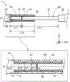
图1是示出了第一实施方式的导丝的整体结构的局部截面图。FIG. 1 is a partial sectional view showing the overall structure of a guide wire of a first embodiment.
图2是接置部周边(图1)的局部截面图。Fig. 2 is a partial cross-sectional view of the periphery of the contact portion (Fig. 1).
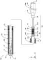
图3是对制造导丝的方法进行说明的图;其中,图3(A)图示的是插入工序,图3(B)图示的是配置工序,图3(C)图示的是涂覆工序,以及图3(D)图示的是移动工序。3 is a diagram illustrating a method of manufacturing a guide wire; wherein, FIG. 3(A) illustrates an insertion process, FIG. 3(B) illustrates an arrangement process, and FIG. 3(C) illustrates a coating process. Covering process, and Figure 3 (D) illustrates the moving process.
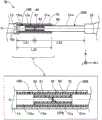
图4是示出了第二实施方式的导丝的整体结构的局部截面图。Fig. 4 is a partial sectional view showing the overall structure of the guide wire of the second embodiment.
图5是第二实施方式的接置部周边(图4)的局部截面图。Fig. 5 is a partial cross-sectional view of the periphery of the receiving portion ( Fig. 4 ) of the second embodiment.
图6是对制造第二实施方式的导丝的方法进行说明的图;其中,图6(A)图示的是插入工序,图6(B)图示的是配置工序,图6(C)图示的是第一涂覆工序,图6(D)图示的是第一移动工序及第二涂覆工序,图6(E)图示的是第二移动工序。6 is a diagram illustrating a method of manufacturing a guidewire according to a second embodiment; wherein, FIG. 6(A) illustrates an insertion process, FIG. 6(B) illustrates an arrangement process, and FIG. 6(C) The first coating step is shown in the drawing, the first moving step and the second coating step are shown in FIG. 6(D), and the second moving step is shown in FIG. 6(E).
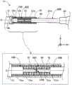
图7是示出了第三实施方式的导丝的整体结构的局部截面图。Fig. 7 is a partial sectional view showing the overall structure of the guide wire of the third embodiment.
图8是第三实施方式的接置部周边(图7)的局部截面图。Fig. 8 is a partial cross-sectional view of the periphery of the receiving portion ( Fig. 7 ) of the third embodiment.
图9是第四实施方式的导丝的接置部周边的局部截面图。Fig. 9 is a partial cross-sectional view around a receiving portion of a guide wire according to a fourth embodiment.
图10是示出了内侧包覆构件的概略结构的立体图。Fig. 10 is a perspective view showing a schematic structure of an inner covering member.
图11是第五实施方式的导丝的接置部周边的局部截面图。Fig. 11 is a partial cross-sectional view around a receiving portion of a guide wire according to a fifth embodiment.
图12是第六实施方式的导丝的接置部周边的局部截面图。Fig. 12 is a partial cross-sectional view around a receiving portion of a guide wire according to a sixth embodiment.
图13是第七实施方式的导丝的接置部周边的局部截面图。Fig. 13 is a partial cross-sectional view around a receiving portion of a guide wire according to a seventh embodiment.
图14是第八实施方式的导丝的接置部周边的局部截面图。Fig. 14 is a partial cross-sectional view around the receiving portion of the guide wire according to the eighth embodiment.
图15是第九实施方式的导丝的接置部周边的局部截面图。Fig. 15 is a partial cross-sectional view around a receiving portion of a guide wire according to a ninth embodiment.
图16是第十实施方式的导丝的接置部周边的局部截面图。Fig. 16 is a partial cross-sectional view around the receiving part of the guide wire according to the tenth embodiment.
图17是第十一实施方式的导丝的包覆构件附近的放大图。Fig. 17 is an enlarged view of the vicinity of the covering member of the guide wire according to the eleventh embodiment.
具体实施方式Detailed ways
<第一实施方式><First Embodiment>
图1是示出了第一实施方式的导丝1的整体结构的局部截面图。导丝1是例如在将导管插入血管中时使用的医疗器具,其包括第一芯轴10、线圈体20、第二芯轴30、前端侧固定部51、基端侧固定部52和包覆构件70。在图1中,经过导丝1的中心的轴,用轴线O(单点划线)来表示。在以后的示例中,经过第一芯轴10、线圈体20、第二芯轴30以及包覆构件70的各构件的中心的轴,均与轴线O一致。但是,这些经过各构件的中心的轴也可以分别与轴线O不同。FIG. 1 is a partial cross-sectional view showing the overall structure of a guide wire 1 of the first embodiment. The guide wire 1 is a medical instrument used, for example, when inserting a catheter into a blood vessel, and includes a
并且,在图1中,示出有彼此正交的XYZ轴。X轴对应于导丝1的轴向,Y轴对应于导丝1的高度方向,Z轴对应于导丝1的宽度方向。图1的左侧(-X轴方向)被称为导丝1和各结构构件的“前端侧”,而图1的右侧(+X轴方向)被称为导丝1和各结构构件的“基端侧”。另外,对于导丝1和各结构构件,位于前端侧的端部被称为“前端部”或简称为“前端”,位于基端侧的端部被称为“基端部”或简称为“基端”。在本实施方式中,前端侧相当于“远位侧”,基端侧相当于“近位侧”。这几点也适用于图1以后的、显示整体结构的附图。In addition, in FIG. 1 , XYZ axes orthogonal to each other are shown. The X axis corresponds to the axial direction of the guide wire 1 , the Y axis corresponds to the height direction of the guide wire 1 , and the Z axis corresponds to the width direction of the guide wire 1 . The left side of Figure 1 (-X axis direction) is referred to as the "front end side" of the guide wire 1 and each structural member, while the right side of Figure 1 (+X axis direction) is referred to as the "front end side" of the guide wire 1 and each structural member. "Basal side". In addition, for the guide wire 1 and each structural member, the end located on the front end side is referred to as "tip end" or simply "tip end", and the end located on the base end side is called "base end" or simply "tip end". basal end". In the present embodiment, the distal side corresponds to the "distal side", and the proximal side corresponds to the "proximal side". These points also apply to the drawings following FIG. 1 , which show the overall structure.
第一芯轴10是中央为粗径、两端侧(前端侧、基端侧)为细径的细长状构件。第一芯轴10由超弹性材料如NiTi(镍钛)合金、或NiTi与其他金属的合金制成。第一芯轴10从前端侧朝向基端侧,依次具有前端细径部11、前端缩径部12、第一粗径部13以及第一细径部15。各部的外径和长度可以任意设定。The
前端细径部11,配置在第一芯轴10的前端部。前端细径部11为第一芯轴10的外径最小的部分,并且为具有恒定外径的大致圆柱形状。前端缩径部12,配置在前端细径部11与第一粗径部13之间。前端缩径部12,为从基端侧朝向前端侧外径缩径的大致圆锥台形状。第一粗径部13,配置在前端缩径部12与第一细径部15之间。第一粗径部13为第一芯轴10的外径最大的部分,并且为具有恒定外径的大致圆柱形状。第一细径部15,配置在第一芯轴10的基端部。第一细径部15是具有比第一粗径部13小、且比前端细径部11大的恒定外径的大致圆柱形状。The small-
第二芯轴30是,基端侧为粗径且前端侧为细径的、前端变细的细长状构件。第二芯轴30由比第一芯轴10具有更高刚性的材料,例如SUS304、SUS316等不锈钢合金制成。第二芯轴30从前端侧朝向基端侧,依次具有第二细径部31、第二粗径部33、基端缩径部34、以及基端粗径部35。各部的外径和长度可以任意设定。The
第二细径部31,配置在第二芯轴30的前端部。第二细径部31为第二芯轴30的外径最小的部分,并且为具有与第一芯轴10的第一细径部15大致相同的恒定外径的大致圆柱形状。第二粗径部33,配置在第二细径部31与基端缩径部34之间。第二粗径部33是具有比基端粗径部35小、且比第二细径部31大的恒定外径的大致圆柱形状。基端缩径部34,配置在第二粗径部33与基端粗径部35之间。基端缩径部34,为从基端侧朝向前端侧外径缩径的大致圆锥台形状。基端粗径部35配置在第二芯轴30的基端部。基端粗径部35为第二芯轴30的外径最大的部分,并且为具有恒定外径的大致圆柱形状。The second
第一芯轴10中,前端细径部11、前端缩径部12及第一粗径部13的前端侧,被后述的线圈体20覆盖。另一方面,第一芯轴10的第一粗径部13的基端侧、第一细径部15和第二芯轴30的各部未被线圈体20覆盖,而是从线圈体20露出。第二芯轴30的基端粗径部35,在手术者把持导丝1时被使用。In the
线圈体20是将线材21螺旋状地卷绕在第一芯轴10上而形成的大致圆筒形状。形成线圈体20的线材21可以是由一根线材构成的单线,也可以是捻合多根线材而成的绞线。在线材21为单线的情况下,线圈体20构成为单线圈,在线材21为绞线的情况下,线圈体20构成为中空绞线线圈。此外,也可将单线圈与中空绞线线圈组合而构成线圈体20。线材21的线径和线圈体20的线圈平均直径(线圈体20的外径和内径的平均直径)可以任意设定。The
线材21可以由例如SUS304、SUS316等不锈钢合金、NiTi合金等超弹性合金、琴钢丝、镍-铬系合金、钴合金等放射线透过性合金;金、铂、钨或包括这些元素的合金(例如,铂-镍合金)等放射线不透过性合金制成。另外,线材21还可以由除上述以外的公知材料制成。The
前端侧固定部51配置在导丝1的前端部,并将第一芯轴10的前端细径部11的前端部、以及线圈体20的前端部保持为一体。前端侧固定部51可以由任意的接合剂,例如银焊料、金焊料、锌、Sn-Ag合金、Au-Sn合金等金属焊料、或环氧树脂系粘合剂等粘合剂而制成。基端侧固定部52配置在第一芯轴10的第一粗径部13的靠近基端侧的一部分上,并将第一芯轴10、以及线圈体20的基端部保持为一体。基端侧固定部52与前端侧固定部51同样,可以由任意的接合剂制成。基端侧固定部52和前端侧固定部51可以使用相同的接合剂,也可以使用不同的接合剂。The distal
中间固定部61在线圈体20的轴线O方向的中间部附近,将线圈体20和第一芯轴10保持为一体。中间固定部61与前端侧固定部51同样,可以由任意的接合剂制成。中间固定部61和前端侧固定部51可以使用相同的接合剂,也可以使用不同的接合剂。在图1中,示例了1个中间固定部61,但也可以在导丝1上设置多个中间固定部61。The
图2是接置部周边1pa(图1)的局部截面图。在图2中,上部图示了第一及第二芯轴10、30的接置部周边的局部截面图,下部图示了包覆构件70附近的放大图。图2所示的X、Y、Z轴,分别对应于图1的X、Y、Z轴。这一点对于图2以后的标注了X、Y、Z轴的图也相同。Fig. 2 is a partial sectional view of the periphery 1pa (Fig. 1) of the contact portion. In FIG. 2 , the upper part shows a partial cross-sectional view around the contact portion of the first and
第一及第二芯轴10、30,在使第一芯轴10的中心轴与第二芯轴30的中心轴彼此一致的状态下,对向而配置(对向配置)。在图示的示例中,第一及第二芯轴10、30的各中心轴与轴线O一致。但是,第一及第二芯轴10、30也可以在与轴线O不同的YZ平面上的位置处,彼此的中心轴一致。而且,第一及第二芯轴10、30的中心轴也可以互相不同。此后,将第一及第二芯轴10、30相对的部分称为“接置部CP”。在图示的示例中,接置部CP是,第一芯轴10的第一细径部15的基端部与第二芯轴30的第二细径部31的前端部的相邻部分。The first and
在本实施方式中,第一及第二芯轴10、30在接置部CP处接合。接合例如可以通过对相邻配置在接置部CP的第一芯轴10的第一细径部15与第二芯轴30的第二细径部31之间的间隙使用接合剂81填埋固定来实施。此时,可以在第一细径部15与第二细径部31之间的整个间隙(换言之,第一细径部15的基端侧的端面和第二细径部31的前端侧的端面的整个面)配置有接合剂81,也可以仅在间隙的一部分配置有接合剂81,而其他部分为空隙。接合剂81,例如可以使用银焊料、金焊料、锌、Sn-Ag合金、Au-Sn合金等金属焊料、或环氧树脂系粘合剂等粘合剂。此外,在接置部CP处的接合也可以通过第一及第二芯轴10、30的焊接来实施。In the present embodiment, the first and
另外,第一及第二芯轴10、30也可以不在接置部CP处接合。在这种情况下,在接置部CP处,第一细径部15的基端侧的端面与第二细径部31的前端侧的端面可以接触,第一细径部15的基端侧的端面与第二细径部31的前端侧的端面也可以隔着间隙相邻。In addition, the first and
包覆构件70是,形成为具有恒定外径的管形状(大致圆筒形状)的金属制管状构件。包覆构件70优选形成为弯曲刚性比第二芯轴30低、并且具有与第一芯轴10相同程度的弹性模量的结构。包覆构件70与第一芯轴10相同,可以由超弹性材料、例如NiTi合金或NiTi与其他金属的合金制成。包覆构件70可以由与第一芯轴10相同的材料制成,也可以由不同的材料制成。The covering
包覆构件70被这样配置,即包覆构件70的一端(在图示的示例中为前端部)位于第一芯轴10的第一粗径部13与第一细径部15的边界附近10b。而且,包覆构件70分别覆盖第一及第二芯轴10、30的接置部CP、与接置部CP相邻的第一芯轴10的一部分(在图示的示例中,比第一细径部15的基端部更靠近前端侧)、以及第二芯轴30的一部分(在图示的示例中,比第二细径部31的前端部更靠近基端侧的一部分)。换言之,在接置部CP处接合的第一及第二芯轴10、30,以贯通包覆构件70的内腔的方式沿轴线O方向延伸。The covering
接合层90配置在包覆构件70的内侧,将包覆构件70与第一及第二芯轴10、30(第一细径部15、第二细径部31)接合,并保持为一体。在图示的示例中,接合层90形成在包覆构件70与被包覆构件70覆盖的第一及第二芯轴10、30之间的整个间隙中,将第一及第二细径部15、31的接置部CP、与接置部CP相邻的第一芯轴10的第一细径部15和与接置部CP相邻的第二芯轴30的第二细径部31接合。另外,接合层90可以不形成在包覆构件70与第一及第二芯轴10、30之间的整个间隙,而仅形成在一部分上。在形成于一部分上的情况下,可以在包覆构件70与第一及第二芯轴10、30之间留有空隙。接合层90与前端侧固定部51同样,可以由任意的接合剂制成。接合层90和前端侧固定部51可以使用相同的接合剂,也可以使用不同的接合剂。The
如图2上部所示,在本实施方式中,第一芯轴10的第一细径部15在轴线O方向上的长度L11,小于第二芯轴30的第二细径部31在轴线O方向上的长度L12(L11<L12)。而且,包覆构件70在轴线O方向上的长度L13,小于第一细径部15在轴线O方向上的长度L11和第二细径部31在轴线O方向上的长度L12之和(L13<L11+L12)。进一步地,包覆构件70在轴线O方向上的长度L13,大于第一及第二细径部15、31中在轴线O方向上的长度较短的一方(即,第一细径部15的长度L11)(L13>L11)。另外,长度L11、12、13只要满足上述关系,则可以任意设定。As shown in the upper part of FIG. 2 , in this embodiment, the length L11 of the first
如图2下部所示,在本实施方式中,包覆构件70的内径D71大于第一芯轴10的第一细径部15的直径D11(D71>D11)。而且,包覆构件70的外径D72,与第一芯轴10的第一粗径部13的直径D12大致相同(D72=D12)。另外,内径D71、外径D72、直径D11、12只要满足上述关系,则可以任意设定。As shown in the lower part of FIG. 2 , in this embodiment, the inner diameter D71 of the covering
图3是对制造导丝1的方法进行说明的图。图3(A)图示的是插入工序。同样地,图3(B)图示的是配置工序,图3(C)图示的是涂覆工序,图3(D)图示的是移动工序。首先,在准备工序中,分别预先准备具有第一粗径部13和第一细径部15的第一芯轴10、具有第二粗径部33和第二细径部31的第二芯轴30、以及具有上述长度L13的管形状的包覆构件70。FIG. 3 is a diagram illustrating a method of manufacturing the guide wire 1 . FIG. 3(A) illustrates the insertion process. Similarly, FIG. 3(B) shows the disposing process, FIG. 3(C) shows the coating process, and FIG. 3(D) shows the moving process. First, in the preparation step, the
接着,如图3(A)的空心箭头所示,从第二芯轴30的第二细径部31的一侧插入包覆构件70(插入工序)。在图3(B)的示例中,使包覆构件70移动(滑动),直至包覆构件70的基端部位于第二芯轴30的第二细径部31与第二粗径部33的边界附近30b。接着,如图3(B)所示,相对于包覆构件70插入状态下的第二芯轴30的第二细径部31,以对向状态配置第一芯轴10的第一细径部15(配置工序)。然后,通过向第一细径部15和第二细径部31的对向部分(接置部CP)配置接合剂81,将第一及第二芯轴10、30接合。Next, as shown by the hollow arrow in FIG. 3(A), the covering
接着,如图3(C)所示,向接置部CP的表面、以及与接置部CP相邻且从包覆构件70露出的第一及第二细径部15、31的各表面(在图示的示例中,第一细径部15的表面和第二细径部31的前端侧的表面),涂覆用于形成接合层90的接合剂(涂覆工序)。在图示的示例中,向从包覆构件70露出的第一及第二细径部15、31的整个表面涂覆接合剂,但是接合剂的涂覆也可以只是第一及第二细径部15、31的表面的一部分。接着,如图3(D)的空白箭头所示,使包覆构件70向涂覆有形成接合层90的接合剂的位置移动(滑动)(移动工序)。在图示的示例中,包覆构件70移动至前端部位于第一芯轴10的第一粗径部13与第一细径部15的边界附近10b。Next, as shown in FIG. In the illustrated example, the surface of the first small-
如上所述,根据本实施方式的导丝1,包覆构件70在轴线O方向上的长度L13,小于第一及第二细径部15、31在轴线O方向上的各长度L11、L12之和,并且,大于第一及第二细径部15、31中在轴线方向上的长度较短的一方(在上述示例中,第一细径部15的长度L11),且小于在轴线O方向上的长度较长的另一方(在上述示例中,第二细径部31的长度L12)(图2上部)。因此,如图3说明所示,制造本实施方式的导丝1时,在第一及第二细径部15、31中在轴线O方向上的长度较长的另一方(在上述示例中,第二细径部31)被插入包覆构件70的状态(图3(A))下,将第一及第二细径部15、31对向配置(图3(B)),在第一及第二细径部15、31的表面涂覆接合剂(图3(C))后,能够使包覆构件70向第一及第二细径部15、31的表面的所期望的位置移动(图3(D))。其结果,通过使包覆构件70滑动至作为第一及第二细径部15、31中较短的一方(在上述示例中,第一细径部15)的粗径部的端部(换言之,接置部CP相反侧的端部),包覆构件70可以容易地覆盖第一及第二细径部15、31的接置部CP。As described above, according to the guide wire 1 of the present embodiment, the length L13 of the covering
如图3(D)所示,在涂覆有接合剂的状态下的第一及第二细径部15、31的表面,通过使包覆构件70移动,涂覆于第一及第二细径部15、31的表面的多余的接合剂被包覆构件70的端部(端面)挤出并排出。因此,如图3所示地制造导丝1,则无需在包覆构件70设置成为应力集中的要因的孔,从而能够抑制因在包覆构件70的内侧填充有多余的接合剂(固定材料)所导致的包覆构件70的内部压力的上升。其结果,根据本实施方式,在包括被包覆构件70覆盖的第一及第二芯轴10、30的导丝1中,能够抑制包覆构件70的破损。此外,根据本实施方式,由于不需要在包覆构件70上形成孔的工序,因此能够减少导丝1的制造工时。As shown in FIG. 3(D), the surfaces of the first and second
此外,根据本实施方式的导丝1,第一及第二细径部15、31中较短的一方(在上述示例中,第一细径部15)配置在导丝1的前端侧,而且,构成前端侧的第一芯轴10的材质与构成基端侧的第二芯轴30的材质相比,为弯曲刚性小的材质。因此,能够提高导丝1的前端侧的柔软性。再者,位于导丝1的前端侧的第一芯轴10由超弹性合金如NiTi合金等构成,因此导丝1的前端侧难以塑性变形,其结果,能够抑制导丝1的前端侧的破损。In addition, according to the guide wire 1 of the present embodiment, the shorter one of the first and second small-
此外,根据本实施方式的导丝1,包覆构件70在轴线O方向上的长度L13,大于第一细径部15在轴线O方向上的长度L11(图2上部)。因此,在制造导丝1时,在第一及第二细径部15、31的表面上涂覆接合剂后,如图3(D)所示,通过使包覆构件70移动至第一细径部15的接置部CP相反侧的端部(即前端部),能够简单地得到接置部CP及其附近被包覆构件70覆盖的结构。Furthermore, according to the guide wire 1 of the present embodiment, the length L13 of the covering
并且,根据本实施方式的导丝1,接合层90在包覆构件70的内侧,将接置部CP、第一芯轴10(第一细径部15)和第二芯轴30(第二细径部31)接合(图2上部)。因此,可以将近手部分(图1:基端粗径部35)处的对导丝1的旋转操作或推入操作等操作,传递到导丝1的前端侧,并可以提高导丝1的扭矩传递性或推入性(操作性)。而且,如上述实施方式所示,即使在因第一及第二芯轴10、30的材料不同等而使第一及第二芯轴10、30的刚性各不相同时,也能够通过包覆构件70缓和第一及第二芯轴10、30的刚性差异。因此,能够抑制第一及第二芯轴10、30在接置部CP附近的变形(弯折、扭曲、压溃),并且能够提高导丝1的抗扭结性。Furthermore, according to the guide wire 1 of the present embodiment, the
并且,根据本实施方式的导丝1,通过将包覆构件70形成为超弹性材料的管形状,能够进一步增强由包覆构件70带来的刚性差异缓和效果,并且能够进一步提高导丝1的抗扭结性。此外,通过由超弹性材料制成第一芯轴10,能够提高对弯曲的柔软性和复原性,通过由比第一芯轴10具有更高刚性的材料制成第二芯轴30,能够提高导丝1的扭矩传递性和推入性(操作性)。Furthermore, according to the guide wire 1 of the present embodiment, by forming the covering
进一步地,根据本实施方式的导丝1,包覆构件70的外径D72,与第一芯轴10的第一粗径部13的直径D12大致相同(图2下部)。因此,能够将第一芯轴10与包覆构件70的连接部分的表面形状设置为没有凹凸的平坦形状,从而在通过导丝1推进球囊导管等医疗器械时抑制医疗器械的卡挂,其结果,能够抑制医疗器械的破损。Further, according to the guide wire 1 of the present embodiment, the outer diameter D72 of the covering
<第二实施方式><Second Embodiment>
图4是示出了第二实施方式的导丝1A的整体结构的局部截面图。图5是第二实施方式的接置部周边1pa(图4)的局部截面图。图5中的上部、下部的结构与图2相同。在第二实施方式的导丝1A中,主要是轴线O方向上的包覆构件70A的配置与第一实施方式不同。FIG. 4 is a partial cross-sectional view showing the overall structure of a
包覆构件70A配置成,位于在接置部CPA处接合的第一芯轴10A的第一细径部15A与第二芯轴30A的第二细径部31A的中央附近。换言之,包覆构件70A的前端部从第一芯轴10A的第一粗径部13与第一细径部15A的边界附近,沿轴线O方向隔开距离而配置。并且,包覆构件70A的基端部从第二芯轴30A的第二粗径部33与第二细径部31A的边界附近,沿轴线O方向隔开距离而配置。包覆构件70A与第一实施方式相同,分别覆盖第一及第二芯轴10A、30A的接置部CPA、与接置部CPA相邻的第一芯轴10A的一部分(在图示的示例中,比第一细径部15A的基端部更靠近前端侧的一部分)、以及第二芯轴30A的一部分(在图示的示例中,比第二细径部31A的前端部更靠近基端侧的一部分)。The covering
而且,导丝1A设有两处接合层91及接合层92以取代第一实施方式的接合层90。接合层91在包覆构件70A的内侧,将包覆构件70A的前端侧的一部分与第一芯轴10A(第一细径部15A)接合。接合层92在包覆构件70A的内侧,将包覆构件70A的基端侧的一部分与第二芯轴30A(第二细径部31A)接合。在图示的示例中,接合层91和接合层92仅形成在轴线O方向上的、包覆构件70A的两端部分上,并未形成在包覆构件70A的中央部附近。即,在包覆构件70A的中央部附近,在包覆构件70A的内侧面与跟接置部CPA相邻的第一及第二细径部15A、31A的外侧面之间,存在空隙。接合层91和接合层92,与前端侧固定部51相同,可以由任意的接合剂制成。接合层91及接合层92和前端侧固定部51可以使用相同的接合剂,也可以使用不同的接合剂。Furthermore, the
如图5上部所示,第二实施方式也与第一实施方式相同,第一芯轴10A的第一细径部15A在轴线O方向上的长度L21,小于第二芯轴30A的第二细径部31A在轴线O方向上的长度L22(L21<L22)。而且,包覆构件70A在轴线O方向上的长度L23,小于第一细径部15A在轴线O方向上的长度L21和第二细径部31A在轴线O方向上的长度L22之和(L23<L21+L22)。进一步地,包覆构件70A在轴线O方向上的长度L23,大于第一及第二细径部15A、31A中在轴线O方向上的长度较短的一方(第一细径部15A的长度L21)(L23>L21)。长度L21、22、23只要满足上述关系,则可以任意设定。此外,关于包覆构件70A的内径D71及外径D72、第一细径部15A的直径D11、第一粗径部13的直径D12的大小关系,也与第一实施方式相同。As shown in the upper part of FIG. 5 , the second embodiment is also the same as the first embodiment, and the length L21 of the first
图6是对制造第二实施方式的导丝1A的方法进行说明的图。图6(A)图示的是插入工序。同样地,图6(B)图示的是配置工序,图6(C)图示的是第一涂覆工序,图6(D)图示的是第一移动工序及第二涂覆工序,图6(E)图示的是第二移动工序。关于准备工序、插入工序、配置工序,与图3中描述的第一实施方式相同。FIG. 6 is a diagram illustrating a method of manufacturing the
配置工序结束后,如图6(C)所示,在从包覆构件70A露出的第一细径部15A的表面上,涂覆用于形成接合层91的接合剂(第一涂覆工序)。图示的示例中,是在从包覆构件70A露出的第一细径部15A的整个表面上涂覆接合剂,但是接合剂的涂覆也可以只是第一细径部15A的表面的一部分。接着,如图6(D)的空白箭头所示,使包覆构件70A向涂覆有用于形成接合层91的接合剂的位置移动(滑动)(第一移动工序)。在图示的示例中,使包覆构件70A移动,直至其前端部位于第一粗径部13与第一细径部15A的边界附近10b。After the arrangement step is completed, as shown in FIG. 6(C), a bonding agent for forming the
接着,如图6(D)所示,在从移动后的包覆构件70A露出的第二细径部31A的表面上,涂覆用于形成接合层92的接合剂(第二涂覆工序)。在图示的示例中,是在从包覆构件70A露出的第二细径部31A的整个表面上涂覆接合剂,但是接合剂的涂覆也可以只是第二细径部31A的表面的一部分。最后,如图6(E)的空白箭头所示,将包覆构件70A移动至第一细径部15A与第二细径部31A的中央附近(第二移动工序)。Next, as shown in FIG. 6(D), a bonding agent for forming the
如此,包覆构件70A可以从第一及第二芯轴10A、30A的粗径部及细径部的边界附近,沿轴线O方向隔开距离而配置,包覆构件70A的配置也可以不必一定是第一及第二细径部15A、31A的中央附近。并且,包覆构件70A也可以在内侧面与第一及第二芯轴10A、30A的外侧面(表面)之间设置空隙而接合。In this way, the covering
即使在这样的第二实施方式的导丝1A中,也可以获得与第一实施方式相同的效果。即,包括被包覆构件70A覆盖的第一及第二芯轴10A、30A的导丝1A,可抑制包覆构件70A的破损,并且不需要在包覆构件70A上形成孔的工序,因此能够减少导丝1A的制造工时。并且,根据第二实施方式的导丝1A,由于两处接合层91和接合层92在包覆构件70A的内侧接合包覆构件70A的两端部分、第一及第二细径部15A、31A,因此能够将近手部分的对导丝1A的操作向前端侧传递,从而能够提高导丝1A的扭矩传递性和推入性(操作性)。并且,即使在第一及第二芯轴10A、30A的刚性各不相同的情况下,也能够通过包覆构件70A来缓和该刚性差异,因此能够抑制第一及第二芯轴10A、30A在接置部CPA附近的变形,从而能够提高导丝1A的抗扭结性。Even in such a
<第三实施方式><Third Embodiment>
图7是示出了第三实施方式的导丝1B的整体结构的局部截面图。图8是第三实施方式的接置部周边1pa(图7)的局部截面图。图8中的上部、下部的结构与图2相同。在第三实施方式的导丝1B中,第一及第二芯轴10B、30B在接置部周边1pa的结构,与第一实施方式不同,并且在包覆构件70的内侧还设有内侧包覆构件40。Fig. 7 is a partial sectional view showing the overall structure of the
第一芯轴10B的第一细径部15,包括第一端部侧细径部15e及第一中间细径部15m。第一端部侧细径部15e设置在第一芯轴10B的基端部侧,为具有比第一中间细径部15m细的恒定外径的大致圆柱形状。第一中间细径部15m,设置在第一端部侧细径部15e与第一粗径部13之间,是具有比第一端部侧细径部15e粗且比第一粗径部13细的恒定外径的大致圆柱形状。第二芯轴30B的第二细径部31,包括第二端部侧细径部31e及第二中间细径部31m。第二端部侧细径部31e,设置在第二芯轴30B的前端部侧,为具有比第二中间细径部31m细的恒定外径的大致圆柱形状。第二中间细径部31m,设置在第二端部侧细径部31e与第二粗径部33之间,是具有比第二端部侧细径部31e粗且比第二粗径部33细的恒定外径的大致圆柱形状。The first small-
如图8下部所示,在接置部CPB处,第一芯轴10B的第一端部侧细径部15e的基端侧的端面与第二芯轴30B的第二端部侧细径部31e的前端侧的端面相邻配置。在接置部CPB处,接合有第一及第二芯轴10B、30B。该接合除了与第一实施方式相同能够采用各种方式之外,还可以省略接合。As shown in the lower part of FIG. 8 , at the contact portion CPB, the end surface on the base end side of the first end side
内侧包覆构件40是,形成为具有恒定外径的管形状(大致圆筒形状)的金属制管状构件。本实施方式的内侧包覆构件40为弯曲刚性比第二芯轴30B低、且具有与第一芯轴10B相同程度的弹性模量的结构。内侧包覆构件40与包覆构件70相同,可以由超弹性材料如NiTi合金、或NiTi与其他金属的合金制成。内侧包覆构件40可以由与包覆构件70相同的材料制成,也可以由不同的材料制成。The
内侧包覆构件40在包覆构件70的内侧,配置成分别覆盖接置部CPB、与接置部CPB相邻的第一芯轴10B的一部分(在图示的示例中,为第一端部侧细径部15e)、以及与接置部CPB相邻的第二芯轴30B的一部分(在图示的示例中,为第二端部侧细径部31e)。在本实施方式中,内侧包覆构件40在轴线O方向上的长度,大致等于第一端部侧细径部15e在轴线O方向上的长度和第二端部细径部31e在轴线O方向上的长度之和。另外,内侧包覆构件40的长度可以任意设定。The
内侧包覆构件40通过配置在内侧包覆构件40内侧的接合层93,与第一及第二芯轴10B、30B(第一端部侧细径部15e、第二端部侧细径部31e)接合。在图示的示例中,接合层93形成在,内侧包覆构件40与被内侧包覆构件40覆盖的第一及第二端部侧细径部15e、31e之间的间隙中、除了第一端部侧细径部15e的前端部和第二端部侧细径部31e的基端部以外的大致整体上。通过这样的接合层93,将第一及第二端部侧细径部15e、31e的接置部CPB、与跟接置部CPB相邻的第一及第二端部侧细径部15e、31e接合。接合层93与前端侧固定部51相同,可以由任意的接合剂形成。接合层93和前端侧固定部51可以使用相同的接合剂,也可以使用不同的接合剂。The
如图8上部所示,第三实施方式中,也与第一实施方式相同,第一芯轴10B的第一细径部15(即,第一端部侧细径部15e及第一中间细径部15m)在轴线O方向上的长度L31,小于第二芯轴30B的第二细径部31(即,第二端部侧细径部31e及第二中间细径部31m)在轴线O方向上的长度L32(L31<L32)。此外,关于包覆构件70在轴线O方向上的长度L33与长度L31、32的关系,也与第一实施方式相同(L33<L31+L32、L33>L31)。长度L31、32、33只要满足上述关系,则可以任意设定。As shown in the upper part of FIG. 8 , in the third embodiment, as in the first embodiment, the first small-
这样,在包覆构件70的内侧还可以设有内侧包覆构件40。而且,第一芯轴10B的第一细径部15和第二芯轴30B的第二细径部31可以由两个以上的多个细径部构成。第三实施方式的导丝1B,可以用与图3中描述的第一实施方式相同的方法制造。In this way, the
即使在这种第三实施方式的导丝1B中,也可以获得与第一实施方式相同的效果。进一步地,根据第三实施方式的导丝1B,在包覆构件70的内侧配置有,覆盖接置部CPB、以及与接置部CPB相邻的第一及第二端部侧细径部15e、31e的内侧包覆构件40。因此,即使在第一及第二芯轴10B、30B的刚性各不相同的情况下,也能够通过内侧包覆构件40来缓和第一及第二芯轴10B、30B的刚性差异。而且,即使在第一芯轴10B、第二芯轴30B和包覆构件70的刚性各不相同的情况下,也能够通过内侧包覆构件40来缓和它们的刚性差异。因此,能够抑制第一及第二芯轴10B、30B在接置部CPB附近的变形、或第一及第二芯轴10B、30B在内侧包覆构件40附近的变形,并且能够进一步提高导丝1B的抗扭结性。Even in the
进一步地,在使细长的导丝1B在基端侧以轴线O为中心旋转的情况下,如果接合后的包覆构件70、和第一及第二芯轴10B、30B各自的中心轴由于加工误差而从轴线O偏移,则在把持导丝1B的第二芯轴30B并以轴线O为旋转轴旋转时,第一芯轴10B的旋转会产生紊乱。虽然期望通过组装尽量减小这样的旋转紊乱,但组装需要耗费时间。Further, when the
在第三实施方式的导丝中,通过使内侧包覆构件40的外径与第一及第二芯轴10B、30B各自的外径一致,从而能够抑制第一芯轴10B的第一端部侧细径部15e和第二芯轴30B的第二端部侧细径部31e的加工精度对旋转紊乱的波及。而且,通过内侧包覆构件40的外径与第一及第二芯轴10B、30B呈一体的结构,能够抑制包覆构件70的内面加工精度对旋转紊乱的波及。因此,即使在包覆构件70的内面、第一及第二芯轴10B、30B的第一端部及第二端部侧细径部15e、31e的外面产生加工误差时,也能够抑制导丝1B的第一芯轴10B的旋转紊乱。In the guide wire of the third embodiment, by making the outer diameter of the
<第四实施方式><Fourth Embodiment>
图9是第四实施方式的导丝1C的接置部周边的局部截面图。图9中的上部、下部的结构与图2相同。第四实施方式的导丝1C,在第三实施方式的结构基础上,设有与第三实施方式的结构不同的内侧包覆构件40C。FIG. 9 is a partial cross-sectional view around the receiving portion of the
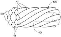
图10是示出了内侧包覆构件40C的概略结构的立体图。内侧包覆构件40C是多股卷绕8根线材41而成的多股线圈,是具有恒定外径的大致圆筒形状。内侧包覆构件40C优选弯曲刚性低于第二芯轴30B的结构。内侧包覆构件40C可以通过,例如将8根线材41以彼此接触的方式紧密地捻合在芯骨上之后、使用公知的热处理方法去除残余应力、取出芯骨,而形成。以这种方式形成的内侧包覆构件40C,如图10所示,为具有内腔40h(图10:虚线)的多股线圈。线材41的材料,可以与线材21的材料相同,也可以不同。另外,内侧包覆构件40C可以采用任意形式,例如,构成内侧包覆构件40C的线材的数量不限于8根,可以任意设定。内侧包覆构件40C不限于多股线圈,也可以是使用一根线材形成的单股线圈,还可以由具有疏水性的树脂材料、具有亲水性的树脂材料、或它们的混合物涂覆而成。FIG. 10 is a perspective view showing a schematic structure of the
如此,内侧包覆构件40C可以采用各种结构。即使在这样的第四实施方式的导丝1C中,也可以获得与第一及第三实施方式相同的效果。此外,在第四实施方式的导丝1C中,在包覆构件70的内侧,通过为形成接合层90而配置的接合剂进入内侧包覆构件40C的各线材的间隙或内侧包覆构件40C的内侧,能够使内侧包覆构件40C与第一及第二芯轴10B、30B接合。In this way, various structures can be adopted for the
在使用多股线圈作为内侧包覆构件40C的情况下,由于比管状的内侧包覆构件对弯曲更柔软,因此即使在接置部CPB被施加弯曲应力时,也能够使该应力更容易分散到第一及第二芯轴10B、30B。In the case of using a multi-strand coil as the
<第五实施方式><Fifth Embodiment>
图11是第五实施方式的导丝1D的接置部周边的局部截面图。图11中的上部、下部的结构与图2相同。第五实施方式的导丝1D,在第四实施方式的结构基础上,设有将内侧包覆构件40C固定于第一及第二芯轴10B、30B的内侧固定部95。内侧固定部95配置成覆盖内侧包覆构件40C,并将第一芯轴10B的第一端部侧细径部15e、第二芯轴30B的第二端部侧细径部31e以及内侧包覆构件40C固定为一体。内侧固定部95与前端侧固定部51相同,可以由任意的接合剂形成。内侧固定部95和前端侧固定部51可以使用相同的接合剂,也可以使用不同的接合剂。Fig. 11 is a partial cross-sectional view around the receiving part of the
如此,内侧包覆构件40C和包覆构件70,也可以分别单独地固定于第一及第二芯轴10B、30B。即使在这样的第五实施方式的导丝1D中,也可以获得与第一及第三实施方式相同的效果。并且能够获得与应力分散有关的与第四实施方式相同的效果。此外,根据第五实施方式的导丝1D,在导丝1D的制造中,可以独立实施将内侧包覆构件40C固定于第一及第二芯轴10B、30B(形成内侧固定部95)的工序、以及将包覆构件70C固定于第一及第二芯轴10B、30B(形成接合层90)的工序。In this manner, the
<第六实施方式><Sixth Embodiment>
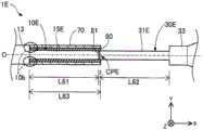
图12是第六实施方式的导丝1E的接置部周边的局部截面图。在第六实施方式的导丝1E中,第一芯轴10E的第一细径部15E在轴线O方向上的长度L61被设置成,与第二芯轴30E的第二细径部31E在轴线O方向上的长度L62相等的长度(L61=L62)。这里,包含误差范围在内的大致相同的长度也包含在“相等的长度”中。此外,即使在第六实施方式中,也与第一实施方式相同,包覆构件70在轴线O方向上的长度L63,小于第一细径部15E在轴线O方向上的长度L61和第二细径部31E在轴线O方向上的长度L62之和(L63<L61+L62)。进一步地,包覆构件70在轴线O方向上的长度L63大于第一细径部15E在轴线O方向上的长度L61(L63>L61),大于第二细径部31E在轴线O方向上的长度L62(L63>L62)。而且,长度L61、62、63只要满足上述关系,则可以任意设定。Fig. 12 is a partial cross-sectional view around the receiving part of the
如此,第一及第二芯轴10E、30E的第一及第二细径部15E、31E在轴线O方向上的长度可以大致相同。即使在这种第六实施方式中,也可以获得与第一实施方式相同的效果。而且,根据第六实施方式的导丝1E,由于第一及第二细径部15E、31E在轴线O方向上的长度相等,因此第一及第二芯轴10E、30E更容易制造。In this way, the lengths of the first and second small-
<第七实施方式><Seventh Embodiment>
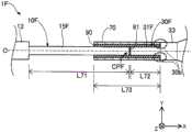
图13是第七实施方式的导丝1F的接置部周边的局部截面图。在第七实施方式的导丝1F中,第一及第二芯轴10F、30F的第一及第二细径部15F、31F在轴线O方向上的各长度的关系,与第一实施方式相反。即,第一芯轴10F的第一细径部15F在轴线O方向上的长度L71,大于第二芯轴30F的第二细径部31F在轴线O方向上的长度L72(L71>L72)。而且,包覆构件70在轴线O方向上的长度L73,小于长度L71与L72之和(L73<L71+L72),大于第一及第二细径部15F、31F中在轴线O方向上的长度较短的一方(即,第二细径部31F的长度L72)(L73>L72)。而且长度L71、72、73只要满足上述关系则可以任意设定。Fig. 13 is a partial cross-sectional view around the receiving part of the
此外,在第七实施方式中,包覆构件70配置成,包覆构件70的一端(在图示的示例中为基端部)位于第二芯轴30F的第二细径部31F与第二粗径部33的边界附近30b。包覆构件70与第一实施方式相同,覆盖第一及第二芯轴10F、30F的接置部CPF,以及与接置部CPF相邻的第一及第二芯轴10F、30F的各一部分。第七实施方式的导丝1F,只需在图3说明的制造方法中,将“第一芯轴10的第一细径部15”替换为“第二芯轴30F的第二细径部31F”、将“第二芯轴30的第二细径部31”替换为“第一芯轴10F的第一细径部15F”即可。In addition, in the seventh embodiment, the covering
如此,第一及第二芯轴10F、30F的第一及第二细径部15F、31F在轴线O方向上的各长度,可以任意设定,还可以使位于导丝1F的基端侧的第二芯轴30F侧缩短。即使在这样的第七实施方式中,也可以获得与第一实施方式相同的效果。In this way, the respective lengths of the first and second small-
<第八实施方式><Eighth Embodiment>
图14是第八实施方式的导丝1G的接置部周边的局部截面图。第八实施方式的导丝1G中,第一及第二芯轴10G、30G分别设有第一及第二中间部14、32。第一中间部14在第一芯轴10G中,形成在第一粗径部13与第一细径部15之间。第一中间部14为从基端侧朝向前端侧外径扩径的大致圆锥台形状。第二中间部32在第二芯轴30G中,形成在第二粗径部33与第二细径部31之间。第二中间部32为从基端侧朝向前端侧外径缩径的大致圆锥台形状。FIG. 14 is a partial cross-sectional view around the receiving portion of the
在设有第一及第二中间部14、32的结构中,第一实施方式中所说的“边界附近10b、30b”,包含第一及第二中间部14、32。包覆构件70可以配置成,使得包覆构件70的前端部如图所示一般位于第一中间部14的基端部。而且,包覆构件70可以配置成使得包覆构件70的前端部位于第一中间部14的轴线O方向的大致中央部分,也可以配置成位于第一中间部14的前端部。如此,第一及第二芯轴10G、30G的结构可以任意变化。即使在第八实施方式的导丝1G中,也可以获得与第一实施方式相同的效果。In the structure provided with the first and second
<第九实施方式><Ninth Embodiment>
图15是第九实施方式的导丝1H的接置部周边的局部截面图。第九实施方式的导丝1H,在第一实施方式的结构基础上,设有接合层90H以取代接合层90。接合层90H形成在,包覆构件70、与被包覆构件70覆盖的第一及第二芯轴10、30之间的间隙的一部分中。具体地,接合层90H形成在上述间隙中的、包覆构件70的轴线O方向上的大致中央部分,而不是形成在两端部(前端部及基端部)。换言之,在包覆构件70的两端部的内侧留有未形成接合层90H的空隙。如此,形成接合层90H的范围可以任意改变。即使在第九实施方式的导丝1H中,也可以获得与第一实施方式相同的效果。FIG. 15 is a partial cross-sectional view around the receiving portion of the
<第十实施方式><Tenth Embodiment>
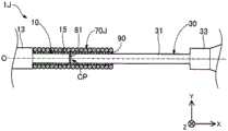
图16是第十实施方式的导丝1J的接置部周边的局部截面图。第十实施方式的导丝1J,在第一实施方式的结构基础上,设有与包覆构件70不同结构的包覆构件70J。包覆构件70J是螺旋状地卷绕线材而形成的大致圆筒形状的线圈体。包覆构件70J可以是由一根线材构成的单线圈,也可以是由使用了多根线材的绞线构成的中空绞线线圈。此外,包覆构件70J也可以是图10说明的多股线圈。构成包覆构件70J的线材的材料可以与线圈体20的线材21的材料相同,也可以不同。如此,包覆构件70J的形状不限于管形状,可以任意改变。即使在第十实施方式的导丝1J中,也可以获得与第一及第四实施方式相同的效果。FIG. 16 is a partial cross-sectional view around the receiving portion of the
<第十一实施方式><Eleventh Embodiment>
图17是第十一实施方式的导丝1K的包覆构件70附近的放大图。第十一实施方式的导丝1K,在第三实施方式的结构基础上,设有与内侧包覆构件40不同结构的内侧包覆构件40K。内侧包覆构件40K与包覆构件70相同,是形成为具有恒定外径的管形状(大致圆筒形状)的金属制管状构件。内侧包覆构件40K可以由与包覆构件70相同的材料制成,也可以由不同的材料制成。内侧包覆构件40K的前端侧,通过铆接前端部40d而固定在第一芯轴10B的第一端部侧细径部15e上。内侧包覆构件40K的基端侧,通过铆接基端部40p而固定在第二芯轴30B的第二端部侧细径部31e上。在图示的示例中,内侧包覆构件40K的内侧,是未配置接合剂的空隙。如此,内侧包覆构件40K也可以通过接合剂以外的方法固定于第一及第二芯轴10B、30B。即使在第十一实施方式的导丝1K中,也可以获得与第一及第三实施方式相同的效果。FIG. 17 is an enlarged view of the vicinity of the covering
<本实施方式的变形例><Modification of this embodiment>
本发明不限于上述实施方式,能够在不脱离其主旨的范围内以各种方式实施,例如也可以是如下所述的变形。The present invention is not limited to the above-described embodiments, and can be implemented in various forms without departing from the gist thereof. For example, modifications as described below are also possible.
[变形例1][Modification 1]
在上述第一~第十一实施方式中,例示了导丝1、1A~1K的结构。但是,导丝的结构可以进行各种改变。例如,对于上述各实施方式的导丝,以其作为将导管插入血管时使用的医疗器具进行了说明,但也可以构成为插入人体内各器官的导丝,人体内各器官包括淋巴系统、胆道系统、泌尿系统、呼吸道系统、消化系统、分泌腺和生殖器官等。例如,导丝可以是整个第一及第二芯轴(换言之,从第一芯轴的前端部到第二芯轴的基端部的整体)被线圈体覆盖的结构。例如,导丝也可以在前端侧预先弯曲的状态下被产品化。In the above-mentioned first to eleventh embodiments, the structures of the
[变形例2][Modification 2]
在上述第一~第十一实施方式中,例示了第一及第二芯轴10、10A、10B、10E~10G、30、30A、30B、30E~30G的结构。但是,第一芯轴及第二芯轴的结构可以进行各种变化。例如,第一芯轴可以不设置前端细径部或前端缩径部,第二芯轴也可以不设置基端缩径部或基端粗径部。例如,第一芯轴可以由超弹性材料以外的各种材料制成,第二芯轴可以由比第一芯轴难以塑性变形的材料制成。第一及第二芯轴也可以由相同的材料制成。例如,第一及第二芯轴的各部的横截面形状也可以不是大致圆形形状,还可以采用各种形状(例如大致矩形形状、大致椭圆形形状等)。In the first to eleventh embodiments described above, the configurations of the first and
[变形例3][Modification 3]
在上述第一~第十一实施方式中,示出了线圈体20的结构的一个示例。但是,线圈体的结构可以进行各种改变。例如,线圈体可以构成为在相邻线材之间没有间隙的紧密卷绕,也可以形成为在相邻线材之间具有间隙的疏松卷绕,还可以是紧密卷绕和疏松卷绕混合的结构。此外,线圈体还可以包括树脂层,该树脂层由例如具有疏水性的树脂材料、具有亲水性的树脂材料、或它们的混合物涂覆而成。例如,线圈体的线材的横截面形状还可以不是大致圆形。An example of the structure of the
[变形例4][Modification 4]
在上述第一~第十一实施方式中,示出了内侧包覆构件40、40C、40K的结构的一个示例。但是,内侧包覆构件的结构可以进行各种改变。例如,内侧包覆构件也可以由金属以外的材料(例如树脂等)制成。例如,内侧包覆构件也可以设置用于使接合剂容易附着的基底层。例如,在内侧包覆构件为管形状的情况下,横截面的形状也可以是椭圆筒状。例如,在内侧包覆构件为线圈体的情况下,线材的横截面形状可以不是大致圆形,而可以采用大致椭圆形、大致矩形等形状。In the first to eleventh embodiments described above, examples of the structures of the
[变形例5][Modification 5]
在上述第一~第十一实施方式中,示出了包覆构件70、70A、70C、70J的结构的一个示例。但是,包覆构件的结构可以进行各种改变。例如,包覆构件也可以由金属以外的材料(例如树脂等)制成。例如,包覆构件可以是与第二芯轴相比弯曲刚性大致相同或更高的结构,也可以是具有不同于第一芯轴的弹性模量的结构。In the first to eleventh embodiments described above, examples of the structures of the covering
[变形例6][Modification 6]
上述第一~第十一实施方式的导丝1、1A~1K的结构、以及上述变形例1~5的导丝的结构还可以适当组合。例如,在第三~第五实施方式的导丝1B~1D(设有第一端部侧细径部、第一中间细径部的结构)中,也可以采用在第六实施方式中描述的第一及第二细径部的长度(L61=L62)、或第七实施方式中描述的第一及第二细径部的长度(L71>L72)。例如,在第三~第五实施方式的导丝1B~1D(具有第一端部侧细径部、第一中间细径部的结构)中,可以采用在第八实施方式中描述的设有第一及第二中间部的结构,也可以采用第九实施方式中描述的接合层。The configurations of the
以上基于实施方式、变形例对本发明进行了说明,但上述形态的实施方式是为了便于理解本发明的示例,并不用以限制本发明。凡在本发明的精神以及权利要求请求范围之内所作的变形、改进以及等同替换等,均应包含在本发明的保护范围之内。另外,其技术特征如果在本说明书中没有被描述为不可或缺,则可以进行适当删除。As mentioned above, although this invention was demonstrated based on embodiment and a modification, the embodiment of the said aspect is an example for facilitating understanding of this invention, and does not limit this invention. All modifications, improvements and equivalent replacements made within the spirit of the present invention and the scope of the claims shall be included in the protection scope of the present invention. In addition, if its technical features are not described as indispensable in this specification, they may be appropriately deleted.
附图标记说明Explanation of reference signs
1、1A~1K…导丝1. 1A~1K…guide wire
10、10A、10B、10E~10G…第一芯轴10, 10A, 10B, 10E~10G...the first mandrel
11…前端细径部11...Small diameter part at front end
12…前端缩径部12...Front end reducing part
13…第一粗径部13...The first large diameter part
14…第一中间部14...first middle part
15、15A、15E、15F…第一细径部15, 15A, 15E, 15F...the first small diameter part
15e…第一端部侧细径部15e...Small diameter portion on the first end side
15m…第一中间细径部15m...The first intermediate narrow diameter part
20…线圈体20…coil body
21…线材21...wire
30、30A、30B、30E~30G…第二芯轴30, 30A, 30B, 30E~30G...the second mandrel
31、31A、31E、31F…第二细径部31, 31A, 31E, 31F...the second narrow diameter part
31e…第二端部侧细径部31e...2nd end side small diameter part
31m…第二中间细径部31m...Second intermediate narrow diameter part
32…第二中间部32…Second middle part
33…第二粗径部33...Second large diameter part
34…基端缩径部34...Base end reducing part
35…基端粗径部35...Base end large diameter part
40、40C、40K…内侧包覆构件40, 40C, 40K... Inner cladding member
41…线材41...wire
51…前端侧固定部51...Front side fixing part
52…基端侧固定部52...Base end side fixing part
61…中间固定部61...Middle fixed part
70、70A、70C、70J…包覆构件70, 70A, 70C, 70J... cladding member
81…接合剂81…bonding agent
90、90H…接合剂90, 90H...bonding agent
91、92、93…接合剂91, 92, 93...bonding compound
95…内侧固定部95...Inner fixed part
Claims (10)
Applications Claiming Priority (1)
| Application Number | Priority Date | Filing Date | Title |
|---|---|---|---|
| PCT/JP2018/027068WO2020016986A1 (en) | 2018-07-19 | 2018-07-19 | Guide wire and guide wire manufacturing method |
Publications (2)
| Publication Number | Publication Date |
|---|---|
| CN112368043A CN112368043A (en) | 2021-02-12 |
| CN112368043Btrue CN112368043B (en) | 2023-05-02 |
Family
ID=69164848
Family Applications (1)
| Application Number | Title | Priority Date | Filing Date |
|---|---|---|---|
| CN201880095113.0AActiveCN112368043B (en) | 2018-07-19 | 2018-07-19 | Guide wire and method of manufacturing guide wire |
Country Status (5)
| Country | Link |
|---|---|
| US (1) | US20210128887A1 (en) |
| EP (1) | EP3824938A4 (en) |
| JP (1) | JP7175311B2 (en) |
| CN (1) | CN112368043B (en) |
| WO (1) | WO2020016986A1 (en) |
Families Citing this family (4)
| Publication number | Priority date | Publication date | Assignee | Title |
|---|---|---|---|---|
| JP2022190427A (en)* | 2021-06-14 | 2022-12-26 | 朝日インテック株式会社 | guide wire |
| CN115055771B (en)* | 2021-10-22 | 2024-03-01 | 美度可医疗科技(上海)有限公司 | Guide wire with high safety performance and high operability and welding method |
| WO2025100048A1 (en)* | 2023-11-09 | 2025-05-15 | 朝日インテック株式会社 | Guide wire |
| CN119679546B (en)* | 2025-02-25 | 2025-05-02 | 北京华脉泰科医疗器械股份有限公司 | Aortic stent graft in situ fenestration system |
Citations (2)
| Publication number | Priority date | Publication date | Assignee | Title |
|---|---|---|---|---|
| WO2003030982A2 (en)* | 2001-10-05 | 2003-04-17 | Boston Scientific Limited | Composite guidewire |
| CN107666936A (en)* | 2015-04-14 | 2018-02-06 | 艾博特心血管系统公司 | For improving the mechanism across the stiffness transition at different-metal material welding junction surface |
Family Cites Families (16)
| Publication number | Priority date | Publication date | Assignee | Title |
|---|---|---|---|---|
| US5109867A (en)* | 1991-04-19 | 1992-05-05 | Target Therapeutics | Extendable guidewire assembly |
| JPH1157014A (en)* | 1997-08-11 | 1999-03-02 | Terumo Corp | Guide wire |
| US6001068A (en)* | 1996-10-22 | 1999-12-14 | Terumo Kabushiki Kaisha | Guide wire having tubular connector with helical slits |
| US5980471A (en) | 1997-10-10 | 1999-11-09 | Advanced Cardiovascular System, Inc. | Guidewire with tubular connector |
| JP2004016359A (en) | 2002-06-13 | 2004-01-22 | Terumo Corp | Guide wire |
| US6866642B2 (en)* | 2002-11-25 | 2005-03-15 | Advanced Cardiovascular Systems, Inc. | Enhanced method for joining two core wires |
| US20040167441A1 (en)* | 2003-02-26 | 2004-08-26 | Reynolds Brian R. | Composite medical device |
| US7182735B2 (en)* | 2003-02-26 | 2007-02-27 | Scimed Life Systems, Inc. | Elongated intracorporal medical device |
| JP2006122311A (en)* | 2004-10-28 | 2006-05-18 | Tokusen Kogyo Co Ltd | Guide wire |
| JP4829684B2 (en)* | 2006-06-02 | 2011-12-07 | 株式会社エフエムディ | Medical guidewire |
| JP5214878B2 (en)* | 2006-12-28 | 2013-06-19 | テルモ株式会社 | Guide wire |
| US8206837B2 (en)* | 2007-01-12 | 2012-06-26 | Terumo Kabushiki Kaisha | Interventional medical device |
| JP2014100300A (en)* | 2012-11-20 | 2014-06-05 | Asahi Intecc Co Ltd | Guide wire |
| US20150094690A1 (en)* | 2013-09-30 | 2015-04-02 | Abbott Cardiovasular Systems Inc. | Guidewire with varying properties |
| JP6586425B2 (en) | 2014-04-21 | 2019-10-02 | コーニンクレッカ フィリップス エヌ ヴェKoninklijke Philips N.V. | Intravascular device, system and method having separate sections with core elements engaged |
| JP6399460B2 (en)* | 2016-09-30 | 2018-10-03 | 株式会社エフエムディ | Medical guidewire |
- 2018
- 2018-07-19JPJP2020530805Apatent/JP7175311B2/enactiveActive
- 2018-07-19EPEP18927045.7Apatent/EP3824938A4/enactivePending
- 2018-07-19CNCN201880095113.0Apatent/CN112368043B/enactiveActive
- 2018-07-19WOPCT/JP2018/027068patent/WO2020016986A1/ennot_activeCeased
- 2021
- 2021-01-15USUS17/150,019patent/US20210128887A1/enactivePending
Patent Citations (2)
| Publication number | Priority date | Publication date | Assignee | Title |
|---|---|---|---|---|
| WO2003030982A2 (en)* | 2001-10-05 | 2003-04-17 | Boston Scientific Limited | Composite guidewire |
| CN107666936A (en)* | 2015-04-14 | 2018-02-06 | 艾博特心血管系统公司 | For improving the mechanism across the stiffness transition at different-metal material welding junction surface |
Also Published As
| Publication number | Publication date |
|---|---|
| EP3824938A4 (en) | 2022-03-30 |
| EP3824938A1 (en) | 2021-05-26 |
| JPWO2020016986A1 (en) | 2021-06-24 |
| US20210128887A1 (en) | 2021-05-06 |
| CN112368043A (en) | 2021-02-12 |
| JP7175311B2 (en) | 2022-11-18 |
| WO2020016986A1 (en) | 2020-01-23 |
Similar Documents
| Publication | Publication Date | Title |
|---|---|---|
| CN112368043B (en) | Guide wire and method of manufacturing guide wire | |
| JP7269934B2 (en) | guide wire | |
| WO2020003502A1 (en) | Guide wire | |
| JP7546454B2 (en) | Guidewires | |
| WO2024116319A1 (en) | Medical device and method of manufacturing medical device | |
| WO2020003501A1 (en) | Guide wire | |
| CN112334180B (en) | guide wire | |
| JP7261879B2 (en) | guide wire | |
| JP7389123B2 (en) | guide wire | |
| JP7184890B2 (en) | guide wire | |
| JP7256582B2 (en) | guide wire | |
| JP7551285B2 (en) | Guidewires | |
| JP7366598B2 (en) | guide wire | |
| JP2025101070A (en) | Guide wire | |
| CN118662759A (en) | Vascular intervention guide wire | |
| CN116472083A (en) | guide wire | |
| JP2022166396A (en) | guide wire |
Legal Events
| Date | Code | Title | Description |
|---|---|---|---|
| PB01 | Publication | ||
| PB01 | Publication | ||
| SE01 | Entry into force of request for substantive examination | ||
| SE01 | Entry into force of request for substantive examination | ||
| GR01 | Patent grant | ||
| GR01 | Patent grant |