CN112363126A - Linear array-based trajectory target echo signal simulation method - Google Patents
Linear array-based trajectory target echo signal simulation methodDownload PDFInfo
- Publication number
- CN112363126A CN112363126ACN202011058812.3ACN202011058812ACN112363126ACN 112363126 ACN112363126 ACN 112363126ACN 202011058812 ACN202011058812 ACN 202011058812ACN 112363126 ACN112363126 ACN 112363126A
- Authority
- CN
- China
- Prior art keywords
- signal
- radar
- target
- simulator
- antenna
- Prior art date
- Legal status (The legal status is an assumption and is not a legal conclusion. Google has not performed a legal analysis and makes no representation as to the accuracy of the status listed.)
- Granted
Links
- 238000000034methodMethods0.000titleclaimsabstractdescription29
- 238000004088simulationMethods0.000titleclaimsabstractdescription23
- 238000006243chemical reactionMethods0.000claimsabstractdescription26
- 238000012545processingMethods0.000claimsabstractdescription26
- 230000005855radiationEffects0.000claimsabstractdescription9
- 238000001914filtrationMethods0.000claimsabstractdescription6
- 230000003321amplificationEffects0.000claimsabstractdescription5
- 238000003199nucleic acid amplification methodMethods0.000claimsabstractdescription5
- 238000005070samplingMethods0.000claimsdescription11
- 229920006395saturated elastomerPolymers0.000claimsdescription3
- 230000010355oscillationEffects0.000claims2
- 238000005286illuminationMethods0.000claims1
- 230000000007visual effectEffects0.000claims1
- 238000005516engineering processMethods0.000abstractdescription2
- 230000033001locomotionEffects0.000description5
- 230000005540biological transmissionEffects0.000description4
- 238000013461designMethods0.000description4
- 238000010586diagramMethods0.000description4
- 230000001133accelerationEffects0.000description2
- 238000010276constructionMethods0.000description2
- 230000000694effectsEffects0.000description2
- 238000005259measurementMethods0.000description2
- 238000012360testing methodMethods0.000description2
- 238000004364calculation methodMethods0.000description1
- 238000001514detection methodMethods0.000description1
- 238000011156evaluationMethods0.000description1
- 238000002474experimental methodMethods0.000description1
- 238000013213extrapolationMethods0.000description1
- 239000000463materialSubstances0.000description1
- 238000010187selection methodMethods0.000description1
- 238000012549trainingMethods0.000description1
- 238000012795verificationMethods0.000description1
Images


Classifications
- G—PHYSICS
- G01—MEASURING; TESTING
- G01S—RADIO DIRECTION-FINDING; RADIO NAVIGATION; DETERMINING DISTANCE OR VELOCITY BY USE OF RADIO WAVES; LOCATING OR PRESENCE-DETECTING BY USE OF THE REFLECTION OR RERADIATION OF RADIO WAVES; ANALOGOUS ARRANGEMENTS USING OTHER WAVES
- G01S7/00—Details of systems according to groups G01S13/00, G01S15/00, G01S17/00
- G01S7/02—Details of systems according to groups G01S13/00, G01S15/00, G01S17/00 of systems according to group G01S13/00
- G01S7/40—Means for monitoring or calibrating
- G01S7/4052—Means for monitoring or calibrating by simulation of echoes
Landscapes
- Engineering & Computer Science (AREA)
- Computer Networks & Wireless Communication (AREA)
- Physics & Mathematics (AREA)
- General Physics & Mathematics (AREA)
- Radar, Positioning & Navigation (AREA)
- Remote Sensing (AREA)
- Radar Systems Or Details Thereof (AREA)
Abstract
Translated fromChinese
Description
Translated fromChinese技术领域technical field
本发明涉及一种基于线阵的弹道目标回波信号模拟方法,属于雷达模拟测试技术领域。The invention relates to a linear array-based ballistic target echo signal simulation method, which belongs to the technical field of radar simulation testing.
背景技术Background technique
弹道目标回波信号模拟器通过模拟真实弹道目标的雷达回波,检验雷达的目标捕获、跟踪和外推的能力,便于雷达可用性的评估和野战部队的平时训练,有利于节省大量的人力、物力和时间。The ballistic target echo signal simulator tests the radar's target acquisition, tracking and extrapolation capabilities by simulating the radar echo of a real ballistic target, which is convenient for the evaluation of radar availability and the peacetime training of field troops, and is conducive to saving a lot of manpower and material resources and time.
模拟器天线形式的选择决定了弹道目标回波信号模拟的有效性和真实性。采用单个天线单元仰角沿导轨运动的方式可以模拟弹道目标仰角的运动,仅需一根射频电缆,难点在于天线折叠结构的设计、导轨的设计和天线单元沿导轨运动速度的限制(安全速度在1m/s以下)。另外,电机启动时电流很大,可能造成直流电源的电压下降,使其他电路不能正常工作;电机开始和终止运动具有安全隐患,必须考虑安全保护;电机加速减速过程使得匀速运动的行程范围变小,天线运动行程要考虑加速减速段,增加了系统的复杂性和技术难度。The choice of the simulator antenna form determines the effectiveness and authenticity of the ballistic target echo signal simulation. The movement of the elevation angle of the ballistic target can be simulated by moving the elevation angle of a single antenna unit along the guide rail. Only one RF cable is needed. The difficulty lies in the design of the antenna folding structure, the design of the guide rail and the limitation of the moving speed of the antenna unit along the guide rail (the safe speed is 1m). /s or less). In addition, when the motor starts, the current is very large, which may cause the voltage of the DC power supply to drop, making other circuits unable to work normally; the motor starts and stops the movement with potential safety hazards, and safety protection must be considered; the acceleration and deceleration process of the motor reduces the travel range of uniform motion. , the acceleration and deceleration sections should be considered in the antenna movement stroke, which increases the complexity and technical difficulty of the system.
模拟器天线的一种可选方案是采用天线单元阵列,每个辐射单元需要相应的射频电缆、射频电子开关等。选择天线单元阵列虽然成本有所增加,但是设备安全可靠,模拟的目标速度能够满足弹道目标的实际速度要求。因此,天线单元阵列的位置、架高、阵列长度、单元数和单元间距的计算以及弹道数据的产生方法,成为弹道目标回波信号模拟器的关键。An alternative to the simulator antenna is to use an array of antenna elements, each radiating element requires a corresponding RF cable, RF electronic switch, etc. Although the cost of selecting the antenna element array has increased, the equipment is safe and reliable, and the simulated target speed can meet the actual speed requirements of the ballistic target. Therefore, the calculation of the position, height, length of the antenna element array, the number of elements and the distance between the elements and the method of generating the ballistic data become the key to the echo signal simulator of the ballistic target.
发明内容SUMMARY OF THE INVENTION
本发明所要解决的技术问题是提供一种基于线阵的弹道目标回波信号模拟方法,其核心技术在于采用天线单元组成的线阵模拟弹道目标的运动,天线单元之间通过开关矩阵和幅相控制模拟弹道目标的角度位置变化,通过数字信号处理模拟目标的距离位置变化以及径向速度变化,解决了雷达外场实验中雷达系统性能验证的问题。The technical problem to be solved by the present invention is to provide a method for simulating the echo signal of a ballistic target based on a linear array. The angular position change of the simulated ballistic target is controlled, and the distance position change and radial velocity change of the simulated target are processed by digital signal, which solves the problem of the performance verification of the radar system in the radar field experiment.
本发明为解决上述技术问题采用以下技术方案:本发明于提出了一种基于线阵的弹道目标回波信号模拟方法,通过基于线阵的雷达回波模型的构建,实现基于线阵的弹道目标回波信号模拟方法,其中,基于线阵的雷达回波模型包括雷达、雷达天线望远镜和模拟器;In order to solve the above technical problems, the present invention adopts the following technical solutions: the present invention proposes a linear array-based ballistic target echo signal simulation method, through the construction of the linear array-based radar echo model, the linear array-based ballistic target An echo signal simulation method, wherein the radar echo model based on a linear array includes a radar, a radar antenna telescope and a simulator;
所述雷达垂直地面摆放;The radar is placed vertically on the ground;
所述模拟器与雷达分开相对摆放;The simulator and the radar are placed opposite to each other separately;
所述雷达天线望远镜位于雷达天线中心正下方;The radar antenna telescope is located just below the center of the radar antenna;
所述模拟器包括天线单元阵列、射频电子开关、射频收发组件、A/D器件、数字信号处理模块和D/A器件,模拟器中的各个组件通过稳幅稳相电缆相连接;The simulator includes an antenna unit array, a radio frequency electronic switch, a radio frequency transceiver component, an A/D device, a digital signal processing module and a D/A device, and each component in the simulator is connected by a stable amplitude and phase cable;
所述天线单元阵列垂直地面摆放,天线单元阵列中的各个天线单元呈直线型排列;The antenna unit array is placed vertically on the ground, and each antenna unit in the antenna unit array is arranged in a straight line;
所述天线单元阵列与射频电子开关信号互通,射频电子开关与射频收发组件信号互通,射频收发组件将处理后的模拟信号传输至A/D器件,A/D器件将模拟信号转换成数字信号之后传入数字信号处理模块,数字信号处理模块将处理后的数字信号传入D/A器件,获得模拟信号,D/A器件将模拟信号传入射频收发组件;The antenna unit array communicates with the radio frequency electronic switch signal, the radio frequency electronic switch communicates with the radio frequency transceiver component, and the radio frequency transceiver component transmits the processed analog signal to the A/D device, and the A/D device converts the analog signal into a digital signal. The digital signal processing module transmits the processed digital signal to the D/A device to obtain an analog signal, and the D/A device transmits the analog signal to the RF transceiver component;
基于线阵的弹道目标回波信号模拟方法,通过步骤1至步骤7来实现:The linear array-based ballistic target echo signal simulation method is implemented through steps 1 to 7:
步骤1.通过雷达的天线口径和工作波长,获得模拟器与雷达的距离;Step 1. Obtain the distance between the simulator and the radar through the antenna aperture and working wavelength of the radar;
步骤2.通过雷达天线中心距离地面的高度、雷达搜索波束仰角和雷达跟踪波束仰角,结合模拟器与雷达的距离,获得模拟器天线单元阵列的架设高度和长度;Step 2. Through the height of the radar antenna center from the ground, the radar search beam elevation angle and the radar tracking beam elevation angle, combined with the distance between the simulator and the radar, the erection height and length of the simulator antenna unit array are obtained;
步骤3.根据模拟器相邻天线单元对雷达的视角,确定模拟器各天线单元间距和天线单元阵列中的天线单元个数;Step 3. Determine the distance between each antenna element of the simulator and the number of antenna elements in the antenna element array according to the angle of view of the adjacent antenna elements of the simulator to the radar;
步骤4.雷达发射雷达辐射信号到达模拟器目标天线单元阵列,获得目标模拟信号然后进入射频收发组件;具体步骤如下:Step 4. The radar transmits the radar radiation signal to the target antenna unit array of the simulator, obtains the target analog signal and then enters the RF transceiver component; the specific steps are as follows:
步骤4-1.将雷达天线望远镜对准模拟器的第一个目标天线单元,确定模拟器中天线单元阵列中的各目标天线单元对雷达天线中心的仰角;Step 4-1. Aim the radar antenna telescope at the first target antenna unit of the simulator, and determine the elevation angle of each target antenna unit in the antenna unit array in the simulator to the center of the radar antenna;
步骤4-2.根据目标模拟轨迹的空间位置相对雷达的仰角值,通过射频电子开关选择对应仰角的模拟器天线单元;Step 4-2. According to the elevation angle value of the radar relative to the spatial position of the target simulated trajectory, select the simulator antenna unit corresponding to the elevation angle through the radio frequency electronic switch;
步骤4-3.射频电子开关与接收机接通并与发射链路断开,发射输出接负载。Step 4-3. The RF electronic switch is connected to the receiver and disconnected from the transmission link, and the transmission output is connected to the load.
步骤5.目标模拟信号首先经过射频收发组件做变频处理,获得目标模拟信号的模拟中频信号,然后经过A/D器件做信号模数转换处理,获得目标模拟信号的数字中频信号;具体步骤如下:Step 5. The target analog signal first undergoes frequency conversion processing by the radio frequency transceiver component to obtain the analog intermediate frequency signal of the target analog signal, and then performs signal analog-to-digital conversion processing through the A/D device to obtain the digital intermediate frequency signal of the target analog signal; The specific steps are as follows:
步骤5-1.目标模拟信号先经接收衰减器调整信号电平,防止模拟器接收机饱和;Step 5-1. The target analog signal first adjusts the signal level through the receiving attenuator to prevent the simulator receiver from being saturated;
步骤5-2.接收衰减器的输出信号先与第一本振信号混频滤波,再与第二本振信号混频滤波,采用两次变频的方案得到目标模拟信号的模拟中频信号;Step 5-2. The output signal of the receiving attenuator is first mixed and filtered with the first local oscillator signal, and then mixed and filtered with the second local oscillator signal, and the analog intermediate frequency signal of the target analog signal is obtained by using the scheme of twice frequency conversion;
步骤5-3.目标模拟信号的模拟中频信号送入A/D器件进行模数转换,得到目标模拟信号的数字中频信号。Step 5-3. The analog intermediate frequency signal of the target analog signal is sent to the A/D device for analog-to-digital conversion to obtain the digital intermediate frequency signal of the target analog signal.
步骤6.通过步骤6-1至步骤6-5,将目标模拟信号的数字中频信号转换为目标回波信号的模拟中频信号,具体步骤如下:Step 6. Convert the digital intermediate frequency signal of the target analog signal into the analog intermediate frequency signal of the target echo signal through steps 6-1 to 6-5, and the specific steps are as follows:
步骤6-1.根据目标模拟信号的数字中频信号的中心频率和数字采样率,完成数字下变频处理,得到目标模拟信号的数字基带信号;Step 6-1. According to the center frequency and digital sampling rate of the digital intermediate frequency signal of the target analog signal, the digital down-conversion process is completed, and the digital baseband signal of the target analog signal is obtained;
步骤6-2.对目标模拟信号的数字基带信号进行存储和包络检测,进行目标模拟信号的数字基带信号的雷达主波束信号的判定;Step 6-2. Perform storage and envelope detection on the digital baseband signal of the target analog signal, and determine the radar main beam signal of the digital baseband signal of the target analog signal;
步骤6-3.对判定为雷达主波束照射目标的目标模拟信号的数字基带信号进行多普勒调制和数字延时处理得到目标回波信号的数字基带信号;Step 6-3. Doppler modulation and digital delay processing are performed on the digital baseband signal of the target analog signal determined to be the radar main beam irradiation target to obtain the digital baseband signal of the target echo signal;
步骤6-4.经过步骤6-3处理后的目标回波信号的数字基带信号经过正交调制,得到目标回波信号的数字中频信号;Step 6-4. The digital baseband signal of the target echo signal processed in step 6-3 is subjected to quadrature modulation to obtain a digital intermediate frequency signal of the target echo signal;
步骤6-5.目标回波信号的数字中频信号送入D/A器件进行数模转换,得到目标回波信号的模拟中频信号;Step 6-5. The digital intermediate frequency signal of the target echo signal is sent to the D/A device for digital-to-analog conversion to obtain the analog intermediate frequency signal of the target echo signal;
步骤7.对目标回波信号的模拟中频信号进行变频放大和辐射,获得目标回波模拟信号,具体步骤如下:Step 7. Perform frequency conversion amplification and radiation on the analog intermediate frequency signal of the target echo signal to obtain the target echo analog signal. The specific steps are as follows:
步骤7-1.将目标回波信号的模拟中频信号先与第二本振信号混频滤波,再与第一本振信号混频滤波,产生模拟射频回波信号,对模拟射频回波信号进行功率放大,得到目标模拟回波信号;Step 7-1. Mix and filter the analog IF signal of the target echo signal with the second local oscillator signal first, and then mix and filter with the first local oscillator signal to generate an analog radio frequency echo signal, and perform the analog radio frequency echo signal. Amplify the power to obtain the target analog echo signal;
步骤7-2.射频电子开关与发射链路接通并与接收机断开,接收输入接负载;Step 7-2. The radio frequency electronic switch is connected to the transmitting link and disconnected from the receiver, and the receiving input is connected to the load;
步骤7-3.选择目标模拟轨迹对应仰角位置的天线单元将目标模拟回波信号辐射出去。Step 7-3. Select the antenna unit at the elevation angle position corresponding to the simulated target trajectory to radiate the simulated echo signal of the target.
作为本发明的一种优选方案:步骤1中,根据雷达工作波长λ和雷达天线口径D,得到需要满足如下公式的模拟器与雷达的距离:As a preferred solution of the present invention: in step 1, according to the radar operating wavelength λ and the radar antenna aperture D, obtain the distance between the simulator and the radar that needs to satisfy the following formula:

其中,R为模拟器与雷达的距离,k为预设常数,1≤k≤2。作为本发明的一种优选方案:步骤2中模拟器中天线单元阵列架设高度和长度通过如下公式获取:Among them, R is the distance between the simulator and the radar, and k is a preset constant, 1≤k≤2. As a preferred solution of the present invention: in step 2, the erection height and length of the antenna element array in the simulator are obtained by the following formula:
h=hr+R tanθminh=hr +R tanθmin
l=R(tanθmax-tanθmin)l=R(tanθmax -tanθmin )
其中,h表示模拟器天线单元阵列架设高度,hr为雷达天线中心离地面的高度,θmin为雷达搜索波束仰角,l表示模拟器天线单元阵列长度,[θmin,θmax]为雷达跟踪波束仰角范围,0<θmin<θmax<90°。Among them, h is the erection height of the simulator antenna unit array, hr is the height of the radar antenna center from the ground, θmin is the radar search beam elevation angle, l is the length of the simulator antenna unit array, [θmin , θmax ] is the radar tracking Beam elevation range, 0 < θmin < θmax <90°.
作为本发明的一种优选方案:步骤3中模拟器各天线单元的间距和阵列单元数,通过如下公式获取:As a preferred solution of the present invention: in step 3, the spacing of each antenna element of the simulator and the number of array elements are obtained by the following formula:
d=R(tan(θmin+Δθ)-tanθmin)d=R(tan(θmin +Δθ)-tanθmin )

其中,d表示模拟器天线单元间距,N表示模拟器天线阵列的天线单元个数,Δθ为模拟器中天线单元阵列中相邻天线单元对雷达的最大视角,int[·]表示上取整。Among them, d represents the distance between the antenna elements of the simulator, N represents the number of antenna elements in the simulator antenna array, Δθ is the maximum viewing angle of the radar from the adjacent antenna elements in the antenna element array in the simulator, and int[·] represents the rounding up.
作为本发明的一种优选方案:步骤4-1中,模拟器天线单元阵列中各天线单元对雷达天线中心的仰角,通过如下公式获取:As a preferred solution of the present invention: in step 4-1, the elevation angle of each antenna element in the simulator antenna element array to the center of the radar antenna is obtained by the following formula:

其中,n=1,2,…,N,θn表示第n个天线单元对雷达天线中心的仰角,θe表示雷达天线望远镜瞄准时的仰角,hs表示望远镜到雷达天线中心的距离。Among them, n=1,2,...,N, θn represents the elevation angle of the nth antenna unit to the center of the radar antenna, θe represents the elevation angle of the radar antenna telescope when aiming, hs represents the distance from the telescope to the center of the radar antenna.
作为本发明的一种优选方案:步骤4-2中射频电子开关根据目标模拟轨迹的空间位置相对雷达的仰角值,通过如下规则选择对应仰角的模拟器天线单元:As a preferred solution of the present invention: in step 4-2, the radio frequency electronic switch selects the simulator antenna unit corresponding to the elevation angle according to the elevation angle value of the radar relative to the spatial position of the target simulated trajectory:
当

作为本发明的一种优选方案:步骤6-2中通过如下规则来进行雷达主波束信号的判定:As a preferred solution of the present invention: in step 6-2, the radar main beam signal is judged by the following rules:
若接收的信号电平as为amax-6dB<as<amax,则判定为雷达主波束照射目标;若接收的信号电平as为as<amax-6dB,则判定为雷达副瓣波束照射目标;其中,amax是雷达波束照射模拟器的第一个天线单元信号电平,单位为dB。If the received signal level as is amax -6dB<as <amax , it is determined that the radar main beam illuminates the target; if the received signal level as is as <amax -6dB, it is determined that the radar is a radar The sidelobe beam illuminates the target; where amax is the signal level of the first antenna element of the radar beam illuminated simulator, in dB.
作为本发明的一种优选方案:步骤6-3中对目标模拟信号的数字基带信号,通过步骤6-3-1到步骤6-3-2来进行多普勒调制和数字延时处理:As a preferred solution of the present invention: in step 6-3, the digital baseband signal of the target analog signal is subjected to Doppler modulation and digital delay processing through steps 6-3-1 to 6-3-2:
步骤6-3-1.获得加入多普勒频率后的信号,表达式如下:Step 6-3-1. Obtain the signal after adding the Doppler frequency, the expression is as follows:
sbase(mTs)=(I1(m)cos(Δφ)-Q1(m)sin(Δφ))+j(I1(m)sin(Δφ)+Q1(m)cos(Δφ))sbase (mTs )=(I1 (m)cos(Δφ)-Q1 (m)sin(Δφ))+j(I1 (m)sin(Δφ)+Q1 (m)cos(Δφ) )
其中,


步骤6-3-2.对进行过多普勒调制后的数字基带信号加入延时,得到处理后的目标回波信号的数字基带信号,表达式如下:Step 6-3-2. Add a delay to the digital baseband signal after Doppler modulation to obtain the digital baseband signal of the processed target echo signal, and the expression is as follows:
s′base(mTs)=sbase(mTs-τTs)s'base (mTs )=sbase (mTs -τTs )
其中,s′base(mTs)表示处理后的目标回波信号的数字基带信号,Ts表示信号采样间隔,m=0,1,2,…表示信号离散采样点,τTs表示延时量,τ为整数。Among them, s'base (mTs ) represents the digital baseband signal of the processed target echo signal, Ts represents the signal sampling interval, m=0, 1, 2, ... represents the discrete sampling points of the signal, and τTs represents the delay amount , τ is an integer.
本发明采用以上技术方案与现有技术相比,具有以下技术效果:Compared with the prior art, the present invention adopts the above technical scheme, and has the following technical effects:
(1)利用天线单元阵列,合理选择阵列天线单元数和单元间距,能够高精度模拟目标的角度位置变化,采用数字信号处理技术能够高精度模拟目标的距离位置变化及径向速度变化,进而能够真实模拟弹道目标的雷达回波;(1) By using the antenna element array, the number of array antenna elements and the element spacing can be reasonably selected, and the angular position change of the target can be simulated with high precision. Digital signal processing technology can be used to simulate the distance position change and radial velocity change of the target with high precision, and then can Real simulation of radar echo of ballistic target;
(2)弹道目标回波信号的产生基于雷达辐射信号经混频滤波和数字下变频的数字基带信号,避免了信号发生器的设计,节省了硬件资源,降低了模拟器设计的复杂性。(2) The generation of the echo signal of the ballistic target is based on the digital baseband signal of the radar radiation signal after mixing filtering and digital down-conversion, which avoids the design of the signal generator, saves the hardware resources, and reduces the complexity of the simulator design.
附图说明Description of drawings
图1是本发明的总流程图;Fig. 1 is the general flow chart of the present invention;
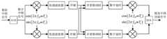
图2是本发明所使用的模拟器原理框图;Fig. 2 is the simulator principle block diagram used in the present invention;
图3是本发明所使用的雷达和模拟器相对位置平面几何示意图;Fig. 3 is the relative position plane geometric schematic diagram of radar and simulator used in the present invention;
图4是本发明所使用的模拟器阵列各天线单元对雷达天线中心仰角的平面几何示意图;Fig. 4 is the plane geometric schematic diagram of each antenna unit of the simulator array used in the present invention to the center elevation angle of the radar antenna;
图5是本发明所使用的数字信号处理原理框图。FIG. 5 is a schematic block diagram of the digital signal processing used in the present invention.
具体实施方式Detailed ways
本发明提出了一种基于线阵的弹道目标回波信号模拟方法,下面结合附图对本发明的技术方案做进一步的详细说明:The present invention proposes a method for simulating a ballistic target echo signal based on a linear array. The technical solution of the present invention will be further described in detail below with reference to the accompanying drawings:
通过基于线阵的雷达回波模型的构建,实现基于线阵的弹道目标回波信号模拟方法,其中,基于线阵的雷达回波模型包括雷达、雷达天线望远镜和模拟器;雷达垂直地面摆放;模拟器与雷达分开相对摆放;雷达天线望远镜位于雷达天线中心正下方;如图2所示,模拟器包括天线单元阵列、射频电子开关、射频收发组件、A/D器件、数字信号处理模块和D/A器件,模拟器中的各个组件通过稳幅稳相电缆相连接;Through the construction of radar echo model based on linear array, the simulation method of ballistic target echo signal based on linear array is realized. The radar echo model based on linear array includes radar, radar antenna telescope and simulator; the radar is placed vertically on the ground ; The simulator and the radar are placed opposite to each other; the radar antenna telescope is located directly below the center of the radar antenna; as shown in Figure 2, the simulator includes an antenna unit array, an RF electronic switch, a RF transceiver component, an A/D device, and a digital signal processing module and D/A devices, each component in the simulator is connected by a stable amplitude and stable phase cable;
天线单元阵列垂直地面摆放,天线单元阵列中的各个天线单元呈直线型排列;The antenna unit array is placed vertically on the ground, and each antenna unit in the antenna unit array is arranged in a straight line;
天线单元阵列与射频电子开关信号互通,射频电子开关与射频收发组件信号互通,射频收发组件将处理后的模拟信号传输至A/D器件,A/D器件将模拟信号转换成数字信号之后传入数字信号处理模块,数字信号处理模块将处理后的数字信号传入D/A器件,获得模拟信号,D/A器件将模拟信号传入射频收发组件;The antenna unit array communicates with the RF electronic switch signal, the RF electronic switch communicates with the RF transceiver component, the RF transceiver component transmits the processed analog signal to the A/D device, and the A/D device converts the analog signal into a digital signal and then transmits it. Digital signal processing module, the digital signal processing module transmits the processed digital signal to the D/A device to obtain an analog signal, and the D/A device transmits the analog signal to the radio frequency transceiver component;
如图1所示,本实施例通过步骤1至步骤7来实现基于线阵的弹道目标回波信号模拟方法。As shown in FIG. 1 , in this embodiment, the method for simulating the echo signal of a ballistic target based on a linear array is implemented through steps 1 to 7 .
步骤1.根据雷达的天线口径和工作波长,获得模拟器与雷达的距离;假设雷达天线口径为D,工作波长为λ,模拟器的位置必须满足雷达天线的准远场条件,即模拟器与雷达的距离需要满足如下公式:Step 1. Obtain the distance between the simulator and the radar according to the antenna diameter and working wavelength of the radar; assuming that the radar antenna diameter is D and the working wavelength is λ, the position of the simulator must meet the quasi-far field conditions of the radar antenna, that is, the distance between the simulator and the radar must be satisfied. The distance of the radar needs to satisfy the following formula:

其中,R为模拟器与雷达的距离,k是一固定的常数,工程经验取值为1~2之间的任意数。Among them, R is the distance between the simulator and the radar, k is a fixed constant, and the engineering experience is an arbitrary number between 1 and 2.
步骤2.如图3所示,通过雷达天线中心距离地面的高度、雷达搜索波束仰角和雷达跟踪波束仰角,结合模拟器与雷达的距离,获得模拟器天线单元阵列的架设高度和长度;Step 2. As shown in Figure 3, through the height of the radar antenna center from the ground, the radar search beam elevation angle and the radar tracking beam elevation angle, combined with the distance between the simulator and the radar, obtain the erection height and length of the simulator antenna unit array;
假设雷达天线中心离地面高度为hr,雷达搜索波束仰角为θmin,则模拟器天线单元阵列架设高度应满足:Assuming that the height of the radar antenna center from the ground is hr , and the elevation angle of the radar search beam is θmin , the erection height of the simulator antenna unit array should satisfy:
h=hr+R tanθminh=hr +R tanθmin
假设雷达跟踪波束仰角范围为[θmin,θmax],其中0<θmin<θmax<90°,则模拟器天线单元阵列长度应满足:Assuming that the radar tracking beam elevation range is [θmin ,θmax ], where 0 < θmin <θmax <90°, the length of the simulator antenna unit array should satisfy:
l=R(tanθmax-tanθmin)l=R(tanθmax -tanθmin )
步骤3.根据模拟器相邻天线单元对雷达的视角,确定模拟器各天线单元间距和天线单元阵列中的天线单元个数;Step 3. Determine the distance between each antenna element of the simulator and the number of antenna elements in the antenna element array according to the angle of view of the adjacent antenna elements of the simulator to the radar;
假设模拟器天线单元间距为d,天线单元阵列垂直放置时,最低的两个天线单元对雷达视角为:Assuming that the distance between the antenna elements of the simulator is d, and the antenna element array is placed vertically, the viewing angles of the two lowest antenna elements to the radar are:

最高的两个天线单元对雷达视角为:The top two antenna units have a radar viewing angle as follows:

若模拟目标运动的效果不影响雷达的跟踪性能,模拟器天线单元间距对雷达的视角应小于雷达跟踪测角的精度。由于Δθ1>Δθ2,选择Δθ1满足小于雷达跟踪测角精度的要求,此时模拟器天线单元阵列中各天线单元的间距为:If the effect of the simulated target motion does not affect the tracking performance of the radar, the distance between the antenna elements of the simulator and the viewing angle of the radar should be smaller than the accuracy of the radar tracking angle measurement. Since Δθ1 >Δθ2 , Δθ1 is selected to meet the requirement of less than radar tracking angle measurement accuracy. At this time, the spacing of each antenna element in the simulator antenna element array is:
d=R(tan(θmin+Δθ)-tanθmin)d=R(tan(θmin +Δθ)-tanθmin )
天线单元阵列中的天线单元数为:The number of antenna elements in the antenna element array is:

其中,Δθ是模拟器相邻天线单元对雷达的最大视角,Δθ=Δθ1,int[·]表示向上取整。Among them, Δθ is the maximum viewing angle of the radar from the adjacent antenna units of the simulator, Δθ=Δθ1 , and int[·] means rounded up.
步骤4.雷达发射雷达辐射信号到达模拟器目标天线单元阵列,获得目标模拟信号然后进入射频收发组件;具体步骤如下:Step 4. The radar transmits the radar radiation signal to the target antenna unit array of the simulator, obtains the target analog signal and then enters the RF transceiver component; the specific steps are as follows:
步骤4-1.如图4所示,将雷达天线望远镜对准模拟器的第一个目标天线单元,确定模拟器中天线单元阵列中的各目标天线单元对雷达天线中心的仰角;Step 4-1. As shown in Figure 4, align the radar antenna telescope at the first target antenna unit of the simulator, and determine the elevation angle of each target antenna unit in the antenna unit array in the simulator to the center of the radar antenna;
以最低的天线单元为参考单元,编号为1,则模拟器阵列各天线单元对雷达天线中心的仰角为Taking the lowest antenna unit as the reference unit, numbered 1, the elevation angle of each antenna unit of the simulator array to the center of the radar antenna is

式中,n=1,2,…,N表示第n个天线单元,θe表示雷达天线望远镜瞄准时的仰角,hs表示望远镜到雷达天线中心的距离。In the formula, n=1,2,...,N represents the nth antenna unit, θe represents the elevation angle when the radar antenna telescope is aimed, hs represents the distance from the telescope to the center of the radar antenna.
步骤4-2.根据目标模拟轨迹的空间位置相对雷达的仰角值,通过射频电子开关选择对应仰角的模拟器天线单元,具体选择方式为:Step 4-2. According to the spatial position of the target simulated trajectory relative to the elevation value of the radar, select the simulator antenna unit corresponding to the elevation angle through the radio frequency electronic switch. The specific selection method is as follows:
记目标某时刻模拟轨迹的空间位置相对雷达的仰角值为θ,当满足

步骤4-3.射频电子开关与接收机接通并与发射链路断开,发射输出接负载。Step 4-3. The RF electronic switch is connected to the receiver and disconnected from the transmission link, and the transmission output is connected to the load.
步骤5.目标模拟信号首先经过射频收发组件做变频处理,获得目标模拟信号的模拟中频信号,然后经过A/D器件做信号模数转换处理,获得目标模拟信号的数字中频信号;具体步骤如下:Step 5. The target analog signal first undergoes frequency conversion processing by the radio frequency transceiver component to obtain the analog intermediate frequency signal of the target analog signal, and then performs signal analog-to-digital conversion processing through the A/D device to obtain the digital intermediate frequency signal of the target analog signal; The specific steps are as follows:
步骤5-1.目标模拟信号先经接收衰减器调整信号电平,防止模拟器接收机饱和;Step 5-1. The target analog signal first adjusts the signal level through the receiving attenuator to prevent the simulator receiver from being saturated;
步骤5-2.接收衰减器的输出信号先与第一本振信号混频滤波,再与第二本振信号混频滤波,采用两次变频的方案得到目标模拟信号的模拟中频信号,表达式如下:Step 5-2. The output signal of the receiving attenuator is first mixed and filtered with the first local oscillator signal, and then mixed and filtered with the second local oscillator signal, and the analog intermediate frequency signal of the target analog signal is obtained by using a twice-frequency conversion scheme, the expression as follows:

其中,A(t)表示信号幅度,fIF表示信号中心频率,
步骤5-3.目标模拟信号的模拟中频信号送入A/D器件进行模数转换,得到目标模拟信号的数字中频信号,表达式如下:Step 5-3. The analog intermediate frequency signal of the target analog signal is sent to the A/D device for analog-to-digital conversion, and the digital intermediate frequency signal of the target analog signal is obtained, and the expression is as follows:

其中,Ts表示信号采样间隔,m=0,1,2,…表示信号离散采样点。Among them, Ts represents the signal sampling interval, and m=0, 1, 2, . . . represents the discrete sampling points of the signal.
步骤6.通过步骤6-1至步骤6-5,将目标模拟信号的数字中频信号转换为目标回波信号的模拟中频信号,具体步骤如下:Step 6. Convert the digital intermediate frequency signal of the target analog signal into the analog intermediate frequency signal of the target echo signal through steps 6-1 to 6-5, and the specific steps are as follows:
步骤6-1.如图5所示,根据目标模拟信号的数字中频信号的中心频率和数字采样率,完成数字下变频处理,得到目标模拟信号的数字基带信号;Step 6-1. As shown in Figure 5, according to the center frequency and digital sampling rate of the digital intermediate frequency signal of the target analog signal, the digital down-conversion process is completed, and the digital baseband signal of the target analog signal is obtained;
数字中频信号乘以频率为fIF的数字本振信号,得到信号的同相分量I(m)和正交分量Q(m),分别表示为:Multiply the digital intermediate frequency signal by the digital local oscillator signal of frequency fIF to obtain the in-phase component I(m) and the quadrature component Q(m) of the signal, which are expressed as:


I(m)和Q(m)经过低通滤波器后可得目标模拟信号的数字基带信号的同相分量和正交分量分别为:After I(m) and Q(m) pass through the low-pass filter, the in-phase component and quadrature component of the digital baseband signal of the target analog signal can be obtained as:


步骤6-2.对目标模拟信号的数字基带信号进行存储和包络检测,进行目标模拟信号的数字基带信号的雷达主波束信号的判定,具体判断方式如下:Step 6-2. Store and detect the envelope of the digital baseband signal of the target analog signal, and determine the radar main beam signal of the digital baseband signal of the target analog signal. The specific judgment method is as follows:
按时间分段将数字基带信号存入存储器,求取每个采样点的信号包络和段内所有点的幅度平均值,并与标定的峰值幅度进行比较,若接收的信号电平as为amax-6dB<as<amax则判定为雷达主波束照射目标;若接收的信号电平为as<amax-6dB则判定为雷达副瓣波束照射目标,接收信号填入噪声,后续的信号处理不进行信号转发。其中,
步骤6-3.对判定为雷达主波束照射目标的目标模拟信号的数字基带信号进行多普勒调制和数字延时处理得到目标回波信号的数字基带信号;Step 6-3. Doppler modulation and digital delay processing are performed on the digital baseband signal of the target analog signal determined to be the radar main beam irradiation target to obtain the digital baseband signal of the target echo signal;
假设模拟目标相对雷达的径向速度矢量为

多普勒频率fd可表示为:The Doppler frequency fd can be expressed as:

当目标接近雷达时,有fd>0;当目标远离雷达时,有fd<0。对数字基带信号I1(m)和Q1(m)依次增加相位Δφ,即可模拟目标的多普勒频率。加入多普勒频率后的信号表达式为:When the target is close to the radar, there is fd >0; when the target is far away from the radar, there is fd <0. The Doppler frequency of the target can be simulated by sequentially increasing the phase Δφ to the digital baseband signals I1 (m) and Q1 (m). The signal expression after adding the Doppler frequency is:
sbase(mTs)=(I1(m)+jQ1(m))exp(jΔφ)=I′1(m)+jQ′1(m)sbase (mTs )=(I1 (m)+jQ1 (m))exp(jΔφ)=I′1 (m)+jQ′1 (m)
其中,
I′1(m)=I1(m)cos(Δφ)-Q1(m)sin(Δφ)I′1 (m)=I1 (m)cos(Δφ)−Q1 (m)sin(Δφ)
Q′1(m)=I1(m)sin(Δφ)+Q1(m)cos(Δφ)Q'1 (m)=I1 (m)sin(Δφ)+Q1 (m)cos(Δφ)
对信号sbase(mTs)进行数字延时,通过寄存器来实现,从而模拟目标与雷达的距离位置变化,延时后信号表达式为:Digitally delay the signal sbase (mTs ) and realize it through a register, so as to simulate the change of the distance and position between the target and the radar. The signal expression after the delay is:
s′base(mTs)=sbase(mTs-τTs)s'base (mTs )=sbase (mTs -τTs )
其中,τTs表示延时量,τ为整数。Among them, τTs represents the delay amount, and τ is an integer.
步骤6-4.经过步骤6-3处理后的目标回波信号的数字基带信号经过正交调制,得到目标回波信号的数字中频信号,信号表达式如下:Step 6-4. The digital baseband signal of the target echo signal processed in step 6-3 is subjected to quadrature modulation to obtain a digital intermediate frequency signal of the target echo signal. The signal expression is as follows:
s′IF(mTs)=s′base(mTs)exp(j2πfIFmTs)=(I1(m-τ)+jQ1(m-τ))exp(jΔφ)exp(j2πfIFmTs)=(I1(m-τ)+jQ1(m-τ))exp(j(2πfIFmTs+Δφ))s'IF (mTs )=s'base (mTs )exp(j2πfIF mTs )=(I1 (m-τ)+jQ1 (m-τ))exp(jΔφ)exp(j2πfIF mTs )=(I1 (m-τ)+jQ1 (m-τ))exp(j(2πfIF mTs +Δφ))
步骤6-5.目标回波信号的数字中频信号送入D/A器件进行数模转换,得到目标回波信号的模拟中频信号;Step 6-5. The digital intermediate frequency signal of the target echo signal is sent to the D/A device for digital-to-analog conversion to obtain the analog intermediate frequency signal of the target echo signal;
步骤7.对目标回波信号的模拟中频信号进行变频放大和辐射,获得目标回波模拟信号,具体步骤如下:Step 7. Perform frequency conversion amplification and radiation on the analog intermediate frequency signal of the target echo signal to obtain the target echo analog signal. The specific steps are as follows:
步骤7-1.将目标回波信号的模拟中频信号先与第二本振信号混频滤波,再与第一本振信号混频滤波,产生模拟射频回波信号,对模拟射频回波信号进行功率放大,得到目标模拟回波信号;Step 7-1. Mix and filter the analog IF signal of the target echo signal with the second local oscillator signal first, and then mix and filter with the first local oscillator signal to generate an analog radio frequency echo signal, and perform the analog radio frequency echo signal. Amplify the power to obtain the target analog echo signal;
步骤7-2.射频电子开关与发射链路接通并与接收机断开,接收输入接负载;Step 7-2. The radio frequency electronic switch is connected to the transmitting link and disconnected from the receiver, and the receiving input is connected to the load;
步骤7-3.选择目标模拟轨迹对应仰角位置的天线单元将目标模拟回波信号辐射出去。Step 7-3. Select the antenna unit at the elevation angle position corresponding to the simulated target trajectory to radiate the simulated echo signal of the target.
上面结合附图对本发明的实施方式作了详细说明,但是本发明并不限于上述实施方式,在本领域普通技术人员所具备的知识范围内,还可以在不脱离本发明宗旨的前提下做出各种变化。The embodiments of the present invention have been described in detail above in conjunction with the accompanying drawings, but the present invention is not limited to the above-mentioned embodiments, and can also be made within the scope of knowledge possessed by those of ordinary skill in the art without departing from the purpose of the present invention. Various changes.
Claims (8)


Priority Applications (1)
| Application Number | Priority Date | Filing Date | Title |
|---|---|---|---|
| CN202011058812.3ACN112363126B (en) | 2020-09-30 | 2020-09-30 | Linear array-based trajectory target echo signal simulation method |
Applications Claiming Priority (1)
| Application Number | Priority Date | Filing Date | Title |
|---|---|---|---|
| CN202011058812.3ACN112363126B (en) | 2020-09-30 | 2020-09-30 | Linear array-based trajectory target echo signal simulation method |
Publications (2)
| Publication Number | Publication Date |
|---|---|
| CN112363126Atrue CN112363126A (en) | 2021-02-12 |
| CN112363126B CN112363126B (en) | 2022-03-04 |
Family
ID=74508239
Family Applications (1)
| Application Number | Title | Priority Date | Filing Date |
|---|---|---|---|
| CN202011058812.3AActiveCN112363126B (en) | 2020-09-30 | 2020-09-30 | Linear array-based trajectory target echo signal simulation method |
Country Status (1)
| Country | Link |
|---|---|
| CN (1) | CN112363126B (en) |
Cited By (4)
| Publication number | Priority date | Publication date | Assignee | Title |
|---|---|---|---|---|
| CN114070868A (en)* | 2021-11-16 | 2022-02-18 | 四川九洲空管科技有限责任公司 | High-speed data transmission system and method for secondary radar and anti-collision system |
| CN114879155A (en)* | 2022-03-18 | 2022-08-09 | 北京遥感设备研究所 | System and method for multi-target continuous data acquisition and automatic attribute marking in main beam |
| CN116359871A (en)* | 2023-03-24 | 2023-06-30 | 上海毫微太科技有限公司 | Signal processing method and image acquisition equipment |
| CN119644273A (en)* | 2024-11-29 | 2025-03-18 | 中国科学院上海微系统与信息技术研究所 | Single-array-element-antenna-based wide-band target radar echo simulation device and method |
Citations (8)
| Publication number | Priority date | Publication date | Assignee | Title |
|---|---|---|---|---|
| CN101872013A (en)* | 2010-06-21 | 2010-10-27 | 河海大学 | Ballistic Trajectory Response Signal Source Signal Generation Method Completed in Digital Domain |
| CN102830388A (en)* | 2011-06-13 | 2012-12-19 | 河海大学 | Method for generating real-time simulation signals of two-dimensional space moving target in digital domain |
| CN203561288U (en)* | 2013-12-28 | 2014-04-23 | 中国人民解放军沈阳炮兵学院 | Small linear array for simulating ballistic target signal generation |
| CN103851960A (en)* | 2013-12-28 | 2014-06-11 | 中国人民解放军沈阳炮兵学院 | Small linear antenna capable of simulating generation of trajectory target signal |
| CN105242243A (en)* | 2015-09-29 | 2016-01-13 | 河海大学 | Broadband receiving digital waveform formation method based on dechirp processing and two-time time delays |
| CN107831479A (en)* | 2017-12-01 | 2018-03-23 | 北京润科通用技术有限公司 | A kind of analogue echoes method and system |
| CN109001705A (en)* | 2018-06-27 | 2018-12-14 | 西安电子科技大学 | Wideband radar three-dimensional interference measures cone target fine motion method for parameter estimation |
| CN110412528A (en)* | 2019-08-02 | 2019-11-05 | 西安邮电大学 | A projectile echo simulation device and simulation method for artillery position reconnaissance and calibration radar |
- 2020
- 2020-09-30CNCN202011058812.3Apatent/CN112363126B/enactiveActive
Patent Citations (8)
| Publication number | Priority date | Publication date | Assignee | Title |
|---|---|---|---|---|
| CN101872013A (en)* | 2010-06-21 | 2010-10-27 | 河海大学 | Ballistic Trajectory Response Signal Source Signal Generation Method Completed in Digital Domain |
| CN102830388A (en)* | 2011-06-13 | 2012-12-19 | 河海大学 | Method for generating real-time simulation signals of two-dimensional space moving target in digital domain |
| CN203561288U (en)* | 2013-12-28 | 2014-04-23 | 中国人民解放军沈阳炮兵学院 | Small linear array for simulating ballistic target signal generation |
| CN103851960A (en)* | 2013-12-28 | 2014-06-11 | 中国人民解放军沈阳炮兵学院 | Small linear antenna capable of simulating generation of trajectory target signal |
| CN105242243A (en)* | 2015-09-29 | 2016-01-13 | 河海大学 | Broadband receiving digital waveform formation method based on dechirp processing and two-time time delays |
| CN107831479A (en)* | 2017-12-01 | 2018-03-23 | 北京润科通用技术有限公司 | A kind of analogue echoes method and system |
| CN109001705A (en)* | 2018-06-27 | 2018-12-14 | 西安电子科技大学 | Wideband radar three-dimensional interference measures cone target fine motion method for parameter estimation |
| CN110412528A (en)* | 2019-08-02 | 2019-11-05 | 西安邮电大学 | A projectile echo simulation device and simulation method for artillery position reconnaissance and calibration radar |
Non-Patent Citations (2)
| Title |
|---|
| 孟路稳等: "弹道导弹目标特性分析及雷达回波模拟", 《电讯技术》* |
| 徐少坤等: "弹道中段微动目标宽带回波模拟", 《宇航学报》* |
Cited By (6)
| Publication number | Priority date | Publication date | Assignee | Title |
|---|---|---|---|---|
| CN114070868A (en)* | 2021-11-16 | 2022-02-18 | 四川九洲空管科技有限责任公司 | High-speed data transmission system and method for secondary radar and anti-collision system |
| CN114070868B (en)* | 2021-11-16 | 2023-11-07 | 四川九洲空管科技有限责任公司 | High-speed data transmission method for secondary radar and collision avoidance system |
| CN114879155A (en)* | 2022-03-18 | 2022-08-09 | 北京遥感设备研究所 | System and method for multi-target continuous data acquisition and automatic attribute marking in main beam |
| CN116359871A (en)* | 2023-03-24 | 2023-06-30 | 上海毫微太科技有限公司 | Signal processing method and image acquisition equipment |
| CN116359871B (en)* | 2023-03-24 | 2024-01-19 | 上海毫微太科技有限公司 | Signal processing method and image acquisition equipment |
| CN119644273A (en)* | 2024-11-29 | 2025-03-18 | 中国科学院上海微系统与信息技术研究所 | Single-array-element-antenna-based wide-band target radar echo simulation device and method |
Also Published As
| Publication number | Publication date |
|---|---|
| CN112363126B (en) | 2022-03-04 |
Similar Documents
| Publication | Publication Date | Title |
|---|---|---|
| CN112363126B (en) | Linear array-based trajectory target echo signal simulation method | |
| Knott | Radar cross section measurements | |
| CN107728127B (en) | Radar simulation test system | |
| US7170440B1 (en) | Linear FM radar | |
| CN109001697B (en) | Multi-target radar echo simulator | |
| CN113608183B (en) | Hypersonic broadband radio frequency target simulation system | |
| CN107340269A (en) | The closely ultra wide band Terahertz 3-D imaging system and method for lossless detection | |
| CN108983240B (en) | Target signal simulation system and method of anti-collision millimeter-wave radar based on quadrature modulation system | |
| CN113835070A (en) | Radar tactical performance detection and anti-interference capability evaluation simulator | |
| CN112684421A (en) | Coherent calibration source system for linear frequency modulation continuous wave radar | |
| CN104849703A (en) | Internal and external field dual-purpose portable interference simulation device | |
| CN103513232A (en) | Fuze body object simulation method and system | |
| CN107121678A (en) | Radar | |
| CN104035080A (en) | A store-and-forward shipboard radar active calibration equipment | |
| CN111624564B (en) | Radar pitching angle target simulation system and method | |
| CN112540353A (en) | Linear array-based ballistic target echo signal simulator and ballistic data generation method | |
| CN116500563A (en) | Semi-physical simulation system of airborne monopulse radar | |
| CN218181089U (en) | Radar complex electromagnetic environment test evaluation system and device | |
| CN110988901A (en) | TDC (time-to-digital converter) combined phase laser ranging method and system | |
| CN203825187U (en) | A store-and-forward shipboard radar active calibration equipment | |
| CN114280606A (en) | Ground microwave deformation monitoring system | |
| CN217932042U (en) | Radar echo and interference simulation device | |
| CN106291527B (en) | Radar installations based on fixed directional antenna broad beam angle measurement | |
| CN115219999B (en) | Broadband low-stray shell simulation system | |
| CN114624703B (en) | Multifunctional meteorological environment parameter measurement side scanning radar and operation method thereof |
Legal Events
| Date | Code | Title | Description |
|---|---|---|---|
| PB01 | Publication | ||
| PB01 | Publication | ||
| SE01 | Entry into force of request for substantive examination | ||
| SE01 | Entry into force of request for substantive examination | ||
| GR01 | Patent grant | ||
| GR01 | Patent grant |