CN112353643B - Ankle joint rehabilitation device - Google Patents
Ankle joint rehabilitation deviceDownload PDFInfo
- Publication number
- CN112353643B CN112353643BCN202011257683.0ACN202011257683ACN112353643BCN 112353643 BCN112353643 BCN 112353643BCN 202011257683 ACN202011257683 ACN 202011257683ACN 112353643 BCN112353643 BCN 112353643B
- Authority
- CN
- China
- Prior art keywords
- wearing
- parts
- drive
- along
- training
- Prior art date
- Legal status (The legal status is an assumption and is not a legal conclusion. Google has not performed a legal analysis and makes no representation as to the accuracy of the status listed.)
- Active
Links
- 210000000544articulatio talocruralisAnatomy0.000titleclaimsdescription42
- 210000002683footAnatomy0.000claimsabstractdescription27
- 239000003638chemical reducing agentSubstances0.000claimsdescription32
- 230000000712assemblyEffects0.000claimsdescription10
- 238000000429assemblyMethods0.000claimsdescription10
- 230000007246mechanismEffects0.000claimsdescription5
- 238000009434installationMethods0.000claimsdescription4
- 230000010355oscillationEffects0.000claimsdescription2
- 210000003423ankleAnatomy0.000abstractdescription10
- 241001227561ValgusSpecies0.000abstractdescription8
- 241000469816VarusSpecies0.000abstractdescription7
- 210000003205muscleAnatomy0.000description10
- 238000010586diagramMethods0.000description9
- 239000000178monomerSubstances0.000description6
- 210000001503jointAnatomy0.000description5
- 230000006378damageEffects0.000description4
- 230000000694effectsEffects0.000description4
- 210000003414extremityAnatomy0.000description4
- 230000036544postureEffects0.000description4
- 230000008859changeEffects0.000description3
- 238000011282treatmentMethods0.000description3
- 206010023230Joint stiffnessDiseases0.000description2
- 206010028289Muscle atrophyDiseases0.000description2
- 206010047249Venous thrombosisDiseases0.000description2
- 210000002414legAnatomy0.000description2
- 210000003041ligamentAnatomy0.000description2
- 210000003141lower extremityAnatomy0.000description2
- 230000020763muscle atrophyEffects0.000description2
- 230000004220muscle functionEffects0.000description2
- 201000000585muscular atrophyDiseases0.000description2
- 238000001356surgical procedureMethods0.000description2
- 230000008961swellingEffects0.000description2
- 210000001519tissueAnatomy0.000description2
- 208000027418Wounds and injuryDiseases0.000description1
- 230000009471actionEffects0.000description1
- 150000001875compoundsChemical class0.000description1
- 230000008094contradictory effectEffects0.000description1
- 239000013013elastic materialSubstances0.000description1
- 210000004744fore-footAnatomy0.000description1
- 230000005484gravityEffects0.000description1
- 210000004394hip jointAnatomy0.000description1
- 208000014674injuryDiseases0.000description1
- 230000009191jumpingEffects0.000description1
- 210000000629knee jointAnatomy0.000description1
- 238000000034methodMethods0.000description1
- 230000001105regulatory effectEffects0.000description1
- 230000001360synchronised effectEffects0.000description1
- 230000009466transformationEffects0.000description1
Images


Classifications
- A—HUMAN NECESSITIES
- A61—MEDICAL OR VETERINARY SCIENCE; HYGIENE
- A61H—PHYSICAL THERAPY APPARATUS, e.g. DEVICES FOR LOCATING OR STIMULATING REFLEX POINTS IN THE BODY; ARTIFICIAL RESPIRATION; MASSAGE; BATHING DEVICES FOR SPECIAL THERAPEUTIC OR HYGIENIC PURPOSES OR SPECIFIC PARTS OF THE BODY
- A61H1/00—Apparatus for passive exercising; Vibrating apparatus; Chiropractic devices, e.g. body impacting devices, external devices for briefly extending or aligning unbroken bones
- A61H1/02—Stretching or bending or torsioning apparatus for exercising
- A61H1/0237—Stretching or bending or torsioning apparatus for exercising for the lower limbs
- A61H1/0266—Foot
- A—HUMAN NECESSITIES
- A61—MEDICAL OR VETERINARY SCIENCE; HYGIENE
- A61H—PHYSICAL THERAPY APPARATUS, e.g. DEVICES FOR LOCATING OR STIMULATING REFLEX POINTS IN THE BODY; ARTIFICIAL RESPIRATION; MASSAGE; BATHING DEVICES FOR SPECIAL THERAPEUTIC OR HYGIENIC PURPOSES OR SPECIFIC PARTS OF THE BODY
- A61H2201/00—Characteristics of apparatus not provided for in the preceding codes
- A61H2201/01—Constructive details
- A61H2201/0157—Constructive details portable
- A—HUMAN NECESSITIES
- A61—MEDICAL OR VETERINARY SCIENCE; HYGIENE
- A61H—PHYSICAL THERAPY APPARATUS, e.g. DEVICES FOR LOCATING OR STIMULATING REFLEX POINTS IN THE BODY; ARTIFICIAL RESPIRATION; MASSAGE; BATHING DEVICES FOR SPECIAL THERAPEUTIC OR HYGIENIC PURPOSES OR SPECIFIC PARTS OF THE BODY
- A61H2201/00—Characteristics of apparatus not provided for in the preceding codes
- A61H2201/12—Driving means
- A61H2201/1207—Driving means with electric or magnetic drive
- A—HUMAN NECESSITIES
- A61—MEDICAL OR VETERINARY SCIENCE; HYGIENE
- A61H—PHYSICAL THERAPY APPARATUS, e.g. DEVICES FOR LOCATING OR STIMULATING REFLEX POINTS IN THE BODY; ARTIFICIAL RESPIRATION; MASSAGE; BATHING DEVICES FOR SPECIAL THERAPEUTIC OR HYGIENIC PURPOSES OR SPECIFIC PARTS OF THE BODY
- A61H2205/00—Devices for specific parts of the body
- A61H2205/12—Feet
Landscapes
- Health & Medical Sciences (AREA)
- Epidemiology (AREA)
- Pain & Pain Management (AREA)
- Physical Education & Sports Medicine (AREA)
- Rehabilitation Therapy (AREA)
- Life Sciences & Earth Sciences (AREA)
- Animal Behavior & Ethology (AREA)
- General Health & Medical Sciences (AREA)
- Public Health (AREA)
- Veterinary Medicine (AREA)
- Rehabilitation Tools (AREA)
Abstract
Description
Translated fromChinese技术领域technical field
本发明涉及康复设备技术领域,具体涉及一种踝关节康复装置。The invention relates to the technical field of rehabilitation equipment, in particular to an ankle joint rehabilitation device.
背景技术Background technique
脚踝是下肢三个主要关节末端的最小关节。尽管脚踝直接与脚相连,所以周围肌肉的力量不如髋关节和膝关节强。脚踝的主要活动范围包括背伸、跖屈、外翻、内翻以及旋转的活动,尤其是在跳跃运动的蹬伸阶段,其中踝关节起着重要作用,其力量直接决定了动作的完成时支撑的稳定性。而正是由于脚踝在人体训练中的常用性以及周围肌肉的相对薄弱性,才导致在训练过程中脚踝极易受伤。The ankle is the smallest joint at the end of the three major joints of the lower body. Although the ankle is directly connected to the foot, the surrounding muscles are not as strong as the hip and knee joints. The main range of motion of the ankle includes dorsiflexion, plantarflexion, valgus, varus and rotation, especially in the kicking and extension stage of jumping movement, in which the ankle joint plays an important role, and its strength directly determines the support when the action is completed. stability. It is precisely because of the common use of the ankle in human training and the relative weakness of the surrounding muscles that the ankle is extremely vulnerable to injury during training.
踝关节康复装置适用于改善关节僵硬,并防止相关腿部肌肉群的肌肉萎缩以及肌肉黏附和韧带粘连,促进手术后患肢的静脉回流并减少肿胀。同时,它可以预防下肢静脉血栓形成,提高肌肉力量和关节活动度,减少周围组织的粘附力,增加关节周围肌肉群的力量,改善关节功能状态,开展肌肉功能锻炼以及与其他康复治疗合作以至于恢复四肢促进功能。The Ankle Rehabilitation Device is indicated to improve joint stiffness and prevent muscle atrophy as well as muscle and ligament adhesions of the relevant leg muscle groups, promote venous return and reduce swelling in the affected limb after surgery. At the same time, it can prevent venous thrombosis of the lower extremities, improve muscle strength and joint mobility, reduce the adhesion of surrounding tissues, increase the strength of muscle groups around the joints, improve the functional state of the joints, carry out muscle function exercises, and cooperate with other rehabilitation treatments to As for the restoration of the function of the limbs.
但是,目前大多踝关节康复机器人可调节的运动方式单一,其运动自由度只能用于背屈/足底屈曲康复训练,不能契合不同患者所需要的训练姿态及对踝关节康复的全范围康复需求或者只能用于背屈/跖屈、内翻/外翻、内旋/外旋的其中两种功能,并不能满足实际康复训练的要求。However, at present, most ankle joint rehabilitation robots have a single adjustable movement mode, and their freedom of movement can only be used for dorsiflexion/plantar flexion rehabilitation training, which cannot meet the training postures required by different patients and the full range of ankle joint rehabilitation. Requirements or can only be used for two of the functions of dorsiflexion/plantarflexion, varus/valgus, internal rotation/external rotation, and cannot meet the requirements of actual rehabilitation training.
发明内容Contents of the invention
本发明的主要目的是提出一种踝关节康复装置,旨在解决传统踝关节康复机器人可调节的运动方式单一的问题。The main purpose of the present invention is to propose an ankle joint rehabilitation device, which aims to solve the problem of single adjustable movement mode of traditional ankle joint rehabilitation robots.
为实现上述目的,本发明提出的一种踝关节康复装置,包括:In order to achieve the above object, a kind of ankle joint rehabilitation device that the present invention proposes, comprises:
基座;base;
固定组件,包括用于供用户的两脚穿戴的两个穿戴部,所述穿戴部活动安装于所述基座,且分别具有沿左右向轴线前后翻转、沿前后向轴线左右翻转以及沿上下向轴线水平摆动的活动行程;以及,The fixed assembly includes two wearing parts for wearing by the user's feet, and the wearing parts are movably installed on the base, and have the functions of turning back and forth along the left-right axis, turning left-right along the front-back axis, and turning up and down along the axis. the active travel of the horizontal oscillation of the axis; and,
驱动装置,设于所述基座,所述驱动装置用以分别驱动所述两个穿戴部沿左右向轴线前后翻转、沿前后向轴线左右翻转以及沿上下向轴线水平摆动。The driving device is arranged on the base, and the driving device is used to respectively drive the two wearing parts to turn back and forth along the left-right axis, to turn left-right along the front-back axis, and to swing horizontally along the up-down axis.
可选地,所述驱动装置包括对应两个所述穿戴部设置的至少两个第一驱动组件,每一所述第一驱动组件包括调节部,所述调节部包括:Optionally, the drive device includes at least two first drive assemblies corresponding to the two wearing parts, each of the first drive assemblies includes an adjustment part, and the adjustment part includes:
安装座,具有朝向对应的所述穿戴部设置的安装槽;以及,The mounting seat has a mounting groove provided toward the corresponding wearing part; and,
十字轴,具有分别沿前后向及沿左右向延伸设置的两个转动轴,两个所述转动轴的中部连接呈一体,两个所述转动轴的其中一个转动安装于所述安装槽内,另外一个转动安装于对应的所述穿戴部的底部。The cross shaft has two rotating shafts extending along the front-rear direction and the left-right direction respectively. The middle parts of the two rotating shafts are connected into one body, and one of the two rotating shafts is rotatably installed in the installation groove. The other is rotatably mounted on the bottom of the corresponding wearing part.
可选地,所述调节部还包括沿上下向延伸设置的伸缩杆,所述伸缩杆与所述安装座连接,用于调节所述安装座沿上下向活动。Optionally, the adjustment part further includes a telescopic rod extending vertically, and the telescopic rod is connected to the mounting seat for adjusting the vertical movement of the mounting seat.
可选地,每一所述第一驱动组件包括两个所述调节部、第一驱动器及第一减速器,所述两个调节部沿上下向间隔布设;Optionally, each of the first drive assemblies includes two adjustment parts, a first driver and a first speed reducer, and the two adjustment parts are arranged at intervals along the vertical direction;
所述第一减速器设于所述两个调节部之间,所述第一减速器的输入端与所述第一驱动器的旋转输出轴连接,所述第一减速器的输出端设有两个,且与两个所述调节部的两个所述伸缩杆分别连接。The first speed reducer is arranged between the two adjustment parts, the input end of the first speed reducer is connected with the rotation output shaft of the first driver, and the output end of the first speed reducer is provided with two and are respectively connected with the two telescopic rods of the two adjustment parts.
可选地,所述第一驱动组件对应每一所述穿戴部的前底部和后底部分别设有两个。Optionally, two first driving assemblies are respectively provided corresponding to the front bottom and the rear bottom of each wearing part.
可选地,所述驱动装置包括第二驱动组件,所述第二驱动组件包括:Optionally, the drive device includes a second drive assembly, and the second drive assembly includes:
第二驱动器;second drive;
联动件,与两个所述穿戴部分别连接;以及,a linkage, connected to the two wearing parts respectively; and,
第二减速器,所述第二减速器的输入端与所述第二驱动器的旋转输出轴连接,所述当第二减速器的输出端与所述联动件连接,以通过所述联动件,带动两个所述穿戴部沿上下向轴线同步摆动。a second reducer, the input end of the second reducer is connected to the rotary output shaft of the second driver, and the output end of the second reducer is connected to the linkage to pass through the linkage, The two wearing parts are driven to swing synchronously along the vertical axis.
可选地,所述联动件包括:Optionally, the linkage includes:
两个摆杆,设于两个所述穿戴部的下方,且通过两个支撑杆与两个所述穿戴部对应连接;Two swing rods are arranged below the two wearing parts, and are correspondingly connected to the two wearing parts through two support rods;
两个连杆,与两个所述摆杆的两端分别铰接,以共同围合构成一平行四边形机构,其中一所述连杆相对所述基座固定;Two connecting rods are respectively hinged with the two ends of the two swing rods to form a parallelogram mechanism together, and one of the connecting rods is fixed relative to the base;
第一摇杆,所述第一摇杆的一端与所述第二减速器的输出端连接;以及,a first rocker, one end of the first rocker is connected to the output end of the second speed reducer; and,
第二摇杆,所述第二摇杆的一端与所述第一摇杆的另一端铰接,所述第二摇杆的另一端与至少一所述摆杆铰接。A second rocker, one end of the second rocker is hinged to the other end of the first rocker, and the other end of the second rocker is hinged to at least one swing rod.
可选地,两个所述穿戴部的底部通过球笼式万向节转动安装于所述基座。Optionally, the bottoms of the two wearing parts are rotatably mounted on the base through ball cage type universal joints.
可选地,所述固定组件还包括设于两个所述穿戴部之间的弹性铰链,所述弹性铰链的左右两端分别铰接两个所述穿戴部。Optionally, the fixing assembly further includes an elastic hinge disposed between the two wearing parts, and the left and right ends of the elastic hinge are respectively hinged to the two wearing parts.
可选地,所述踝关节康复装置还包括:Optionally, the ankle joint rehabilitation device also includes:
传感器,设于所述驱动装置,用以感测所述穿戴部的旋转角度和/或力矩;以及,A sensor is provided on the driving device to sense the rotation angle and/or moment of the wearing part; and,
控制器,与所述传感器、所述驱动装置分别电连接,用以根据所述传感器感测的旋转角度和/或力矩,控制所述驱动装置工作。The controller is electrically connected to the sensor and the driving device, and is used to control the driving device to work according to the rotation angle and/or torque sensed by the sensor.
本发明提供的技术方案中,穿戴部供用户的脚部穿戴,由于用户的的脚部与穿戴部相对固定,使得在驱动装置的驱动下,当穿戴部沿左右向轴线前后翻转时,可带动用户的脚部进行背屈训练及跖屈训练;当穿戴部沿前后向轴线左右翻转时,可带动用户的脚部进行内翻训练及外翻训练;当穿戴部沿上下向轴线水平摆动时,可带动用户的脚部进行内旋训练及外旋训练,从而有助于丰富踝关节康复装置的训练形式,提高踝关节康复装置的实用性。In the technical solution provided by the present invention, the wearing part is worn by the user's feet. Since the user's feet and the wearing part are relatively fixed, under the drive of the driving device, when the wearing part is turned back and forth along the left and right axis, it can drive The user's feet are trained for dorsiflexion and plantarflexion; when the wearing part is turned left and right along the front-back axis, it can drive the user's feet to perform inversion training and valgus training; when the wearing part swings horizontally along the up-down axis, The user's foot can be driven to perform internal rotation training and external rotation training, thereby helping to enrich the training forms of the ankle joint rehabilitation device and improving the practicability of the ankle joint rehabilitation device.
附图说明Description of drawings
为了更清楚地说明本发明实施例或现有技术中的技术方案,下面将对实施例或现有技术描述中所需要使用的附图作简单地介绍,显而易见地,下面描述中的附图仅仅是本发明的一些实施例,对于本领域普通技术人员来讲,在不付出创造性劳动的前提下,还可以根据这些附图示出的结构获得其他的附图。In order to more clearly illustrate the technical solutions in the embodiments of the present invention or the prior art, the following will briefly introduce the drawings that need to be used in the description of the embodiments or the prior art. Obviously, the accompanying drawings in the following description are only These are some embodiments of the present invention. For those skilled in the art, other drawings can also be obtained according to the structures shown in these drawings without creative effort.
图1为本发明提供的踝关节康复装置的一实施例的立体示意图;Fig. 1 is the three-dimensional schematic view of an embodiment of the ankle joint rehabilitation device provided by the present invention;
图2为图1中第一驱动组件的立体示意图;Fig. 2 is a three-dimensional schematic diagram of the first drive assembly in Fig. 1;
图3为图2中十字轴处的立体示意图;Fig. 3 is the three-dimensional schematic view of the cross axis in Fig. 2;
图4为图1中踝关节康复装置的立体示意图,其中,穿戴部背屈;Fig. 4 is a three-dimensional schematic diagram of the ankle joint rehabilitation device in Fig. 1, wherein the wearing part is dorsiflexed;
图5为图1中踝关节康复装置的立体示意图,其中,穿戴部跖屈;Fig. 5 is a three-dimensional schematic diagram of the ankle joint rehabilitation device in Fig. 1, wherein the wearing part is plantar flexed;
图6为图1中踝关节康复装置的立体示意图,其中,右侧穿戴部外翻;Fig. 6 is a three-dimensional schematic diagram of the ankle joint rehabilitation device in Fig. 1, wherein the right wearing part is everted;
图7为图1中踝关节康复装置的立体示意图,其中,左侧穿戴部外翻;Fig. 7 is a three-dimensional schematic diagram of the ankle joint rehabilitation device in Fig. 1, wherein the left wearing part is everted;
图8为图1中踝关节康复装置的立体示意图,其中,右侧穿戴部内翻;Fig. 8 is a three-dimensional schematic diagram of the ankle joint rehabilitation device in Fig. 1, wherein the right wearing part is turned inward;
图9为图1中踝关节康复装置的立体示意图,其中,左侧穿戴部内翻;Fig. 9 is a three-dimensional schematic diagram of the ankle joint rehabilitation device in Fig. 1, wherein the left wearing part is turned inward;
图10为图1中第二驱动组件的立体示意图;Fig. 10 is a schematic perspective view of the second drive assembly in Fig. 1;
图11为图10中第二驱动组件的部分结构示意图;Fig. 11 is a partial structural schematic diagram of the second driving assembly in Fig. 10;
图12为图1中踝关节康复装置的俯视示意图,其中,穿戴部左旋;Fig. 12 is a schematic top view of the ankle joint rehabilitation device in Fig. 1, wherein the wearing part rotates to the left;
图13为图1中踝关节康复装置的俯视示意图,其中,穿戴部右旋;Fig. 13 is a schematic top view of the ankle joint rehabilitation device in Fig. 1, wherein the wearing part is rotated to the right;
图14为图1中踝关节康复装置的俯视示意图;Fig. 14 is a schematic top view of the ankle joint rehabilitation device in Fig. 1;
图15为图14中弹性铰链的结构示意图。Fig. 15 is a schematic structural diagram of the elastic hinge in Fig. 14 .
附图标号说明:Explanation of reference numbers:
本发明目的的实现、功能特点及优点将结合实施例,参照附图做进一步说明。The realization of the purpose of the present invention, functional characteristics and advantages will be further described in conjunction with the embodiments and with reference to the accompanying drawings.
具体实施方式Detailed ways
下面将结合本发明实施例中的附图,对本发明实施例中的技术方案进行清楚、完整地描述,显然,所描述的实施例仅仅是本发明的一部分实施例,而不是全部的实施例。基于本发明中的实施例,本领域普通技术人员在没有作出创造性劳动前提下所获得的所有其他实施例,都属于本发明保护的范围。The following will clearly and completely describe the technical solutions in the embodiments of the present invention with reference to the accompanying drawings in the embodiments of the present invention. Obviously, the described embodiments are only part of the embodiments of the present invention, not all of them. Based on the embodiments of the present invention, all other embodiments obtained by persons of ordinary skill in the art without creative efforts fall within the protection scope of the present invention.
需要说明,若本发明实施例中有涉及方向性指示(诸如上、下、左、右、前、后……),则该方向性指示仅用于解释在某一特定姿态(如附图所示)下各部件之间的相对位置关系、运动情况等,如果该特定姿态发生改变时,则该方向性指示也相应地随之改变。It should be noted that if there is a directional indication (such as up, down, left, right, front, back...) in the embodiment of the present invention, the directional indication is only used to explain the position in a certain posture (as shown in the accompanying drawing). If the specific posture changes, the directional indication will also change accordingly.
另外,若本发明实施例中有涉及“第一”、“第二”等的描述,则该“第一”、“第二”等的描述仅用于描述目的,而不能理解为指示或暗示其相对重要性或者隐含指明所指示的技术特征的数量。由此,限定有“第一”、“第二”的特征可以明示或者隐含地包括至少一个该特征。另外,全文中出现的“和/或”的含义,包括三个并列的方案,以“A和/或B”为例,包括A方案、或B方案、或A和B同时满足的方案。另外,各个实施例之间的技术方案可以相互结合,但是必须是以本领域普通技术人员能够实现为基础,当技术方案的结合出现相互矛盾或无法实现时应当认为这种技术方案的结合不存在,也不在本发明要求的保护范围之内。In addition, if there are descriptions involving "first", "second" and so on in the embodiments of the present invention, the descriptions of "first", "second" and so on are only for descriptive purposes, and should not be interpreted as indicating or implying Its relative importance or implicitly indicates the number of technical features indicated. Thus, the features defined as "first" and "second" may explicitly or implicitly include at least one of these features. In addition, the meaning of "and/or" appearing in the whole text includes three parallel schemes, taking "A and/or B" as an example, including scheme A, scheme B, or schemes that both A and B satisfy. In addition, the technical solutions of the various embodiments can be combined with each other, but it must be based on the realization of those skilled in the art. When the combination of technical solutions is contradictory or cannot be realized, it should be considered that the combination of technical solutions does not exist , nor within the scope of protection required by the present invention.
踝关节康复装置适用于改善关节僵硬,并防止相关腿部肌肉群的肌肉萎缩以及肌肉黏附和韧带粘连,促进手术后患肢的静脉回流并减少肿胀。同时,它可以预防下肢静脉血栓形成,提高肌肉力量和关节活动度,减少周围组织的粘附力,增加关节周围肌肉群的力量,改善关节功能状态,开展肌肉功能锻炼以及与其他康复治疗合作以至于恢复四肢促进功能。The Ankle Rehabilitation Device is indicated to improve joint stiffness and prevent muscle atrophy as well as muscle and ligament adhesions of the relevant leg muscle groups, promote venous return and reduce swelling in the affected limb after surgery. At the same time, it can prevent venous thrombosis of the lower extremities, improve muscle strength and joint mobility, reduce the adhesion of surrounding tissues, increase the strength of muscle groups around the joints, improve the functional state of the joints, carry out muscle function exercises, and cooperate with other rehabilitation treatments to As for the restoration of the function of the limbs.
但是,目前大多踝关节康复机器人可调节的运动方式单一,其运动自由度只能用于背屈/足底屈曲康复训练,不能契合不同患者所需要的训练姿态及对踝关节康复的全范围康复需求或者只能用于背屈/跖屈、内翻/外翻、内旋/外旋的其中两种功能,并不能满足实际康复训练的要求。However, at present, most ankle joint rehabilitation robots have a single adjustable movement mode, and their freedom of movement can only be used for dorsiflexion/plantar flexion rehabilitation training, which cannot meet the training postures required by different patients and the full range of ankle joint rehabilitation. Requirements or can only be used for two of the functions of dorsiflexion/plantarflexion, varus/valgus, internal rotation/external rotation, and cannot meet the requirements of actual rehabilitation training.
鉴于上述,本发明提供一种踝关节康复装置,所述踝关节康复装置用于辅助用户进行踝关节相关的康复训练。请参阅图1至图15,所示为本发明提供的踝关节康复装置的具体实施例。In view of the above, the present invention provides an ankle joint rehabilitation device, which is used to assist users in performing ankle joint-related rehabilitation training. Please refer to FIG. 1 to FIG. 15 , which show specific embodiments of the ankle joint rehabilitation device provided by the present invention.
需要说明,在以下实施例中,踝关节康复装置1所涉及的上下向对应竖直方向,也即重力方向;踝关节康复装置1所涉及的前后向、左右向分别对应用户的前后向、左右向。It should be noted that in the following embodiments, the up and down directions involved in the ankle
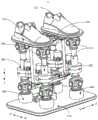
请参阅图1,本发明提供的所述踝关节康复装置1包括基座110、固定组件120以及驱动装置,其中,所述固定组件120包括用于供用户的两脚穿戴的两个穿戴部121,所述穿戴部121活动安装于所述基座110,且分别具有沿左右向轴线前后翻转、沿前后向轴线左右翻转以及沿上下向轴线水平摆动的活动行程;所述驱动装置设于所述基座110,所述驱动装置用以分别驱动所述两个穿戴部121沿左右向轴线前后翻转、沿前后向轴线左右翻转以及沿上下向轴线水平摆动。Please refer to Fig. 1, the ankle
本发明提供的技术方案中,穿戴部121供用户的脚部穿戴,由于用户的的脚部与穿戴部121相对固定,使得在驱动装置的驱动下,当穿戴部121沿左右向轴线前后翻转时,可带动用户的脚部进行背屈训练及跖屈训练;当穿戴部121沿前后向轴线左右翻转时,可带动用户的脚部进行内翻训练及外翻训练;当穿戴部121沿上下向轴线水平摆动时,可带动用户的脚部进行内旋训练及外旋训练,从而有助于丰富踝关节康复装置1的训练形式,提高踝关节康复装置1的实用性。In the technical solution provided by the present invention, the wearing
本设计对所述基座110的具体表现形式不作限制,在不同的应用需求下,所述基座110可以设置为呈箱体状、块状、板状或者由多个支撑板及多个支撑柱共同搭建构成的架体状。在本实施例中,以所述基座110为用于放置于地板上、或者用于安装至训练平台上的板状结构为例。所述基座110相对地板固定,所述固定组件120及所述驱动装置均安装于所述基座110上,从而获得结构紧凑的所述踝关节康复装置1。This design does not limit the specific form of expression of the
所述固定组件120包括两个穿戴部121,所述穿戴部121的具体表现形式不作限制,在一实施例中,所述穿戴部121可简单设置为底座及凸设在底座上的挡环,所述底座用以供脚部放置,所述挡环用以对脚部进行限位;当然,请参阅图1,在本实施例中,所述穿戴部121与鞋子的形状大致相同,能够固定用户的脚部的同时,增加用户穿戴的舒适度;两个所述穿戴部121适于两个脚部的轮廓形状设置,提高穿戴部121与脚部的贴合程度的同时,有助于防呆容错。The fixing
在进一步的实施例中,可设置所述穿戴部121包括穿戴主体与底板,所述底板安装于所述基座110,所述穿戴主体与所述底板可拆卸连接,有助于根据不同的脚部尺寸更换不同尺寸的穿戴主体;或者,可设置所述穿戴主体的长度可调节,例如,设置所述穿戴主体保护两个穿戴单体,两个穿戴单体沿前后向间隔布设,且具有相互靠近和相互远离的活动行程,具体例如,两个穿戴单体中的至少一个滑动连接于底板,通过调节该穿戴单体相对底板的滑动行程,可调节该穿戴单体与另一穿戴单体之间的距离,从而实现整个穿戴主体的长度的调节,提高穿戴部121的适用性。In a further embodiment, the wearing
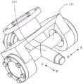
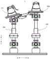
所述驱动装置的具体方案有多种,请参阅图2及图3,在一实施例中,所述驱动装置包括对应两个所述穿戴部121设置的至少两个第一驱动组件200,每一所述第一驱动组件200包括调节部210,所述调节部210包括安装座211以及十字轴212,其中,所述安装座211具有朝向对应的所述穿戴部121设置的安装槽;所述十字轴212具有分别沿前后向及沿左右向延伸设置的两个转动轴213,两个所述转动轴213的中部连接呈一体,两个所述转动轴213的其中一个转动安装于所述安装槽内,另外一个转动安装于对应的所述穿戴部121的底部。There are many specific schemes of the driving device. Please refer to FIG. 2 and FIG. 3. In one embodiment, the driving device includes at least two
可以理解,所述调节部210用于实现所述穿戴部121在前后向、在左右向上的旋转自由度。所述转动轴213与安装座211之间、与所述穿戴部121之间的连接处可设置有滚针轴承,增加转动连接处的转动顺畅。It can be understood that the
在一实施例中,所述安装座211可以沿上下向设置为两个,两个所述安装座211的两个安装槽的槽口相对设置,两个安装槽分别沿前后向、左右向贯通设置,对应使得两个安装槽的左右两侧壁、前后两侧壁可供十字轴212的两个转动轴213分别转动安装;其中一个安装座211的底部与穿戴部121固定连接;所述安装座211的设置,为十字轴212的旋转提供支撑,且便利于调节部210与穿戴部121之间的拆装便利。In one embodiment, the mounting
需要说明,通过对所述安装座211的尺寸的设置,可在一定程度上限制穿戴部121沿前后向、沿左右向的转动角度;或者,可在安装座211对应穿戴部121的转动行程上设置有限位挡筋(附图未标示),所述限位挡筋相对安装座211沿穿戴部121的转动方向活动设置,用于根据实际需要,调节两个转动轴213的最大旋转角度。It should be noted that by setting the size of the mounting
进一步地,在一实施例中,所述调节部210还包括沿上下向延伸设置的伸缩杆214,所述伸缩杆214与所述安装座211连接,用于调节所述安装座211沿上下向活动。所述伸缩杆214能够实现穿戴部121沿上下向的活动,配合十字轴212,更能还原人体的踝关节在内翻、外翻、背屈及跖屈时的复合活动方式。所述伸缩杆214的具体方案有多种,例如,所述伸缩杆214可以是螺母与丝杠的螺纹连接配合、可以是活塞筒与活塞杆的配合、也可以是至少两个摇杆的配合等,此处不作一一赘述。Further, in one embodiment, the
更进一步地,在一实施例中,每一所述第一驱动组件200包括两个所述调节部210、第一驱动器220及第一减速器230,所述两个调节部210沿上下向间隔布设,两个调节部210的设置,能够增加第一驱动组件200的活动自由度,使得用户的踝关节在内翻、外翻、背屈及跖屈时更加灵活自由。所述第一减速器230设于所述两个调节部210之间,所述第一减速器230的输入端与所述第一驱动器220的旋转输出轴连接,所述第一减速器230的输出端设有两个,且与两个所述调节部210的两个所述伸缩杆214分别连接。Furthermore, in one embodiment, each of the
可以理解,所述第一驱动器220可以是电机、回转气缸或者其他能够提供旋转动力的驱动设备。所述第一减速器230用于调节所述第一驱动器220输出的旋转动力,使得该旋转动力作用在调节部210上时,速度更为均衡柔和,避免对用户的踝关节产生二次伤害。两个所述调节部210上下布设,且在两个调节部210中,两个伸缩杆214相较于两个安装座211更靠近设置,便利于两个伸缩杆214与第一减速器230的两个输出端之间的连接。第一驱动器220及第一减速器230设置在两个调节部210的中间,使得同一第一驱动器220可对应控制两个调节部210的独立活动,具有结构紧凑、操作方便的优点。It can be understood that the
接着,在一实施例中,所述第一驱动组件200对应每一所述穿戴部121的前底部和后底部分别设有两个,有助于提高穿戴部121的活动稳定性,且有助于对用户的前脚掌、后脚掌的活动进行分别驱动。此时,每一所述驱动组件包括上下布设的调节部210、第一驱动器220及第一减速器230。Next, in one embodiment, two
具体而言,请参阅4,当穿戴部121的前底部的十字轴212、后底部的十字轴212均朝后翻转,且穿戴部121的前底部的伸缩杆214向上伸长、穿戴部121的后底部的伸缩杆214向下回缩时,可带动用户的脚部进行背屈训练;此时,通过调节例如上述的限位挡筋,可设置所述穿戴部121的旋转角度在20°~30°范围内,更适于用户的背屈康复训练,避免对用户的脚背部产生二次拉伤。Specifically, please refer to 4. When the
请参阅图5,当穿戴部121的前底部的十字轴212、后底部的十字轴212均朝前翻转,且穿戴部121的前底部的伸缩杆214向下回缩、穿戴部121的后底部的伸缩杆214向上伸长时,可带动用户的脚部进行跖屈训练;此时,通过调节例如上述的限位挡筋,可设置所述穿戴部121的旋转角度在40°~50°范围内,更适于用户的跖屈康复训练。Please refer to Fig. 5, when the
请参阅图6,当右侧的穿戴部121朝左翻转,且左侧的穿戴部121的伸缩杆214向下回缩、右侧的穿戴部121的伸缩杆214向上伸长时,可带动用户的右踝关节进行外翻训练;此时,通过调节例如上述的限位挡筋,可设置所述穿戴部121的旋转角度不超过45°。Please refer to Fig. 6, when the wearing
请参阅图7,当左侧的穿戴部121朝右翻转,且左侧的穿戴部121的伸缩杆214向上伸长、右侧的穿戴部121的伸缩杆214向下缩回时,可带动用户的左踝关节进行外翻训练;此时,通过调节例如上述的限位挡筋,可设置所述穿戴部121的旋转角度不超过45°。Please refer to Fig. 7, when the wearing
请参阅图8,当右侧的穿戴部121朝右翻转,且左侧的穿戴部121的伸缩杆214向上伸长、右侧的穿戴部121的伸缩杆214向下回缩时,可带动用户的右踝关节进行内翻训练;此时,通过调节例如上述的限位挡筋,可设置所述穿戴部121的旋转角度不超过45°。Please refer to Fig. 8, when the wearing
请参阅图9,当左侧的穿戴部121朝左翻转,且左侧的穿戴部121的伸缩杆214向下回缩、右侧的穿戴部121的伸缩杆214向上伸长时,可带动用户的左踝关节进行外翻训练;此时,通过调节例如上述的限位挡筋,可设置所述穿戴部121的旋转角度不超过45°。Please refer to Fig. 9, when the wearing
此外,请参阅图10至图11,在一实施例中,所述驱动装置包括第二驱动组件300,所述第二驱动组件300包括第二驱动器320、联动件310以及第二减速器330,其中,所述联动件310与两个所述穿戴部121分别连接;所述第二减速器330的输入端与所述第二驱动器320的旋转输出轴连接,所述当第二减速器330的输出端与所述联动件310连接,以通过所述联动件310,带动两个所述穿戴部121沿上下向轴线同步摆动。与上述同理地,所述第二驱动器320可以是电机、回转气缸或者其他能够提供旋转动力的驱动设备。所述第二减速器330用于调节所述第二驱动器320输出的旋转动力,使得该旋转动力作用在联动件310上时,速度更为均衡柔和,避免对用户的踝关节产生二次伤害。所述联动件310实现两个穿戴部121的同步摆动,有助于提高用户的踝关节进行左旋及右旋时的协调性。In addition, referring to FIG. 10 to FIG. 11 , in an embodiment, the driving device includes a
当然,在其他实施例中,也可设置该联动件310与两个穿戴部121分别可通断连接,使得根据不同的需求,可调节第二驱动器320、第二减速器330通过联动件310与对应的穿戴部121连接,从而控制该穿戴部121所对应的脚部进行左旋或者右旋。Of course, in other embodiments, the
具体而言,在一实施例中,所述联动件310包括两个摆杆311、两个连杆313、第一摇杆314以及第二摇杆315,其中,所述两个摆杆311设于两个所述穿戴部121的下方,且通过两个支撑杆312与两个所述穿戴部121对应连接;所述两个连杆313与两个所述摆杆311的两端分别铰接,以共同围合构成一平行四边形机构,其中一所述连杆313相对所述基座110固定;所述第一摇杆314的一端与所述第二减速器330的输出端连接;所述第二摇杆315的一端与所述第一摇杆314的另一端铰接,所述第二摇杆315的另一端与至少一所述摆杆311铰接。Specifically, in one embodiment, the
具体而言,两个摆杆311及两个连杆313共同围合构成一平行四边形机构;两个摆杆311对应设于两个穿戴部121的下方,两个支撑杆312分别铰接对应的摆杆311及穿戴部121,所述支撑杆312用于提高穿戴部121的活动稳定性。需要说明,由于一连杆313相对基座110固定,所述支撑杆312和摆杆311之间的连接处、与所述摆杆311与该连杆313之间的连接处间隔设置。同样地,所述第二摇杆315和摆杆311之间的连接处、与所述摆杆311与该连杆313之间的连接处间隔设置,以能够将第一摇杆314的旋转驱动力传递至摆杆311处。Specifically, the two
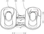
基于上述,请参阅图12,在一实施例中,第二驱动器320的旋转动力依次经第一摇杆314、第二摇杆315传递至摆杆311时,带动摆杆311向左旋转,继而实现穿戴部121的左旋;请参阅图13,在一实施例中,第二驱动器320的方向旋转动力依次经第一摇杆314、第二摇杆315传递至摆杆311时,带动摆杆311向右旋转,继而实现穿戴部121的右旋。Based on the above, please refer to FIG. 12. In one embodiment, when the rotational power of the
此外,请参阅图1,在一实施例中,两个所述穿戴部121的底部通过球笼式万向节400转动安装于所述基座110。所述球笼式万向节400的具体结构可参考现有技术,此处不作详述。当然,所述球笼式万向节400可由其他结构替代,此处不作限制。所述球笼式万向节400的设置,为穿戴部121的左旋及右旋提供足够的活动空间而不至于自锁。具体而言,当如上述实施例,第一驱动组件200包括两个调节部210时,球笼式万向节400设置在位于下方的调节部210的安装座211的底部、与基座110之间。In addition, please refer to FIG. 1 , in one embodiment, the bottoms of the two wearing
请参阅图14至图15,在一实施例中,所述固定组件120还包括设于两个所述穿戴部121之间的弹性铰链500,所述弹性铰链500的左右两端分别铰接两个所述穿戴部121。所述弹性铰链500可设置为整体由弹性材质制成,或者,在一实施例中,所述弹性铰链500包括两个呈剪叉式交叉布设的铰链单体510,两个铰链单体510的两端连接两个穿戴部121,且在铰链单体510与穿戴部121之间的连接处设置有弹簧520,实现两个穿戴部121的弹性铰接;所述弹性铰链500的设置,有助于为两个穿戴部121提供足够的延展拉伸力,且同时具有足够的连接刚度。Please refer to Fig. 14 to Fig. 15. In one embodiment, the fixing
此外,请参阅图2及图10,在一实施例中,,所述踝关节康复装置1还包括传感器以及控制器,其中,所述传感器设于所述驱动装置,用以感测所述穿戴部121的旋转角度和/或力矩;所述控制器与所述传感器、所述驱动装置分别电连接,用以根据所述传感器感测的旋转角度和/或力矩,控制所述驱动装置工作。In addition, please refer to FIG. 2 and FIG. 10 , in one embodiment, the ankle
具体而言,在上述的升降机构中,所述传感器包括设置在两个伸缩杆214之间的力矩传感器610,用以感测两个伸缩杆214之间的力矩变化;所述传感器还可包括设置在穿戴部121的角度传感器620,用于感测穿戴部121的旋转角度变化。控制器根据接收到的力矩值和/或旋转角度,对第一驱动组件200、第二驱动组件300进行分别控制,能够灵活调节穿戴部121的转动行程,便利于根据踝关节的不同受损情况,调整不同的康复治疗方案。Specifically, in the above-mentioned lifting mechanism, the sensor includes a
以上所述仅为本发明的优选实施例,并非因此限制本发明的专利范围,凡是在本发明的发明构思下,利用本发明说明书及附图内容所作的等效结构变换,或直接/间接运用在其他相关的技术领域均包括在本发明的专利保护范围内。The above is only a preferred embodiment of the present invention, and does not therefore limit the patent scope of the present invention. Under the inventive concept of the present invention, the equivalent structural transformation made by using the description of the present invention and the contents of the accompanying drawings, or direct/indirect use All other relevant technical fields are included in the patent protection scope of the present invention.
Claims (3)
Translated fromChinesePriority Applications (1)
| Application Number | Priority Date | Filing Date | Title |
|---|---|---|---|
| CN202011257683.0ACN112353643B (en) | 2020-11-11 | 2020-11-11 | Ankle joint rehabilitation device |
Applications Claiming Priority (1)
| Application Number | Priority Date | Filing Date | Title |
|---|---|---|---|
| CN202011257683.0ACN112353643B (en) | 2020-11-11 | 2020-11-11 | Ankle joint rehabilitation device |
Publications (2)
| Publication Number | Publication Date |
|---|---|
| CN112353643A CN112353643A (en) | 2021-02-12 |
| CN112353643Btrue CN112353643B (en) | 2023-05-23 |
Family
ID=74515332
Family Applications (1)
| Application Number | Title | Priority Date | Filing Date |
|---|---|---|---|
| CN202011257683.0AActiveCN112353643B (en) | 2020-11-11 | 2020-11-11 | Ankle joint rehabilitation device |
Country Status (1)
| Country | Link |
|---|---|
| CN (1) | CN112353643B (en) |
Families Citing this family (1)
| Publication number | Priority date | Publication date | Assignee | Title |
|---|---|---|---|---|
| CN111265352B (en)* | 2020-03-04 | 2021-10-15 | 河南中医药大学第一附属医院 | A bedside adjustable ankle joint rehabilitation correction device |
Citations (8)
| Publication number | Priority date | Publication date | Assignee | Title |
|---|---|---|---|---|
| US6277057B1 (en)* | 2000-02-28 | 2001-08-21 | Craig Hayden | Ankle rehabilitation device |
| JP2008023258A (en)* | 2006-07-25 | 2008-02-07 | Matsushita Electric Works Ltd | Ankle training apparatus |
| CN103190972A (en)* | 2013-04-12 | 2013-07-10 | 郑州轻工业学院 | Auxiliary ankle recovering device with sphere-pin pairs |
| CN204411605U (en)* | 2015-02-10 | 2015-06-24 | 南通大学附属医院 | A kind of ankle-joint device for healing and training |
| CN105125381A (en)* | 2015-10-19 | 2015-12-09 | 吉林大学 | Multi-degree-of-freedom adjustable ankle and knee joint linkage rehabilitative training machine |
| CN105310862A (en)* | 2015-07-26 | 2016-02-10 | 广东铭凯医疗机器人有限公司 | Ankle joint rehabilitation training device |
| US9849328B1 (en)* | 2011-12-19 | 2017-12-26 | Kent Fulks | Method and apparatus for bi-directional ankle exercise movements |
| CN209237264U (en)* | 2018-11-11 | 2019-08-13 | 上海市第一康复医院(上海市杨浦区老年医院) | Removable ankle-joint exoskeleton rehabilitation image training robot |
Family Cites Families (18)
| Publication number | Priority date | Publication date | Assignee | Title |
|---|---|---|---|---|
| TW200838489A (en)* | 2006-09-25 | 2008-10-01 | Matsushita Electric Works Ltd | Passive exercise device |
| US8202239B2 (en)* | 2006-09-25 | 2012-06-19 | Gary Blaine Wilkerson | Ankle derotation and subtalar stabilization orthosis |
| WO2009122559A1 (en)* | 2008-03-31 | 2009-10-08 | パナソニック電工株式会社 | Exercise aiding apparatus |
| US8206267B2 (en)* | 2009-12-04 | 2012-06-26 | Northeastern University | Virtual ankle and balance trainer system |
| JP2013081490A (en)* | 2010-02-23 | 2013-05-09 | Panasonic Corp | Exercise aid |
| CN202277642U (en)* | 2011-10-25 | 2012-06-20 | 胡江勇 | Hand-held body shaping and waist twisting machine |
| CN102499854B (en)* | 2011-11-18 | 2014-04-09 | 上海电机学院 | Parallel structure type ankle joint rehabilitation training device |
| CN105853142B (en)* | 2016-04-08 | 2018-08-31 | 王春宝 | The ankle joint rehabilitation training device of integrated rehabilitation training and motion state detection |
| CN105965484B (en)* | 2016-07-12 | 2018-08-31 | 佛山衡生医疗自动化有限公司 | Robot for rehabilitation of anklebone |
| CN209019345U (en)* | 2018-03-07 | 2019-06-25 | 许昌学院 | A special lower limb training activity device for diabetic patients |
| CN208989573U (en)* | 2018-09-15 | 2019-06-18 | 郑州大学第一附属医院 | A three-degree-of-freedom ankle joint assisted rehabilitation device |
| CN109568086B (en)* | 2019-01-23 | 2024-02-13 | 河南科技大学 | Completely isotropic ankle joint rehabilitation parallel robot |
| CN109875848B (en)* | 2019-04-03 | 2020-12-29 | 曲阜师范大学 | A horizontal lower limb rehabilitation robot training mechanism and system |
| CN109820696B (en)* | 2019-04-09 | 2021-04-13 | 合肥工业大学 | Ankle rehabilitation mechanism based on human body correlation drive |
| CN210472942U (en)* | 2019-08-26 | 2020-05-08 | 张剑剑 | Lower limb exercising rehabilitation device |
| CN110711109B (en)* | 2019-09-24 | 2021-02-09 | 燕山大学 | Metamorphic parallel mechanism suitable for ankle joint rehabilitation |
| CN111202656A (en)* | 2020-01-20 | 2020-05-29 | 东北大学秦皇岛分校 | A rope-driven parallel ankle joint rehabilitation device |
| CN111759680A (en)* | 2020-08-06 | 2020-10-13 | 马鞍山学院 | Robot for training human ankle joint |
- 2020
- 2020-11-11CNCN202011257683.0Apatent/CN112353643B/enactiveActive
Patent Citations (8)
| Publication number | Priority date | Publication date | Assignee | Title |
|---|---|---|---|---|
| US6277057B1 (en)* | 2000-02-28 | 2001-08-21 | Craig Hayden | Ankle rehabilitation device |
| JP2008023258A (en)* | 2006-07-25 | 2008-02-07 | Matsushita Electric Works Ltd | Ankle training apparatus |
| US9849328B1 (en)* | 2011-12-19 | 2017-12-26 | Kent Fulks | Method and apparatus for bi-directional ankle exercise movements |
| CN103190972A (en)* | 2013-04-12 | 2013-07-10 | 郑州轻工业学院 | Auxiliary ankle recovering device with sphere-pin pairs |
| CN204411605U (en)* | 2015-02-10 | 2015-06-24 | 南通大学附属医院 | A kind of ankle-joint device for healing and training |
| CN105310862A (en)* | 2015-07-26 | 2016-02-10 | 广东铭凯医疗机器人有限公司 | Ankle joint rehabilitation training device |
| CN105125381A (en)* | 2015-10-19 | 2015-12-09 | 吉林大学 | Multi-degree-of-freedom adjustable ankle and knee joint linkage rehabilitative training machine |
| CN209237264U (en)* | 2018-11-11 | 2019-08-13 | 上海市第一康复医院(上海市杨浦区老年医院) | Removable ankle-joint exoskeleton rehabilitation image training robot |
Also Published As
| Publication number | Publication date |
|---|---|
| CN112353643A (en) | 2021-02-12 |
Similar Documents
| Publication | Publication Date | Title |
|---|---|---|
| CN103054692B (en) | Wearable lower limb exoskeleton walking-assisted robot | |
| CN103622796B (en) | A kind of wearable lower limb device for healing and training | |
| CN203060231U (en) | Wearable lower limb exoskeleton walking-assisting robot | |
| CN103961240B (en) | Ankle foot healing training devices and balance training system | |
| JP6647225B2 (en) | Leg straightening device and straightening device | |
| CN110465924A (en) | A kind of lower limb exoskeleton robot of four bar linkage knee joint | |
| CN108245372A (en) | The Three Degree Of Freedom ankle healing robot of pneumatic muscles combination Wire driven robot | |
| KR101619745B1 (en) | Ankle exercise apparatus | |
| CN106901947A (en) | Wearable lower extremity exoskeleton assisted walking robot mechanism | |
| CN209203951U (en) | Guiding mechanism, lower limb rehabilitation ectoskeleton and exoskeleton robot | |
| CN105167965A (en) | Linkage type walking-aiding rehabilitation robot with joint rotation center taken into consideration | |
| CN108553271A (en) | A kind of MR damper sitting and lying formula lower limb rehabilitation robot | |
| TW200934553A (en) | Standing-position type passive exercise machine | |
| CN108904225A (en) | Step device and walking rehabilitation training robot | |
| CN215021755U (en) | Wearable exoskeleton hip joint rehabilitation robot | |
| CN106726342A (en) | Pliability trainer | |
| CN106236508A (en) | One crouches, sits, stands the three healthy training devicess of attitude lower limb | |
| CN108969296A (en) | A kind of lower limb rehabilitation robot | |
| CN206261792U (en) | A kind of healthy plint of multi-pose lower limb | |
| CN109124990A (en) | Lower limb rehabilitation ectoskeleton and exoskeleton robot | |
| KR101230458B1 (en) | Rehabilitation machine device for knee joint | |
| CN109124988A (en) | Guiding mechanism, lower limb rehabilitation ectoskeleton and exoskeleton robot | |
| CN202426827U (en) | Ankle correction device and ankle rehabilitation device using same | |
| CN108245373B (en) | Ankle joint rehabilitation device with six crossed rotary joint axes | |
| CN112353643B (en) | Ankle joint rehabilitation device |
Legal Events
| Date | Code | Title | Description |
|---|---|---|---|
| PB01 | Publication | ||
| PB01 | Publication | ||
| SE01 | Entry into force of request for substantive examination | ||
| SE01 | Entry into force of request for substantive examination | ||
| GR01 | Patent grant | ||
| GR01 | Patent grant |