CN112345927B - Fuse monitoring system and intelligent fuse - Google Patents
Fuse monitoring system and intelligent fuseDownload PDFInfo
- Publication number
- CN112345927B CN112345927BCN202010844636.XACN202010844636ACN112345927BCN 112345927 BCN112345927 BCN 112345927BCN 202010844636 ACN202010844636 ACN 202010844636ACN 112345927 BCN112345927 BCN 112345927B
- Authority
- CN
- China
- Prior art keywords
- fuse
- electric field
- diode
- module
- monitoring base
- Prior art date
- Legal status (The legal status is an assumption and is not a legal conclusion. Google has not performed a legal analysis and makes no representation as to the accuracy of the status listed.)
- Active
Links
Images


Classifications
- G—PHYSICS
- G01—MEASURING; TESTING
- G01R—MEASURING ELECTRIC VARIABLES; MEASURING MAGNETIC VARIABLES
- G01R31/00—Arrangements for testing electric properties; Arrangements for locating electric faults; Arrangements for electrical testing characterised by what is being tested not provided for elsewhere
- G01R31/327—Testing of circuit interrupters, switches or circuit-breakers
- G—PHYSICS
- G01—MEASURING; TESTING
- G01R—MEASURING ELECTRIC VARIABLES; MEASURING MAGNETIC VARIABLES
- G01R19/00—Arrangements for measuring currents or voltages or for indicating presence or sign thereof
- G01R19/165—Indicating that current or voltage is either above or below a predetermined value or within or outside a predetermined range of values
- H—ELECTRICITY
- H02—GENERATION; CONVERSION OR DISTRIBUTION OF ELECTRIC POWER
- H02J—CIRCUIT ARRANGEMENTS OR SYSTEMS FOR SUPPLYING OR DISTRIBUTING ELECTRIC POWER; SYSTEMS FOR STORING ELECTRIC ENERGY
- H02J13/00—Circuit arrangements for providing remote indication of network conditions, e.g. an instantaneous record of the open or closed condition of each circuitbreaker in the network; Circuit arrangements for providing remote control of switching means in a power distribution network, e.g. switching in and out of current consumers by using a pulse code signal carried by the network
- H02J13/00006—Circuit arrangements for providing remote indication of network conditions, e.g. an instantaneous record of the open or closed condition of each circuitbreaker in the network; Circuit arrangements for providing remote control of switching means in a power distribution network, e.g. switching in and out of current consumers by using a pulse code signal carried by the network characterised by information or instructions transport means between the monitoring, controlling or managing units and monitored, controlled or operated power network element or electrical equipment
- H02J13/00022—Circuit arrangements for providing remote indication of network conditions, e.g. an instantaneous record of the open or closed condition of each circuitbreaker in the network; Circuit arrangements for providing remote control of switching means in a power distribution network, e.g. switching in and out of current consumers by using a pulse code signal carried by the network characterised by information or instructions transport means between the monitoring, controlling or managing units and monitored, controlled or operated power network element or electrical equipment using wireless data transmission
- Y—GENERAL TAGGING OF NEW TECHNOLOGICAL DEVELOPMENTS; GENERAL TAGGING OF CROSS-SECTIONAL TECHNOLOGIES SPANNING OVER SEVERAL SECTIONS OF THE IPC; TECHNICAL SUBJECTS COVERED BY FORMER USPC CROSS-REFERENCE ART COLLECTIONS [XRACs] AND DIGESTS
- Y02—TECHNOLOGIES OR APPLICATIONS FOR MITIGATION OR ADAPTATION AGAINST CLIMATE CHANGE
- Y02E—REDUCTION OF GREENHOUSE GAS [GHG] EMISSIONS, RELATED TO ENERGY GENERATION, TRANSMISSION OR DISTRIBUTION
- Y02E60/00—Enabling technologies; Technologies with a potential or indirect contribution to GHG emissions mitigation
- Y—GENERAL TAGGING OF NEW TECHNOLOGICAL DEVELOPMENTS; GENERAL TAGGING OF CROSS-SECTIONAL TECHNOLOGIES SPANNING OVER SEVERAL SECTIONS OF THE IPC; TECHNICAL SUBJECTS COVERED BY FORMER USPC CROSS-REFERENCE ART COLLECTIONS [XRACs] AND DIGESTS
- Y04—INFORMATION OR COMMUNICATION TECHNOLOGIES HAVING AN IMPACT ON OTHER TECHNOLOGY AREAS
- Y04S—SYSTEMS INTEGRATING TECHNOLOGIES RELATED TO POWER NETWORK OPERATION, COMMUNICATION OR INFORMATION TECHNOLOGIES FOR IMPROVING THE ELECTRICAL POWER GENERATION, TRANSMISSION, DISTRIBUTION, MANAGEMENT OR USAGE, i.e. SMART GRIDS
- Y04S40/00—Systems for electrical power generation, transmission, distribution or end-user application management characterised by the use of communication or information technologies, or communication or information technology specific aspects supporting them
- Y04S40/12—Systems for electrical power generation, transmission, distribution or end-user application management characterised by the use of communication or information technologies, or communication or information technology specific aspects supporting them characterised by data transport means between the monitoring, controlling or managing units and monitored, controlled or operated electrical equipment
- Y04S40/126—Systems for electrical power generation, transmission, distribution or end-user application management characterised by the use of communication or information technologies, or communication or information technology specific aspects supporting them characterised by data transport means between the monitoring, controlling or managing units and monitored, controlled or operated electrical equipment using wireless data transmission
Landscapes
- Physics & Mathematics (AREA)
- General Physics & Mathematics (AREA)
- Engineering & Computer Science (AREA)
- Computer Networks & Wireless Communication (AREA)
- Power Engineering (AREA)
- Emergency Protection Circuit Devices (AREA)
Abstract
Description
Translated fromChinese技术领域technical field
本发明涉及电网监测技术领域,特别是指一种熔断器的监测系统及智能型熔断器。The invention relates to the technical field of power grid monitoring, in particular to a fuse monitoring system and an intelligent fuse.
背景技术Background technique
在我国配网线路中,熔断器得到广泛使用,其原理主要依靠所选择的不同额度电流的熔丝来限定线路电流,当发生大电流故障时,电流超过熔丝额定电流,熔体自身熔断形成电弧,然后电弧在高温作用下,将灭弧管内的特殊材料气化产生大量气体,再依靠此气体在电流过零时将电弧吹灭,并通过弹簧作用将载熔管推出熔断器本体外,形成电气端口,切断故障,实现对配网线路的保护。现在面临的难题在于较难对熔断器自身运行状态及线路运行状态有准确的判断,故障定位困难。In my country's distribution network lines, fuses are widely used. The principle mainly depends on the selected fuses with different rated currents to limit the line current. When a large current fault occurs, the current exceeds the rated current of the fuse, and the melt itself fuses to form Arc, and then under the action of high temperature, the arc will vaporize the special material in the arc extinguishing tube to produce a large amount of gas, and then rely on this gas to blow out the arc when the current crosses zero, and push the fuse tube out of the fuse body through the action of a spring. Form an electrical port, cut off the fault, and realize the protection of the distribution network line. The problem now is that it is difficult to accurately judge the operating status of the fuse itself and the operating status of the line, and it is difficult to locate the fault.
现阶段有很多熔断器载熔管状态监测方法,例如利用重力感应方式监测、利用位移传感器监测的方法等。其中,利用重力感应方式的监测方法为,当熔断器载熔管弹出时,通过重力感应检测电路检测到载熔管跌落,载熔管跌落时触发电路将单片机唤醒,单片机被唤醒后对采集状态数据信息进行处理,确定熔丝熔断。然而,该方法需额外在熔断器底座上打孔安装传感器,使结构复杂,影响外观且不易安装。At this stage, there are many methods for monitoring the state of fuse-carrying tubes, such as monitoring by gravity sensing and monitoring by displacement sensors. Among them, the monitoring method using the gravity sensing method is that when the fuse carrying tube pops up, the gravity sensing detection circuit detects that the carrying tube has fallen, and when the melting tube falls, the trigger circuit wakes up the single-chip microcomputer. After the single-chip is awakened, the acquisition status The data information is processed to determine that the fuse is blown. However, this method needs to drill additional holes on the fuse base to install the sensor, which makes the structure complicated, affects the appearance and is not easy to install.
利用位移传感器监测的方法为,在熔断器本体上设置有位置监测部件,监测部件的位置与载熔管在熔断器本体的位置对应,该监测部件通过载熔管位置的变化判断熔丝的通断状态。然而,该方法只能对熔断器熔丝状态进行监测,但配网线路是否存在其他状态,如停电等情况无法判别。The method of using the displacement sensor to monitor is that a position monitoring component is installed on the fuse body, and the position of the monitoring component corresponds to the position of the fuse-carrying tube on the fuse body. off state. However, this method can only monitor the fuse state of the fuse, but it cannot be judged whether there are other states in the distribution network line, such as power failure.
发明内容Contents of the invention
有鉴于此,本发明的目的在于提出一种熔断器的监测系统及智能型熔断器,结构简单、不影响外观、易于安装,且不仅可以对熔断器熔丝状态进行监测,还可以对线路的电流、电场值进行监测并判断是否存在其它,如停电等情况。In view of this, the object of the present invention is to propose a fuse monitoring system and an intelligent fuse, which has a simple structure, does not affect the appearance, is easy to install, and can not only monitor the state of the fuse, but also monitor the Monitor the current and electric field values and judge whether there are other conditions, such as power failure.
基于上述目的,本发明提供一种熔断器的监测系统,用于对设置于三相线路上的熔断器进行监测,所述系统包括:Based on the above purpose, the present invention provides a fuse monitoring system for monitoring fuses installed on three-phase lines. The system includes:
设置于所述熔断器底部的智能监测底座、套于所述熔断器的下引线处的 CT环、以及管理终端;其中,所述智能监测底座中包括:PCB板、焊接于 PCB板上的电路元件,以及铺覆于所述PCB板上、下表面的一对铜箔;所述 CT环中包括电流测量传感器;所述焊接于PCB板上的电路元件包括:电场测量模块、第一放大器、MCU、第二放大器、无线模块;The intelligent monitoring base arranged at the bottom of the fuse, the CT ring set on the lower lead of the fuse, and the management terminal; wherein, the intelligent monitoring base includes: a PCB board, a circuit welded on the PCB board Components, and a pair of copper foils covered on the PCB board and the lower surface; the CT ring includes a current measurement sensor; the circuit components welded on the PCB include: an electric field measurement module, a first amplifier, MCU, second amplifier, wireless module;
其中,所述电场测量模块用于对所述铜箔形成的电势差进行测量,将测量的电场值输出到第一放大器;经第一放大器放大的信号输入到所述MCU;Wherein, the electric field measurement module is used to measure the potential difference formed by the copper foil, and output the measured electric field value to the first amplifier; the signal amplified by the first amplifier is input to the MCU;
所述电流测量传感器用于测量所述熔断器所在线路的电流,并将测量的电流值输出到第二放大器;经第二放大器放大的信号输入到所述MCU;The current measurement sensor is used to measure the current of the circuit where the fuse is located, and output the measured current value to the second amplifier; the signal amplified by the second amplifier is input to the MCU;
所述MCU将测量的电流值、电场值通过所述无线模块上报所述管理终端;所述管理终端根据上报的电流值、电场值判断出熔断器熔丝熔断,或所述熔断器所在线路出现停电的故障。The MCU reports the measured current value and electric field value to the management terminal through the wireless module; the management terminal judges that the fuse is blown according to the reported current value and electric field value, or the line where the fuse is located is broken. Power outage failure.
较佳地,所述管理终端具体用于若三相线路中一相线路的熔断器的智能监测底座上报的电流值低于设定的电流阈值、电场值不低于设定的电场阈值、且当前上报的电场值相较于之前上报的电场值的下降幅度大于设定的幅度阈值,而其它两个熔断器的智能监测底座上报的电流值、电场值均正常,则判断该相线路的熔断器中熔丝熔断,载熔管弹出;若三相线路的三个熔断器的智能监测底座上报的电流值均低于设定的电流阈值、电场值均低于设定的电场阈值、且当前上报的电场值相较于之前上报的电场值的下降幅度均大于设定的幅度阈值,则判断所述三相线路出现停电故障。Preferably, the management terminal is specifically used for if the current value reported by the intelligent monitoring base of the fuse of one phase line in the three-phase line is lower than the set current threshold, the electric field value is not lower than the set electric field threshold, and Compared with the previously reported electric field value, the decrease of the current reported electric field value is greater than the set amplitude threshold, and the current value and electric field value reported by the intelligent monitoring base of the other two fuses are normal, then it is judged that the phase line is blown The fuse in the fuse is blown, and the fuse-carrying tube pops out; if the current values reported by the intelligent monitoring base of the three fuses of the three-phase line are all lower than the set current threshold value, the electric field value is lower than the set electric field threshold value, and the current If the reported electric field values are all lower than the previously reported electric field values by more than the set amplitude threshold, it is determined that the three-phase line has a power outage fault.
较佳地,所述CT环还包括:感应取电传感器;所述焊接于PCB板上的电路元件还包括:升压模块;Preferably, the CT ring also includes: an inductive power-taking sensor; the circuit element welded on the PCB board also includes: a booster module;
其中,所述感应取电传感器从交变电场中取电后输出,经所述升压模块升压;所述升压模块输出升压后的电压,为所述智能监测底座中各电路元件进行供电。Wherein, the inductive power-taking sensor takes power from the alternating electric field and then outputs it, which is boosted by the booster module; the boosted voltage output by the booster module is used for each circuit element in the intelligent monitoring base. powered by.
或者,所述CT环还包括:感应取电传感器;所述焊接于PCB板上的电路元件还包括:超级电容、二极管D1、升压模块、二极管D2、充电管理模块;Alternatively, the CT ring further includes: an inductive power-taking sensor; the circuit elements welded on the PCB further include: a supercapacitor, a diode D1, a boost module, a diode D2, and a charging management module;
其中,所述感应取电传感器通过所述充电管理模块为所述超级电容充电;Wherein, the inductive power-taking sensor charges the supercapacitor through the charging management module;
二极管D1的阳极与所述感应取电传感器的输出相连,二极管D1的阴极与所述升压模块的输入相连;The anode of the diode D1 is connected to the output of the inductive power-taking sensor, and the cathode of the diode D1 is connected to the input of the boost module;
二极管D2的阳极与所述超级电容的电压输出端相连,二极管D2的阴极与所述升压模块的输入相连;The anode of the diode D2 is connected to the voltage output terminal of the supercapacitor, and the cathode of the diode D2 is connected to the input of the boost module;
所述升压模块的输出与所述智能监测底座中各电路元件的电源线相连,为各电路元件进行供电。The output of the step-up module is connected with the power lines of each circuit element in the intelligent monitoring base to supply power for each circuit element.
较佳地,所述感应取电传感器、超级电容、备用电池的输出均与所述 MCU连接;以及Preferably, the outputs of the inductive power-taking sensor, the supercapacitor, and the backup battery are all connected to the MCU; and
所述MCU还用于周期性地将采集的感应取电传感器、超级电容,以及备用电池的输出电压通过所述无线模块上报所述管理终端。The MCU is also configured to periodically report the collected output voltages of the inductive power-taking sensor, the supercapacitor, and the backup battery to the management terminal through the wireless module.
较佳地,所述管理终端还用于在确认智能监测底座上报的感应取电传感器、超级电容,以及备用电池的输出电压均低于设定的电压阈值后,判断该智能监测底座出现低电量事件。Preferably, the management terminal is also used to determine that the intelligent monitoring base has a low battery after confirming that the output voltages of the inductive power-taking sensor, the supercapacitor, and the backup battery reported by the intelligent monitoring base are all lower than the set voltage threshold event.
较佳地,所述管理终端还用于连续三个周期未接收到智能监测底座上报的数据,且不存在低电量事件,则判断该智能监测底座出现通信故障。Preferably, the management terminal is further configured to determine that the intelligent monitoring base has a communication failure if it does not receive the data reported by the intelligent monitoring base for three consecutive periods and there is no low battery event.
进一步,所述系统还包括:系统主站;Further, the system also includes: a system master station;
所述管理终端还用于将根据所述智能监测底座上报的数据作出的判断结果上传至所述系统主站。The management terminal is also used to upload the judgment result made according to the data reported by the intelligent monitoring base to the system master station.
本发明还提供一种智能型熔断器,包括:熔断器本体以及、如上所述系统中的智能监测底座以及CT环。The present invention also provides an intelligent fuse, including: a fuse body, an intelligent monitoring base and a CT ring in the system as described above.
本发明的技术方案的熔断器的监测系统中,包括设置于熔断器底部的智能监测底座、套于所述熔断器的下引线处的CT环、以及管理终端;其中,所述智能监测底座中包括:PCB板、焊接于PCB板上的电路元件,以及铺覆于所述PCB板上、下表面的一对铜箔;所述CT环中包括电流测量传感器;所述焊接于PCB板上的电路元件包括:电场测量模块、第一放大器、MCU、第二放大器、无线模块;其中,所述电场测量模块用于对所述铜箔形成的电势差进行测量,将测量的电场值输出到第一放大器;经第一放大器放大的信号输入到所述MCU;所述电流测量传感器用于测量所述熔断器所在线路的电流,并将测量的电流值输出到第二放大器;经第二放大器放大的信号输入到所述MCU;所述MCU将测量的电流值、电场值通过所述无线模块上报所述管理终端;所述管理终端根据上报的电流值、电场值判断所述熔断器熔丝熔断,或所述熔断器所在线路出现停电故障。由于只需在熔断器底部安装智能监测底座、在熔断器的下引线处套上CT环,结构简单、不影响外观、易于安装,且不仅可以对熔断器熔丝状态进行监测,还可以对线路的电流、电场值进行监测并判断是否存在其它,如停电等情况。The fuse monitoring system of the technical solution of the present invention includes an intelligent monitoring base arranged at the bottom of the fuse, a CT ring set at the lower lead of the fuse, and a management terminal; wherein, the intelligent monitoring base It includes: a PCB board, circuit elements welded on the PCB board, and a pair of copper foils covered on the PCB board and the lower surface; the CT ring includes a current measurement sensor; the soldered on the PCB board The circuit components include: an electric field measurement module, a first amplifier, an MCU, a second amplifier, and a wireless module; wherein, the electric field measurement module is used to measure the potential difference formed by the copper foil, and output the measured electric field value to the first Amplifier; the signal amplified by the first amplifier is input to the MCU; the current measurement sensor is used to measure the current of the line where the fuse is located, and the measured current value is output to the second amplifier; the amplified signal of the second amplifier The signal is input to the MCU; the MCU reports the measured current value and electric field value to the management terminal through the wireless module; the management terminal judges that the fuse of the fuse is blown according to the reported current value and electric field value, Or a power failure occurs on the line where the fuse is located. Since it is only necessary to install an intelligent monitoring base at the bottom of the fuse and put a CT ring on the lower lead of the fuse, the structure is simple, does not affect the appearance, and is easy to install. Not only can the state of the fuse be monitored, but also the circuit Monitor current and electric field values and judge whether there are other conditions, such as power failure.
附图说明Description of drawings
为了更清楚地说明本发明实施例或现有技术中的技术方案,下面将对实施例或现有技术描述中所需要使用的附图作简单地介绍,显而易见地,下面描述中的附图仅仅是本发明的一些实施例,对于本领域普通技术人员来讲,在不付出创造性劳动的前提下,还可以根据这些附图获得其他的附图。In order to more clearly illustrate the technical solutions in the embodiments of the present invention or the prior art, the following will briefly introduce the drawings that need to be used in the description of the embodiments or the prior art. Obviously, the accompanying drawings in the following description are only These are some embodiments of the present invention. Those skilled in the art can also obtain other drawings based on these drawings without creative work.
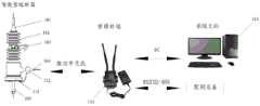
图1为本发明提供的一种熔断器的监测系统的架构示意图;FIG. 1 is a schematic structural diagram of a monitoring system for a fuse provided by the present invention;
图2a、2b分别为本发明提供的熔断器中载熔管未弹出、载熔管弹出状态示意图;Figures 2a and 2b are respectively schematic diagrams of states where the melt-carrying tube is not ejected and the melt-carrying tube is popping up in the fuse provided by the present invention;
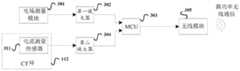
图3为本发明提供的一种智能监测底座中的电路元件连接示意图;Fig. 3 is a schematic diagram of connection of circuit elements in an intelligent monitoring base provided by the present invention;
图4为本发明提供的一种CT环与智能监测底座间的连接示意图;Fig. 4 is a schematic diagram of the connection between a CT ring and an intelligent monitoring base provided by the present invention;
图5a、5b、5c分别为本发明提供的三种实施例的智能监测底座中的电路元件连接示意图。Figures 5a, 5b and 5c are respectively schematic diagrams of connection of circuit elements in the intelligent monitoring base of the three embodiments provided by the present invention.
具体实施方式Detailed ways
为使本发明的目的、技术方案和优点更加清楚明白,以下结合具体实施例,并参照附图,对本发明进一步详细说明。In order to make the object, technical solution and advantages of the present invention clearer, the present invention will be described in further detail below in conjunction with specific embodiments and with reference to the accompanying drawings.
需要说明的是,除非另外定义,本发明实施例使用的技术术语或者科学术语应当为本公开所属领域内具有一般技能的人士所理解的通常意义。本公开中使用的“第一”、“第二”以及类似的词语并不表示任何顺序、数量或者重要性,而只是用来区分不同的组成部分。“包括”或者“包含”等类似的词语意指出现该词前面的元件或者物件涵盖出现在该词后面列举的元件或者物件及其等同,而不排除其他元件或者物件。“连接”或者“相连”等类似的词语并非限定于物理的或者机械的连接,而是可以包括电性的连接,不管是直接的还是间接的。“上”、“下”、“左”、“右”等仅用于表示相对位置关系,当被描述对象的绝对位置改变后,则该相对位置关系也可能相应地改变。It should be noted that, unless otherwise defined, the technical terms or scientific terms used in the embodiments of the present invention shall have the usual meanings understood by those skilled in the art to which the present disclosure belongs. "First", "second" and similar words used in the present disclosure do not indicate any order, quantity or importance, but are only used to distinguish different components. "Comprising" or "comprising" and similar words mean that the elements or items appearing before the word include the elements or items listed after the word and their equivalents, without excluding other elements or items. Words such as "connected" or "connected" are not limited to physical or mechanical connections, but may include electrical connections, whether direct or indirect. "Up", "Down", "Left", "Right" and so on are only used to indicate the relative positional relationship. When the absolute position of the described object changes, the relative positional relationship may also change accordingly.
下面结合附图详细说明本发明的技术方案。The technical solution of the present invention will be described in detail below in conjunction with the accompanying drawings.
本发明提供的一种熔断器的监测系统,用于对设置于三相线路上的三个熔断器进行监测,其架构如图1所示,包括:对于每个熔断器设置于所述熔断器的底部的智能监测底座111、套于所述熔断器的下引线处的环状的CT (电流互感)环112,以及与每个熔断器的智能监测底座111进行无线通信的管理终端113。A fuse monitoring system provided by the present invention is used to monitor three fuses arranged on a three-phase line, and its architecture is shown in Figure 1, including: The
其中,图1中的熔断器(或称熔断器本体)与现有的熔断器结构一致,具体可以包括:上引线101、封闭瓷体102、安装抱箍103、下引线104、载熔管105。载熔管105未弹出的状态,即正常状态,如图2a所示;Wherein, the fuse (or called fuse body) in Fig. 1 is consistent with the existing fuse structure, specifically may include:
安装于熔断器底部的智能监测底座111,中间设有过孔,以便载熔管105 可以通过该过孔弹出;载熔管105弹出的状态,如图2b所示。The
智能监测底座111中包括:PCB板、焊接于PCB板上的电路元件,以及铺覆于所述PCB板上、下表面、形状一致位置相对的一对铜箔。The
熔断器所在线路的周围存在交变电场,所述铜箔作电容用,此电容位于电场内,形成电势差。所述铜箔的位置位于下引线104的正下方,以确保监测到的电场值最大。There is an alternating electric field around the circuit where the fuse is located, and the copper foil is used as a capacitor, and the capacitor is located in the electric field to form a potential difference. The position of the copper foil is directly below the
如图3所示,智能监测底座111中、焊接于PCB板上的电路元件包括:电场测量模块301、第一放大器302、MCU303、第二放大器304、无线模块 305。As shown in FIG. 3 , the circuit elements soldered on the PCB in the
其中,电场测量模块301的输入连接于所述铜箔,电场测量模块301的输出与第一放大器302的输入相连,第一放大器302的输出与MCU303的输入相连;Wherein, the input of the electric
电场测量模块301用于对所述铜箔形成的电势差进行测量,通过检测电势差的大小来表征得到电场值;电场测量模块301将测量的电场值输出到第一放大器302;经第一放大器302放大的信号输入到MCU303,从而MCU303 获得测量的电场值。The electric
CT环112中包括:电流测量传感器311;The
CT环112中的电流测量传感器311的输出接入到智能监测底座111中,如图4所示;The output of the
具体地,电流测量传感器311的输出与智能监测底座111中的第二放大器304的输入相连,第二放大器304的输出与MCU303的输入相连;Specifically, the output of the
电流测量传感器311将线路中的大电流转换为一定比例的小电流输出,实现所述熔断器所在线路的电流的实时测量;电流测量传感器311将测量的电流值输出到第二放大器304;经第二放大器304放大的信号放大输入到 MCU303,从而MCU303获得测量的电流值。The
无线模块305与MCU303相连,MCU303将监测的电流值、电场值通过无线模块305,以无线通信的方式上报管理终端113。具体地,MCU303 可以是周期性地将监测的电流值、电场值、通过无线模块305上报管理终端 113。The
管理终端113通过智能监测底座111上报的电流、电场值可以判断出所述熔断器熔丝熔断的情况,或所述熔断器所在线路出现停电故障的情况:The
若三相线路中一相线路的熔断器的智能监测底座111上报的电流值低于设定的电流阈值、电场值不低于设定的电场阈值、且当前上报的电场值相较于之前上报的电场值的下降幅度大于设定的幅度阈值,而其它两个熔断器的智能监测底座上报的电流值、电场值均正常,则管理终端113判断该相线路的熔断器中熔丝熔断,载熔管弹出;其中,电流值正常的情况具体指的是电流值不低于设定的电流阈值的情况;电场值正常的情况具体指的是电场值不低于设定的电场阈值,且当前上报的电场值相较于之前上报的电场值的下降幅度不大于设定的幅度阈值的情况。If the current value reported by the
若三相线路的三个熔断器的智能监测底座上报的电流值均低于设定的电流阈值、电场值均低于设定的电场阈值、且当前上报的电场值相较于之前上报的电场值的下降幅度均大于设定的幅度阈值,则管理终端113判断所述三相线路出现停电故障。If the current values reported by the intelligent monitoring base of the three fuses of the three-phase line are all lower than the set current threshold, the electric field values are all lower than the set electric field threshold, and the current reported electric field value is higher than the previously reported electric field value. If the drop ranges of the values are greater than the set range threshold, the
对智能监测底座111中焊接于PCB板上的电路元件进行供电的方案,本发明提供了以下三个实施例:For the scheme of supplying power to the circuit elements welded on the PCB board in the
实施例一Embodiment one
在如图3所示的电路结构基础上,还可包括其它电路元件,如图5a所示;其中,CT环112中还可包括:感应取电传感器312;智能监测底座111 中焊接于PCB板上的电路元件还可包括:升压模块308。On the basis of the circuit structure shown in Figure 3, other circuit elements can also be included, as shown in Figure 5a; wherein, the
其中,CT环112中感应取电传感器312的输出接入到智能监测底座111 中,如图1所示;具体地,感应取电传感器312的输出与升压模块308的输 入相连;升压模块308的输出与智能监测底座111中各电路元件的电源线相 连;Wherein, the output of the inductive power-taking sensor 312 in the
感应取电传感器312从交变电场中取电后输出,经升压模块308升压后,升压模块308输出升压后的电压,为智能监测底座111中各电路元件进行供电。The inductive power-taking sensor 312 takes power from the alternating electric field and then outputs it. After the
实施例二Embodiment two
在如图3所示的电路结构基础上,还可包括其它电路元件,如图5b所示;其中,CT环112中还可包括:感应取电传感器312;智能监测底座111 中焊接于PCB板上的电路元件还可包括:超级电容306、二极管D1、升压模块318、二极管D2、充电管理模块309。On the basis of the circuit structure shown in Figure 3, other circuit elements can also be included, as shown in Figure 5b; wherein, the
其中,感应取电传感器312通过充电管理模块309为超级电容306充电;Wherein, the inductive power-taking sensor 312 charges the
二极管D1的阳极与所述感应取电传感器312的输出相连,二极管D1 的阴极与升压模块318的输入相连;The anode of the diode D1 is connected to the output of the inductive power-taking sensor 312, and the cathode of the diode D1 is connected to the input of the
二极管D2的阳极与超级电容306的电压输出端相连,二极管D2的阴极与所述升压模块318的输入相连;The anode of the diode D2 is connected to the voltage output terminal of the
升压模块318的输出与所述智能监测底座中各电路元件的电源线相连,为各电路元件进行供电。The output of the
实施例三Embodiment three
在如图3所示的电路结构基础上,还可包括其它电路元件,如图5c所示;其中,CT环112中还可包括:感应取电传感器312;智能监测底座111 中焊接于PCB板上的电路元件还可包括:超级电容306、二极管D1、二极管D2、充电管理模块、升压模块328、备用电池307、二极管D3、二极管 D4。On the basis of the circuit structure shown in Figure 3, other circuit elements can also be included, as shown in Figure 5c; wherein, the
其中,感应取电传感器312通过充电管理模块309为超级电容306充电;Wherein, the inductive power-taking sensor 312 charges the
二极管D1的阳极与感应取电传感器312的输出相连,二极管D1的阴极与升压模块328的输入相连;The anode of the diode D1 is connected to the output of the inductive power-taking sensor 312, and the cathode of the diode D1 is connected to the input of the
二极管D2的阳极与超级电容306的电压输出端相连,二极管D2的阴极与升压模块328的输入相连;The anode of the diode D2 is connected to the voltage output terminal of the
二极管D3的阳极与所述备用电池307的输出相连,二极管D4的阳极与升压模块328的输出相连;二极管D3、D4的阴极与所述智能监测底座中各电路元件的电源线相连,为各电路元件进行供电。The anode of the diode D3 is connected to the output of the
此外,感应取电传感器312、超级电容306,以及备用电池307的输出还可连接于MCU303,MCU303对感应取电传感器312、超级电容306,以及备用电池307输出的电压进行采集,MCU303也可根据当下熔断器的运行方式选择合适的供电方式;MCU303还可周期性地将采集的感应取电传感器 312、超级电容306,以及备用电池307的输出电压通过无线模块305上报管理终端113。In addition, the output of the inductive power-taking sensor 312, the
进一步,管理终端113还可通过智能监测底座111上报的电压值判别如下异常或故障:Furthermore, the
管理终端113若确认出一个智能监测底座上报的感应取电传感器、超级电容,以及备用电池的输出电压均低于设定的电压阈值,则判断该智能监测底座出现低电量事件,不足以支撑智能监测底座111工作。If the
若管理终端113连续三个周期未接收到智能监测底座111上报的数据,且不存在低电量事件,即之前上报的感应取电传感器312、超级电容306,以及备用电池307的输出电压中至少有一个电压大于等于电压阈值,则判定该智能监测底座111出现通信故障。If the
进一步,本发明提供的一种熔断器的监测系统还可包括:系统主站114。Further, a fuse monitoring system provided by the present invention may further include: a
管理终端113还可用于将根据智能监测底座111上报的数据作出的判断结果上传至所述系统主站114。The
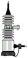
本发明实施例提供的一种智能型熔断器,包括:上述的熔断器(或称熔断器本体)、智能监测底座111以及CT环112。An intelligent fuse provided by an embodiment of the present invention includes: the above-mentioned fuse (or fuse body), an
智能型熔断器可以安装于配网变压器一次侧A、B、C三相线路上,可保护配网线路,同时实现熔断器运行状态的监测,也可进行线路电流、电场的实时采集。安装于A、B、C三相线路的三个智能型熔断器为一组。Intelligent fuses can be installed on the three-phase lines A, B, and C on the primary side of the distribution network transformer, which can protect the distribution network lines, and at the same time realize the monitoring of the operating status of the fuses, as well as real-time collection of line current and electric field. Three intelligent fuses installed in A, B, and C three-phase lines form a group.
智能型熔断器中的MCU供电电源选取方法可以包括如下规则:The MCU power supply selection method in the intelligent fuse can include the following rules:
规则一:当测量的电流值大于0.5A,即可选用感应取电传感器实现在线连续取电,满足智能型熔断器间隔5s(此间隔可设置)采集一次电流、电场数据,间隔5min(此间隔可设置)向管理终端上报一次数据的基本功能,此时,无线模块的射频电路间隔一定时间开启;Rule 1: When the measured current value is greater than 0.5A, the inductive power-taking sensor can be selected to realize online continuous power-taking, which meets the requirement of intelligent fuses to collect current and electric field data once every 5s (this interval can be set), and the interval is 5min (this interval Configurable) The basic function of reporting data to the management terminal once, at this time, the radio frequency circuit of the wireless module is turned on at regular intervals;
规则二:智能型熔断器支持数据实时上报;当测量的电流值大于大于 3A时,在线连续取电的供电电量即能满足立即实时上报的功能,支持无线模块的射频电路处于一直开启状态。Rule 2: Smart fuses support real-time data reporting; when the measured current value is greater than 3A, the power supply of continuous online power supply can meet the function of immediate real-time reporting, and the radio frequency circuit that supports the wireless module is always on.
规则三:优先选取在线连续取电的供电方式,当测量的电流值不能满足智能型熔断器运行工况所需的电量要求,无法完成在线连续取电时,选用超级电容作为后备电源为设备供电。Rule 3: Prioritize the power supply mode of online continuous power acquisition. When the measured current value cannot meet the power requirements required by the operating conditions of the smart fuse and cannot complete online continuous power acquisition, use super capacitors as backup power to supply power to the equipment .
规则四:若超级电容放电电压低于阈值,则超级电容也无法供电;当感应取电传感器和超级电容均无法为设备供电时,则选取电池供电。Rule 4: If the discharge voltage of the supercapacitor is lower than the threshold, the supercapacitor cannot supply power; when neither the inductive power-taking sensor nor the supercapacitor can supply power for the device, the battery is selected for power supply.
管理终端113可安装于JP柜、配网二次设备等处,配合智能型熔断器工作,具备数据采集、分析及异常上报、管理等功能。一个管理终端可同时接收至少一组熔断器的上传数据,实现对至少一组熔断器的管理。管理终端 113通过微功率无线对多组智能型熔断器监测数据进行采集,并通过边缘计算分析与处理,支持本地以RS232/485方式与其他配网设备进行数据交互,将结果上传至系统主站114;同时支持远程4G方式传输至系统主站114。The
系统主站114通过数据库管理和上报信息分析,可快速判断配网线路运行情况,生成报表记录和工单,为配网运检提供可靠的数据支撑。Through database management and reported information analysis, the
本发明的技术方案的熔断器的监测系统中,包括设置于熔断器底部的智能监测底座、套于所述熔断器的下引线处的CT环、以及管理终端;其中,所述智能监测底座中包括:PCB板、焊接于PCB板上的电路元件,以及铺覆于所述PCB板上、下表面的一对铜箔;所述CT环中包括电流测量传感器;所述焊接于PCB板上的电路元件包括:电场测量模块、第一放大器、MCU、第二放大器、无线模块;其中,所述电场测量模块用于对所述铜箔形成的电势差进行测量,将测量的电场值输出到第一放大器;经第一放大器放大的信号输入到所述MCU;所述电流测量传感器用于测量所述熔断器所在线路的电流,并将测量的电流值输出到第二放大器;经第二放大器放大的信号输入到所述MCU;所述MCU将测量的电流值、电场值通过所述无线模块上报所述管理终端;所述管理终端根据上报的电流值、电场值判断所述熔断器熔丝熔断,或所述熔断器所在线路出现停电故障。由于只需在熔断器底部安装智能监测底座、在熔断器的下引线处套上CT环,结构简单、不影响外观、易于安装,且不仅可以对熔断器熔丝状态进行监测,还可以对线路是否存在其它状况,如停电等情况进行监测。The fuse monitoring system of the technical solution of the present invention includes an intelligent monitoring base arranged at the bottom of the fuse, a CT ring set at the lower lead of the fuse, and a management terminal; wherein, the intelligent monitoring base It includes: a PCB board, circuit elements welded on the PCB board, and a pair of copper foils covered on the PCB board and the lower surface; the CT ring includes a current measurement sensor; the soldered on the PCB board The circuit components include: an electric field measurement module, a first amplifier, an MCU, a second amplifier, and a wireless module; wherein, the electric field measurement module is used to measure the potential difference formed by the copper foil, and output the measured electric field value to the first Amplifier; the signal amplified by the first amplifier is input to the MCU; the current measurement sensor is used to measure the current of the line where the fuse is located, and the measured current value is output to the second amplifier; the amplified signal of the second amplifier The signal is input to the MCU; the MCU reports the measured current value and electric field value to the management terminal through the wireless module; the management terminal judges that the fuse of the fuse is blown according to the reported current value and electric field value, Or a power failure occurs on the line where the fuse is located. Since it is only necessary to install an intelligent monitoring base at the bottom of the fuse and put a CT ring on the lower lead of the fuse, the structure is simple, does not affect the appearance, and is easy to install. Not only can the state of the fuse be monitored, but also the circuit Whether there are other conditions, such as power outages, etc. are monitored.
进一步,本发明的技术方案中,管理终端还可判断低电量事件、通信故障。Further, in the technical solution of the present invention, the management terminal can also judge low battery events and communication failures.
本实施例的计算机可读介质包括永久性和非永久性、可移动和非可移动媒体可以由任何方法或技术来实现信息存储。信息可以是计算机可读指令、数据结构、程序的模块或其他数据。计算机的存储介质的例子包括,但不限于相变内存(PRAM)、静态随机存取存储器(SRAM)、动态随机存取存储器 (DRAM)、其他类型的随机存取存储器(RAM)、只读存储器(ROM)、电可擦除可编程只读存储器(EEPROM)、快闪记忆体或其他内存技术、只读光盘只读存储器(CD-ROM)、数字多功能光盘(DVD)或其他光学存储、磁盒式磁带,磁带磁磁盘存储或其他磁性存储设备或任何其他非传输介质,可用于存储可以被计算设备访问的信息。The computer-readable medium in this embodiment includes permanent and non-permanent, removable and non-removable media, and information storage can be realized by any method or technology. Information may be computer readable instructions, data structures, modules of a program, or other data. Examples of computer storage media include, but are not limited to, phase change memory (PRAM), static random access memory (SRAM), dynamic random access memory (DRAM), other types of random access memory (RAM), read only memory (ROM), Electrically Erasable Programmable Read-Only Memory (EEPROM), Flash memory or other memory technology, Compact Disc Read-Only Memory (CD-ROM), Digital Versatile Disc (DVD) or other optical storage, Magnetic tape cartridge, tape magnetic disk storage or other magnetic storage device or any other non-transmission medium that can be used to store information that can be accessed by a computing device.
所属领域的普通技术人员应当理解:以上任何实施例的讨论仅为示例性的,并非旨在暗示本公开的范围(包括权利要求)被限于这些例子;在本发明的思路下,以上实施例或者不同实施例中的技术特征之间也可以进行组合,步骤可以以任意顺序实现,并存在如上所述的本发明的不同方面的许多其它变化,为了简明它们没有在细节中提供。Those of ordinary skill in the art should understand that: the discussion of any of the above embodiments is exemplary only, and is not intended to imply that the scope of the present disclosure (including claims) is limited to these examples; under the idea of the present invention, the above embodiments or Combinations between technical features in different embodiments are also possible, steps may be carried out in any order, and there are many other variations of the different aspects of the invention as described above, which are not presented in detail for the sake of brevity.
另外,为简化说明和讨论,并且为了不会使本发明难以理解,在所提供的附图中可以示出或可以不示出与集成电路(IC)芯片和其它部件的公知的电源/接地连接。此外,可以以框图的形式示出装置,以便避免使本发明难以理解,并且这也考虑了以下事实,即关于这些框图装置的实施方式的细节是高度取决于将要实施本发明的平台的(即,这些细节应当完全处于本领域技术人员的理解范围内)。在阐述了具体细节(例如,电路)以描述本发明的示例性实施例的情况下,对本领域技术人员来说显而易见的是,可以在没有这些具体细节的情况下或者这些具体细节有变化的情况下实施本发明。因此,这些描述应被认为是说明性的而不是限制性的。Additionally, well-known power/ground connections to integrated circuit (IC) chips and other components may or may not be shown in the provided figures, for simplicity of illustration and discussion, and so as not to obscure the present invention. . Furthermore, devices may be shown in block diagram form in order to avoid obscuring the invention, and this also takes into account the fact that details regarding the implementation of these block diagram devices are highly dependent on the platform on which the invention is to be implemented (i.e. , these details should be well within the understanding of those skilled in the art). Where specific details (eg, circuits) have been set forth to describe example embodiments of the invention, it will be apparent to those skilled in the art that other embodiments may be implemented without or with variations from these specific details. Implement the present invention down. Accordingly, these descriptions should be regarded as illustrative rather than restrictive.
尽管已经结合了本发明的具体实施例对本发明进行了描述,但是根据前面的描述,这些实施例的很多替换、修改和变型对本领域普通技术人员来说将是显而易见的。例如,其它存储器架构(例如,动态RAM(DRAM)) 可以使用所讨论的实施例。Although the invention has been described in conjunction with specific embodiments of the invention, many alternatives, modifications and variations of those embodiments will be apparent to those of ordinary skill in the art from the foregoing description. For example, other memory architectures such as dynamic RAM (DRAM) may use the discussed embodiments.
本发明的实施例旨在涵盖落入所附权利要求的宽泛范围之内的所有这样的替换、修改和变型。因此,凡在本发明的精神和原则之内,所做的任何省略、修改、等同替换、改进等,均应包含在本发明的保护范围之内。Embodiments of the present invention are intended to embrace all such alterations, modifications and variations that fall within the broad scope of the appended claims. Therefore, any omissions, modifications, equivalent replacements, improvements, etc. within the spirit and principles of the present invention shall be included within the protection scope of the present invention.
Claims (10)
Translated fromChinesePriority Applications (1)
| Application Number | Priority Date | Filing Date | Title |
|---|---|---|---|
| CN202010844636.XACN112345927B (en) | 2020-08-20 | 2020-08-20 | Fuse monitoring system and intelligent fuse |
Applications Claiming Priority (1)
| Application Number | Priority Date | Filing Date | Title |
|---|---|---|---|
| CN202010844636.XACN112345927B (en) | 2020-08-20 | 2020-08-20 | Fuse monitoring system and intelligent fuse |
Publications (2)
| Publication Number | Publication Date |
|---|---|
| CN112345927A CN112345927A (en) | 2021-02-09 |
| CN112345927Btrue CN112345927B (en) | 2023-07-07 |
Family
ID=74357860
Family Applications (1)
| Application Number | Title | Priority Date | Filing Date |
|---|---|---|---|
| CN202010844636.XAActiveCN112345927B (en) | 2020-08-20 | 2020-08-20 | Fuse monitoring system and intelligent fuse |
Country Status (1)
| Country | Link |
|---|---|
| CN (1) | CN112345927B (en) |
Families Citing this family (1)
| Publication number | Priority date | Publication date | Assignee | Title |
|---|---|---|---|---|
| CN116742794B (en)* | 2023-04-28 | 2024-03-29 | 北京国电通网络技术有限公司 | Intelligent monitoring equipment and methods for closed jet fuses |
Citations (8)
| Publication number | Priority date | Publication date | Assignee | Title |
|---|---|---|---|---|
| US4563628A (en)* | 1982-10-12 | 1986-01-07 | Baker Industries, Inc. | Supervision system for monitoring the condition of a battery and a series-connected fuse |
| FR2689677A1 (en)* | 1992-04-03 | 1993-10-08 | Electricite De France | Device for monitoring state of multistranded fuse in grid network - has constant current source connected to fuse and potential difference across fuse is measured to determine resistance |
| CN104779661A (en)* | 2014-01-15 | 2015-07-15 | 株式会社牧田 | Battery pack |
| CN106771842A (en)* | 2016-11-30 | 2017-05-31 | 国网浙江诸暨市供电公司 | A kind of fuse on-line monitoring system |
| CN206223902U (en)* | 2016-11-30 | 2017-06-06 | 国网浙江诸暨市供电公司 | A kind of fuse on-Line Monitor Device |
| CN108957219A (en)* | 2018-06-14 | 2018-12-07 | 山东卓尔电气有限公司 | A kind of fuse switch on-line fault monitoring method and device |
| CN110703161A (en)* | 2019-09-18 | 2020-01-17 | 国网江苏省电力有限公司淮安市洪泽区供电分公司 | An online monitoring system for distribution line fuses |
| CN110703162A (en)* | 2019-09-18 | 2020-01-17 | 国网江苏省电力有限公司淮安市洪泽区供电分公司 | A kind of distribution line fuse fault detection device |
Family Cites Families (4)
| Publication number | Priority date | Publication date | Assignee | Title |
|---|---|---|---|---|
| EP1262014B1 (en)* | 2000-02-07 | 2009-07-01 | ebm-papst St. Georgen GmbH & Co. KG | Arrangement for supplying a user, especially a d.c. motor, that consumes power in a non-continuous manner from a d.c. system |
| US8686596B2 (en)* | 2007-01-05 | 2014-04-01 | Roy Allen Huss | Fuse box system and method |
| US20100246080A1 (en)* | 2009-03-26 | 2010-09-30 | Optisolar, Inc., A Delaware Corporation | Intelligent fuse-holder |
| US8218274B2 (en)* | 2009-12-15 | 2012-07-10 | Eaton Corporation | Direct current arc fault circuit interrupter, direct current arc fault detector, noise blanking circuit for a direct current arc fault circuit interrupter, and method of detecting arc faults |
- 2020
- 2020-08-20CNCN202010844636.XApatent/CN112345927B/enactiveActive
Patent Citations (8)
| Publication number | Priority date | Publication date | Assignee | Title |
|---|---|---|---|---|
| US4563628A (en)* | 1982-10-12 | 1986-01-07 | Baker Industries, Inc. | Supervision system for monitoring the condition of a battery and a series-connected fuse |
| FR2689677A1 (en)* | 1992-04-03 | 1993-10-08 | Electricite De France | Device for monitoring state of multistranded fuse in grid network - has constant current source connected to fuse and potential difference across fuse is measured to determine resistance |
| CN104779661A (en)* | 2014-01-15 | 2015-07-15 | 株式会社牧田 | Battery pack |
| CN106771842A (en)* | 2016-11-30 | 2017-05-31 | 国网浙江诸暨市供电公司 | A kind of fuse on-line monitoring system |
| CN206223902U (en)* | 2016-11-30 | 2017-06-06 | 国网浙江诸暨市供电公司 | A kind of fuse on-Line Monitor Device |
| CN108957219A (en)* | 2018-06-14 | 2018-12-07 | 山东卓尔电气有限公司 | A kind of fuse switch on-line fault monitoring method and device |
| CN110703161A (en)* | 2019-09-18 | 2020-01-17 | 国网江苏省电力有限公司淮安市洪泽区供电分公司 | An online monitoring system for distribution line fuses |
| CN110703162A (en)* | 2019-09-18 | 2020-01-17 | 国网江苏省电力有限公司淮安市洪泽区供电分公司 | A kind of distribution line fuse fault detection device |
Non-Patent Citations (1)
| Title |
|---|
| 10kV线路跌落式熔断器在线监测终端系统;赵春林;江玉成;高健宁;;农村电气化(第09期);全文* |
Also Published As
| Publication number | Publication date |
|---|---|
| CN112345927A (en) | 2021-02-09 |
Similar Documents
| Publication | Publication Date | Title |
|---|---|---|
| KR101097267B1 (en) | Energy storage system and controlling method of the same | |
| CN202929124U (en) | Intelligent On-Line Monitoring System of High Voltage Shunt Capacitor in Substation | |
| CN204669077U (en) | On-Line UPS | |
| WO2019237704A1 (en) | Method and system for detecting leakage abnormality of capacitor, and computer device | |
| CN102854366B (en) | Low current measuring device and low current measuring method in direct-current power distribution and consumption system | |
| CN112345927B (en) | Fuse monitoring system and intelligent fuse | |
| CN202903947U (en) | Line fault indicator | |
| CN111999608B (en) | Monitoring method and monitoring system of distribution transformer and intelligent terminal | |
| KR101332304B1 (en) | surge protecting system for energy storage apparatus and method therefor | |
| CN117894647A (en) | A smart fuse | |
| CN204302468U (en) | Lithium battery on-line monitoring early warning system | |
| KR101412301B1 (en) | Apparatus of monitering characteristic of solar cell module using rfid | |
| CN107017835B (en) | The fault monitoring system and method for photovoltaic module | |
| CN211180059U (en) | Explosion-proof intelligent fault indicator | |
| CN118731530A (en) | Real-time online monitoring method and system for power load of power distribution equipment | |
| CN102735289A (en) | Wireless digital monitoring sensor for electrical equipment | |
| CN103760431A (en) | Integrated online monitoring device of parallel capacitor | |
| CN102332697A (en) | Measuring transient electrical activity in aircraft power distribution systems | |
| CN206431193U (en) | Monitoring alarm temporarily drops in line voltage | |
| CN206594242U (en) | A kind of electric energy quality on-line monitoring device | |
| CN209182488U (en) | A fault determination device | |
| CN203070449U (en) | Unmanned battery jar anti-theft alarm of backup power source | |
| CN202166717U (en) | DC power supply insulation fault detection device | |
| CN108594139B (en) | Method for detecting critical failure of battery | |
| CN105628245A (en) | Device, system and method of carrying out online detection on battery surface temperature |
Legal Events
| Date | Code | Title | Description |
|---|---|---|---|
| PB01 | Publication | ||
| PB01 | Publication | ||
| SE01 | Entry into force of request for substantive examination | ||
| SE01 | Entry into force of request for substantive examination | ||
| GR01 | Patent grant | ||
| GR01 | Patent grant |