CN112332075A - A multi-beam phased array integrated system and method - Google Patents
A multi-beam phased array integrated system and methodDownload PDFInfo
- Publication number
- CN112332075A CN112332075ACN202011205901.6ACN202011205901ACN112332075ACN 112332075 ACN112332075 ACN 112332075ACN 202011205901 ACN202011205901 ACN 202011205901ACN 112332075 ACN112332075 ACN 112332075A
- Authority
- CN
- China
- Prior art keywords
- module
- beam network
- amplification
- power
- phased array
- Prior art date
- Legal status (The legal status is an assumption and is not a legal conclusion. Google has not performed a legal analysis and makes no representation as to the accuracy of the status listed.)
- Granted
Links
Images


Classifications
- H—ELECTRICITY
- H01—ELECTRIC ELEMENTS
- H01Q—ANTENNAS, i.e. RADIO AERIALS
- H01Q1/00—Details of, or arrangements associated with, antennas
- H01Q1/12—Supports; Mounting means
- H01Q1/22—Supports; Mounting means by structural association with other equipment or articles
- H—ELECTRICITY
- H01—ELECTRIC ELEMENTS
- H01Q—ANTENNAS, i.e. RADIO AERIALS
- H01Q1/00—Details of, or arrangements associated with, antennas
- H01Q1/36—Structural form of radiating elements, e.g. cone, spiral, umbrella; Particular materials used therewith
- H—ELECTRICITY
- H01—ELECTRIC ELEMENTS
- H01Q—ANTENNAS, i.e. RADIO AERIALS
- H01Q1/00—Details of, or arrangements associated with, antennas
- H01Q1/50—Structural association of antennas with earthing switches, lead-in devices or lightning protectors
- H—ELECTRICITY
- H01—ELECTRIC ELEMENTS
- H01Q—ANTENNAS, i.e. RADIO AERIALS
- H01Q1/00—Details of, or arrangements associated with, antennas
- H01Q1/52—Means for reducing coupling between antennas; Means for reducing coupling between an antenna and another structure
- H01Q1/521—Means for reducing coupling between antennas; Means for reducing coupling between an antenna and another structure reducing the coupling between adjacent antennas
- H01Q1/523—Means for reducing coupling between antennas; Means for reducing coupling between an antenna and another structure reducing the coupling between adjacent antennas between antennas of an array
- H—ELECTRICITY
- H01—ELECTRIC ELEMENTS
- H01Q—ANTENNAS, i.e. RADIO AERIALS
- H01Q21/00—Antenna arrays or systems
- H01Q21/06—Arrays of individually energised antenna units similarly polarised and spaced apart
- H—ELECTRICITY
- H01—ELECTRIC ELEMENTS
- H01Q—ANTENNAS, i.e. RADIO AERIALS
- H01Q3/00—Arrangements for changing or varying the orientation or the shape of the directional pattern of the waves radiated from an antenna or antenna system
- H01Q3/26—Arrangements for changing or varying the orientation or the shape of the directional pattern of the waves radiated from an antenna or antenna system varying the relative phase or relative amplitude of energisation between two or more active radiating elements; varying the distribution of energy across a radiating aperture
- H01Q3/30—Arrangements for changing or varying the orientation or the shape of the directional pattern of the waves radiated from an antenna or antenna system varying the relative phase or relative amplitude of energisation between two or more active radiating elements; varying the distribution of energy across a radiating aperture varying the relative phase between the radiating elements of an array
- H01Q3/34—Arrangements for changing or varying the orientation or the shape of the directional pattern of the waves radiated from an antenna or antenna system varying the relative phase or relative amplitude of energisation between two or more active radiating elements; varying the distribution of energy across a radiating aperture varying the relative phase between the radiating elements of an array by electrical means
Landscapes
- Variable-Direction Aerials And Aerial Arrays (AREA)
Abstract
Translated fromChinese
Description
Translated fromChinese技术领域technical field
本发明涉及相控阵技术领域,更具体涉及一种多波束相控阵集成系统及方法。The invention relates to the technical field of phased arrays, and more particularly to a multi-beam phased array integration system and method.
背景技术Background technique
多波束相控阵天线是目前卫星载荷中最重要的一种天线形式,具有灵活的波束控制能力,波束间独立控制,可同时服务多个用户,也可在不同用户终端之间快速跳变。从国外通信卫星发展来看,最新发射的通信卫星系统多数搭载了一幅或多幅相控阵天线,提高波束的调度灵活能力,与反射面天线形成能力相互补充。随着卫星工作频率逐渐增高,毫米波频段由于其高带宽、小尺寸、轻重量和较好的抗干扰特点,在通信卫星中广泛使用。Multi-beam phased array antenna is the most important antenna form in satellite payloads at present. It has flexible beam steering capability, independent control between beams, can serve multiple users at the same time, and can also quickly jump between different user terminals. From the perspective of the development of foreign communication satellites, most of the newly launched communication satellite systems are equipped with one or more phased array antennas to improve the flexibility of beam scheduling and complement each other with the ability to form reflector antennas. As the operating frequency of satellites gradually increases, the millimeter-wave frequency band is widely used in communication satellites due to its high bandwidth, small size, light weight and better anti-jamming characteristics.
然而多波束相控阵通道规模大,是波束数量和通道数量两个维度的矩阵,即包含“M波束×N单元”个通道,特别是毫米波相控阵,尺寸小,阵元数量较多,多波束形成时,波束形成网络内包含大量的通道,以400阵元,8波束为例,需要在有限的空间内实现3200个波束通道,若不进行集成,系统的复杂度、设备量、体积和重量将会非常庞大,几乎不可能在星载平台上使用。However, the multi-beam phased array channel scale is large, and it is a matrix of two dimensions: the number of beams and the number of channels, that is, it contains "M beam × N units" channels, especially the millimeter wave phased array, which is small in size and has a large number of array elements. , In the case of multi-beam forming, the beam forming network contains a large number of channels. Taking 400 array elements and 8 beams as an example, 3200 beam channels need to be realized in a limited space. The volume and weight will be so huge that it is almost impossible to use it on a spaceborne platform.
毫米波两维有源多波束相控阵面临的问题就是在有限的空间内实现高复杂度波束形成网络的系统集成,一个好的集成方案对系统可实现性、装配可操作性、质量可靠性、复杂度以及系统散热等均会带来质的飞跃,因此一个合理的集成化方案是毫米波两维多波束相控阵的核心。The problem faced by the millimeter-wave two-dimensional active multi-beam phased array is to realize the system integration of the high-complexity beamforming network in a limited space. , complexity and system heat dissipation will bring about a qualitative leap, so a reasonable integrated solution is the core of the millimeter-wave two-dimensional multi-beam phased array.
既然波束形成网络是波束数量和通道数量两个维度的矩阵,可以在通道维度和波束维度集成,将波束形成矩阵划分成若干个“m波束×n单元”的子矩阵进行集成。Since the beamforming network is a matrix of two dimensions, the number of beams and the number of channels, it can be integrated in the channel dimension and the beam dimension, and the beamforming matrix can be divided into several sub-matrices of "m beam × n units" for integration.
随着子矩阵规模的变大,系统设备量、体积、重量、复杂度将会增加。但是并不是集成规模越大越好,过大规模的集成度将会带来以下缺点:子阵的体积过大,影响系统安装空间划分的灵活性和空间利用率;随着规模的增加,子阵内部的功分合成网络越复杂,子阵内部的体积利用下降;规模越大集成难度越大,给设计加工带来困难。As the scale of the sub-matrix becomes larger, the amount, volume, weight and complexity of the system equipment will increase. However, it is not that the larger the integration scale is, the better. Excessive large-scale integration will bring the following disadvantages: the volume of the sub-array is too large, which affects the flexibility and space utilization of the system installation space; as the scale increases, the sub-array will The more complex the internal power division synthesis network is, the smaller the volume utilization inside the sub-array is; the larger the scale is, the more difficult it is to integrate, which brings difficulties to the design and processing.
中国专利申请号CN202010218253.1,公开一种EHF频段相控阵天线,包括:辐射阵模块、TR组件模块、功率调整模块、波控组件模块以及散热组件模块,其中,所述辐射阵模块与TR组件模块沿水平方向面对面连接,所述功率调整模块和波控组件模块沿竖直方向面对面连接后,再作为一个整体与所述TR组件模块面对面连接,所述散热组件模块与所述TR组件模块相连接。该专利申请的天线结构紧凑,TR组件数量可灵活配置,散热效果好,但是其并不涉及多波束相控阵集成,不能解决现有技术多波束相控阵的集成问题。Chinese Patent Application No. CN202010218253.1 discloses an EHF frequency band phased array antenna, including: a radiation array module, a TR component module, a power adjustment module, a wave control component module and a heat dissipation component module, wherein the radiation array module and the TR The component modules are connected face-to-face along the horizontal direction, and after the power adjustment module and the wave control component module are connected face-to-face along the vertical direction, they are then connected face-to-face with the TR component module as a whole, and the heat dissipation component module is connected to the TR component module. connected. The antenna of this patent application has a compact structure, the number of TR components can be flexibly configured, and the heat dissipation effect is good, but it does not involve the integration of multi-beam phased arrays, and cannot solve the integration problem of multi-beam phased arrays in the prior art.
发明内容SUMMARY OF THE INVENTION
本发明所要解决的技术问题在于现有技术难以集成多波束相控阵,导致系统设备量、体积、重量和复杂度增大以及空间利用率减小的问题。The technical problem to be solved by the present invention is that it is difficult to integrate the multi-beam phased array in the prior art, which leads to the problems that the amount, volume, weight and complexity of the system equipment are increased and the space utilization rate is reduced.
本发明通过以下技术手段实现解决上述技术问题的:一种多波束相控阵集成系统,包括天线阵面、结构热控一体化板、放大组件、波束网络模块、1:N功分器以及供电控制模块,所述天线阵面包括若干个天线单元,每个天线单元均分别穿过结构热控一体化板与一个放大组件连接,所述放大组件与波束网络模块正交互联且盲配连接,所述波束网络模块分别与1:N功分器以及供电控制模块正交互联且盲配连接。The present invention solves the above technical problems through the following technical means: a multi-beam phased array integrated system, including an antenna array, a structural thermal control integrated board, an amplifier assembly, a beam network module, a 1:N power divider and a power supply a control module, the antenna front includes a plurality of antenna units, each antenna unit is respectively connected to an amplification component through a structural thermal control integrated board, the amplification component and the beam network module are orthogonally interconnected and blindly connected, The beam network module is respectively orthogonally interconnected with the 1:N power divider and the power supply control module and connected blindly.
本发明可扩展性较强,采用独立的功能模块设计,首先在规模上可扩展,从最小32单元,到几千个单元均可采用本发明的集成技术进行扩展,而不需要对各有源模块的硬件设计进行改动,同时采用模块正交互联,无板内垂直互联,系统复杂度降低,性能更优,由于能够进行模块化集成,减小了系统设备量、体积以及重量,同时提高了空间利用率。The invention has strong expansibility, adopts independent function module design, and can be expanded in scale firstly. The hardware design of the module is modified, and the module is orthogonally interconnected, and there is no vertical interconnection within the board, the system complexity is reduced, and the performance is better. Space utilization.
进一步地,所述天线单元排列方式为矩形栅格或者三角形栅格,天线单元用于空间无线信号的接收或向空间辐射无线信号。Further, the antenna units are arranged in a rectangular grid or a triangular grid, and the antenna units are used for receiving wireless signals in space or radiating wireless signals into space.
进一步地,所述每个天线单元均分别穿过结构热控一体化板与一个放大组件盲配连接。Further, each of the antenna units is blindly connected to an amplifying assembly through a structural thermal control integrated board, respectively.
进一步地,所述放大组件包括第一放大器、滤波器、第二放大器以及若干第一1:2功分器,第一放大器的输入端作为放大组件的输入端,第一放大器的输出端通过滤波器以及第二放大器与一个第一1:2功分器的输入端连接完成一级级联,该第一1:2功分器的两个输出端分别接一个第一1:2功分器的输入端完成二级级联,所有经K级级联的第一1:2功分器的所有输出端均接一个第一1:2功分器的输入端完成K+1级级联,实现放大组件的多通道输出,其中,K为大于等于1的正整数。Further, the amplifying component includes a first amplifier, a filter, a second amplifier and several first 1:2 power dividers, the input end of the first amplifier is used as the input end of the amplifying component, and the output end of the first amplifier is filtered The first 1:2 power divider is connected to the input end of the first 1:2 power divider to complete the cascade, and the two output ends of the first 1:2 power divider are respectively connected to a first 1:2 power divider The input end of the 1:2 power divider is connected to the input end of the first 1:2 power divider to complete the two-stage cascade. Realize the multi-channel output of the amplifying component, where K is a positive integer greater than or equal to 1.
进一步地,所述波束网络模块包括若干第二1:2功分器、若干第一移相器、若干第一衰减器、若干第二移相器以及若干第二衰减器,所有第二1:2功分器的输入端作为波束网络模块的输入通道,所有第二1:2功分器的第一输出端均连接一个第一移相器,所有第一移相器均单独连接一个第一衰减器,所有第一衰减器的输出端连接到一起作为波束网络模块的一个输出端,所有第二1:2功分器的第二输出端均连接一个第二移相器,所有第二移相器均单独连接一个第二衰减器,所有第二衰减器的输出端连接到一起作为波束网络模块的另一个输出端。Further, the beam network module includes several second 1:2 power dividers, several first phase shifters, several first attenuators, several second phase shifters and several second attenuators, all second 1:2: The input end of the 2 power divider is used as the input channel of the beam network module, the first output ends of all the second 1:2 power dividers are connected to a first phase shifter, and all the first phase shifters are connected to a first phase shifter individually. Attenuators, the outputs of all the first attenuators are connected together as one output of the beam network module, the second outputs of all the second 1:2 power dividers are connected to a second phase shifter, and all the second Each of the phasers is individually connected to a second attenuator, and the output ends of all the second attenuators are connected together as another output end of the beam network module.
更进一步地,每R个所述放大组件相互平行的叠放,每S个波束网络模块相互平行的叠放,R个所述放大组件的叠放方向与S个波束网络模块的叠放方向垂直,S个波束网络模块组成的整体与R个所述放大组件组成的整体连接,实现R个所述放大组件与S个波束网络模块的正交互联且盲配连接。Further, every R of the amplifying assemblies are stacked parallel to each other, and every S beam network modules are stacked parallel to each other, and the stacking direction of the R amplifying assemblies is perpendicular to the stacking direction of the S beam network modules. , the whole composed of the S beam network modules is connected to the whole composed of the R amplifying components, so as to realize the orthogonal interconnection and blind matching connection of the R amplifying components and the S beam network modules.
更进一步地,所述波束网络模块的输入通道为R个,R个所述放大组件中每个放大组件均与波束网络模块的一个输入通道连接。Further, there are R input channels of the beam network module, and each of the R amplification components is connected to one input channel of the beam network module.
更进一步地,所述放大组件的总数为M,所述1:N功分器的总数为


更进一步地,所述供电控制模块垂直于S个波束网络模块的叠放方向且与所有波束网络模块连接,实现供电控制模块与波束网络模块的正交互联及盲配连接;每个1:N功分器垂直于S个波束网络模块的叠放方向且与所有波束网络模块连接,实现1:N功分器与波束网络模块的正交互联及盲配连接。Further, the power supply control module is perpendicular to the stacking direction of the S beam network modules and is connected to all the beam network modules, so as to realize the orthogonal interconnection and blind matching connection between the power supply control module and the beam network module; each 1:N The power divider is perpendicular to the stacking direction of the S beam network modules and is connected to all the beam network modules, so as to realize the orthogonal interconnection and blind matching connection between the 1:N power divider and the beam network modules.
本发明还提供一种多波束相控阵集成系统的方法,所述方法包括:若干个天线单元用于空间无线信号的接收或向空间辐射无线信号,结构热控一体化板作为天线单元和放大组件的安装结构板,同时为放大组件散热,放大组件实现信号的低噪声放大或者功率放大,波束网络模块实现控制码的串并转换和各波束通道的移相衰减控制,1:N功分器接收波束网络模块的信号合成波束,供电控制模块给波束网络模块和放大组件提供电源并实现多波束相控阵的控制码计算和分发,进而控制波束的指向和形状。The present invention also provides a method for a multi-beam phased array integrated system, the method includes: a plurality of antenna units are used for receiving wireless signals in space or radiating wireless signals to space, a structural thermal control integrated board is used as the antenna unit and amplifying The installation structure board of the component, at the same time dissipates heat for the amplifying component, the amplifying component realizes low-noise amplification or power amplification of the signal, the beam network module realizes the serial-to-parallel conversion of the control code and the phase-shift attenuation control of each beam channel, 1:N power divider The signal of the receiving beam network module is synthesized into a beam, and the power supply control module provides power to the beam network module and amplifying components, and realizes the calculation and distribution of the control code of the multi-beam phased array, and then controls the direction and shape of the beam.
本发明的优点在于:The advantages of the present invention are:
(1)本发明可扩展性较强,采用独立的功能模块设计,首先在规模上可扩展,从最小32单元,到几千个单元均可采用本发明的集成技术进行扩展,而不需要对各有源模块的硬件设计进行改动,同时采用模块正交互联,无板内垂直互联,系统复杂度降低,性能更优,由于能够进行模块化集成,减小了系统设备量、体积以及重量,同时提高了空间利用率。(1) The present invention has strong expansibility, adopts independent functional module design, and is firstly scalable in scale, from a minimum of 32 units to several thousand units can be expanded by using the integrated technology of the present invention, without the need for The hardware design of each active module is modified, and the modules are orthogonally interconnected, and there is no vertical interconnection within the board, the system complexity is reduced, and the performance is better. At the same time, the space utilization rate is improved.
(2)本发明在波束数量可根据需要进行扩展,根据相控阵系统的应用需求,可在一定程度上进行波束数量扩展,在当前的工艺水平下,应用于高轨载荷的Ka波段相控阵,可从1个波束扩展到16个以上的模拟波束,在扩展过程中,各有源模块的硬件设计不需要改动。(2) The present invention can expand the number of beams according to the needs. According to the application requirements of the phased array system, the number of beams can be expanded to a certain extent. Under the current technological level, it can be applied to the Ka-band phase control of high orbit loads. The array can be expanded from 1 beam to more than 16 analog beams. During the expansion process, the hardware design of each active module does not need to be changed.
(3)本发明采用正交模块互联技术,相比于其他的互联技术,性能更优,在多波束形成时,由于各波束间信号交叉,需要垂直互联,传统的集成方案上常采用板内垂直互联,在毫米波频段,过多的垂直互联将造成波束间隔离、通道起伏、通道间一致性等性能恶化,而本发明的集成技术,采用模块正交互联,每个模块功能简单,无板内垂直互联,性能优异。(3) The present invention adopts orthogonal module interconnection technology, which has better performance than other interconnection technologies. During multi-beam formation, vertical interconnection is required due to signal crossing between beams. Traditional integration schemes often use intra-board Vertical interconnection. In the millimeter-wave frequency band, excessive vertical interconnection will cause performance deterioration such as isolation between beams, channel fluctuations, and consistency between channels. However, the integration technology of the present invention adopts orthogonal interconnection of modules, and each module has simple functions and no Vertical interconnection within the board, excellent performance.
附图说明Description of drawings
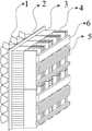
图1为本发明实施例所提供的一种多波束相控阵集成系统的整体结构示意图;FIG. 1 is a schematic diagram of the overall structure of a multi-beam phased array integrated system according to an embodiment of the present invention;
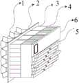
图2为本发明实施例所提供的一种多波束相控阵集成系统中32单元8波束情况下的示意图;2 is a schematic diagram of 32 units and 8 beams in a multi-beam phased array integrated system provided by an embodiment of the present invention;
图3为本发明实施例所提供的一种多波束相控阵集成系统中放大组件电路原理图;3 is a schematic diagram of an amplification component circuit in a multi-beam phased array integrated system according to an embodiment of the present invention;
图4为本发明实施例所提供的一种多波束相控阵集成系统中波束网络模块电路原理图;4 is a schematic circuit diagram of a beam network module in a multi-beam phased array integrated system according to an embodiment of the present invention;
图5为本发明实施例所提供的一种多波束相控阵集成系统中放大组件和波束网络模块连接示意图;5 is a schematic diagram of the connection between an amplification component and a beam network module in a multi-beam phased array integrated system according to an embodiment of the present invention;
图6为本发明实施例所提供的一种多波束相控阵集成系统中波束网络模块、1:N功分器以及供电控制模块连接方式立体示意图;FIG. 6 is a three-dimensional schematic diagram of a connection mode of a beam network module, a 1:N power divider, and a power supply control module in a multi-beam phased array integrated system according to an embodiment of the present invention;
图7为本发明实施例所提供的一种多波束相控阵集成系统中波束网络模块、1:N功分器以及供电控制模块立体的连接方式主视图;7 is a front view of a three-dimensional connection mode of a beam network module, a 1:N power divider, and a power supply control module in a multi-beam phased array integrated system according to an embodiment of the present invention;
图8为本发明实施例所提供的一种多波束相控阵集成系统中32单元8波束情况下的结构框图。FIG. 8 is a structural block diagram in the case of 32 elements and 8 beams in a multi-beam phased array integrated system provided by an embodiment of the present invention.
具体实施方式Detailed ways
为使本发明实施例的目的、技术方案和优点更加清楚,下面将结合本发明实施例,对本发明实施例中的技术方案进行清楚、完整地描述,显然,所描述的实施例是本发明一部分实施例,而不是全部的实施例。基于本发明中的实施例,本领域普通技术人员在没有作出创造性劳动前提下所获得的所有其他实施例,都属于本发明保护的范围。In order to make the purposes, technical solutions and advantages of the embodiments of the present invention clearer, the technical solutions in the embodiments of the present invention will be clearly and completely described below in conjunction with the embodiments of the present invention. Obviously, the described embodiments are part of the present invention. examples, but not all examples. Based on the embodiments of the present invention, all other embodiments obtained by those of ordinary skill in the art without creative efforts shall fall within the protection scope of the present invention.
如图1所示,一种多波束相控阵集成系统,包括天线阵面1、结构热控一体化板2、放大组件3、波束网络模块4、1:N功分器5以及供电控制模块6,所述天线阵面1包括若干个天线单元101,每个天线单元101均分别穿过结构热控一体化板2与一个放大组件3连接,所述放大组件3与波束网络模块4正交互联且盲配连接,所述波束网络模块4分别与1:N功分器5以及供电控制模块6正交互联且盲配连接。所述盲配连接指的是在没有电气或者光学连接点可见的情况下,通过机械导向如轨道、插槽等实现组件与组件之间的连接,所述正交互联指的是组件与组件之间相对旋转90度后连接,组件与组件之间位置关系为垂直。1:N功分器5为具有1路输入和N路输出的功分器,逆向时是具有N路输入和1路输出的合成器。图1只是展示各部件之间的连接关系,置于各部件的个数只是示意,并不是实际应用中的个数关系,实际应用中,各部件的个数可以根据需要选择,各部件的个数不同最后组合而成的系统输出的波束个数也不同。以下以32个天线单元101同时形成8波束为例,详细地描述本发明的各个部分。As shown in Figure 1, a multi-beam phased array integrated system includes an
如图2和图8所示,图8中,1#、2#等表示对应的部件属于第几个,例如放大组件1#表示第一个放大组件,所述天线单元101排列方式为矩形栅格或者三角形栅格,本实施例中采用矩形栅格,本实施例中天线单元101个数为32个,天线单元101用于空间无线信号的接收或向空间辐射无线信号。所述结构热控一体化板2为一块与天线单元101阵列形状相配合的板,本实施例中为矩形板,结构热控一体化板2作为天线单元101和放大组件3的安装结构板,同时其采用具有散热性能的散热材料制成,为放大组件3散热,所述每个天线单元101均分别穿过结构热控一体化板2与一个放大组件3盲配连接,与天线单元101相对应的,放大组件3个数也为32个。As shown in FIG. 2 and FIG. 8 , in FIG. 8, 1#, 2#, etc. represent the number of the corresponding components. For example, the amplifying
如图3所示,所述放大组件3包括第一放大器301、滤波器302、第二放大器303以及若干第一1:2功分器304,第一放大器301的输入端作为放大组件3的输入端,第一放大器301的输出端通过滤波器302以及第二放大器303与一个第一1:2功分器304的输入端连接完成一级级联,该第一1:2功分器304的两个输出端分别接一个第一1:2功分器304的输入端完成二级级联,所有经K级级联的第一1:2功分器304的所有输出端均接一个第一1:2功分器304的输入端完成K+1级级联,实现放大组件3的多通道输出,其中,K为大于等于1的正整数,本实施例中示意了4级级联,即K等于3。As shown in FIG. 3 , the amplifying
如图4所示,所述波束网络模块4包括若干第二1:2功分器401、若干第一移相器402、若干第一衰减器403、若干第二移相器404以及若干第二衰减器405,所有第二1:2功分器401的输入端作为波束网络模块4的输入通道,所有第二1:2功分器401的第一输出端均连接一个第一移相器402,所有第一移相器402均单独连接一个第一衰减器403,所有第一衰减器403的输出端连接到一起作为波束网络模块4的一个输出端,所有第二1:2功分器401的第二输出端均连接一个第二移相器404,所有第二移相器404均单独连接一个第二衰减器405,所有第二衰减器405的输出端连接到一起作为波束网络模块4的另一个输出端。As shown in FIG. 4 , the
每R个所述放大组件3相互平行的叠放,每S个波束网络模块4相互平行的叠放,R个所述放大组件3的叠放方向与S个波束网络模块4的叠放方向垂直,S个波束网络模块4组成的整体与R个所述放大组件3组成的整体连接,实现R个所述放大组件3与S个波束网络模块4的正交互联且盲配连接。如图5所示,本实施例中,R=8,S=4,即每8个所述放大组件3相互平行的叠放,每4个波束网络模块4相互平行的叠放,8个所述放大组件3的叠放方向与4个波束网络模块4的叠放方向垂直,4个波束网络模块4组成的整体与8个所述放大组件3组成的整体连接,实现8个所述放大组件3与4个波束网络模块4的正交互联且盲配连接。所述波束网络模块4的输入通道为8个,8个所述放大组件3中每个放大组件3均与波束网络模块4的一个输入通道连接。Every
所述放大组件3的总数为M,所述1:N功分器的总数为


图2结合图6以及图7,本实施例中,一个波束网络模块4具有两个输出端口,一个1:N功分器5具有4个输出端,因此逆向时其作为合成器时具有4个输入端,故两个波束网络模块4对应的需要与一个1:N功分器5连接,本实施例中共16个波束网络模块4就需要8个1:N功分器5,所述波束网络模块4分别与1:N功分器5以及供电控制模块6正交互联且盲配连接,所有1:N功分器5相互平行的错开预设距离并垂直于叠放在一起的波束网络模块4的叠放面,图中每个1:N功分器5的连接端口的位置决定了1:N功分器5整体布局错开。所述供电控制模块6有一个,供电控制模块6垂直于4个波束网络模块4的叠放方向且与所有波束网络模块4连接,实现供电控制模块6与波束网络模块4的正交互联及盲配连接;每个1:N功分器垂直于4个波束网络模块4的叠放方向且与所有波束网络模块4连接,实现1:N功分器与波束网络模块4的正交互联及盲配连接。FIG. 2 is combined with FIG. 6 and FIG. 7. In this embodiment, one
本发明还提供一种多波束相控阵集成系统的方法,所述方法包括:若干个天线单元101用于空间无线信号的接收或向空间辐射无线信号,结构热控一体化板2作为天线单元101和放大组件3的安装结构板,同时为放大组件3散热,放大组件3实现信号的低噪声放大或者功率放大,波束网络模块4实现控制码的串并转换和各波束通道的移相衰减控制,1:N功分器接收波束网络模块4的信号合成波束,供电控制模块6给波束网络模块4和放大组件3提供电源并实现多波束相控阵的控制码计算和分发,进而控制波束的指向和形状。The present invention also provides a method for a multi-beam phased array integrated system, the method includes: a plurality of
通过以上技术方案,本发明可扩展性较强,采用独立的功能模块设计,首先在规模上可扩展,从最小32单元,到几千个单元均可采用本发明的集成技术进行扩展,而不需要对各有源模块的硬件设计进行改动,同时采用模块正交互联,无板内垂直互联,系统复杂度降低,性能更优,由于能够进行模块化集成,减小了系统设备量、体积以及重量,同时提高了空间利用率。Through the above technical solutions, the present invention has strong expansibility, adopts independent functional module design, and is firstly scalable in scale, from a minimum of 32 units to several thousand units can be expanded using the integrated technology of the present invention, without The hardware design of each active module needs to be changed, and at the same time, the orthogonal interconnection of modules is adopted, and there is no vertical interconnection within the board. The system complexity is reduced and the performance is better. Due to the modular integration, the amount of system equipment, volume and weight, while improving space utilization.
以上实施例仅用以说明本发明的技术方案,而非对其限制;尽管参照前述实施例对本发明进行了详细的说明,本领域的普通技术人员应当理解:其依然可以对前述各实施例所记载的技术方案进行修改,或者对其中部分技术特征进行等同替换;而这些修改或者替换,并不使相应技术方案的本质脱离本发明各实施例技术方案的精神和范围。The above embodiments are only used to illustrate the technical solutions of the present invention, but not to limit them; although the present invention has been described in detail with reference to the foregoing embodiments, those of ordinary skill in the art should understand that: The recorded technical solutions are modified, or some technical features thereof are equivalently replaced; and these modifications or replacements do not make the essence of the corresponding technical solutions deviate from the spirit and scope of the technical solutions of the embodiments of the present invention.
Claims (10)


Priority Applications (1)
| Application Number | Priority Date | Filing Date | Title |
|---|---|---|---|
| CN202011205901.6ACN112332075B (en) | 2020-11-02 | 2020-11-02 | Multi-beam phased array integration system and method |
Applications Claiming Priority (1)
| Application Number | Priority Date | Filing Date | Title |
|---|---|---|---|
| CN202011205901.6ACN112332075B (en) | 2020-11-02 | 2020-11-02 | Multi-beam phased array integration system and method |
Publications (2)
| Publication Number | Publication Date |
|---|---|
| CN112332075Atrue CN112332075A (en) | 2021-02-05 |
| CN112332075B CN112332075B (en) | 2022-04-15 |
Family
ID=74324547
Family Applications (1)
| Application Number | Title | Priority Date | Filing Date |
|---|---|---|---|
| CN202011205901.6AActiveCN112332075B (en) | 2020-11-02 | 2020-11-02 | Multi-beam phased array integration system and method |
Country Status (1)
| Country | Link |
|---|---|
| CN (1) | CN112332075B (en) |
Cited By (2)
| Publication number | Priority date | Publication date | Assignee | Title |
|---|---|---|---|---|
| CN115632241A (en)* | 2022-10-31 | 2023-01-20 | 成都华芯天微科技有限公司 | Satellite-borne multi-beam phased array antenna for low-orbit satellite communication |
| CN117518109A (en)* | 2024-01-04 | 2024-02-06 | 中国科学院空天信息创新研究院 | Measurement method of temperature change characteristics of azimuth multi-channel spaceborne SAR antenna calibration network |
Citations (24)
| Publication number | Priority date | Publication date | Assignee | Title |
|---|---|---|---|---|
| EP1045473A2 (en)* | 1999-04-16 | 2000-10-18 | Robert Bosch Gmbh | Multibeam phased array antenna system |
| US6201508B1 (en)* | 1999-12-13 | 2001-03-13 | Space Systems/Loral, Inc. | Injection-molded phased array antenna system |
| US6429816B1 (en)* | 2001-05-04 | 2002-08-06 | Harris Corporation | Spatially orthogonal signal distribution and support architecture for multi-beam phased array antenna |
| US6538603B1 (en)* | 2000-07-21 | 2003-03-25 | Paratek Microwave, Inc. | Phased array antennas incorporating voltage-tunable phase shifters |
| WO2003047033A1 (en)* | 2001-11-21 | 2003-06-05 | Lockheed Martin Corporation | Scaleable antenna array architecture using standard radiating subarrays and amplifying/beamforming assemblies |
| US20050219137A1 (en)* | 2003-12-23 | 2005-10-06 | Heisen Peter T | Antenna apparatus and method |
| US7170446B1 (en)* | 2004-09-24 | 2007-01-30 | Rockwell Collins, Inc. | Phased array antenna interconnect having substrate slat structures |
| US20070285314A1 (en)* | 2006-06-09 | 2007-12-13 | The Regents Of The University Of Michigan | Phased array systems and phased array front-end devices |
| US20080030422A1 (en)* | 2006-07-11 | 2008-02-07 | John Gevargiz | Rfid antenna system |
| WO2008027650A2 (en)* | 2006-07-11 | 2008-03-06 | Mojix Inc. | Rfid system |
| US20080106484A1 (en)* | 2006-11-08 | 2008-05-08 | The Boeing Company | Compact, dual-beam phased array antenna architecture |
| US20080169973A1 (en)* | 2006-10-20 | 2008-07-17 | Lockheed Martin Corporation | Antenna with compact LRU array |
| CN105337046A (en)* | 2015-11-23 | 2016-02-17 | 中国电子科技集团公司第五十四研究所 | Sub-array level digital multi-beam satellite communication phased-array antenna |
| CN105914476A (en)* | 2016-05-20 | 2016-08-31 | 中国电子科技集团公司第十研究所 | Ka-band tilt-structure active phased array antenna |
| CN105958214A (en)* | 2016-05-09 | 2016-09-21 | 中国电子科技集团公司第三十八研究所 | Extensible highly-integrated active phased array antenna |
| CN106654541A (en)* | 2017-02-20 | 2017-05-10 | 成都瑞迪威科技有限公司 | Millimeter-wave 64 array element tile type phased array antenna |
| WO2017095832A1 (en)* | 2015-12-02 | 2017-06-08 | Raytheon Company | Dual-polarized wideband radiator with single-plane stripline feed |
| US20170346169A1 (en)* | 2016-05-31 | 2017-11-30 | Honeywell International Inc. | Integrated digital active phased array antenna and wingtip collision avoidance system |
| CN107465467A (en)* | 2017-07-28 | 2017-12-12 | 中国电子科技集团公司第三十八研究所 | A kind of modularization waveguide corrective network suitable for highly integrated phased array system |
| WO2018058722A1 (en)* | 2016-09-27 | 2018-04-05 | 南京肯微弗通信技术有限公司 | Dual-polarized waveguide array antenna shared by transmitting and receiving |
| RU2666577C1 (en)* | 2017-12-01 | 2018-09-11 | Акционерное общество "Ижевский радиозавод" | Receiving multi-beam active phased antenna array |
| CN208045702U (en)* | 2018-05-03 | 2018-11-02 | 桂林长海发展有限责任公司 | A kind of orthogonal synthesis inclined polarization active phase array antenna |
| US20200192179A1 (en)* | 2018-12-18 | 2020-06-18 | California Institute Of Technology | Optical Phased Arrays and Methods for Calibrating and Focusing of Optical Phased Arrays |
| CN111541002A (en)* | 2020-03-30 | 2020-08-14 | 西南电子技术研究所(中国电子科技集团公司第十研究所) | Active Phased Array Antenna for Missile-borne Communication System |
- 2020
- 2020-11-02CNCN202011205901.6Apatent/CN112332075B/enactiveActive
Patent Citations (25)
| Publication number | Priority date | Publication date | Assignee | Title |
|---|---|---|---|---|
| EP1045473A2 (en)* | 1999-04-16 | 2000-10-18 | Robert Bosch Gmbh | Multibeam phased array antenna system |
| US6201508B1 (en)* | 1999-12-13 | 2001-03-13 | Space Systems/Loral, Inc. | Injection-molded phased array antenna system |
| US6538603B1 (en)* | 2000-07-21 | 2003-03-25 | Paratek Microwave, Inc. | Phased array antennas incorporating voltage-tunable phase shifters |
| US6429816B1 (en)* | 2001-05-04 | 2002-08-06 | Harris Corporation | Spatially orthogonal signal distribution and support architecture for multi-beam phased array antenna |
| WO2003047033A1 (en)* | 2001-11-21 | 2003-06-05 | Lockheed Martin Corporation | Scaleable antenna array architecture using standard radiating subarrays and amplifying/beamforming assemblies |
| US20050219137A1 (en)* | 2003-12-23 | 2005-10-06 | Heisen Peter T | Antenna apparatus and method |
| US7170446B1 (en)* | 2004-09-24 | 2007-01-30 | Rockwell Collins, Inc. | Phased array antenna interconnect having substrate slat structures |
| US20070285314A1 (en)* | 2006-06-09 | 2007-12-13 | The Regents Of The University Of Michigan | Phased array systems and phased array front-end devices |
| US20080030422A1 (en)* | 2006-07-11 | 2008-02-07 | John Gevargiz | Rfid antenna system |
| WO2008027650A2 (en)* | 2006-07-11 | 2008-03-06 | Mojix Inc. | Rfid system |
| US20080169973A1 (en)* | 2006-10-20 | 2008-07-17 | Lockheed Martin Corporation | Antenna with compact LRU array |
| US20080106484A1 (en)* | 2006-11-08 | 2008-05-08 | The Boeing Company | Compact, dual-beam phased array antenna architecture |
| CN105337046A (en)* | 2015-11-23 | 2016-02-17 | 中国电子科技集团公司第五十四研究所 | Sub-array level digital multi-beam satellite communication phased-array antenna |
| WO2017095832A1 (en)* | 2015-12-02 | 2017-06-08 | Raytheon Company | Dual-polarized wideband radiator with single-plane stripline feed |
| CN108370100A (en)* | 2015-12-02 | 2018-08-03 | 雷声公司 | Dual polarization broadband radiator with monoplane strip line feed |
| CN105958214A (en)* | 2016-05-09 | 2016-09-21 | 中国电子科技集团公司第三十八研究所 | Extensible highly-integrated active phased array antenna |
| CN105914476A (en)* | 2016-05-20 | 2016-08-31 | 中国电子科技集团公司第十研究所 | Ka-band tilt-structure active phased array antenna |
| US20170346169A1 (en)* | 2016-05-31 | 2017-11-30 | Honeywell International Inc. | Integrated digital active phased array antenna and wingtip collision avoidance system |
| WO2018058722A1 (en)* | 2016-09-27 | 2018-04-05 | 南京肯微弗通信技术有限公司 | Dual-polarized waveguide array antenna shared by transmitting and receiving |
| CN106654541A (en)* | 2017-02-20 | 2017-05-10 | 成都瑞迪威科技有限公司 | Millimeter-wave 64 array element tile type phased array antenna |
| CN107465467A (en)* | 2017-07-28 | 2017-12-12 | 中国电子科技集团公司第三十八研究所 | A kind of modularization waveguide corrective network suitable for highly integrated phased array system |
| RU2666577C1 (en)* | 2017-12-01 | 2018-09-11 | Акционерное общество "Ижевский радиозавод" | Receiving multi-beam active phased antenna array |
| CN208045702U (en)* | 2018-05-03 | 2018-11-02 | 桂林长海发展有限责任公司 | A kind of orthogonal synthesis inclined polarization active phase array antenna |
| US20200192179A1 (en)* | 2018-12-18 | 2020-06-18 | California Institute Of Technology | Optical Phased Arrays and Methods for Calibrating and Focusing of Optical Phased Arrays |
| CN111541002A (en)* | 2020-03-30 | 2020-08-14 | 西南电子技术研究所(中国电子科技集团公司第十研究所) | Active Phased Array Antenna for Missile-borne Communication System |
Non-Patent Citations (3)
| Title |
|---|
| F. GOLCUK: "A 90-100 GHz 4 4 SiGe BiCMOS Polarimetric Transmit-Receive Phased Array with Simultaneous Receive-Beams Capabilities", 《IEEE》* |
| H. SHIOMI: "Phase-shifterless beam scanning of active phased array antenna using injection locked oscillator", 《IEEE》* |
| 李燕: "宽带宽角扫描相控阵天线研究", 《中国博士学位论文全文数据库》* |
Cited By (4)
| Publication number | Priority date | Publication date | Assignee | Title |
|---|---|---|---|---|
| CN115632241A (en)* | 2022-10-31 | 2023-01-20 | 成都华芯天微科技有限公司 | Satellite-borne multi-beam phased array antenna for low-orbit satellite communication |
| CN115632241B (en)* | 2022-10-31 | 2023-05-30 | 成都华芯天微科技有限公司 | Satellite-borne multi-beam phased array antenna for low-orbit satellite communication |
| CN117518109A (en)* | 2024-01-04 | 2024-02-06 | 中国科学院空天信息创新研究院 | Measurement method of temperature change characteristics of azimuth multi-channel spaceborne SAR antenna calibration network |
| CN117518109B (en)* | 2024-01-04 | 2024-03-12 | 中国科学院空天信息创新研究院 | Measurement method of temperature change characteristics of azimuth multi-channel spaceborne SAR antenna calibration network |
Also Published As
| Publication number | Publication date |
|---|---|
| CN112332075B (en) | 2022-04-15 |
Similar Documents
| Publication | Publication Date | Title |
|---|---|---|
| US9374145B2 (en) | Beam-forming network for an array antenna and array antenna comprising the same | |
| US6965279B2 (en) | Double-sided, edge-mounted stripline signal processing modules and modular network | |
| CN1150662C (en) | Integrated transmit/receive antenna with arbitrary use of antenna aperture | |
| US6297774B1 (en) | Low cost high performance portable phased array antenna system for satellite communication | |
| CN106602265B (en) | Beam forming network and input structure, input and output method and three-beam antenna thereof | |
| US5870063A (en) | Spacecraft with modular communication payload | |
| EP3618182A1 (en) | Dual-polarized fractal antenna feed architecture employing orthogonal parallel-plate modes | |
| US10103432B2 (en) | Multiband antenna with variable electrical tilt | |
| US6246364B1 (en) | Light-weight modular low-level reconfigurable beamformer for array antennas | |
| CN116207522B (en) | Dual-frequency dual-polarization common-caliber flat-plate antenna based on dual-cross waveguide structure | |
| US5329248A (en) | Power divider/combiner having wide-angle microwave lenses | |
| Lu et al. | Millimeter-wave low-profile continuous transverse stub arrays with novel linear source generators | |
| CN112332075B (en) | Multi-beam phased array integration system and method | |
| CN113161765A (en) | Light-weighted low-profile flat plate array antenna | |
| CN114188727A (en) | array antenna | |
| CN115296044B (en) | A multi-beam phased array antenna system | |
| EP0795928A2 (en) | Antenna with single or double reflector, with shaped beams and linear polarisation | |
| US4949092A (en) | Modularized contoured beam direct radiating antenna | |
| CN112467396B (en) | Novel broadband array antenna | |
| Ye et al. | Multibeam antenna based on butler matrix for 3G/LTE/5G/B5G base station applications | |
| Otto et al. | Planar Satcom antenna systems in Ka-band | |
| CN111262023A (en) | A Novel Low Profile Phased Array Antenna Based on Near-Field Space Feed Mechanism | |
| CN114586238B (en) | Mitigating beam skew in multi-beamforming networks | |
| Karimi et al. | Design of an amplitude-tapered corporate-feed slot array antenna with reduced side-lobe level for silicon micromachining | |
| CN221961231U (en) | Phased Array Antenna |
Legal Events
| Date | Code | Title | Description |
|---|---|---|---|
| PB01 | Publication | ||
| PB01 | Publication | ||
| SE01 | Entry into force of request for substantive examination | ||
| SE01 | Entry into force of request for substantive examination | ||
| GR01 | Patent grant | ||
| GR01 | Patent grant |