CN112330770B - An Automatic Generation System of Engineering Curve Groups - Google Patents
An Automatic Generation System of Engineering Curve GroupsDownload PDFInfo
- Publication number
- CN112330770B CN112330770BCN202011131592.2ACN202011131592ACN112330770BCN 112330770 BCN112330770 BCN 112330770BCN 202011131592 ACN202011131592 ACN 202011131592ACN 112330770 BCN112330770 BCN 112330770B
- Authority
- CN
- China
- Prior art keywords
- curve
- module
- point
- offset
- equation
- Prior art date
- Legal status (The legal status is an assumption and is not a legal conclusion. Google has not performed a legal analysis and makes no representation as to the accuracy of the status listed.)
- Active
Links
Images


Classifications
- G—PHYSICS
- G06—COMPUTING OR CALCULATING; COUNTING
- G06T—IMAGE DATA PROCESSING OR GENERATION, IN GENERAL
- G06T11/00—2D [Two Dimensional] image generation
- G06T11/20—Drawing from basic elements, e.g. lines or circles
- G06T11/203—Drawing of straight lines or curves
- G—PHYSICS
- G06—COMPUTING OR CALCULATING; COUNTING
- G06F—ELECTRIC DIGITAL DATA PROCESSING
- G06F17/00—Digital computing or data processing equipment or methods, specially adapted for specific functions
- G06F17/10—Complex mathematical operations
- G06F17/11—Complex mathematical operations for solving equations, e.g. nonlinear equations, general mathematical optimization problems
- Y—GENERAL TAGGING OF NEW TECHNOLOGICAL DEVELOPMENTS; GENERAL TAGGING OF CROSS-SECTIONAL TECHNOLOGIES SPANNING OVER SEVERAL SECTIONS OF THE IPC; TECHNICAL SUBJECTS COVERED BY FORMER USPC CROSS-REFERENCE ART COLLECTIONS [XRACs] AND DIGESTS
- Y02—TECHNOLOGIES OR APPLICATIONS FOR MITIGATION OR ADAPTATION AGAINST CLIMATE CHANGE
- Y02P—CLIMATE CHANGE MITIGATION TECHNOLOGIES IN THE PRODUCTION OR PROCESSING OF GOODS
- Y02P90/00—Enabling technologies with a potential contribution to greenhouse gas [GHG] emissions mitigation
- Y02P90/02—Total factory control, e.g. smart factories, flexible manufacturing systems [FMS] or integrated manufacturing systems [IMS]
Landscapes
- Engineering & Computer Science (AREA)
- Physics & Mathematics (AREA)
- General Physics & Mathematics (AREA)
- Theoretical Computer Science (AREA)
- Mathematical Physics (AREA)
- Data Mining & Analysis (AREA)
- Computational Mathematics (AREA)
- Mathematical Analysis (AREA)
- Mathematical Optimization (AREA)
- Pure & Applied Mathematics (AREA)
- Operations Research (AREA)
- Algebra (AREA)
- Databases & Information Systems (AREA)
- Software Systems (AREA)
- General Engineering & Computer Science (AREA)
- Image Generation (AREA)
Abstract
Translated fromChinese
Description
Translated fromChinese技术领域technical field
本发明涉及工程曲线群自动绘制技术领域,尤其是涉及一种工程曲线群自动生成系统。The invention relates to the technical field of automatic drawing of engineering curve groups, in particular to an automatic generation system of engineering curve groups.
背景技术Background technique
工业设计、建筑土建、交通规划设计、机械设计领域等均涉及大量平面曲线群绘图工作,绘制的效率与精度决定上述领域工作成果的质量,也极大影响工程成品的实施效果。实际工程对计算机绘制曲线的需求包括:1.基础曲线方程计算与展示——要求能够基于用户提供的少量关键点及控制条件快速生成平滑、唯一的基本曲线线型,并以用户要求的精度呈现出来。其关键在于:首先,工程曲线曲率多变,不同局部控制点加密应同时考虑绘图精度和效率的平衡;其次,工程曲线均有复用要求,故需以方程描述曲线,但应控制方程阶数并统一方程形式,以降低计算复杂度、利于编程实现;再次,用户的绘图目的各异,应允许用户自行调整精度并在其限制下输出平滑线型;2.曲线群绘制与方程表达——在工程绘图任务中通常要求绘制的是彼此有空间关联(如偏移、平滑连接、不同偏移距离条件下的连接等)的一系列曲线构成的曲线群,甚至可能在基础曲线群上进行二次加工,故要求不丢失关联信息的基础上,构成曲线群的所有曲线都应线型稳定、可方程描述、精度可调,从而满足复用要求;3.全过程编程自动化实现——在计算机绘图过程中,由于计算机精度限制常见曲线变形、控制偏离错误,为彻底实现自动化绘图,需实现全过程自动纠偏以脱离人工干预,实现算法和图形的高度统一。The fields of industrial design, architectural civil engineering, transportation planning and design, and mechanical design all involve a large number of drawing work of plane curve groups. The efficiency and accuracy of drawing determine the quality of the work results in the above fields, and also greatly affect the implementation effect of the finished project. The actual project’s requirements for computer-drawn curves include: 1. Calculation and display of basic curve equations—it is required to quickly generate a smooth and unique basic curve line type based on a small number of key points and control conditions provided by the user, and present it with the accuracy required by the user come out. The key lies in: firstly, the curvature of engineering curves is changeable, and the encryption of different local control points should consider the balance of drawing accuracy and efficiency at the same time; And unify the equation form to reduce the computational complexity and facilitate programming implementation; thirdly, users have different drawing purposes, and users should be allowed to adjust the precision by themselves and output smooth line types under their limitations; 2. Curve group drawing and equation expression—— In engineering drawing tasks, it is usually required to draw a curve group composed of a series of curves that are spatially related to each other (such as offset, smooth connection, connection under different offset distance conditions, etc.), and it is even possible to carry out secondary curves on the basic curve group. Therefore, on the basis of not losing the associated information, all the curves constituting the curve group should have a stable linear shape, can be described by equations, and the precision can be adjusted, so as to meet the requirements of reuse; During the drawing process, due to the limitation of computer precision, common curve deformation and control deviation errors, in order to completely realize automatic drawing, it is necessary to realize automatic deviation correction in the whole process to avoid manual intervention, and to achieve a high degree of unification of algorithms and graphics.
现有技术中的平面曲线群生成方法或系统具有以下缺陷:The method or system for generating plane curve groups in the prior art has the following defects:
(1)基于线性插值、等距控制等原理加密控制点的算法对曲线曲率的不均匀性考虑不足,导致曲线在曲率较小处精度欠佳,在曲率较小处又有加密冗余情况,难以兼顾效率与精度;(1) The algorithm of encrypting control points based on the principles of linear interpolation and equidistant control does not consider the inhomogeneity of the curvature of the curve enough, resulting in poor accuracy of the curve at places with small curvatures, and encryption redundancy at places with small curvatures. Difficult to balance efficiency and precision;
(2)仅从曲线绘制效率角度考虑,忽视了曲线方程的复用问题:现有方法为提升绘制效率,以尽可能少的控制点生成曲线,由此产生的曲线方程多为高阶方程。实际工程中,曲线生成后常有方程复用需求,比如作为其他元素的跟踪轨迹、曲线部分截取、曲线偏移或整体复制等,在这些应用场景下,基于高阶方程的曲线求解交点、系数同步缩放等运算复杂度高且方程组大多不可求解,导致无法使用;(2) Only from the perspective of curve drawing efficiency, the reuse of curve equations is ignored: in order to improve drawing efficiency, existing methods generate curves with as few control points as possible, and the resulting curve equations are mostly high-order equations. In actual engineering, there are often equation reuse requirements after the curve is generated, such as tracking trajectory as other elements, partial interception of the curve, offset or overall copy of the curve, etc. Operational complexity such as synchronous scaling is high and most of the equations cannot be solved, making it unusable;
(3)仅限于解决单个线条的绘制问题,但未考虑曲线偏移生成曲线群问题、曲线对之间或等距/不等距偏移曲线群之间连接线计算与平滑问题,无论在线型呈现还是工程复用方面均未给出实用解决方案,难以应对实际工程中曲线群的生成与应用需求;(3) It is limited to solve the drawing problem of a single line, but does not consider the problem of curve offset generation curve group, the calculation and smoothing of connecting lines between curve pairs or between equidistant/unequal offset curve groups, regardless of the line type presentation No practical solution has been given in terms of engineering reuse, and it is difficult to meet the generation and application requirements of curve groups in actual engineering;
(4)未能对计算机计算曲线方程的过程中出现的精度不足、计算结果偏离等错误加以解决,算法自动化实现存在瓶颈,导致计算机编程绘图常出现致命错误,无法实现预期效果。(4) Failure to solve errors such as insufficient precision and deviation of calculation results in the process of computer calculation of curve equations. There is a bottleneck in the automatic implementation of algorithms, which often leads to fatal errors in computer programming and drawing, and the expected results cannot be achieved.
发明内容Contents of the invention
本发明的目的就是为了克服上述现有技术存在的缺陷而提供一种计算效率高、可同时满足图像展示和工程应用需求、自动化程度高的工程曲线群自动生成系统。The object of the present invention is to provide an engineering curve group automatic generation system with high calculation efficiency, which can meet the needs of image display and engineering application, and has a high degree of automation, in order to overcome the above-mentioned defects in the prior art.
本发明的目的可以通过以下技术方案来实现:The purpose of the present invention can be achieved through the following technical solutions:
一种工程曲线群自动生成系统,其特征在于,包括:An engineering curve group automatic generation system is characterized in that it includes:
基础曲线生成模块101,用于根据输入点计算生成三个描述体系;The basic curve generation module 101 is used to calculate and generate three description systems according to the input points;
高级应用模块102,用于根据基础曲线模块101生成的三个描述体系的参数完成复杂曲线或者曲线群的绘图,包括曲线连接子模块和曲线偏移子模块;The advanced application module 102 is used to complete the drawing of complex curves or curve groups according to the parameters of the three description systems generated by the basic curve module 101, including a curve connection submodule and a curve offset submodule;
数据综合模块103,用于汇集基础曲线生成模块101和高级应用模块102的数据进行组织后存储以及按照需求分别为汇集基础曲线生成模块101和高级应用模块102提供数据;The data synthesis module 103 is used for collecting the data of the basic curve generation module 101 and the advanced application module 102 for organizing and storing and providing data for the collection of the basic curve generation module 101 and the advanced application module 102 according to requirements;
所述的基础曲线生成模块101和高级应用模块102分别与数据综合模块103相连。The basic curve generation module 101 and the advanced application module 102 are respectively connected with the data integration module 103 .
优选地,所述的数据曲线生成模块101包括:Preferably, the data curve generation module 101 includes:
体系计算子模块,用于根据曲线局部的曲率特征自动加密控制点,进而建立同一条曲线的标准基础方程体系、绘图结构体系和精密点线结构体系;The system calculation sub-module is used to automatically encrypt the control points according to the local curvature characteristics of the curve, and then establish the standard basic equation system, drawing structure system and precise point-line structure system of the same curve;
自动纠错子模块,用于纠正计算过程中因计算机精度误差所引起的问题;The automatic error correction sub-module is used to correct problems caused by computer precision errors in the calculation process;
所述的体系计算子模块与自动纠错子模块相连。The system calculation sub-module is connected with the automatic error correction sub-module.
更加优选地,所述的基础曲线生成模块101内嵌有基础曲线生成程序,该程序的运行逻辑包括:More preferably, the basic curve generation module 101 is embedded with a basic curve generation program, and the operating logic of the program includes:
步骤1:根据输入坐标数据,进行参数准备;Step 1: Prepare parameters according to the input coordinate data;
步骤2:生成标准基础方程体系;Step 2: generate standard basic equation system;
步骤3:根据标准基础方程参数生成绘图结构体系,获得参数DPL、DGL和BFL;Step 3: Generate the drawing structure system according to the standard basic equation parameters, and obtain the parameters DPL, DGL and BFL;
步骤4:根据参数DPL和BFL生成精密点线结构体系。Step 4: Generate the precise point-line structure system according to the parameters DPL and BFL.
更加优选地,所述的步骤1具体为:More preferably, the step 1 is specifically:
步骤1-1:获取输入点坐标,将其存储为双精度浮点数值对列表PLO;Step 1-1: Obtain the coordinates of the input point and store it as a double-precision floating-point value pair list PLO ;
步骤1-2:记录首末点的切矢量约束Ss和St,如果有约束,则将其记录为双精度浮点数值对;如果无约束,则将Ss和St设置为null值;Step 1-2: Record the tangent vector constraints Ss and St of the first and last points. If there are constraints, record them as double-precision floating-point value pairs; if there are no constraints, set Ss and St to null values ;
步骤1-3:输入用于生成绘图结构体系的曲线拟合误差εD和用于生成精密点线结构的拟合误差εS,有εS<εD。Step 1-3: Input the curve fitting error εD used to generate the drawing structure system and the fitting error εS used to generate the precise point-line structure, and εS <εD .
更加优选地,所述的步骤2具体为:More preferably, the step 2 is specifically:
步骤2-1:根据Ss和St的赋值情况预处理PLO得到用于计算的双精度浮点数值对列表
首先判断Ss和St是否为null;First judge whether Ss and St are null;
若Ss和St是否均为null,则令
若Ss和St是否均不为null,为避免固定断点切矢量条件下因曲线自动计算引起的虚线交叉情况,在自动纠错子模块中完成计算过程,包括:由起终点Ps和Pt分别沿起点切矢量反方向S's和终点的切矢量方向St,向曲线两侧延伸一个长度为δ的线段,分别得到另外两个端点P's和P't,将其分别插入PLO首点位置和追加PLO末尾位置,综合形成
若Ss和St中有任意一项不为null,则在自动纠错子模块中仅对不为null的端点进行延长和增点操作,自动纠错子模块完成计算后,输出
步骤2-2:以
判断
同时,为了避免样条曲线反弯引起的线型不平滑问题,在自动纠错子模块中完成纠错过程,具体方法为:判断CFL'中各子曲线段方程是否有驻点,若是,则将所有驻点按照出现的位置插入


步骤2-3:在体系计算子模块中整理标准基础方程,具体方法为:Step 2-3: Organize the standard basic equations in the system calculation sub-module, the specific method is:
若Ss不为null,则从

若St不为null,则从

若Ss和St均为null,则不做修改;If both Ss and St are null, no modification will be made;
最后返回标准基础方程体系的控制点列表

步骤2-4:由CFL和PL可综合计算得到PL每个控制点处的曲线切实量斜率,综合形成列表GL={Gn,n=1,2,…,NF},NF为PL的内点个数;Step 2-4: From CFL and PL, the actual slope of the curve at each control point of PL can be calculated comprehensively, and a comprehensive list GL={Gn ,n=1,2,...,NF }, whereNF is PL The number of interior points;
步骤2-5:完成基础方程体系参数的生成,基础方程体系参数包括PL、CFL和GL,将基础方程体系参数存储至数据综合模块103。Step 2-5: Complete the generation of the parameters of the basic equation system. The parameters of the basic equation system include PL, CFL and GL, and store the parameters of the basic equation system in the data integration module 103 .
更加优选地,所述的步骤3包括:More preferably, said step 3 includes:
步骤3-1:计算标准基础方程体系中,每两个相邻控制点之间的绘图加密控制点及对应斜率信息,具体方法为:Step 3-1: Calculate the drawing encryption control points and corresponding slope information between every two adjacent control points in the standard basic equation system, the specific method is:
P1和P2为曲线中标准基础方程体系中PL中连续的两个控制点,连接点P1和P2的曲线弧为

步骤3-2:遍历PL上所有的连续控制点对,按步骤3-1递归计算并综合得到绘图结构控制点集DPL以及对应的斜率集DGL;Step 3-2: traverse all the continuous control point pairs on the PL, recursively calculate and synthesize the drawing structure control point set DPL and the corresponding slope set DGL according to step 3-1;
步骤3-3:将DPL中每两个相邻点及DGL中对应的斜率作为输入,顺次计算对应的二次贝塞尔子曲线方程,按序综合记录贝塞尔曲线方程序列BFL;Step 3-3: Take every two adjacent points in DPL and the corresponding slope in DGL as input, sequentially calculate the corresponding quadratic Bezier sub-curve equations, and comprehensively record the Bezier curve equation sequence BFL sequentially;
步骤3-4:标记DPL中属于PL的控制点以及其他新增控制点分别由CFL中哪一个子方程曲线细分生成,其中DPL包括点个数为ND;Step 3-4: Mark the control points belonging to the PL in the DPL and other newly added control points which are respectively generated by subdivision of the sub-equation curve in the CFL, wherein the number of points included in the DPL is ND ;
步骤3-5:完成绘图结构体系参数的生成,绘图结构体系参数包括DPL、DGL和BFL,并将绘图结构体系参数存储至数据综合模块103。Step 3-5: Complete the generation of the drawing structure system parameters, the drawing structure system parameters include DPL, DGL and BFL, and store the drawing structure system parameters in the data integration module 103 .
更加优选地,所述的步骤4包括:More preferably, said step 4 includes:
步骤4-1:将BFL中各贝塞尔子曲线段再次细分,生成精密点线结构控制点列表SPL;Step 4-1: Subdivide each Bezier sub-curve segment in the BFL again to generate a precise point-line structure control point list SPL;
步骤4-2:判断SPL中属于DPL的控制点以及其他新增控制点分别由BFL中哪一个子方程曲线细分生成,其中SPL包括点个数为Ns;Step 4-2: Determine which sub-equation curve subdivision in the BFL generates the control points belonging to the DPL in the SPL and other newly added control points, wherein the number of points included in the SPL is Ns ;
步骤4-3:完成精密点线结构体系参数的生成,并将密点线结构体系参数存储至数据综合模块103。Step 4-3: Complete the generation of the parameters of the precise dotted line structure system, and store the parameters of the densely dotted line structure system in the data synthesis module 103 .
优选地,所述的曲线偏移子模块中内嵌有曲线偏移程序,该程序的运行逻辑包括:Preferably, a curve offset program is embedded in the curve offset submodule, and the operation logic of the program includes:
步骤5-1:获取ODir和偏移距离ODis,其中ODis以二值化表示,取值范围为{-1,1};Step 5-1: Obtain ODir and offset distance ODis, where ODis is represented by binarization, and the value range is {-1,1};
步骤5-2:由数据综合模块提取基础曲线绘图结构体系中的绘图控制点集DPL、对应的斜率集DGL及DPL点数ND,如果ND=2,则执行步骤5-8,否则依次连接相邻的绘图点对,构成连续的点线结构DS;Step 5-2: Extract the drawing control point set DPL, the corresponding slope set DGL and the number of DPL pointsND in the basic curve drawing structure system by the data synthesis module, ifND = 2, then perform steps 5-8, otherwise connect sequentially Adjacent drawing point pairs form a continuous point-line structure DS;
步骤5-3:构建偏移参考线集合,具体方法为:粗实线为DS,过DS首点求解DS第一条线段的垂线VLs;过DS末点求解DS最后一条线段的垂线VLt,过中间各点,在其与前后点连线形成小于平角的一侧求解角分线方程ALm(m=1,2,......ND-2),构成偏移参考线集合OLL={VLs,ALm,VLt};Step 5-3: Build a set of offset reference lines. The specific method is: the thick solid line is DS, and the vertical line VLs of the first line segment of DS is obtained through the first point of DS; the vertical line of the last line segment of DS is obtained through the end point of DS VLt , pass through the middle points, and solve the angle-division line equation ALm (m=1,2,...ND -2) on the side where the line connecting it with the front and back points forms a less than a flat angle, to form an offset Reference line set OLL={VLs , ALm , VLt };
步骤5-4:判断是否需要求解偏移极限,具体方法为:检索数据综合模块103,检查是否已经记录基础曲线的偏移极限,如果有,则执行步骤5-6,否则,执行步骤5-5;Step 5-4: determine whether to solve the offset limit, the specific method is: retrieve the data synthesis module 103, check whether the offset limit of the basic curve has been recorded, if so, then perform step 5-6, otherwise, perform step 5- 5;
步骤5-5:求解DS子段的偏移极限,求解VLs与的AL1交点PXs及其与第一条线段的距离ds,VLt与
步骤5-6:综合求解DS的偏移极限,具体方法为:分别汇总向两侧偏移的限制距离列表,并取各自最小值,分别得到dl1和dl2,如果某一侧无任何限制值,则本侧可无限偏移,偏移极限为Infinity,同时将求得的偏移极限写入数据综合模块103以备后续检索;Step 5-6: Comprehensively solve the offset limit of DS, the specific method is: sum up the list of limit distances offset to both sides respectively, and take the respective minimum values to obtain dl1 and dl2 respectively, if there is no limit on one side value, then this side can be infinitely offset, and the offset limit is Infinity, and the offset limit obtained is written into the data integration module 103 for subsequent retrieval;
步骤5-7:判断ODis是否超出ODir一侧的偏移极限,具体方法为:如果未超出,则执行步骤5-8,否则提示超出限制;Step 5-7: Determine whether the ODis exceeds the offset limit on the ODir side, the specific method is: if not, execute steps 5-8, otherwise it prompts that the limit is exceeded;
步骤5-8:根据偏移目的决定偏移基础点集:如果偏移目的是绘制偏移曲线,则执行步骤5-9,如果偏移目的为应用曲线线型计算,则执行步骤5-10;Step 5-8: Determine the base point set for the migration according to the purpose of the migration: if the purpose of the migration is to draw the migration curve, perform steps 5-9, and if the purpose of the migration is to apply curve line type calculation, perform steps 5-10 ;
步骤5-9:利用DPL和DGL求解偏移曲线,具体方法为:如果DPL仅包括两点,说明为直线,根据ODir和ODis求解该直线的平行线方程;否则,由DPL点集沿OLL或OLL的反向延长线方向向ODir方向移动ODis距离,求解移动后点坐标集合OPL,匹配基础曲线的绘图体系斜率集DGL,得到偏移曲线的绘图体系参数集,将OPL、DGL、ODir和ODis写入数据综合模块103;Step 5-9: Use DPL and DGL to solve the offset curve. The specific method is: if the DPL only includes two points, which is described as a straight line, solve the parallel line equation of the straight line according to ODir and ODis; otherwise, use the DPL point set along the OLL or Move the ODis distance from the direction of the reverse extension line of the OLL to the direction of ODir, solve the point coordinate set OPL after the movement, match the drawing system slope set DGL of the basic curve, and obtain the drawing system parameter set of the offset curve, and combine OPL, DGL, ODir and ODis Write data synthesis module 103;
步骤5-10:利用SPL拟合偏移曲线,具体方法为:由数据综合模块103提取基础曲线精密点线结构体系中的控制点集SPL,如果SPL仅包括两点,说明为直线,根据ODir和ODis求解该直线的平行线方程;否则,基于SPL构成连续的点线结构SS,求解SS对应的偏移参考线集合OLL',同时求解偏移点坐标集合OPL',即偏移曲线的精密点线结构体系参数集,将OLL'、OPL'、ODir和ODis写入数据综合模块103。Step 5-10: use SPL to fit the offset curve, the specific method is: extract the control point set SPL in the precise point-line structure system of the basic curve by the data synthesis module 103, if the SPL only includes two points, it is described as a straight line, according to ODir and ODis to solve the parallel line equation of the straight line; otherwise, based on SPL to form a continuous point-line structure SS, solve the offset reference line set OLL' corresponding to SS, and at the same time solve the offset point coordinate set OPL', that is, the precision of the offset curve For the dotted line structure system parameter set, OLL', OPL', ODir and ODis are written into the data integration module 103 .
优选地,所述的曲线连接子模块中内嵌有曲线连接程序,该程序的运行逻辑包括:Preferably, a curve connection program is embedded in the curve connection submodule, and the operation logic of the program includes:
步骤6-1:获取需要进行连接的曲线C1和C2及其要连接的目标位置数据;Step 6-1: Obtain the curves C1 and C2 that need to be connected and the data of the target position to be connected;
步骤6-2:如果目标连接位置精确位于曲线上,记为O1和O2,由数据综合模块103提取该曲线绘图体系方程BFL,由该点所在方程可求连接端点对应切实量斜率S1和S2,然后执行步骤6-4;否则执行步骤6-3;Step 6-2: If the target connection position is accurately located on the curve, denoted as O1 and O2 , the data integration module 103 extracts the equation BFL of the curve drawing system, and the actual slope S1 corresponding to the connection end point can be obtained from the equation where the point is located and S2 , then go to step 6-4; otherwise go to step 6-3;
步骤6-3:自动搜索定位到曲线上,具体方法为:由数据综合模块103提取该曲线精密点线结构体系中的控制点集SPL,分别连接O′与SPL上各点,找到距离最小的两个点PO1和PO2,由O′向线段PO1PO2连线做垂线,其与PO1PO2对应的贝塞尔方程BF的交点即为曲线上的实际目标位置O,根据O的坐标及BF,可求O点切矢量斜率;按照上述方法,求得真实曲线连接端点O1和O2及其对应切矢量斜率S1和S2;Step 6-3: automatically search and locate on the curve, the specific method is: extract the control point set SPL in the precise point-line structure system of the curve by the data integration module 103, connect O' and each point on the SPL respectively, and find the one with the smallest distance Two points PO1 and PO2 , draw a vertical line from O′ to the line segment PO1 PO2 , and the intersection point with the Bessel equation BF corresponding to PO1 PO2 is the actual target position O on the curve, according to The coordinates and BF of O can be used to find the slope of the tangent vector at point O; according to the above method, obtain the real curve connecting endpointsO1 andO2 and their corresponding tangent vector slopesS1 andS2 ;
步骤6-4:确定连接目的,连接目的以及相应的处理方法具体为:Step 6-4: Determine the purpose of the connection, the purpose of the connection and the corresponding processing method are as follows:
基础应用连接,执行步骤6-5;Basic application connection, perform steps 6-5;
实际工程应用连接,执行步骤6-6;For actual engineering application connection, perform steps 6-6;
端点间平滑连接,执行步骤6-11;For smooth connection between endpoints, perform steps 6-11;
步骤6-5:根据O1、O2及S1、S2可以两端约束的样条曲线方程作为求解连接线的标准基础方程,连接线在首末端与原有曲线相切,实现平滑连接,且可根据应用需求决定是否生成绘图结构体系和精密点线结构体系,完成基础应用连接;Step 6-5: According to O1 , O2 and S1 , S2 , the spline curve equation constrained at both ends can be used as the standard basic equation for solving the connecting line. The connecting line is tangent to the original curve at the beginning and end to achieve a smooth connection , and can decide whether to generate the drawing structure system and the precise point-line structure system according to the application requirements, and complete the basic application connection;
步骤6-6:由数据综合模块103提取基础曲线的绘图体系结构参数BFL、精密点线结构体系参数SPL、各条偏移曲线的参数包括ODis和ODir;Step 6-6: The drawing system parameter BFL of the basic curve, the precise point-line structure system parameter SPL, and the parameters of each offset curve include ODis and ODir are extracted by the data synthesis module 103;
步骤6-7:计算参数预处理,具体处理方法为:Step 6-7: Calculation parameter preprocessing, the specific processing method is:
计算得到要连接两条偏移线的端点坐标OO1、OO2及其对应切矢量斜率OS1、OS2之后,同时记录两者在BFL上映射的点坐标为AP1、AP2;提取AP1、AP2之间包括的BFL中的点集MPc,并和AP1、AP2构成基础曲线参考点线结构PC={AP1,MPc,AP2};计算PC点集与首点AP1的累计距离集合PCd={dj,j=1,2,......,Nm},其中Nm为PC点个数,并计算累计距离占总距离比集合PCp={dj/dNm};记录各自偏移距离为


步骤6-8:根据目标线型连接要求,确定线性偏移距离表,具体方法为:指定若干个关键累计距离占总几率比例位置,约定与之对应的偏移距离占AD的比例,通过引入不同的线性偏移距离表,可构建不同的连接线型;Step 6-8: Determine the linear offset distance table according to the connection requirements of the target line type. The specific method is: specify a number of key positions where the cumulative distance accounts for the total probability ratio, and agree on the proportion of the corresponding offset distance to AD. By introducing Different linear offset distance tables can build different connection line types;
步骤6-9:计算连接线控制点集,具体方法为:根据PCp、AD和线性偏移距离表,使用线型插值法计算PC各点应当偏移的距离,并进行偏移,得到连接线控制点集CPC;Step 6-9: Calculate the control point set of the connection line. The specific method is: according to PCp, AD and the linear offset distance table, use the linear interpolation method to calculate the offset distance of each point of PC, and perform the offset to obtain the connection line Control point set CPC;
步骤6-10:由OS1、OS2和CPC求解连接线的标准基础方程,连接线在首末端与原有曲线相切,实现平滑连接,根据应用需求决定是否生成绘图结构体系和精密点线结构体系;Steps 6-10: Solve the standard basic equation of the connecting line by OS1 , OS2 and CPC. The connecting line is tangent to the original curve at the beginning and end to achieve a smooth connection. Determine whether to generate a drawing structure system and precise point lines according to application requirements structural system;
步骤6-11:求解两条基础曲线的连接曲线,计算连接曲线的精密点线结构作为步骤6-6中的基础曲线参考点线结构,按照步骤6-8和步骤6-9的方法可实现两条不同的基础曲线等距或不等距偏移生成的曲线上端点间的平滑连接。Step 6-11: Solve the connection curve of the two basic curves, and calculate the precise point-line structure of the connection curve as the reference point-line structure of the basic curve in step 6-6, which can be realized according to the methods of step 6-8 and step 6-9 A smooth join between endpoints on a curve generated by offsetting two different base curves equally or unequally.
优选地,所述的数据综合模块103包括数据组织子模块、数据存储子模块和数据传输子模块;所述的数据组织子模块和数据传输子模块分别与数据存储子模块相连;所述的数据组织子模块分别与基础曲线生成模块101和高级应用模块102相连;所述的数据存储子模块分别与基础曲线生成模块101和高级应用模块102相连;所述的数据传输子模块分别与基础曲线生成模块101和高级应用模块102相连。Preferably, the data integration module 103 includes a data organization sub-module, a data storage sub-module and a data transmission sub-module; the data organization sub-module and the data transmission sub-module are respectively connected with the data storage sub-module; the data The organization submodule is connected with the basic curve generation module 101 and the advanced application module 102 respectively; the data storage submodule is connected with the basic curve generation module 101 and the advanced application module 102 respectively; the data transmission submodule is connected with the basic curve generation module 102 respectively; Module 101 is connected to advanced application module 102 .
与现有技术相比,本发明具有以下优点:Compared with the prior art, the present invention has the following advantages:
一、计算效率高:本发明中的工程曲线群自动生成系统中的单条曲线方程同时考虑精度与效率问题,在不同曲率处自动完成控制点加密,无需人工介入;计算过程中绝大部分工作依赖点线结构计算,数据结构简单,读取速度快;分三种体系描述曲线且记录体系之间的数据联系,曲线一旦确定各体系参数可高度复用,且复用的几何元素方程均不超过二阶,计算量及计算效率上体现明显优势。1. High calculation efficiency: The single curve equation in the engineering curve group automatic generation system in the present invention considers the accuracy and efficiency issues at the same time, and automatically completes the encryption of control points at different curvatures without manual intervention; most of the work in the calculation process depends on Point-line structure calculation, simple data structure and fast reading speed; describe the curve in three systems and record the data connection between the systems. Once the curve is determined, the parameters of each system can be highly reused, and the reused geometric element equations do not exceed The second order has obvious advantages in calculation amount and calculation efficiency.
二、可同时满足图形展示和工程应用需求:本发明中的工程曲线群自动生成系统可根据应用需求,人工定义参数,生成不同误差水平下的绘图控制点集,综合曲线3个描述体系特征参数,灵活选用或组合,满足以不同精度绘制曲线线型的要求;高精度点线结构体系可支撑常见的工程曲线数据复用,如曲线轨迹跟踪,曲线部分复制、曲线交点求解平面图形布尔运算等。2. It can meet the requirements of graphic display and engineering application at the same time: the automatic generation system of engineering curve groups in the present invention can manually define parameters according to application requirements, generate drawing control point sets under different error levels, and synthesize three characteristic parameters of the curve description system , flexibly selected or combined to meet the requirements of drawing curves with different precision; the high-precision point-line structure system can support common engineering curve data reuse, such as curve trajectory tracking, partial copying of curves, and Boolean operations on plane graphics for curve intersections, etc. .
三、提供工程曲线群计算方案:本发明中的工程曲线群自动生成系统基于单条基础曲线,可实现曲线偏移极限计算、偏移曲线绘图与表示、曲线对平滑连接、不同偏移距离的曲线连接等问题,并同样可以不同体系表达上述高级线性,使其可在工程实际中应用。3. Provide engineering curve group calculation scheme: The engineering curve group automatic generation system in the present invention is based on a single basic curve, which can realize curve offset limit calculation, offset curve drawing and representation, curve pair smooth connection, and curves with different offset distances Connection and other problems, and the above-mentioned high-level linearity can also be expressed in different systems, so that it can be applied in engineering practice.
四、实现自动纠错,自动化程度高:本发明中的工程曲线群自动生成系统根据实际编程实施,发现常见曲线方程求解过程中由于未考虑计算机计算精度问题导致的控制点偏离、曲线变形问题,并提出纠错标准与解决方案,实现自动纠错,保证算法自动化实施。4. Realize automatic error correction with high degree of automation: the engineering curve group automatic generation system in the present invention is implemented according to actual programming, and it is found that in the process of solving common curve equations, the problems of control point deviation and curve deformation due to the lack of consideration of computer calculation accuracy, And put forward error correction standards and solutions to realize automatic error correction and ensure the automatic implementation of algorithms.
附图说明Description of drawings
图1为本发明中工程曲线群自动生成系统的结构示意图;Fig. 1 is the structural representation of engineering curve group automatic generation system among the present invention;
图2为本发明适用的工程曲线群实施例图;Fig. 2 is the embodiment figure of engineering curve group applicable to the present invention;
图3为本发明中基础曲线生成程序的流程示意图;Fig. 3 is a schematic flow chart of the basic curve generation program in the present invention;
图4为现有技术中在固定端点切矢量条件下,由于曲线自动计算引起的虚线交叉错误示意图;Fig. 4 is a schematic diagram of the dotted line intersection error caused by the automatic calculation of the curve under the condition of a fixed endpoint tangent vector in the prior art;
图5为本发明实施例中用于纠正图4所示错误的处理方式示意图;FIG. 5 is a schematic diagram of a processing method for correcting the error shown in FIG. 4 in an embodiment of the present invention;
图6为本发明实施例中生成标准基础方程体系时将两个控制点间曲线弧进行细分的示意图;Fig. 6 is a schematic diagram of subdividing the curve arc between two control points when generating the standard basic equation system in the embodiment of the present invention;
图7为本发明中曲线偏移方法的流程示意图;Fig. 7 is a schematic flow chart of the curve offset method in the present invention;
图8为本发明实施例中构建偏移参考线集合时的示意图;FIG. 8 is a schematic diagram of constructing a set of offset reference lines in an embodiment of the present invention;
图9为本发明中曲线连接方法的流程示意图;Fig. 9 is a schematic flow chart of the curve connection method in the present invention;
图10为本发明实施例中将屏幕选取点自动定位到曲线上的示意图;Fig. 10 is a schematic diagram of automatically positioning screen selected points on a curve in an embodiment of the present invention;
图11为实际工程应用的连接线要求示意图;Figure 11 is a schematic diagram of the connection line requirements for actual engineering applications;
图12为本发明实施例中平滑连接偏移距离不同的曲线的示意图。FIG. 12 is a schematic diagram of smooth connection curves with different offset distances in an embodiment of the present invention.
图中标号所示:The numbers in the figure indicate:
101、基础曲线生成模块,102、高级应用模块,103、数据综合模块。101. Basic curve generation module, 102. Advanced application module, 103. Data synthesis module.
具体实施方式Detailed ways
下面将结合本发明实施例中的附图,对本发明实施例中的技术方案进行清楚、完整地描述,显然,所描述的实施例是本发明的一部分实施例,而不是全部实施例。基于本发明中的实施例,本领域普通技术人员在没有做出创造性劳动的前提下所获得的所有其他实施例,都应属于本发明保护的范围。The following will clearly and completely describe the technical solutions in the embodiments of the present invention with reference to the drawings in the embodiments of the present invention. Obviously, the described embodiments are part of the embodiments of the present invention, not all of them. Based on the embodiments of the present invention, all other embodiments obtained by persons of ordinary skill in the art without making creative efforts shall fall within the protection scope of the present invention.
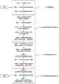
一种工程曲线群自动生成系统,其结构如图1所示,包括:An engineering curve group automatic generation system, its structure is shown in Figure 1, including:
基础曲线生成模块101,用于根据输入点计算生成三个描述体系,基础曲线生成模块101具体包括:体系计算子模块,用于根据曲线局部的曲率特征自动加密控制点,进而建立同一条曲线的标准基础方程体系、绘图结构体系和精密点线结构体系,以满足不同工程应用的需要;自动纠错子模块,用于纠正计算过程中因计算机精度误差所引起点偏离、曲线线型错误等问题;体系计算子模块与自动纠错子模块相连。The basic curve generation module 101 is used to calculate and generate three description systems according to the input points. The basic curve generation module 101 specifically includes: a system calculation sub-module, which is used to automatically encrypt the control points according to the local curvature characteristics of the curve, and then establish the same curve. Standard basic equation system, drawing structure system and precise point-line structure system to meet the needs of different engineering applications; automatic error correction sub-module is used to correct problems such as point deviation and curve line type errors caused by computer precision errors during the calculation process ; The system calculation sub-module is connected with the automatic error correction sub-module.
高级应用模块102,用于根据基础曲线模块101生成的三个描述体系的参数完成复杂曲线或者曲线群的绘图,包括曲线连接子模块和曲线偏移子模块;曲线偏移子模块用于计算基础曲线偏移极限,并在偏移极限内计算生成偏移曲线;曲线连接子模块用于实现曲线或曲线群的平滑连接,综合解决一条基础曲线不等距偏移生成的多条曲线任意两端点之间、两条基础曲线上任意两点之间、两条基础曲线等距或不等距偏移生成的曲线任意两个端点之间的平滑连接问题。上述过程中,偏移曲线和连接曲线也可按需表达为三种描述体系并支持复用。The advanced application module 102 is used to complete the drawing of complex curves or curve groups according to the parameters of the three description systems generated by the basic curve module 101, including the curve connection sub-module and the curve offset sub-module; the curve offset sub-module is used to calculate the basic Curve offset limit, and calculate and generate offset curve within the offset limit; the curve connection sub-module is used to realize the smooth connection of curves or curve groups, and comprehensively solve any two ends of multiple curves generated by a basic curve with unequal distance offset Between, between any two points on two base curves, and between any two endpoints of a curve generated by equidistant or unequal offset of two base curves. In the above process, the offset curve and connection curve can also be expressed as three description systems as needed and support reuse.
数据综合模块103,用于汇集基础曲线生成模块101和高级应用模块102的数据进行组织后存储以及按照需求分别为汇集基础曲线生成模块101和高级应用模块102提供数据;数据综合模块103包括数据组织子模块、数据存储子模块和数据传输子模块;数据组织子模块用于综合各曲线的描述体系、实现体系间的参数映射,支持不同应用需求下曲线描述体系的快速切换;数据存储子模块用于存储系统中的曲线数据以及映射对应关系;数据传输子模块用于接收其他子模块运算结果并根据其他子模块的操作目标及计算需求,调取相关基础曲线数据和必要的描述体系参数并传输。数据组织子模块和数据传输子模块分别与数据存储子模块相连;数据组织子模块分别与基础曲线生成模块101和高级应用模块102相连;数据存储子模块分别与基础曲线生成模块101和高级应用模块102相连;数据传输子模块分别与基础曲线生成模块101和高级应用模块102相连。The data synthesis module 103 is used to collect the data of the basic curve generation module 101 and the advanced application module 102 for organizing and storing and provide data for the collection of the basic curve generation module 101 and the advanced application module 102 respectively according to requirements; the data synthesis module 103 includes data organization Sub-module, data storage sub-module and data transmission sub-module; the data organization sub-module is used to synthesize the description systems of each curve, realize the parameter mapping between systems, and support the rapid switching of curve description systems under different application requirements; the data storage sub-module is used to The curve data in the storage system and the corresponding mapping relationship; the data transmission sub-module is used to receive the calculation results of other sub-modules, and according to the operation objectives and calculation requirements of other sub-modules, retrieve relevant basic curve data and necessary description system parameters and transmit them . The data organization sub-module and the data transmission sub-module are respectively connected with the data storage sub-module; the data organization sub-module is respectively connected with the basic curve generation module 101 and the advanced application module 102; the data storage sub-module is respectively connected with the basic curve generation module 101 and the advanced application module 102; the data transmission sub-module is connected to the basic curve generation module 101 and the advanced application module 102 respectively.
基础曲线生成模块101和高级应用模块102分别与数据综合模块103相连。The basic curve generation module 101 and the advanced application module 102 are respectively connected with the data integration module 103 .
如图2所示,其描述了一个本工程曲线群自动生成系统适用的实例,包括:基础曲线L1、L2,偏移曲线群GO1、GO2和连接线群GC。As shown in Figure 2, it describes an example of the application of the automatic generation system of curve groups in this project, including: base curves L1 , L2 , offset curve groups GO1 , GO2 and connecting line group GC .
其中基础曲线、偏移曲线群和连接线群的定义分别为:The definitions of base curve, offset curve group and connecting line group are respectively:
图中粗虚线表示基础曲线,由基础曲线生成模块根据输入点绘制生成;The thick dotted line in the figure represents the basic curve, which is drawn and generated by the basic curve generation module according to the input points;
图中实线包围的线条为偏移曲线群,由曲线偏移子模块根据基础曲线指定部分绘制生成;The lines surrounded by solid lines in the figure are offset curve groups, which are drawn and generated by the curve offset sub-module according to the specified part of the base curve;
图中实线包围范围外的线条为连接线群,由曲线连接子模块根据基础曲线指定部分绘制生成。The lines outside the range surrounded by the solid line in the figure are connecting line groups, which are drawn and generated by the curve connection sub-module according to the specified part of the basic curve.
本实施例中基础曲线生成模块101内嵌有基础曲线生成程序,其流程如图3所示,包括:In this embodiment, the basic curve generation module 101 is embedded with a basic curve generation program, and its flow process is as shown in Figure 3, including:
步骤1:根据输入坐标数据,进行参数准备;Step 1: Prepare parameters according to the input coordinate data;
步骤1-1:记录输入点坐标,将其存储为双精度浮点数值对列表PLO;Step 1-1: record the coordinates of the input point, and store it as a double-precision floating-point value pair list PLO ;
步骤1-2:记录首末点的切矢量约束Ss和St,如果有约束,则将其记录为双精度浮点数值对;如果无约束,则将Ss和St设置为null值;Step 1-2: Record the tangent vector constraints Ss and St of the first and last points. If there are constraints, record them as double-precision floating-point value pairs; if there are no constraints, set Ss and St to null values ;
步骤1-3:输入用于生成绘图结构体系的曲线拟合误差εD和用于生成精密点线结构的拟合误差εS,有εS<εD。Step 1-3: Input the curve fitting error εD used to generate the drawing structure system and the fitting error εS used to generate the precise point-line structure, and εS <εD .
步骤2:生成标准基础方程体系;Step 2: generate standard basic equation system;
步骤2-1:根据Ss和St的赋值情况预处理PLO得到用于计算的双精度浮点数值对列表
首先判断Ss和St是否为null;First judge whether Ss and St are null;
若Ss和St是否均为null,则令
若Ss和St是否均不为null,为避免固定断点切矢量条件下因曲线自动计算引起的如图4所示的虚线交叉情况,在自动纠错子模块中完成计算过程如图5所示,包括:由起终点Ps和Pt分别沿起点切矢量反方向S's和终点的切矢量方向St,向曲线两侧延伸一个长度为δ的线段,分别得到另外两个端点P's和P't,将其分别插入PLO首点位置和追加PLO末尾位置,综合形成
若Ss和St中有任意一项不为null,则在自动纠错子模块中仅对不为null的端点进行延长和增点操作,自动纠错子模块完成计算后,输出
步骤2-2:以
判断
同时,为了避免样条曲线反弯引起的线型不平滑问题,在自动纠错子模块中完成纠错过程,具体方法为:判断CFL'中各子曲线段方程是否有驻点,若是,则将所有驻点按照出现的位置插入


步骤2-3:在体系计算子模块中整理标准基础方程,具体方法为:Step 2-3: Organize the standard basic equations in the system calculation sub-module, the specific method is:
若Ss不为null,则从

若St不为null,则从

若Ss和St均为null,则不做修改;If both Ss and St are null, no modification will be made;
最后返回标准基础方程体系的控制点列表

步骤2-4:由CFL和PL可综合计算得到PL每个控制点处的曲线切实量斜率,综合形成列表GL={Gn,n=1,2,…,NF},NF为PL的内点个数;Step 2-4: From CFL and PL, the actual slope of the curve at each control point of PL can be calculated comprehensively, and a comprehensive list GL={Gn ,n=1,2,...,NF }, whereNF is PL The number of interior points;
步骤2-5:至此,曲线的基础方程体系参数全部生成,基础方程体系参数包括PL、CFL和GL,将基础方程体系参数存储至数据综合模块103。基础方程体系参数用于其他两个描述体系的参数生成,如有关键点坐标更新可在原方程基础上快速局部更新;另外在工程对其他两个体系精度要求发生变化时,可基于基础方程体系参数快速重新计算。Step 2-5: So far, all the parameters of the basic equation system of the curve are generated. The parameters of the basic equation system include PL, CFL and GL, and the parameters of the basic equation system are stored in the data integration module 103 . The parameters of the basic equation system are used to generate the parameters of the other two description systems. If there is a key point coordinate update, it can be quickly and locally updated on the basis of the original equation; Fast recalculation.
步骤3:根据标准基础方程参数生成绘图结构体系,获得参数DPL、DGL和BFL;Step 3: Generate the drawing structure system according to the standard basic equation parameters, and obtain the parameters DPL, DGL and BFL;
步骤3-1:计算标准基础方程体系中,每两个相邻控制点之间的绘图加密控制点及对应斜率信息,处理过程如图6所示,具体方法为:Step 3-1: Calculate the drawing encrypted control points and corresponding slope information between every two adjacent control points in the standard basic equation system. The processing process is shown in Figure 6, and the specific method is as follows:
P1和P2为曲线中标准基础方程体系中PL中连续的两个控制点,连接点P1和P2的曲线弧为

步骤3-2:遍历PL上所有的连续控制点对,按步骤3-1递归计算并综合得到绘图结构控制点集DPL以及对应的斜率集DGL;Step 3-2: traverse all the continuous control point pairs on the PL, recursively calculate and synthesize the drawing structure control point set DPL and the corresponding slope set DGL according to step 3-1;
步骤3-3:将DPL中每两个相邻点及DGL中对应的斜率作为输入,顺次计算对应的二次贝塞尔子曲线方程,按序综合记录贝塞尔曲线方程序列BFL;Step 3-3: Take every two adjacent points in DPL and the corresponding slope in DGL as input, sequentially calculate the corresponding quadratic Bezier sub-curve equations, and comprehensively record the Bezier curve equation sequence BFL sequentially;
步骤3-4:标记DPL中属于PL的控制点以及其他新增控制点分别由CFL中哪一个子方程曲线细分生成,其中DPL包括点个数为ND;Step 3-4: Mark the control points belonging to the PL in the DPL and other newly added control points which are respectively generated by subdivision of the sub-equation curve in the CFL, wherein the number of points included in the DPL is ND ;
步骤3-5:至此绘图结构体系参数全部生成,绘图结构体系参数包括DPL、DGL和BFL,并将绘图结构体系参数存储至数据综合模块103。绘图结构体系以极低的计算代价在规定精度水平下以二次贝塞尔曲线方程替代样条曲线方程,实现了方程降阶;另外,二次贝塞尔曲线作为计算机图形学基础曲线类型之一,在大多绘图工具中可由点集DPL直接快速绘制,故绘图结构体系可用于曲线或曲线群快速绘图,并为精密点线结构生成、曲线偏移、连接线绘制提供参数计算基础。Step 3-5: So far all the drawing structure system parameters are generated, the drawing structure system parameters include DPL, DGL and BFL, and the drawing structure system parameters are stored in the data integration module 103 . The drawing structure system replaces the spline curve equation with the quadratic Bezier curve equation at a specified level of accuracy at a very low calculation cost, and realizes the reduction of the equation; in addition, the quadratic Bezier curve is one of the basic curve types of computer graphics. First, in most drawing tools, the point set DPL can be directly and quickly drawn, so the drawing structure system can be used for fast drawing of curves or curve groups, and provides a parameter calculation basis for precise point-line structure generation, curve offset, and connecting line drawing.
步骤4:根据参数DPL和BFL生成精密点线结构体系。Step 4: Generate the precise point-line structure system according to the parameters DPL and BFL.
步骤4-1:以步骤3-1和步骤3-2同理的方法,将BFL中各贝塞尔子曲线段再次细分,生成精密点线结构控制点列表SPL,本步骤与步骤3-1和步骤3-2的差别在于:Step 4-1: In the same way as Step 3-1 and Step 3-2, subdivide each Bezier sub-curve segment in the BFL again to generate a precise point-line structure control point list SPL. This step is the same as Step 3- The difference between 1 and step 3-2 is:
(1)误差水平取εS,细分要求更高,生成的点线结构以更高精度拟合BFL;(1) The error level is εS , the subdivision requirements are higher, and the generated point-line structure fits the BFL with higher precision;
(2)细分对象为二次贝塞尔曲线,考虑到此类曲线的特性,每段弧的细分点可直接取该弧中点,省略求解与弧相切且与弦平行的直线方程一步,效率可进一步提升;(2) The subdivision object is a quadratic Bezier curve. Considering the characteristics of this type of curve, the subdivision point of each arc can directly take the midpoint of the arc, omitting to solve the equation of a line tangent to the arc and parallel to the chord One step, the efficiency can be further improved;
步骤4-2:判断SPL中属于DPL的控制点以及其他新增控制点分别由BFL中哪一个子方程曲线细分生成,其中SPL包括点个数为Ns;Step 4-2: Determine which sub-equation curve subdivision in the BFL generates the control points belonging to the DPL in the SPL and other newly added control points, wherein the number of points included in the SPL is Ns ;
步骤4-3:至此精密点线结构体系参数全部生成,包括SPL以及步骤4-1中的对应信息,并将密点线结构体系参数存储至数据综合模块103。精密点线结构有相对绘图结构体系更高的精度和更低的方程阶数,适于大量的曲线计算,可用于高精度要求下的曲线复用,如路径仿真、曲线轨迹跟踪等。Step 4-3: Up to now, all the parameters of the precise point-line structure system are generated, including the SPL and the corresponding information in step 4-1, and the parameters of the dense point-line structure system are stored in the data synthesis module 103 . The precision point-line structure has higher precision and lower equation order than the drawing structure system, which is suitable for a large number of curve calculations and can be used for curve reuse under high precision requirements, such as path simulation, curve track tracking, etc.
本实施例中曲线偏移子模块中内嵌有曲线偏移程序,其流程如图7所示,包括:In this embodiment, a curve offset program is embedded in the curve offset submodule, and its flow process is shown in Figure 7, including:
步骤5-1:获取ODir和偏移距离ODis,其中ODis以二值化表示,取值范围为{-1,1};Step 5-1: Obtain ODir and offset distance ODis, where ODis is represented by binarization, and the value range is {-1,1};
步骤5-2:由数据综合模块提取基础曲线绘图结构体系中的绘图控制点集DPL、对应的斜率集DGL及DPL点数ND,如果ND=2,则执行步骤5-8,否则依次连接相邻的绘图点对,构成连续的点线结构DS;Step 5-2: Extract the drawing control point set DPL, the corresponding slope set DGL and the number of DPL pointsND in the basic curve drawing structure system by the data synthesis module, ifND = 2, then perform steps 5-8, otherwise connect sequentially Adjacent drawing point pairs form a continuous point-line structure DS;
步骤5-3:构建偏移参考线集合,如图8所示,具体方法为:粗实线为DS,过DS首点求解DS第一条线段的垂线VLs;过DS末点求解DS最后一条线段的垂线VLt,过中间各点,在其与前后点连线形成小于平角的一侧求解角分线方程ALm(m=1,2,......ND-2),构成偏移参考线集合OLL={VLs,ALm,VLt};Step 5-3: Build a set of offset reference lines, as shown in Figure 8. The specific method is: the thick solid line is DS, and the vertical line VLs of the first line segment of DS is obtained through the first point of DS; the vertical line VL s of the first line segment of DS is obtained through the end point of DS; The vertical line VLt of the last line segment passes through the middle points, and solves the angle-division line equation ALm (m=1,2,...ND- 2) Constitute the set of offset reference lines OLL={VLs , ALm , VLt };
步骤5-4:判断是否需要求解偏移极限,如图8所示,具体方法为:检索数据综合模块103,检查是否已经记录基础曲线的偏移极限,如果有,则执行步骤5-6,否则,执行步骤5-5;Step 5-4: Judging whether the offset limit needs to be solved, as shown in Figure 8, the specific method is: retrieve the data synthesis module 103, check whether the offset limit of the basic curve has been recorded, if so, then perform step 5-6, Otherwise, perform steps 5-5;
步骤5-5:求解DS子段的偏移极限,求解VLs与的AL1交点PXs及其与第一条线段的距离ds,VLt与
步骤5-6:综合求解DS的偏移极限,具体方法为:分别汇总向两侧偏移的限制距离列表,并取各自最小值,分别得到dl1和dl2,如果某一侧无任何限制值,则本侧可无限偏移,偏移极限为Infinity,同时将求得的偏移极限写入数据综合模块103以备后续检索;Step 5-6: Comprehensively solve the offset limit of DS, the specific method is: sum up the list of limit distances offset to both sides respectively, and take the respective minimum values to obtain dl1 and dl2 respectively, if there is no limit on one side value, then this side can be infinitely offset, and the offset limit is Infinity, and the offset limit obtained is written into the data integration module 103 for subsequent retrieval;
步骤5-7:判断ODis是否超出ODir一侧的偏移极限,具体方法为:如果未超出,则执行步骤5-8,否则提示超出限制;Step 5-7: Determine whether the ODis exceeds the offset limit on the ODir side, the specific method is: if not, execute steps 5-8, otherwise it prompts that the limit is exceeded;
步骤5-8:根据偏移目的决定偏移基础点集:如果偏移目的是绘制偏移曲线,则执行步骤5-9,如果偏移目的为应用曲线线型计算,则执行步骤5-10;Step 5-8: Determine the base point set for the migration according to the purpose of the migration: if the purpose of the migration is to draw the migration curve, perform steps 5-9, and if the purpose of the migration is to apply curve line type calculation, perform steps 5-10 ;
步骤5-9:利用DPL和DGL求解偏移曲线,具体方法为:如果DPL仅包括两点,说明为直线,根据ODir和ODis求解该直线的平行线方程;否则,由DPL点集沿OLL或OLL的反向延长线方向向ODir方向移动ODis距离,求解移动后点坐标集合OPL,匹配基础曲线的绘图体系斜率集DGL,得到偏移曲线的绘图体系参数集,将OPL、DGL、ODir和ODis写入数据综合模块103,可用于绘制偏移曲线Step 5-9: Use DPL and DGL to solve the offset curve. The specific method is: if the DPL only includes two points, which is described as a straight line, solve the parallel line equation of the straight line according to ODir and ODis; otherwise, use the DPL point set along the OLL or Move the ODis distance from the direction of the reverse extension line of the OLL to the direction of ODir, solve the point coordinate set OPL after the movement, match the drawing system slope set DGL of the basic curve, and obtain the drawing system parameter set of the offset curve, and combine OPL, DGL, ODir and ODis Write into the data synthesis module 103, which can be used to draw the offset curve
步骤5-10:利用SPL拟合偏移曲线,具体方法为:由数据综合模块103提取基础曲线精密点线结构体系中的控制点集SPL,如果SPL仅包括两点,说明为直线,根据ODir和ODis求解该直线的平行线方程;否则,基于SPL构成连续的点线结构SS,使用步骤5-2所述的方法求解SS对应的偏移参考线集合OLL',同时参考步骤5-8的方法求解偏移点坐标集合OPL',即偏移曲线的精密点线结构体系参数集,将OLL'、OPL'、ODir和ODis写入数据综合模块103,可用于偏移曲线的高精度工程应用。Step 5-10: use SPL to fit the offset curve, the specific method is: extract the control point set SPL in the precise point-line structure system of the basic curve by the data synthesis module 103, if the SPL only includes two points, it is described as a straight line, according to ODir and ODis to solve the parallel line equation of the straight line; otherwise, form a continuous point-line structure SS based on SPL, use the method described in step 5-2 to solve the offset reference line set OLL' corresponding to SS, and refer to step 5-8 The method solves the offset point coordinate set OPL', that is, the precise point-line structure system parameter set of the offset curve, and writes OLL', OPL', ODir, and ODis into the data synthesis module 103, which can be used for high-precision engineering applications of the offset curve .
本实施例中曲线连接子模块中内嵌有曲线连接程序,其流程如图9所示,包括:In this embodiment, a curve connection program is embedded in the curve connection submodule, and its flow process is as shown in Figure 9, including:
步骤6-1:获取需要进行连接的曲线C1和C2及其要连接的目标位置数据;Step 6-1: Obtain the curves C1 and C2 that need to be connected and the data of the target position to be connected;
步骤6-2:如果目标连接位置精确位于曲线上,记为O1和O2,由数据综合模块103提取该曲线绘图体系方程BFL,由该点所在方程可求连接端点对应切实量斜率S1和S2,然后执行步骤6-4;否则执行步骤6-3;Step 6-2: If the target connection position is accurately located on the curve, denoted as O1 and O2 , the data integration module 103 extracts the equation BFL of the curve drawing system, and the actual slope S1 corresponding to the connection end point can be obtained from the equation where the point is located and S2 , then go to step 6-4; otherwise go to step 6-3;
步骤6-3:如果目标位置通过点击屏幕选取,一般不精确位于C1和C2曲线上而在与其接近的位置O'1、O'2,应自动搜索定位到曲线上,如图10所示,图中灰色实线为实际曲线,虚线为精密点线结构,具体方法为:由数据综合模块103提取该曲线精密点线结构体系中的控制点集SPL,分别连接O′与SPL上各点,找到距离最小的两个点PO1和PO2,由O′向线段PO1PO2连线做垂线,其与PO1PO2对应的贝塞尔方程BF的交点即为曲线上的实际目标位置O,根据O的坐标及BF,可求O点切矢量斜率;按照上述方法,求得真实曲线连接端点O1和O2及其对应切矢量斜率S1和S2;Step 6-3: If the target position is selected by clicking on the screen, generally it is not precisely located on the C1 and C2 curves but at positions O'1 and O'2 close to them, it should be automatically searched and positioned on the curves, as shown in Figure 10 As shown, the gray solid line in the figure is the actual curve, and the dotted line is the precise point-line structure. The specific method is: extract the control point set SPL in the precise point-line structure system of the curve by the data synthesis module 103, and connect O' and each on the SPL respectively point, find the two points PO1 and PO2 with the smallest distance, draw a vertical line from O′ to the line segment PO1 PO2 , and the intersection point of the Bessel equation BF corresponding to PO1 PO2 is the point on the curve The actual target position O, according to the coordinates of O and BF, the slope of the tangent vector at point O can be obtained; according to the above method, the real curve connecting endpoints O1 and O2 and their corresponding tangent vector slopes S1 and S2 are obtained;
步骤6-4:确定连接目的,连接目的包括:Step 6-4: Determine the connection purpose, which includes:
最基础的应用为连接两条基础曲线上的任意两点;实际工程中应用连接线的场景一般是对一组偏移后的曲线进行操作,同时要求连接线满足限定要求,包括:如图11所示,虚线为基础曲线,将其不同子段分别偏移不同距离得到的两个偏移曲线群A和B,要求连接线相对基础曲线的偏移不超过要连接的两个端点偏移距离,并且连接一组偏移曲线时连接线之间的空间不存在挤压现象;对于由两条不同的基础曲线等距或不等距偏移生成的曲线上,任意两个端点之间的平滑连接问题;The most basic application is to connect any two points on two basic curves; the scene of applying connection lines in actual engineering is generally to operate on a set of offset curves, and at the same time require the connection lines to meet the limited requirements, including: Figure 11 As shown, the dotted line is the base curve, and the two offset curve groups A and B are obtained by offsetting different sub-sections by different distances. It is required that the offset of the connecting line relative to the base curve does not exceed the offset distance of the two endpoints to be connected , and there is no squeeze in the space between the connecting lines when connecting a set of offset curves; for a curve generated by offsetting two different base curves with or without equidistant offsets, the smoothness between any two endpoints connection problems;
连接目的以及相应的处理方法具体为:The purpose of the connection and the corresponding processing method are as follows:
基础应用连接,执行步骤6-5;Basic application connection, perform steps 6-5;
实际工程应用连接,执行步骤6-6;For actual engineering application connection, perform steps 6-6;
端点间平滑连接,执行步骤6-11;For smooth connection between endpoints, perform steps 6-11;
步骤6-5:参照步骤2-1、步骤2-2和步骤2-3的方法,根据O1、O2及S1、S2可以两端约束的样条曲线方程作为求解连接线的标准基础方程,连接线在首末端与原有曲线相切,实现平滑连接,且可根据应用需求决定是否生成绘图结构体系和精密点线结构体系,完成基础应用连接,至此两条基础曲线上任意两点之间连接问题可解;Step 6-5: Referring to the methods of Step 2-1, Step 2-2 and Step 2-3, according to O1 , O2 and S1 , S2 , the spline curve equation constrained at both ends can be used as the standard for solving the connection line The basic equation, the connection line is tangent to the original curve at the beginning and end, to achieve a smooth connection, and it can be determined whether to generate a drawing structure system and a precise point-line structure system according to application requirements, and complete the basic application connection. The connection problem between points can be solved;
步骤6-6:由数据综合模块103提取基础曲线的绘图体系结构参数BFL、精密点线结构体系参数SPL、各条偏移曲线的参数包括ODis和ODir;Step 6-6: The drawing system parameter BFL of the basic curve, the precise point-line structure system parameter SPL, and the parameters of each offset curve include ODis and ODir are extracted by the data synthesis module 103;
步骤6-7:计算参数预处理,具体处理方法为:Step 6-7: Calculation parameter preprocessing, the specific processing method is:
如图12所示,按照步骤6-2和步骤6-3的方法,计算得到要连接两条偏移线的端点坐标OO1、OO2及其对应切矢量斜率OS1、OS2之后,同时记录两者在BFL上映射的点坐标为AP1、AP2;提取AP1、AP2之间包括的BFL中的点集MPc,并和AP1、AP2构成基础曲线参考点线结构PC={AP1,MPc,AP2};计算PC点集与首点AP1的累计距离集合PCd={dj,j=1,2,......,Nm},其中Nm为PC点个数,并计算累计距离占总距离比集合PCp={dj/dNm};记录各自偏移距离为


步骤6-8:根据目标线型连接要求,确定线性偏移距离表,具体方法为:指定若干个关键累计距离占总几率比例位置,约定与之对应的偏移距离占AD的比例,通过引入不同的线性偏移距离表,可构建不同的连接线型;Step 6-8: Determine the linear offset distance table according to the connection requirements of the target line type. The specific method is: specify a number of key positions where the cumulative distance accounts for the total probability ratio, and agree on the proportion of the corresponding offset distance to AD. By introducing Different linear offset distance tables can build different connection line types;
步骤6-9:计算连接线控制点集,如图12所示,具体方法为:根据PCp、AD和线性偏移距离表,使用线型插值法计算PC各点应当偏移的距离,并按照步骤5-10的方法进行偏移,得到图中粗线圆圈表示的连接线控制点集CPC;Step 6-9: Calculate the control point set of the connection line, as shown in Figure 12, the specific method is: according to PCp, AD and the linear offset distance table, use the linear interpolation method to calculate the offset distance of each point of PC, and follow The method of steps 5-10 is offset to obtain the connection line control point set CPC represented by the thick line circle in the figure;
步骤6-10:由OS1、OS2和CPC利用步骤2-1的方法,求解连接线的标准基础方程,连接线在首末端与原有曲线相切,实现平滑连接,根据应用需求决定是否生成绘图结构体系和精密点线结构体系,至此由一条基础曲线不等距偏移生成的曲线任意两个端点之间问题可解;Step 6-10: OS1 , OS2 and CPC use the method of step 2-1 to solve the standard basic equation of the connection line. The connection line is tangent to the original curve at the beginning and end to achieve a smooth connection. It is decided according to the application requirements whether Generate a drawing structure system and a precise point-line structure system, so far the problem between any two endpoints of a curve generated by an unequal offset of a basic curve can be solved;
步骤6-11:可利用步骤2-1的方法,求解两条基础曲线的连接曲线,并由步骤3和步骤4计算连接曲线的精密点线结构作为步骤6-6中的基础曲线参考点线结构,按照步骤6-8和步骤6-9的方法可实现两条不同的基础曲线等距或不等距偏移生成的曲线上端点间的平滑连接。Step 6-11: The method of step 2-1 can be used to solve the connection curve of the two basic curves, and the precise point line structure of the connection curve is calculated by steps 3 and 4 as the reference point line of the basic curve in step 6-6 Structure, according to the method of steps 6-8 and 6-9, the smooth connection between the endpoints on the curves generated by two different basic curves with equidistant or unequal distance offset can be realized.
本实施例中的工程曲线群自动生成系统具有以下创新点:The engineering curve group automatic generation system in this embodiment has the following innovations:
(1)以三种有递进关系的体系共同描述曲线,计算过程中按需记录各体系参数及体系间的联系,快速根据应用要求提取相关数据,满足不同精度层次、面向不同需求的曲线操作要求。(1) Use three systems with progressive relationships to jointly describe the curve, record the parameters of each system and the relationship between the systems as needed during the calculation process, quickly extract relevant data according to application requirements, and meet different precision levels and curve operations for different needs Require.
(2)提供了基于基础曲线的曲线偏移、曲线对连接、由基础曲线偏移生成的高级曲线的连接算法,在工程约束下自动化生成偏移曲线和连接曲线,可支撑工程应用中曲线群的生成;(2) Provides curve offset based on basic curves, curve pair connection, and advanced curve connection algorithms generated by basic curve offsets, automatically generates offset curves and connection curves under engineering constraints, and can support curve groups in engineering applications generation;
(3)考虑计算机自动绘图实现过程中的精度限制,总结因精度问题导致的算法无法正确实施、导致错误或崩溃等问题,提出补偿算法并实现自动纠错和校正。(3) Considering the precision limitation in the process of computer automatic drawing realization, sum up the problems that the algorithm cannot be implemented correctly, lead to errors or crashes caused by the precision problem, propose a compensation algorithm and realize automatic error correction and correction.
以上所述,仅为本发明的具体实施方式,但本发明的保护范围并不局限于此,任何熟悉本技术领域的技术人员在本发明揭露的技术范围内,可轻易想到各种等效的修改或替换,这些修改或替换都应涵盖在本发明的保护范围之内。因此,本发明的保护范围应以权利要求的保护范围为准。The above is only a specific embodiment of the present invention, but the protection scope of the present invention is not limited thereto. Any person familiar with the technical field can easily think of various equivalents within the technical scope disclosed in the present invention. Modifications or replacements shall all fall within the protection scope of the present invention. Therefore, the protection scope of the present invention should be based on the protection scope of the claims.
Claims (6)


Priority Applications (1)
| Application Number | Priority Date | Filing Date | Title |
|---|---|---|---|
| CN202011131592.2ACN112330770B (en) | 2020-10-21 | 2020-10-21 | An Automatic Generation System of Engineering Curve Groups |
Applications Claiming Priority (1)
| Application Number | Priority Date | Filing Date | Title |
|---|---|---|---|
| CN202011131592.2ACN112330770B (en) | 2020-10-21 | 2020-10-21 | An Automatic Generation System of Engineering Curve Groups |
Publications (2)
| Publication Number | Publication Date |
|---|---|
| CN112330770A CN112330770A (en) | 2021-02-05 |
| CN112330770Btrue CN112330770B (en) | 2023-06-02 |
Family
ID=74311942
Family Applications (1)
| Application Number | Title | Priority Date | Filing Date |
|---|---|---|---|
| CN202011131592.2AActiveCN112330770B (en) | 2020-10-21 | 2020-10-21 | An Automatic Generation System of Engineering Curve Groups |
Country Status (1)
| Country | Link |
|---|---|
| CN (1) | CN112330770B (en) |
Families Citing this family (2)
| Publication number | Priority date | Publication date | Assignee | Title |
|---|---|---|---|---|
| CN114741914B (en)* | 2022-03-10 | 2025-06-20 | 湖南省交通规划勘察设计院有限公司 | A forward design method for bridge tower based on BIM technology |
| CN116051674A (en)* | 2022-12-29 | 2023-05-02 | 杭州海康威视系统技术有限公司 | Electronic whiteboard line drawing method, electronic whiteboard and storage medium |
Citations (6)
| Publication number | Priority date | Publication date | Assignee | Title |
|---|---|---|---|---|
| US6404434B1 (en)* | 1998-09-04 | 2002-06-11 | Sony Corporation | Curve generating apparatus and method, storage medium storing curve generating program, and method of setting associate points |
| JP2004054748A (en)* | 2002-07-23 | 2004-02-19 | Ricoh Co Ltd | Three-dimensional shape processing device, three-dimensional shape processing method, three-dimensional shape processing program, and recording medium |
| CN101796546A (en)* | 2007-10-30 | 2010-08-04 | 国立大学法人横滨国立大学 | Interpolation processing method and interpolation processing device |
| CN102637216A (en)* | 2011-12-14 | 2012-08-15 | 南京航空航天大学 | Method for generating numerical-control side milling machining tool path for complicated curved surfaces |
| CN110335328A (en)* | 2019-06-25 | 2019-10-15 | 杭州汇萃智能科技有限公司 | A kind of curve plotting method based on B-spline, system and storage medium |
| CN110414706A (en)* | 2018-04-28 | 2019-11-05 | 西安合众思壮导航技术有限公司 | Method, device and system for generating curved paths |
Family Cites Families (3)
| Publication number | Priority date | Publication date | Assignee | Title |
|---|---|---|---|---|
| US7136505B2 (en)* | 2002-04-10 | 2006-11-14 | National Instruments Corporation | Generating a curve matching mapping operator by analyzing objects of interest and background information |
| US8520003B2 (en)* | 2006-05-22 | 2013-08-27 | Raphael L Levien | Method and apparatus for interactive curve generation |
| KR102219294B1 (en)* | 2014-02-13 | 2021-02-23 | 삼성전자 주식회사 | Method and apparatus for rendering curve |
- 2020
- 2020-10-21CNCN202011131592.2Apatent/CN112330770B/enactiveActive
Patent Citations (6)
| Publication number | Priority date | Publication date | Assignee | Title |
|---|---|---|---|---|
| US6404434B1 (en)* | 1998-09-04 | 2002-06-11 | Sony Corporation | Curve generating apparatus and method, storage medium storing curve generating program, and method of setting associate points |
| JP2004054748A (en)* | 2002-07-23 | 2004-02-19 | Ricoh Co Ltd | Three-dimensional shape processing device, three-dimensional shape processing method, three-dimensional shape processing program, and recording medium |
| CN101796546A (en)* | 2007-10-30 | 2010-08-04 | 国立大学法人横滨国立大学 | Interpolation processing method and interpolation processing device |
| CN102637216A (en)* | 2011-12-14 | 2012-08-15 | 南京航空航天大学 | Method for generating numerical-control side milling machining tool path for complicated curved surfaces |
| CN110414706A (en)* | 2018-04-28 | 2019-11-05 | 西安合众思壮导航技术有限公司 | Method, device and system for generating curved paths |
| CN110335328A (en)* | 2019-06-25 | 2019-10-15 | 杭州汇萃智能科技有限公司 | A kind of curve plotting method based on B-spline, system and storage medium |
Also Published As
| Publication number | Publication date |
|---|---|
| CN112330770A (en) | 2021-02-05 |
Similar Documents
| Publication | Publication Date | Title |
|---|---|---|
| CN112330770B (en) | An Automatic Generation System of Engineering Curve Groups | |
| CN109949389A (en) | An intersection drawing method, device, server and storage medium | |
| CN109993064B (en) | Method for extracting connection path between road network nodes in picture | |
| CN113312369A (en) | Multi-scale map database cascading updating method based on unique identification code | |
| CN113449735A (en) | Semantic segmentation method and device for superpixel segmentation | |
| CN113721969A (en) | Multi-scale space vector data cascade updating method | |
| CN105513083A (en) | PTAM camera tracking method and device | |
| CN111310278A (en) | Ship automatic modeling method based on simulation | |
| CN108537263B (en) | Grid map fusion method based on maximum public subgraph | |
| CN109213941B (en) | A Method for Mining Frequent Patterns of Indoor Trajectories Based on Fuzzy Grid Sequence | |
| CN114283250A (en) | High-precision automatic splicing and optimizing method and system for three-dimensional point cloud map | |
| CN110704559A (en) | A Multi-scale Vector Surface Data Matching Method | |
| CN103902343A (en) | Tile map downloading and splicing method based on Delaunay triangulation network accuracy control | |
| CN113239905A (en) | Lane line simplification method and device, electronic equipment and storage medium | |
| CN112766385A (en) | Many-source vector line data geometric matching and attribute fusion method | |
| Zhang et al. | Knowledge-based image analysis for 3D edge extraction and road reconstruction | |
| CN116933357A (en) | Geometric linear parameterized road modeling method based on point cloud data | |
| CN115206434A (en) | A Multiple Sequence Alignment Method Based on De Bruijn Diagram | |
| JP4946376B2 (en) | Woven line projection extraction program, weaving line projection extraction apparatus, and ruled line projection extraction method | |
| CN113947678B (en) | An image alignment method suitable for text images | |
| CN113496551B (en) | Terrain section line drawing method based on geological outcrop three-dimensional model | |
| CN114490903A (en) | A road matching method, device, electronic device and storage medium | |
| CN112509025B (en) | Method for calculating rock space structure distance map based on three-dimensional Euclidean distance | |
| US7098912B1 (en) | Method of modifying a volume mesh using sheet insertion | |
| CN109189871A (en) | A kind of method and apparatus of Indoor environment path planning |
Legal Events
| Date | Code | Title | Description |
|---|---|---|---|
| PB01 | Publication | ||
| PB01 | Publication | ||
| SE01 | Entry into force of request for substantive examination | ||
| SE01 | Entry into force of request for substantive examination | ||
| GR01 | Patent grant | ||
| GR01 | Patent grant |